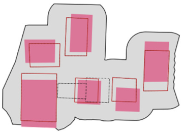
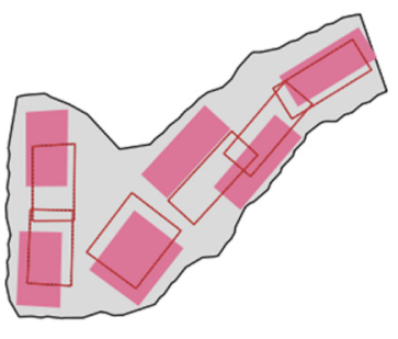
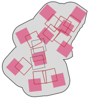
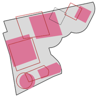
Article

A Zonal Displacement Approach via Grid Point Weighting in Building Generalization

1
Division of Cartography, Department of Geomatic Engineering, Yildiz Technical University, 34220 Istanbul, Turkey
2
Division of Cartography, Department of Geomatic Engineering, Nigde Omer Halisdemir University, 51240 Nigde, Turkey
*
Author to whom correspondence should be addressed.
ISPRS Int. J. Geo-Inf. 2021, 10(2), 105; https://doi.org/10.3390/ijgi10020105
Submission received: 31 December 2020 / Revised: 31 January 2021 / Accepted: 17 February 2021 / Published: 23 February 2021

Abstract

:
When generalizing a group of objects, displacement is an essential operation to resolve the conflicts arising between them due to enlargement of their symbol sizes and reduction of available map space. Although there are many displacement methods, most of them are rather complicated. Therefore, more practical methods are still needed. In this article, a new building displacement approach is proposed. For this purpose, buildings are grouped and zones are created for them in the blocks via Voronoi tessellation and buffering. Linear patterns are then detected through buffer analyses and the respective zones are narrowed to be able to preserve these patterns. After all the buildings are displaced inside their zones, grid points are generated and then weighted through kernel density estimation and buffer analyses to find suitable locations. Accordingly, the buildings are displaced toward the computed locations iteratively. The proposed approach directly enforces minimum distance and positional accuracy constraints while several indirect mechanisms are used for preserving spatial patterns and relationships. For the quality evaluation of the displacement, the angle, length and shape comparison measures are introduced, computed based on the (Delaunay) triangles or the azimuth comparison measure of the connection lines, generated for the buildings. The quality evaluation criteria are yielded according to the visual assessment of the displacement quality and the quantitative analysis of the measures. The findings demonstrate that the proposed approach is quite effective and practical for zonal building displacement.

1. Introduction

When producing maps on a smaller scale and/or a different theme, cartographic generalization is involved to obtain accurate and legible representation of geographic information. The generalization is first applied to individual objects and then to a group of objects. Groups of objects form various spatial contexts. In cartographic generalization, the contextual information should be maintained as far as the target scale allows to convey geographic information to users in a sufficiently accurate manner. Besides, the symbology of the objects has to be adjusted to target scale in terms of discernibility. Consequently, graphic limits become violated in many cases. In order to resolve the graphic conflicts, displacement operation is applied among others. The displacement has not only to ensure minimum acceptable distance among objects but also preserve spatial characteristics and relationships as far as possible. Therefore, it is one of the most complicated operations of contextual cartographic generalization [1,2,3] and is usually needed in the last stage of the generalization. Building generalization is applied up to 1:100K scale. After this scale, instead of individual buildings, built-up areas are shown in general. Since hydrographic and transportation networks surround buildings, they form natural and artificial boundaries for building objects, respectively. Therefore, buildings are often generalized after those kinds of objects. Enlargement of the objects (buildings, roads, etc.) and therefore the occurrence of overlap or the decrease of spacing between them creates conflicts. In addition, previous generalization operations may contribute to the conflict occurrence. In this case, building displacement is applied for the conflict resolution.
The following spatial constraints are regarded during the building displacement [1,4,5]:
  • Minimum distance: minimum spacing between two buildings as well as between a building and a surrounding object such as road, railway and river has to be satisfied to ensure their discernibility at target scale. Minimum distance threshold (MDT) is 0.2 mm (10 m for 1:50k) according to the graphic limits used in cartography.
  • Positional accuracy: Displacement changes the positions of map objects. It should be restricted to preserve positional accuracy of objects within the scale limits. Positional accuracy threshold (PAT) is applied as 0.5 mm (25 m for 1:50k) for buildings.
  • Spatial patterns and relationships: in maps, spatial patterns and relationships of objects should be preserved as much as possible to be able to communicate significant geographic information effectively. In the context of buildings, it is necessary to consider topological, proximal and directional relationships between the buildings as well as between buildings and surrounding objects. For example, according to the Gestalt principles such as continuity and common orientation, specific arrangements of buildings are important in view of visual perception or from a topological aspect, buildings must be located at the same side of the road after generalization.
The first two constraints are principally considered to be stronger than the last because the extraction and the evaluation of spatial patterns and relationships are complex tasks. Therefore, the first two are enforced to access a solution while the last constraint is not enforced directly but proper mechanisms are necessary to maintain them.
There are various methods proposed for building displacement, but they are usually not practical enough to implement in a GIS environment. In addition, the spatial context cannot be precisely described by mechanical or mathematical analysis methods because of the irregular arrangement of the map objects [6]. Very few studies [1,4] mention or consider the effect of individual generalization of both buildings and roads on building displacement. Therefore, the general objective of this study is to develop a practical and sufficiently effective building displacement approach applied in the zones created in the blocks. In this scope, the specific objectives are (1) to detect the zones that include buildings forming linear patterns and to develop a method to preserve those patterns as far as possible, (2) to find convenient locations within the zones dynamically to displace buildings in an iterative way and (3) to propose relevant measures and criteria to evaluate the quality of displacement.
In this context, buildings with graphic conflicts are obtained in groups and the zones are created for the building groups in the blocks in a way that the map space is shared equitably as well as the displacement feasibility of each zone is identified. An experimental study is carried out with a Python extension developed in QGIS to prove the validity of the proposed approach dealing with the displacement of the buildings in topographic map generalization from 1:25k to 1:50k. Meanwhile, the objects individually generalized according to 1:50k in advance were used in the displacement process. In this context, simplification, edge squaring and enlargement were applied for the large (>625 sq m) buildings and collapse and symbolization were applied for small buildings [7].

2. Related Works

Displacement approaches can be categorized into two groups: incremental and holistic approaches. To resolve the conflicts, displacement is applied in sequential steps in the former while the displacement vector is usually computed once in the latter. There are several incremental approaches. In this scope, Ruas [8] presents a sequential displacement approach that allows performing detection and resolution of the conflicts and the evaluation of the displacement results. Lonergan and Jones [9] present an iterative building displacement method through maximizing nearest neighbor distances by regarding legibility constraints. In addition, they compare this method over a simulated annealing-based displacement method and demonstrate some advantages of the former against the latter. Ai and Oosterom [10] use a field-based building displacement. They create displacement fields through the skeleton of Delaunay triangulation and compute the force propagation direction and magnitude in those fields to resolve the conflicts. Lu et al. [11] use the electric field force model for conflict detection and displacement of buildings. In this respect, points are generated along the boundaries of the objects that represent particles with electric power. The conflicts between the objects and the displacement magnitude are determined through electric repulsion between the particles. Basaraner [1] proposes an incremental generalization method for building displacement. He first obtains the proximity clusters to identify the objects in conflict and then creates generalization zones for the clusters through Voronoi tessellation and buffering. After that, displacement candidate and vector are iteratively found by means of Voronoi tessellation, spatial analysis and/or multi-criteria decision making. Sun et al. [12] present an improved immune genetic algorithm (IGA) that satisfies the building alignment constraint and the tangent relation constraint. They compare IGA with genetic algorithm (GA) by applying them in the partitions created by a road network. The superiority of IGA over GA has been shown for resolving graphic conflicts and preserving spatial relationships. Wei et al. [13] present a collaborative displacement method in urban building generalization. They first apply a vector field-based displacement and then evaluate the conflicts between buildings, and between roads and buildings to determine if an additional displacement is needed. Other generalization operations (aggregation, elimination, and constrained reshaping) are then performed to find an acceptable solution from cartographic aspect.
On the other hand, holistic approaches are quite popular among researchers. In this scope, Mackaness [14] proposes a cyclic and iterative displacement algorithm. He identifies spatial conflicts by means of clustering and resolves spatial conflicts via radial displacement while preserving significant spatial relationships. Bader et al. [4] propose an optimization approach for building displacement. They employ a truss structure to hold and preserve significant spatial relationships of buildings. Liu et al. [5] propose a building displacement approach based on a constrained Delaunay triangulation (CDT) skeleton and improved elastic beam algorithm. After partitioning the dataset according to roads, they perform a cyclic and iterative process for detecting conflicts and resolving them via displacement while the skeleton of the gap spaces is obtained with CDT to detect conflicts and construct the proximity graph. The graph is later adjusted using local grouping information and deformed with the improved elastic beam algorithm by means of the forces derived from the detected conflicts. The displacement method attempts to satisfy the cartographic constraints in this way. Ai et al. [15] generate a vector field model to deal with the multiple conflicts in building displacement. A scalar field is created through a Delaunay triangulation skeleton to partition the buildings being processed. A vector field is then formed for conflict detection. The direction and magnitude of the displacement force are computed based on an iso-line model of vector field. Sun et al. [16] apply the snake algorithm for the displacement of buildings. They first partition the map space according to transportation and river networks. Then, the truss structure representing spatial proximity relationships between buildings, and between roads and buildings is generated by means of the weighted proximity graph derived from CDT. Besides, forces between respective objects are calculated with a buffer method and is used in the snake algorithm. In this way, they obtain the results that satisfy cartographic and spatial relationship constraints. Huang et al. [6] use an improved particle swarm optimization (PSO) algorithm for building displacement. In this context, an initial movement vector is calculated with cartographic displacement rules, and the buildings’ original positions are used as the initial particles’ positions. In addition, they compare PSO with an immune genetic algorithm (IGA) and show superiority of the former over the latter. Maruyama et al. [17] tackle with the building displacement as a constrained optimization problem by means of linear programming. They identify spatial relationships among map objects as constraints and optimize the cost function that penalizes excessive displacement of buildings according to the map scale.

3. Methodology and Experimental Setting

3.1. Spatial Partitioning and Building Grouping

It is essential to preserve topological relationships in building displacement. For this purpose, blocks are created by means of surrounding roads (and other linear objects) so that the buildings located at the different sides of the roads cannot interact. In other words, the buildings located in the same block are processed together in displacement. In this study, the road network from 1:50k topographic map was used when creating the blocks.
In view of displacement, it is important to reveal the building groups with MDT. In this context, buffering is applied to buildings in the same blocks regarding the minimum distance criterion imposed by cartographic constraints. In this way, the buildings that are in conflict and would be displaced together are obtained as groups (Figure 1) [18]. This approach is also supported by the findings of Deng et al. [19]. They demonstrate that in terms of the grouping, the buffer analysis approach performs significantly better than remaining eight approaches including SOM, graph clustering and MST among others when the proximity is considered.

3.2. Map Space Allocation for the Building Groups in the Blocks

There are various patterns of buildings. This means a number of different spatial contexts that need to be dealt with cartographic generalization. Therefore, it is not so easy to make proper displacement decisions in the blocks even though the blocks limit the number of buildings to be processed together. In this respect, it is reasonable to form smaller generalization units to make the generalization problem more localized. To this end, generalization zones are created in the blocks through Voronoi tessellation (VT) and buffering, as proposed in [1] (Figure 1a). VT ensures that the map space in blocks is shared equitably between building groups. On the other hand, buffering delimits the movement of buildings in terms of positional accuracy. The generalization zones partly help preserve the spatial relationships between buildings by allowing controlled reduction and/or re-arrangement of associated buildings. More specifically, VT is created via the points densified along the edges of buildings and the resulting Voronoi polygons are then combined according to their intersections with the buildings in the same group. The reason of the densification is to prevent very irregular Voronoi region boundaries between the building groups [18]. In addition, the dissolved PAT-size buffers of those buildings are generated. Following this, the intersection of both geometries is obtained and then clipped according to the MDT allowed between buildings and roads to create the generalization zones (Figure 1b).
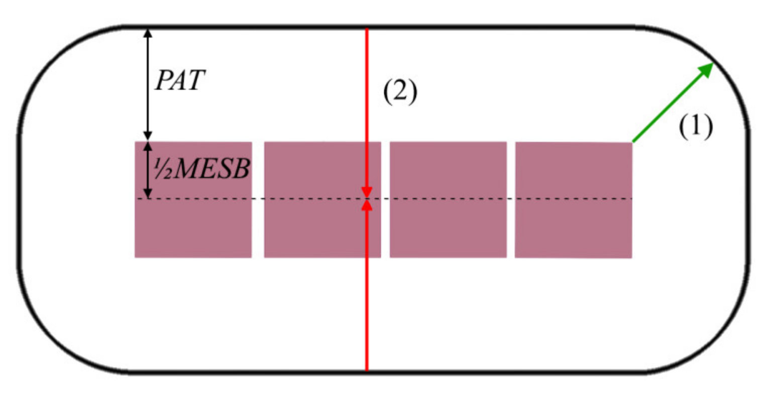
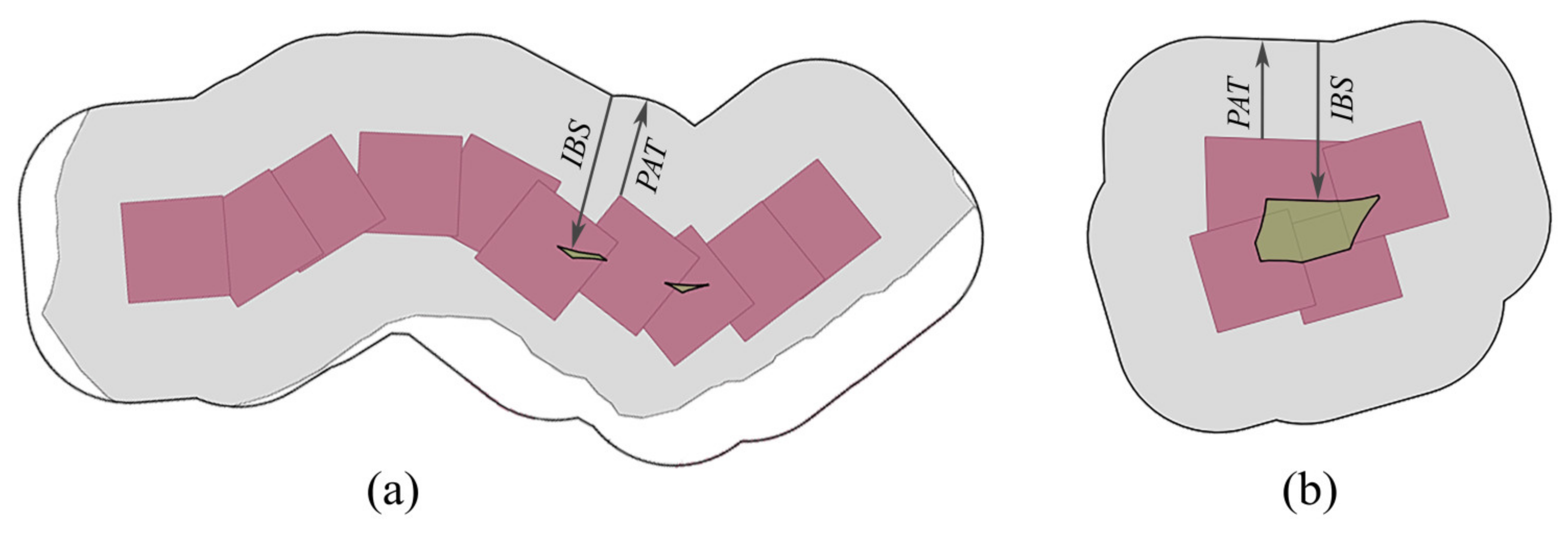
There are various and usually complex approaches for building pattern detection and characterization [20,21,22,23,24]. Particularly, linear (i.e., collinear and curvilinear) patterns need a special approach because they are more salient and more prone to distortion than other kinds of pattern [20]. To this end, a practical method is proposed and implemented here to detect the zones with buildings forming linear patterns and to preserve those patterns as far as possible by narrowing the zones. This method takes into account the PAT and the minimum edge of the smallest buildings (MESB), i.e. 0.5 mm (25 m for 1:50k) [18]. The following steps are applied to detect the zones with a linear pattern (Figure 2 and Figure 3):
  • The PAT-size-dissolved buffer of the buildings is generated. The size of the buffer was chosen equal to the PAT to obtain smoother geometry containing the respective building group.
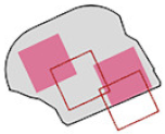
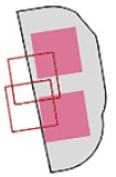
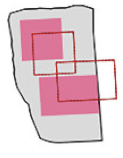
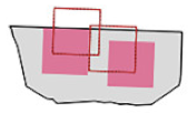
  • The inward (negative) buffer of the resulting polygon is generated. For the perfectly aligned buildings forming linear patterns, the inward buffering process returns an empty geometry as can be seen in Figure 2. Since most of the patterns do not consist of perfectly aligned buildings, tolerance value (t) is used to be able to detect them and hence the inward buffer size (IBS) was chosen equal to (PAT + ½MESB + t) (e.g., 40 m for 1:50k). According to our preliminary trials, t was chosen as 2.5 m.
  • If the area of final polygon is less than 25 sq m (i.e., 0.01 sq mm at 1:50k) or there is no polygon left, it is then assumed that a linear pattern exists in the zone (Figure 3). If the final polygon is a multi-polygon, the area of greater part is taken into account.
The narrowed zones are obtained with the following steps for the linear patterns:
  • The inward buffer of the PAT-size-dissolved buffer is generated. The size of the buffer was chosen to be 5 m less than the PAT (i.e., 20 m) to create a suitable movement space for the buildings (Figure 4a).
  • The areas between the buildings at the both ends of the group and the boundary of the generalization zone (Figure 4a) are included in the final polygon (Figure 4b).

3.3. Determination of Displacement-Feasible Zones

Displacement usually follows individual and other contextual generalization operations. After the generalization zones are created, they are analyzed in terms of zonal building density ( D n s G Z ) to decide their feasibility for displacement (Equation (1)). If the density is not high, displacement is performed.
On the other hand, if the conflicts cannot be resolved at the first attempt, the number of buildings is reduced with typification/elimination (see specific steps of the inner displacement in Section 3.6.3) and then the displacement is repeated. During this process, an additional constraint about the number of buildings is imposed. Accordingly, the number of the buildings is not permitted to fall below the acceptable threshold (i.e., half of the initial number of buildings) (after [25]).
In short, the displacement can usually be applied without reducing the number of buildings if the density is low or is applied after typification/elimination if the density is medium. Due to the variety of the spatial contexts, it is difficult to identify the exact limits of the density that is valid for all of the zones. Therefore, the limit of high density was determined as 85% after some trials since the highly dense zones are subject to amalgamation/aggregation. In other words, the displacement was applied in the zones with a density less than 85%.
D n s G Z = 1 A G Z i = 1 n B A i
where A G Z is the area of the generalization zone, A i is the area of a building, n B is the number of buildings in a generalization zone.

3.4. Generation of a Grid Point Set for the Zones

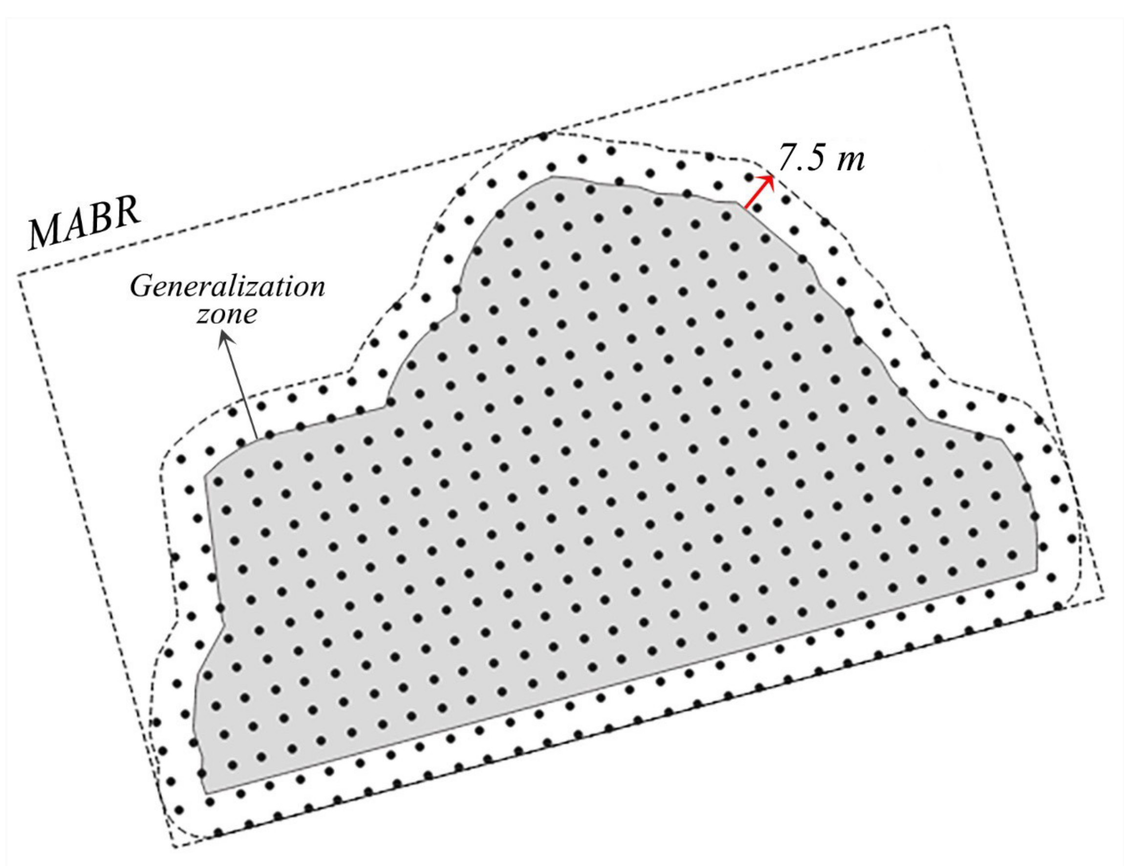
A grid point set is generated to investigate the suitability of different locations in the zone for the displacement of buildings. It is generated at the intervals of 5 m (i.e., 0.1 mm at 1:50k) by means of a minimum area bounding rectangle (MABR) of 7.5 m buffered zone geometry by adjusting the spaces along the edges of the MABR (Figure 5); 7.5 m buffer was created to increase the possibility of locating buildings near the zone boundary so that a minimum distance constraint could be resolved more easily.
As a result of preliminary trials, it was observed that a wider grid interval caused an insufficient amount of base points set to represent a building when its minimum dimensions were considered while a narrower interval did not contribute significantly to the solution and negatively affected the processing speed.

3.5. Grid Point Weighting

Density values of all grid points are computed with kernel density estimation (KDE) based on the base points. Points falling into the buildings (i.e., base points) among the grid points are used to represent the buildings. Reciprocals of the KDE values are then assigned to the points as weights. Thus, the further away the grid points are from the base points representing buildings, the higher their weights become. From the displacement aspect, the higher the weight of a point, the more feasible that location is assumed.
KDE is a frequently employed technique used to transform a discrete distribution of (base) points to a continuous density surface. It preserves the density characteristics of the points in a way that areas that have lots of points receive higher density values than areas that have fewer points [26]. It is calculated with Equation (2) [27].
g x , y = 1 h 2 i = 1 n B P K d i h
where n B P is the number of base points in a generalization zone, g x , y is the estimated density at a location x , y , d i is the Euclidean distance from location x , y to a base point, h is the bandwidth, and K is the kernel function.
It is required to determine a bandwidth and a kernel function before applying KDE. The smoothness of the density surface depends on these parameters. It is usually difficult to select an appropriate bandwidth. In many cases, it is experimentally decided. Similarly, the kernel function selection is also experimental. The most preferred function is the Gaussian kernel. When two parameters are compared, the selection of bandwidth is more critical than the selection of the kernel function [26,27].
In this study, the Gaussian kernel function was used with a PAT-size (i.e. 25 m for 1:50k) bandwidth. These parameters were determined experimentally.

3.6. Displacement

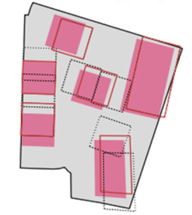
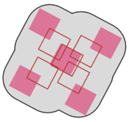
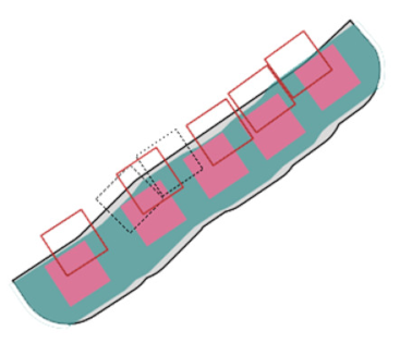
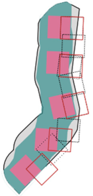
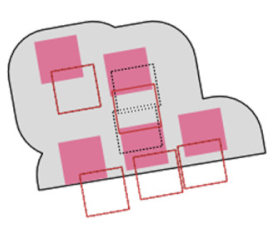
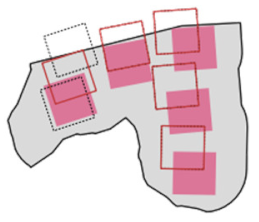
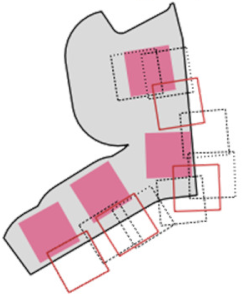
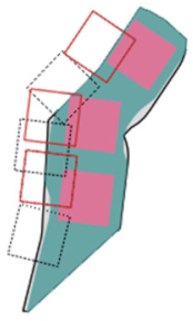
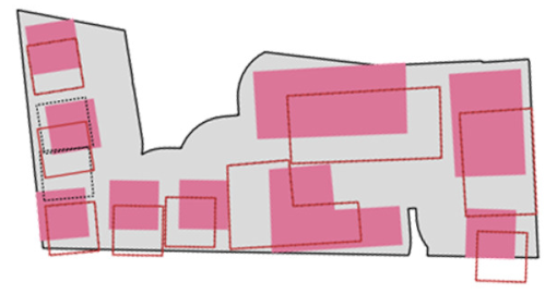
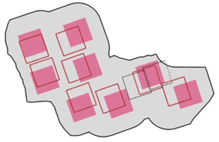
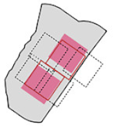
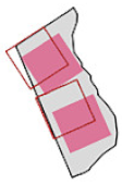
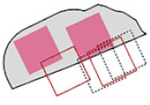
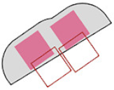
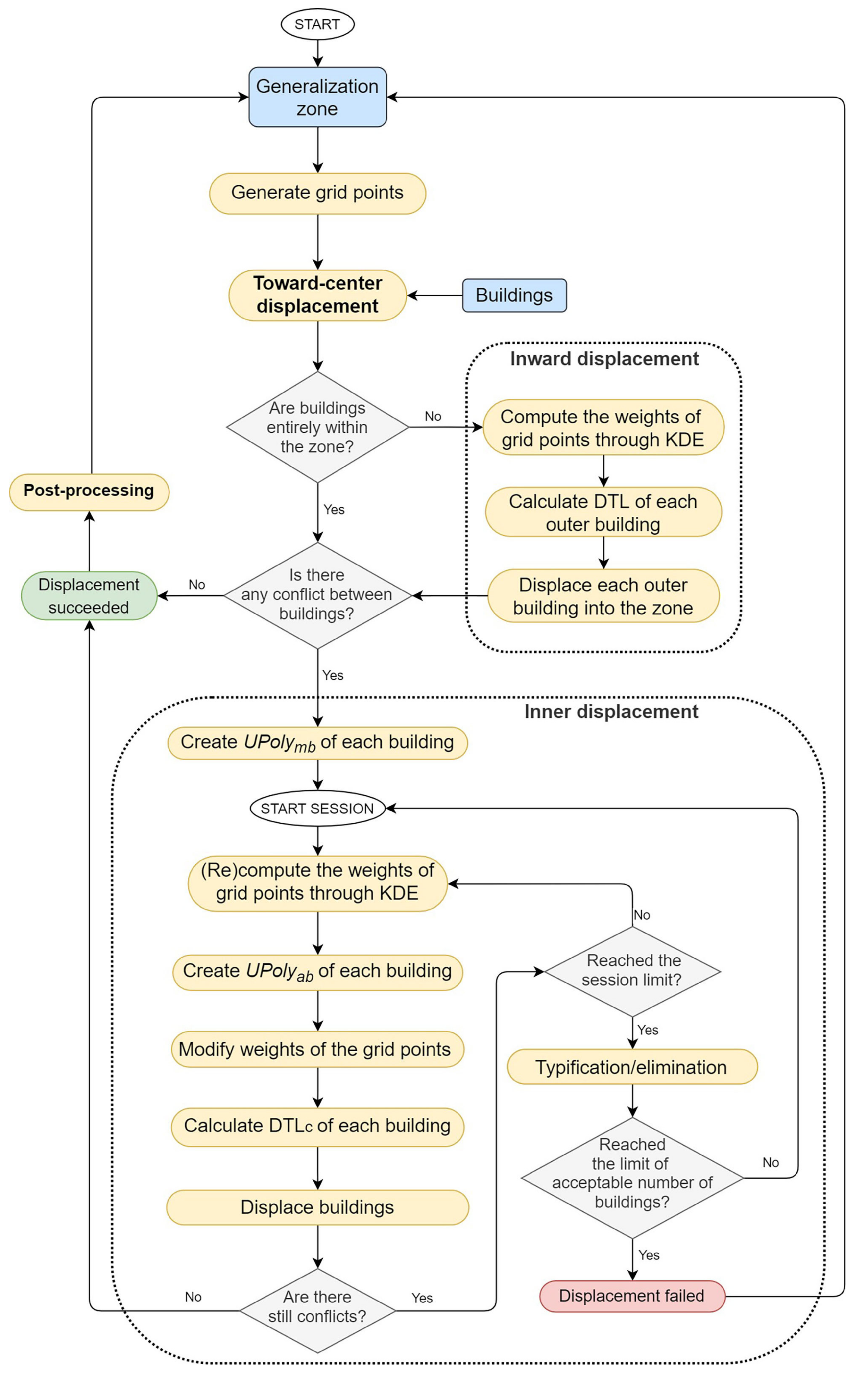
The displacement approach is performed in three main phases (Figure 6). First, all buildings are collectively displaced in a way in which their weighted average position is moved toward the zone’s centroid (toward-center displacement). Then, the buildings that intersect with the zone boundary, if any, are re-displaced so that they are located within the zone (inward displacement). Finally, buildings are iteratively moved to suitable locations in the zone (inner displacement). In addition, the post-processing is applied to slightly improve the positional accuracy.
During the displacement, positional change is restricted by the positional accuracy constraint and thus its violation is not permitted. The process is terminated when the minimum distance constraint is satisfied between all buildings or the session limit of the inner displacement is reached or the final number of buildings falls below the limit of acceptable threshold.
On the other hand, spatial patterns and relationships do not have a direct effect over the displacement operation. However, those are tried to be preserved indirectly by using the following mechanisms:
  • The zones restrict the area that the buildings can move.
  • The zones with linear patterns are highly narrowed to preserve the patterns as far as possible.
  • Positional accuracy constraint (i.e., PAT = 25 m) limits the positional changes of the buildings.
  • Toward-center displacement carries the buildings toward the centroid of the generalization zone collectively to mainly reduce or resolve the conflicts with roads.
  • During inner displacement, in every session (see Setion 3.6.3), all buildings are displaced by small amounts proportional to their distances to their computed target locations.

3.6.1. Toward-Center Displacement

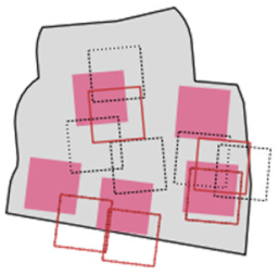
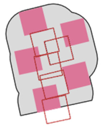
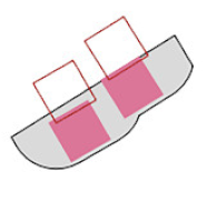
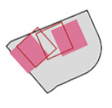
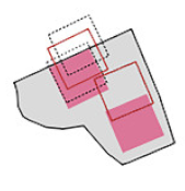
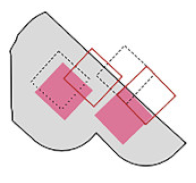
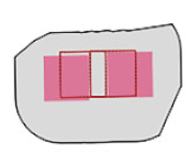
In this phase, the buildings are displaced collectively in a way that their area-weighted average centroid (Equations (3) and (4)) relocated at or near the centroid of the zone but the amount of displacement cannot exceed the PAT. Thus, the possibility of deterioration of the spatial relations among the buildings is reduced. Furthermore, the buildings are brought to more suitable locations in terms of their movement to empty spaces, as well as their conflicts with roads being reduced (Figure 7a) or resolved (Figure 7b). On the other hand, some buildings may move slightly outside of their zones after this process.
x w a c = i = 1 n B x i × A i / i = 1 n B A i
y w a c = i = 1 n B y i × A i / i = 1 n B A i
where n B is the number of buildings in a generalization zone, x w a c and y w a c are the area-weighted average centroid coordinates of the buildings in a zone, x i and y i are centroid coordinates of a building, A i is the area of a building.

3.6.2. Inward Displacement

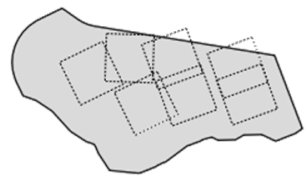
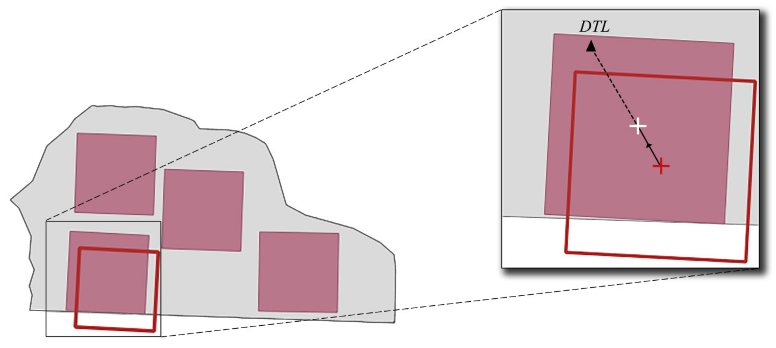
Inward displacement individually moves each building located fully or partially outside the zone into the zone and is applied if the buildings are not completely within the zone after the toward-center displacement (as seen in Figure 7a). New location of the buildings is determined by means of the following steps:
  • Directional target location (DTL) ( x D T L ,   y D T L ) is obtained from grid points within the polygon generated with the intersection of PAT-size buffer of the building and the zone (Equations (5) and (6)). These points are called inner grid points.
    x D T L = i = 1 n P x i × w 0 , i / i = 1 n P w 0 , i
    y D T L = i = 1 n P y i × w 0 , i / i = 1 n P w 0 , i
    where n P is the number of inner grid points, x D T L and y D T L are the coordinates of DTL, x i and y i are coordinates of an inner grid point, w 0 , i is weight of an inner grid point, computed with the KDE.
The buildings are displaced iteratively in small steps (0.5 m) toward DTL until they are entirely within the zone. The process is applied to all buildings located outside the zone (Figure 8). A building is eliminated if it is impossible to completely move it into the zone because of the size or shape of the zone.

3.6.3. Inner Displacement

Inner displacement is performed after all buildings have been moved into the zone if there is minimum distance conflict between them. The logic behind this process is to displace all buildings in iterative sessions by finding more feasible locations each time as long as the conflicts between the buildings remain unresolved and other termination criteria mentioned in Section 3.6 are not reached.
The session here denotes the displacement of all buildings in the zone once. In the beginning of each session, the weights of the points are updated with the KDE and then modified by the criteria explained below. The displacement order is not important because all buildings in a zone are displaced in each session. In addition, buildings are allowed to move beyond the zone in to a small extent (i.e., 2.5 m) unless the extent of displacement does not exceed PAT, since some buildings cannot use the maximum allowed displacement right due to the zone restriction.

Building-Specific Modification of Grid Point Weights

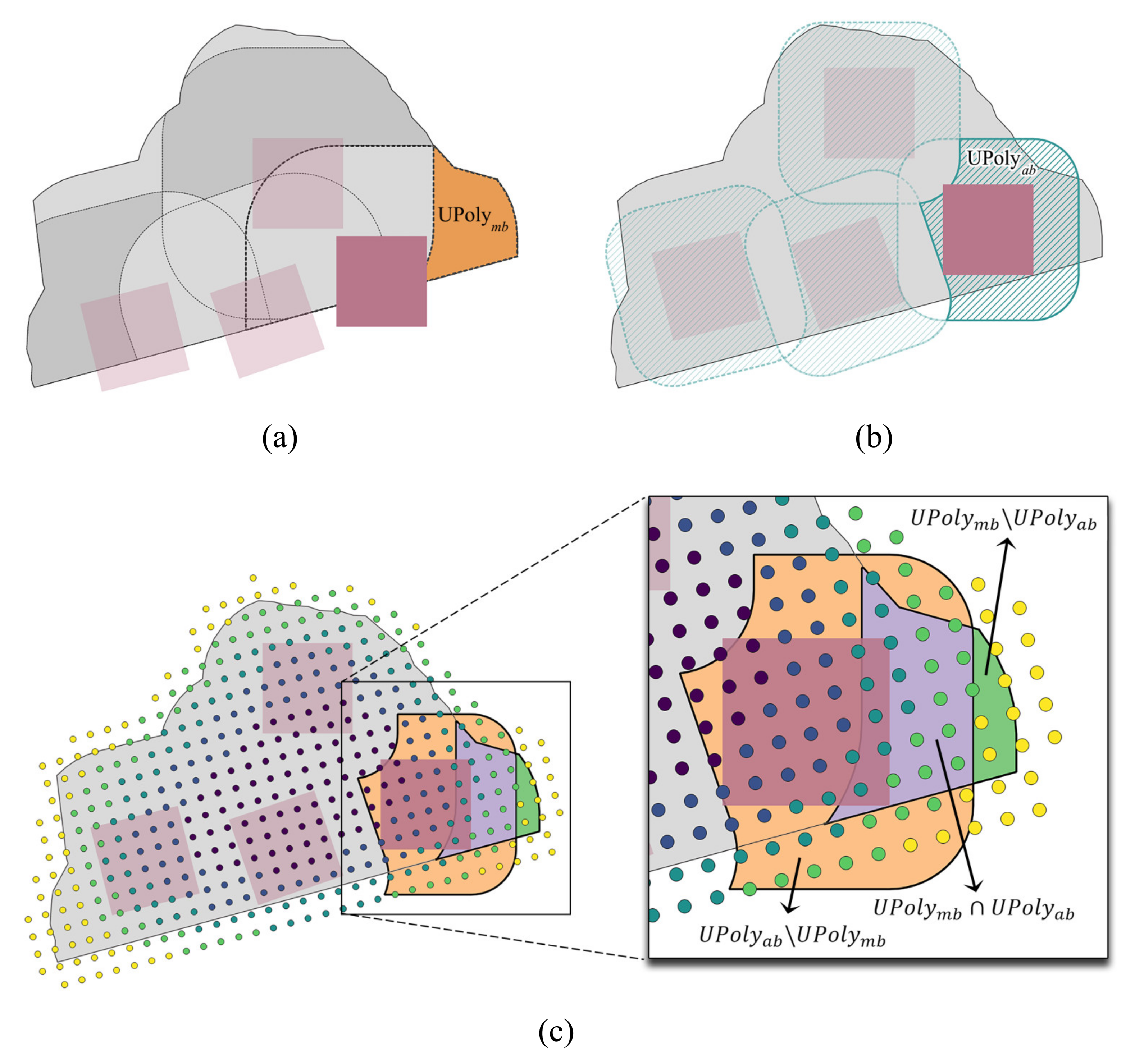
Initial weights of the grid points obtained with KDE are modified for each building to increase the effect of its relevant points when calculating the DTL. The relevant points of a building are identified by means of buffering. For this purpose, two kinds of buffers are created for every building:
  • Unique polygon of a main buffer (UPolymb): the difference polygon between the PAT-size buffers of a respective building and other buildings delimited by the zone (Figure 9a). This kind of buffer is created once before the displacement when the buildings are at their initial locations. The size of the buffer chosen is equal to the PAT because the buildings do not have to move outside of these buffers. The difference in polygon corresponds to the unique area where the other buildings cannot be moved. In other words, it is the most feasible area to displace a building; therefore, the weights of the points that fall within this area are increased.
  • Unique polygon of an auxiliary buffer (UPolyab): the difference in polygon between the half-PAT-size (i.e., 12.5 m) buffers of a building and other buildings (Figure 9b). The size of the buffers was determined after some trials. This kind of buffers are generated in each iteration immediately before displacing buildings. They are not clipped by the zone to be able to involve points around it as well. The reason for creating those buffers is to increase the weight of points that are not located in the intersection of the half-PAT-size buffers of close buildings. In this way, it is possible to move these buildings away from each other and to resolve the conflict between them in general.
The modified weight of a grid point w m is determined by whether it is contained by one or two of the unique polygons (Figure 9c) using Equation (7), where w 0 is the initial weight of a grid point computed with the KDE:
w m = w 0 2 p U P o l y m b \ U P o l y a b   o r   p U P o l y a b \ U P o l y m b 2 w 0 2 p U P o l y m b U P o l y a b w 0 o t h e r w i s e

Specific Steps of the Inner Displacement

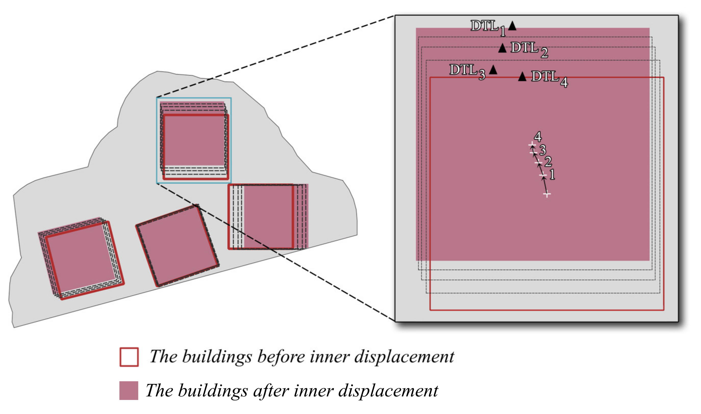
The following steps are applied for the inner displacement (Figure 10):
  • The distance between the current D T L ( D T L c ) (Equations (8) and (9)) and the centroid of each building is calculated. D T L c is computed in each session again for each building.
    x D T L c = i = 1 n x i × w c , i / i = 1 n w c , i
    y D T L c = i = 1 n y i × w c , i / i = 1 n w c , i
    where x D T L c and y D T L c are the current coordinates of D T L , x i and y i are coordinates of a grid point, w c , i is current weight of a grid point.
  • The amount of displacement for a building is set as one-tenth of the calculated distance in the previous step and accordingly each building is displaced toward D T L c in each session. This amount is kept small in order to avoid immediate deterioration of spatial relationships between buildings.
  • The displacement process can continue until the maximum permitted number of sessions is reached. After some trials, it was determined to be 40.
  • One of the buildings is eliminated or typified if there is still a conflict when the sessions are over. This building is one of the two buildings that have the most conflict (i.e., the nearest ones) prior to inner displacement, either the smaller one if their areas are different, or one of them if they have an equal area and same shape (compactness). The typification/elimination process is performed with the area-weighted recentering and the inner displacement process is repeated with the remaining buildings by starting from their initial positions.
  • After the typification/elimination, if the number of buildings is less than half of the initial number of buildings, the displacement process is cancelled in this zone and a solution must be found with another generalization operation.

3.6.4. Post-Processing

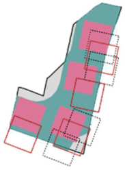
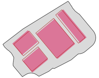
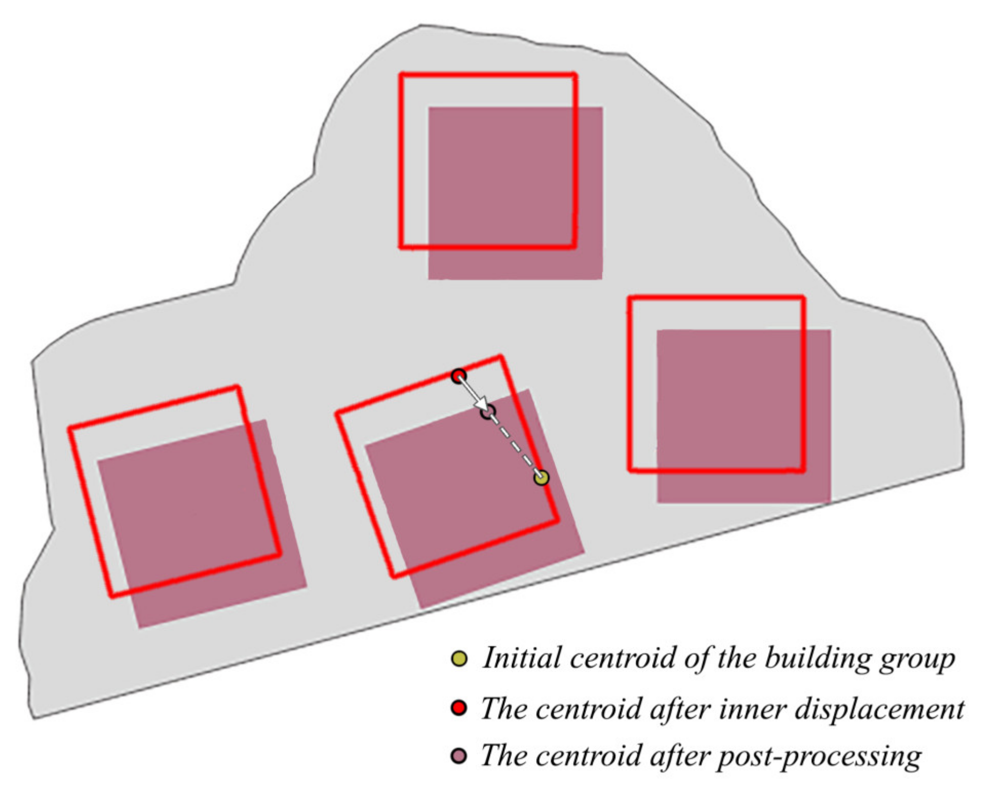
After the inner displacement, as post-processing, the buildings are collectively shifted back towards the initial centroid of the building group in small steps to decrease the amount of the positional difference (Figure 11). The collective shift process is terminated as soon as any building touches it with the zone boundary.

3.7. Evaluation of the Displacement Quality

Three constraints mentioned before are taken into account in terms of the displacement quality. It should be noted that all constraints are applied in the zones. Therefore, the zones restrict the movement of buildings and mainly help to preserve proximal relationships between the building groups.
The first two constraints, i.e., the minimum distance and positional accuracy constraints are enforced and required to be satisfied during the displacement. The third constraint is not directly enforced and tried to be satisfied indirectly as explained in Section 3.6.
The quality is scored in a range of 1–5 and is ranked in a range from “very bad” to “very good”. If the minimum distance constraint is not fully satisfied in a zone, its quality is scored to be 1 and is ranked to be “very bad”. Another operation such as elimination (only for single buildings), amalgamation, or aggregation should be considered for the zones where the conflicts remain unresolved.
As the first two constraints are ensured to be satisfied, the displacement quality is evaluated based on the spatial relationships of the buildings before and after displacement. The remaining scores, i.e., from 2 to 5 are produced accordingly. In this scope, some measures are proposed in this study, depending on the number of buildings.
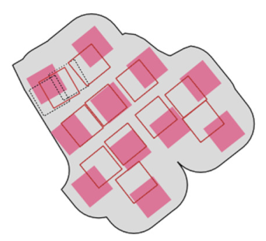
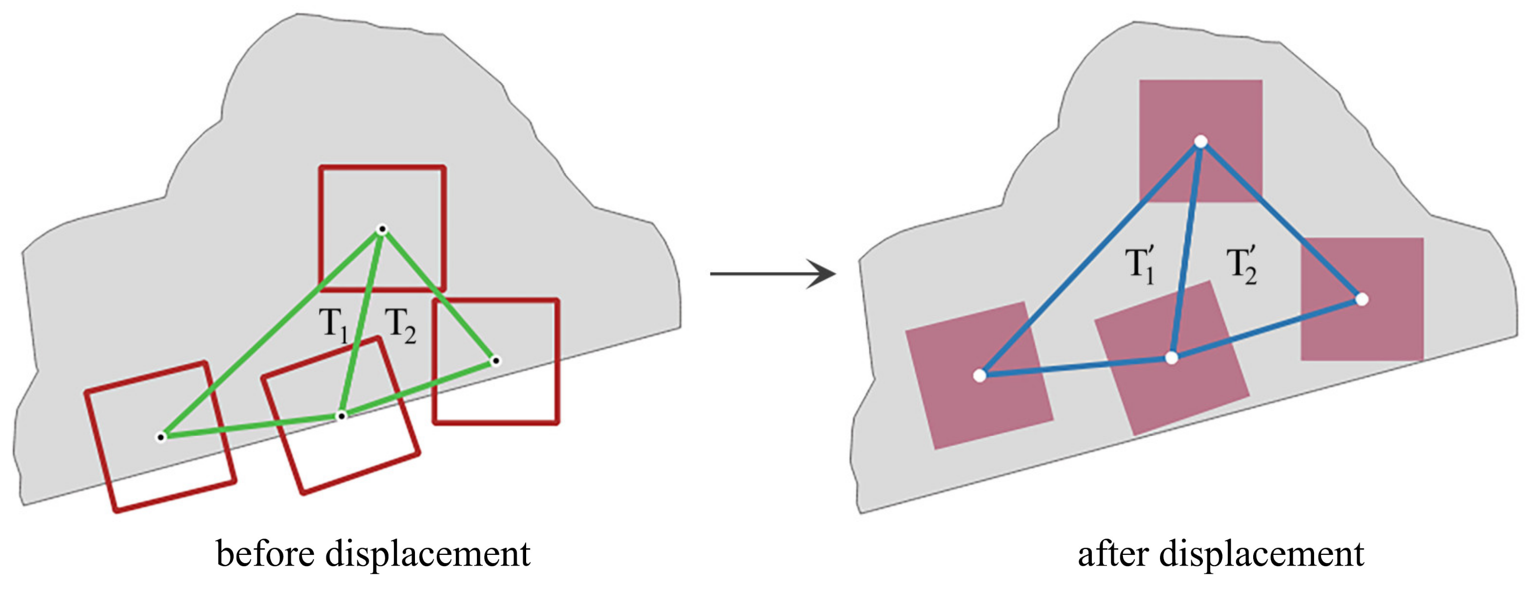
For the zones with a minimum of three buildings, Delaunay triangulation is generated using the centroids of the initial buildings in the zones. After the displacement, new triangles are also generated for the same triples of buildings (Figure 12).
Three measures are proposed to evaluate the quality of the building displacement, which compare the initial and final states of the corresponding triangles (e.g., T 1 and T 1 ) from angle, length, and shape aspects. For the angles, the angle comparison measure ( m α ) is introduced and computed based on the standard deviations (Equation (10)). For the lengths, the length comparison measure ( m l ) is introduced and computed based on the ratio of the standard deviations to the averages (Equation (11)). For the shapes, the compactness comparison measure ( m c ) is introduced and computed based on the areas and the perimeters (Equation (12)). Compactness (a.k.a. circularity) was preferred as it is one of the most-used indices in the practical shape analysis [28,29].
m α =   1 n i = 1 n σ α , i σ α , i
m l =   1 n i = 1 n σ l , i μ l , i σ l , i μ l , i
m c =   4 π n i = 1 n A i P i 2 A P i 2
where n is the number of triangles in a zone, σ α and σ α are the standard deviations of the interior angles of initial and final triangles (IFTs), respectively, σ l and σ l are the standard deviations of the edge lengths of IFTs, μ l and μ l are the average lengths of the edges of IFTs, A and A are the areas of IFTs, P and P are the perimeters of IFTs.
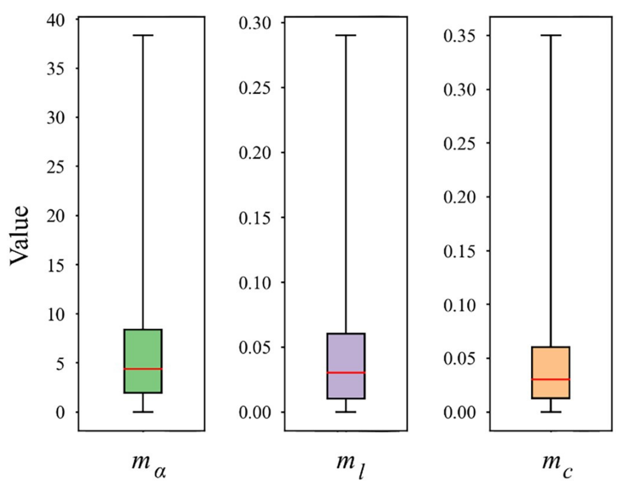
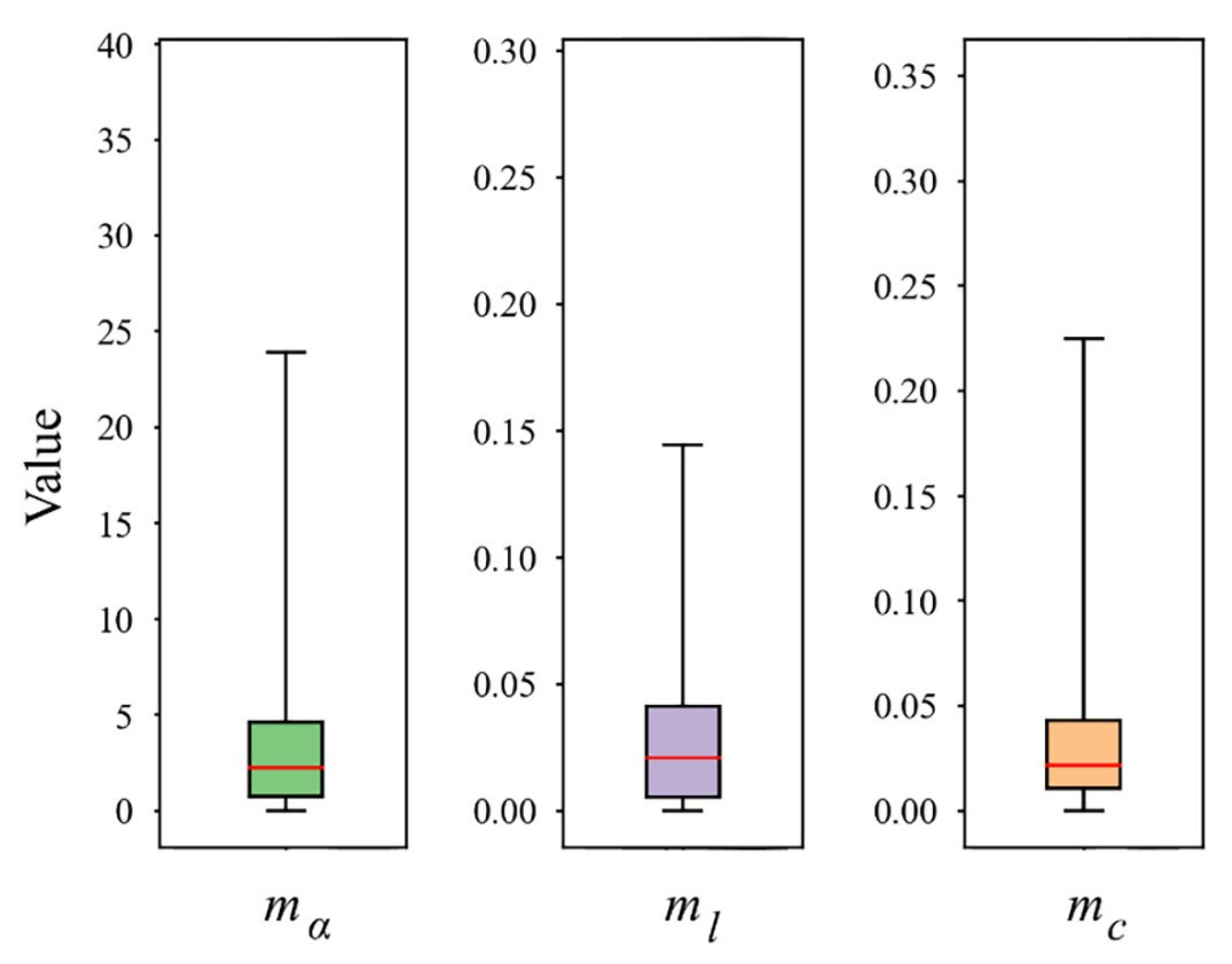
The quality scores of angle ( q s α ) , length ( q s l ) and compactness q s c comparison measures are assigned by the following criteria, respectively (Equations (13)–(15)). For obtaining the criteria, a visual assessment of the displacement quality was made and a score was assigned to the zones. Accordingly, the box plots of the scores were generated for the measures. The interdecile ranges of the scores (the values between 10th and 90th percentiles) were regarded to determine the threshold values for the scores to prevent the negative effect of outliers as much as possible. In this way, the criteria of the measures were yielded.
The threshold values of the measures were determined depending on the number of the buildings ( n b ) in a zone. According to the scores assigned with the visual assessment, it was needed to use different threshold values for the zones with three buildings. For example, the score was 4 for the buildings shown in Figure 13 according to the visual assessment, while the score was 3 according to the general thresholds. Therefore, the threshold values were adjusted appropriately for the zones with three buildings based on their boxplots.
q s α = 5 , m α 6.5 °   i f   n b > 3 , m α 6.45 °   i f   n b = 3   4 , 6.5 ° < m α 14.3 °   i f   n b > 3 6.45 ° < m α 26 °   i f   n b = 3 3 , 14.3 ° < m α 31.5 °   i f   n b > 3 26 ° < m α 47.2 °   i f   n b = 3 2 , 31.5 ° < m α   i f   n b > 3 47.2 ° < m α   i f   n b = 3
q s l = 5 , m l 0.045   i f   n b > 3 m l 0.085   i f   n b = 3 4 , 0.045 < m l 0.1   i f   n b > 3 0.085 < m l 0.11   i f   n b = 3 3 , 0.1 < m l 0.16   i f   n b > 3 0.11 < m l 0.165   i f   n b = 3 2 , 0.16 < m l   i f   n b > 3 0.165 < m l   i f   n b = 3
q s c = 5 , m c 0.045   i f   n b > 3 m c 0.052   i f   n b = 3 4 , 0.045 < m c 0.1   i f   n b > 3 0.052 < m c 0.23   i f   n b = 3 3 , 0.1 < m c 0.27   i f   n b > 3 0.23 < m c 0.36   i f   n b = 3 2 , 0.27 < m c   i f   n b > 3 0.36 < m c   i f   n b = 3
Finally, the quality score ( Q S ) is calculated by averaging the scores of those measures derived based on the above criteria (Equation (16)). For the measures, equal weights were used since their individual performances according to the visual assessment were similar. Accordingly, the quality rank ( Q R ) is assigned to the zones as explained above.
Q S = ( q s α + q s l + q s c ) 3
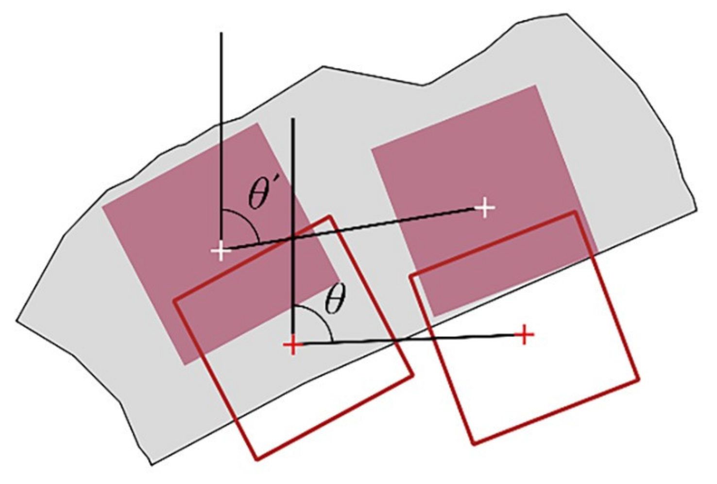
If the number of buildings is two, the azimuth comparison measure ( m θ ) is used that finds the azimuth difference between the connection lines generated between the centroids of the buildings and calculated with Equation (17) (Figure 14) and the scores are assigned by Equation (18).
m θ =   θ θ
Q S = 5 , m θ 10 ° 4 , 10 ° < m θ 13 ° 3 , 13 ° < m θ 30 ° 2 , o t h e r w i s e
For single buildings, the quality is evaluated depending on whether a building can be moved into the zone. To be specific, it becomes either 1 (very bad) if there is still a conflict, or 5 (very good) otherwise.

4. Results and Discussion

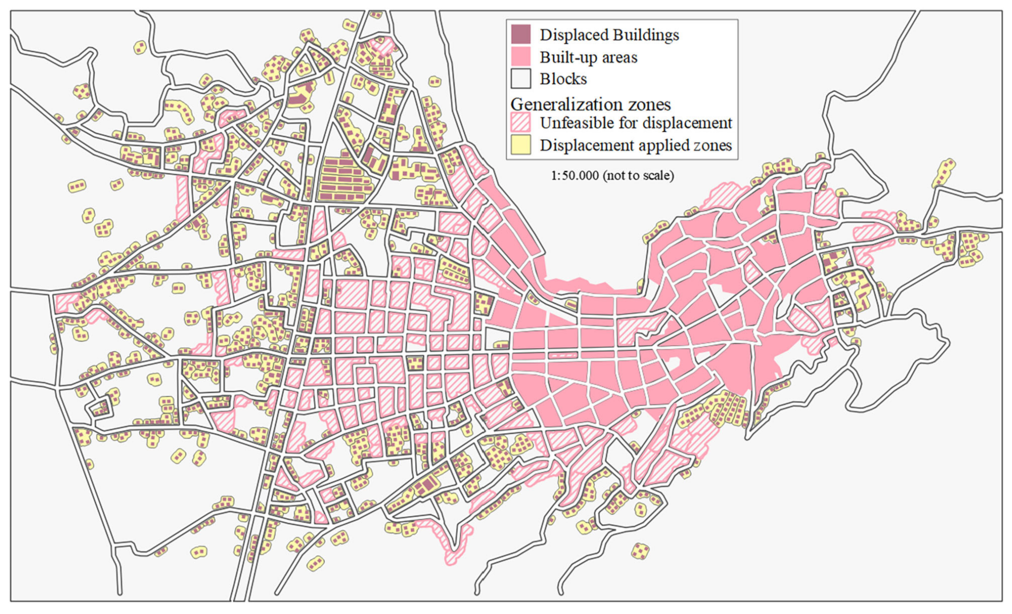
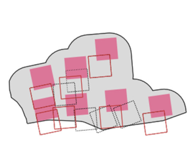
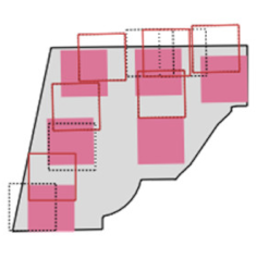
In the study area, 757 generalization zones were generated and 60.23% (456 out of 757) of the zones were found to be feasible for the displacement. The total number of the buildings was 4586. Among them, 1569 buildings were in the displacement-feasible zones. After the displacement, the number of buildings was reduced to 1194 as a result of typification/elimination (see Appendix A). The Supplementary Material, Video S1 shows how the displacement method works.
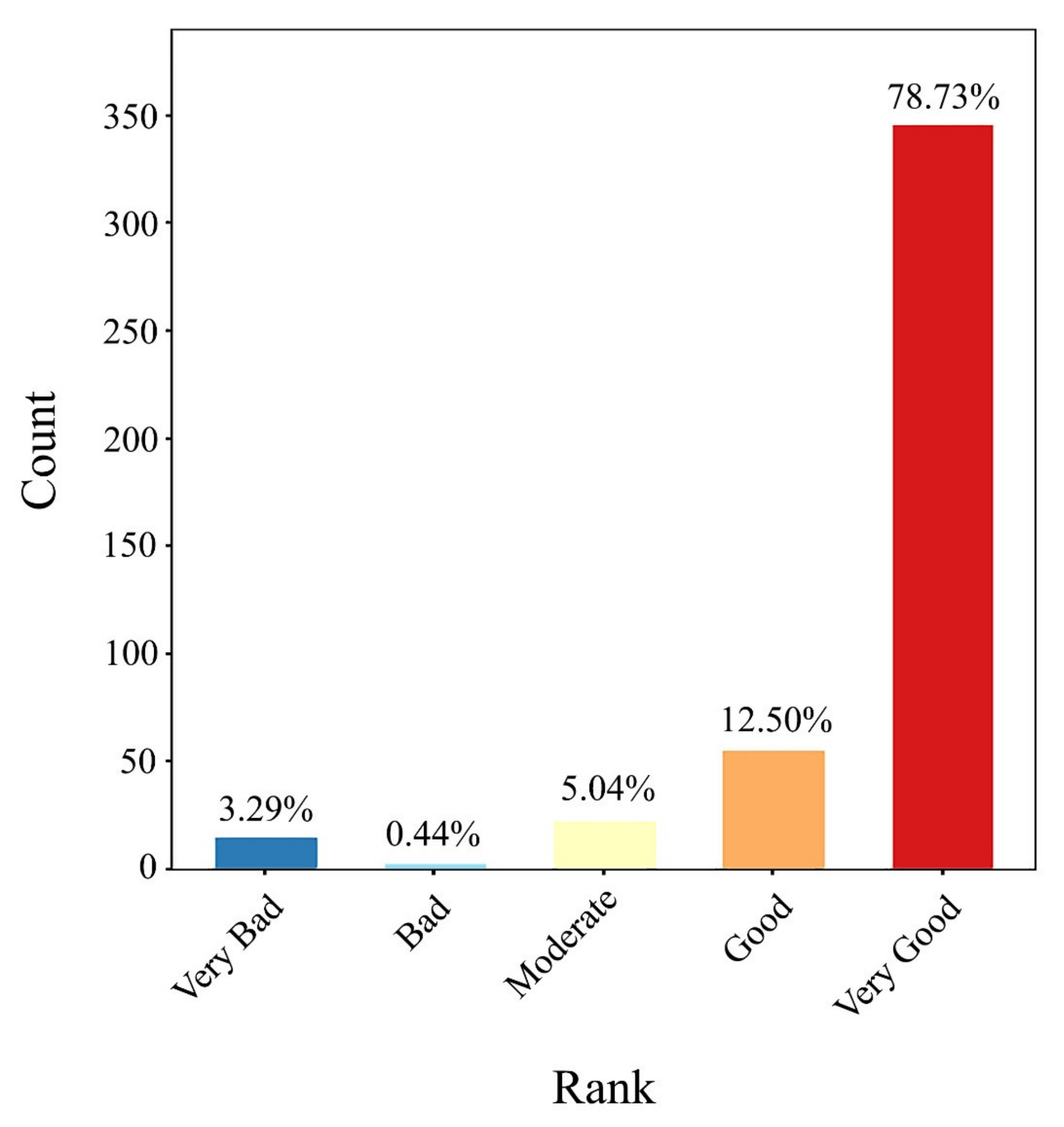
According to the quality evaluation of the zonal displacement, the proposed approach yielded quite satisfactory results (see Appendix B) and 78.73% of the zones were ranked “Very Good” in terms of displacement quality. This was followed by “Good”, “Moderate”, “Bad” and “Very Bad” rankings at the rates of 12.50%, 5.04%, 0.44% and 3.29%, respectively (Figure 15).
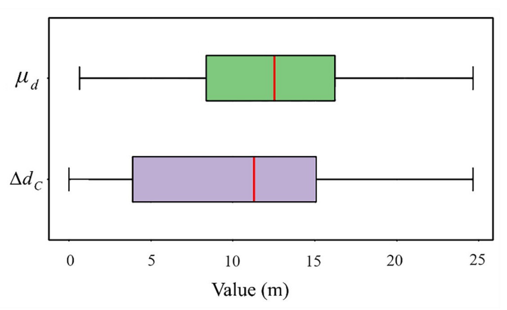
Average zonal building displacement amounts ( μ d ) ranged between 0.63 m and 24.64 m while the median value was 12.52 m and the 10th and 90th percentiles ranged from 4.38 m to 19.31 m, corresponding to 80% of the values. The zonal displacement amounts of building group centroids ( Δ d C ) ranged between 0.00 m and 24.64 m, while the median value was 11.22 m and 10th and 90th percentiles were 1.31 m and 17.86 m, respectively (Figure 16). These findings showed that the positional accuracy constraint was satisfied completely in the zones where the conflicts were resolved (i.e., except for the ones with a “Very Bad” ranking). The displacement amounts are usually greater in the zones next to the roads because the enlargement of the symbol sizes of the roads in addition to the buildings increases the amount of conflicts.
The angle comparison measure yielded values in the range of 0.00–38.33, while the median value was 4.36 and the 10th and 90th percentiles were 0.65 and 12.77, respectively. The length comparison measure got values in the range of 0.00–0.29 while the median value was 0.03 and the 10th and 90th percentiles were 0.00 and 0.10, respectively. Compactness comparison measure got values in the range of 0.00 to 0.35, while the median value was 0.03 and the 10th and 90th percentiles were 0.01 and 0.10, respectively (Figure 17). For all of the measures, the median values are in the range of “Very Good” ranking while the 90th percentiles are in the range of “Good” ranking. These findings showed that the proposed approach, in many cases, was able to preserve the spatial relationships among buildings in the zones.
The quality evaluation criteria pertaining to the spatial relationships among buildings were derived by means of quantitative analysis of the comparison measures based on the scores obtained with the visual assessment of the displacement results. Accordingly, the threshold values were obtained for the quality ranks. Meanwhile, it was recognized that the different threshold values were needed in the case of single triangle (i.e., three buildings) according to the scores assigned with the visual assessment.
For the zones with two buildings, the azimuth comparison measure was used alone because another potential measure, namely the length comparison, did not produce meaningful results that could aid in evaluating the quality.
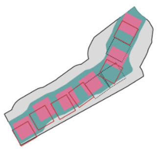
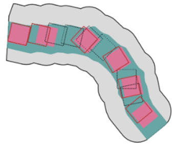
Concerning the linear patterns, the angle comparison measure yielded values in the range of 0.00–23.25, while the median value was 2.16 and the 10th and 90th percentiles were 0.19 and 6.88, respectively. The length comparison measure got values in the range of 0.00–0.14, while the median value was 0.02 and the 10th and 90th percentiles were 0.00 and 0.05, respectively. Compactness comparison measures got values in the range of 0.00–0.21, while the median value was 0.02 and the 10th and 90th percentiles were 0.00 and 0.07, respectively (Figure 18). Eighty four percent of the linear patterns were ranked “Very Good”, while 15% and 1% of them were respectively ranked “Good” and “Moderate” according to the quality evaluation criteria. These findings show that the proposed approach can quite effectively preserve the linear patterns of buildings in the zones. On the other hand, some zones contain mixed patterns. In that case, our method was not able to detect specific patterns. Clearly speaking, linear and unstructured patterns may be together in a zone due to their closeness and the linear patterns cannot be distinguished in this case. For all of the measures, the median values and 75th percentiles are in the range of “Very Good” ranking. These findings show that the proposed approach is largely able to preserve the linear patterns of the buildings after displacement.
Our approach produces zonal displacement solution and does not consider the conflicts arisen between the zones after displacement. Therefore, in case of occurrence of the conflicts among the buildings belonging to the neighboring zones, the respective buildings may be typified/eliminated. In addition, the semantic differences of the buildings were not taken into account in this study. No or very little displacement should/must be applied to the significant buildings. For example, the religious buildings on which trigonometric points are found should/must not be displaced if possible. Furthermore, the semantic differences should/must be regarded during typification/elimination.
The proposed approach is quite practical and can be developed in a GIS environment by programming without too much effort. It can produce quite successful results for zonal building displacement in many cases. In this context, zonal grid points weighted through KDE and multiple buffer analysis helped to produce satisfactory displacement results in general by allowing us to select optimal locations for buildings in each session. In other words, this strategy provided incremental improvements of the locations of the buildings. In addition, it was possible to detect linear patterns in the zones quite effectively with a new and very practical method. Furthermore, narrowing the respective zones enabled us to preserve this kind of building pattern. Finally, the displacement evaluation criteria produced largely compatible results with the visual assessment, based on three newly proposed measures focusing on the spatial relationships of the buildings. Meanwhile, the satisfaction of the other constrains (i.e., the minimum distance and positional accuracy) was ensured during the displacement.

5. Conclusions

This article introduced a zonal displacement approach specific to building generalization in medium scale topographic maps. In this context, minimum distance, positional accuracy, and spatial patterns and relationships were taken into account to derive a sufficiently accurate and legible representation at a target scale. The individually generalized buildings and surrounding roads were used as inputs and the spatial conflicts occurring between those objects guided the displacement approach. Specifically, the groups of buildings were obtained with the minimum distance criterion to identify the conflicted buildings in the blocks surrounded by roads. The block area was shared among those groups of buildings by generating generalization zones through Voronoi tessellation and buffering. Thus, the displacement problem was reduced to develop a solution in the generalization zones. Besides, the zones with linear patterns were identified through multiple buffering operations and then narrowed to be able to preserve these patterns. Following that, the buildings were first displaced toward the center of the zone collectively and then inward to the zone individually if they were not fully inside. In order to find optimal locations to displace buildings incrementally, the regular points (i.e., a grid point set) were created for the zones and those points were weighted according to the base points falling into the buildings by means of KDE and buffer analysis. In this way, the displacement direction was identified for each building and all the buildings were displaced by small amounts iteratively in multiple sessions. In each session, the weights of the points are updated to find the suitable locations for the buildings according to current state. The displacement process was terminated when the conflicts were resolved or the limit of the permitted number of sessions or the limit of the acceptable number of buildings was reached. Afterwards, the post-processing is applied to improve the positional accuracy slightly. The quality of the displacement was evaluated based on the constraints. Minimum distance and positional accuracy constraints were analyzed during the displacement and were enforced to be met. Spatial patterns and relationships were evaluated after the displacement through (Delaunay) triangulation if a zone had a minimum three buildings or connection lines if a zone had two buildings by comparing initial and final states of those geometries with the angle, length and shape comparison measures in the former case and an azimuth measure in the latter case. According to the threshold values of the measures, determined by quantitative analysis of the visual assessment results, the zones were scored and ranked with respect to the displacement quality.
In future works, interaction with neighboring zones can be dealt with. Linear patterns can be detected in the zones with mixed patterns if available and the related parts of the zones may only be narrowed to preserve the linear patterns. In addition, more specific kinds of patterns may be detected and displaced accordingly. The quality evaluation method may be improved by comparing corresponding lines and angles of the triangles directly. When the displacement is failed, it may be repeated by setting new parameters for the grid resolution and the KDE bandwidth or the parameter settings may be specific to the generalization zones.

Supplementary Materials

The following are available online at https://www.mdpi.com/2220-9964/10/2/105/s1, Video S1: Examples of the building displacement.

Author Contributions

Conceptualization, Melih Basaraner; Data curation, Kadir Sahbaz; Methodology, Melih Basaraner; Software, Kadir Sahbaz; Visualization, Kadir Sahbaz; Writing—original draft, Kadir Sahbaz and Melih Basaraner; Writing—review and editing, Kadir Sahbaz and Melih Basaraner. All authors have read and agreed to the published version of the manuscript.

Funding

This research received no external funding.

Institutional Review Board Statement

Not applicable.

Informed Consent Statement

Not applicable.

Data Availability Statement

Restrictions apply to the availability of these data. The data are not publicly available due to privacy.

Conflicts of Interest

The authors declare no conflict of interest.

Appendix A

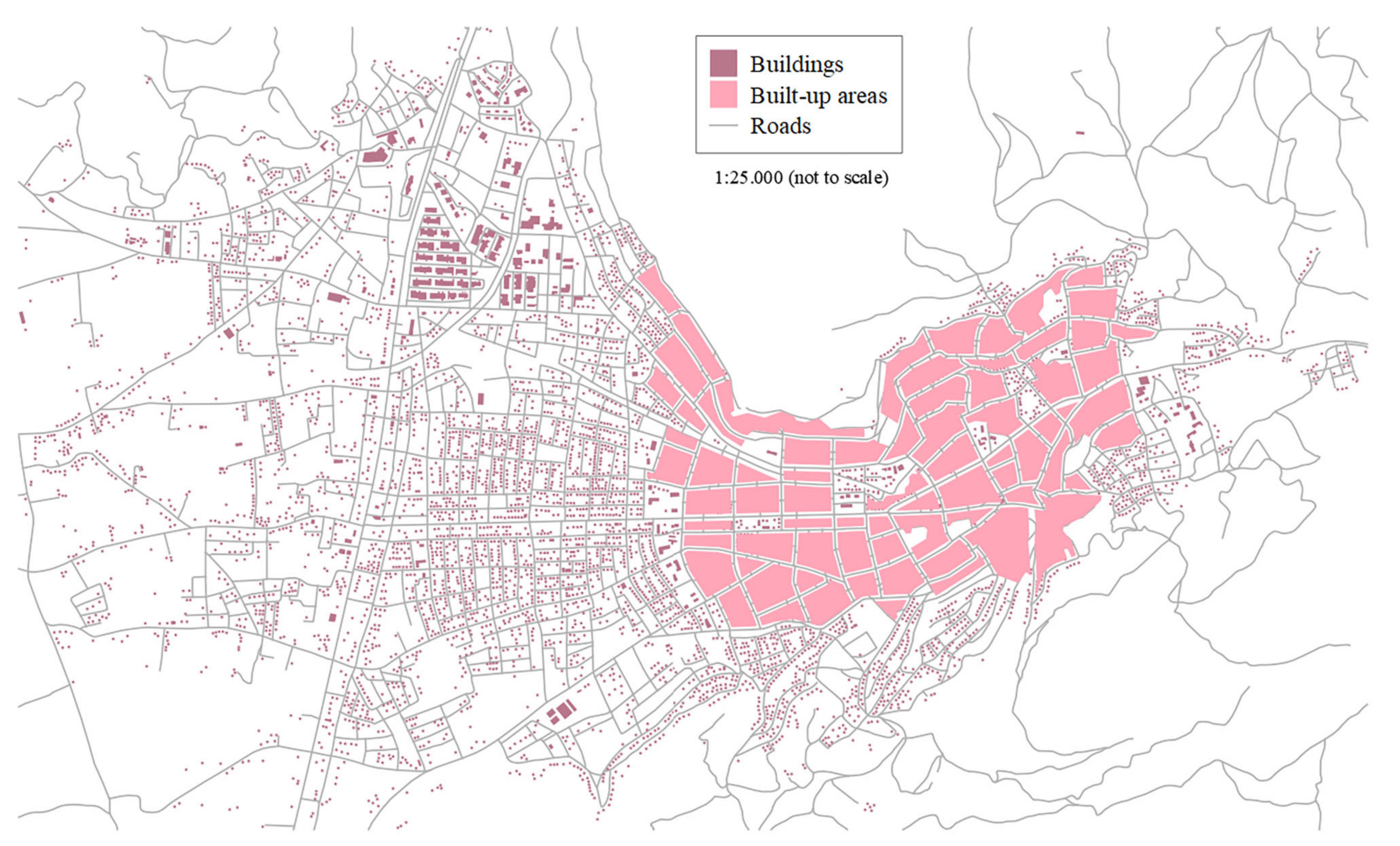
Figure A1. 1:25k topographic map data of the study area.
Ijgi 10 00105 g0a1
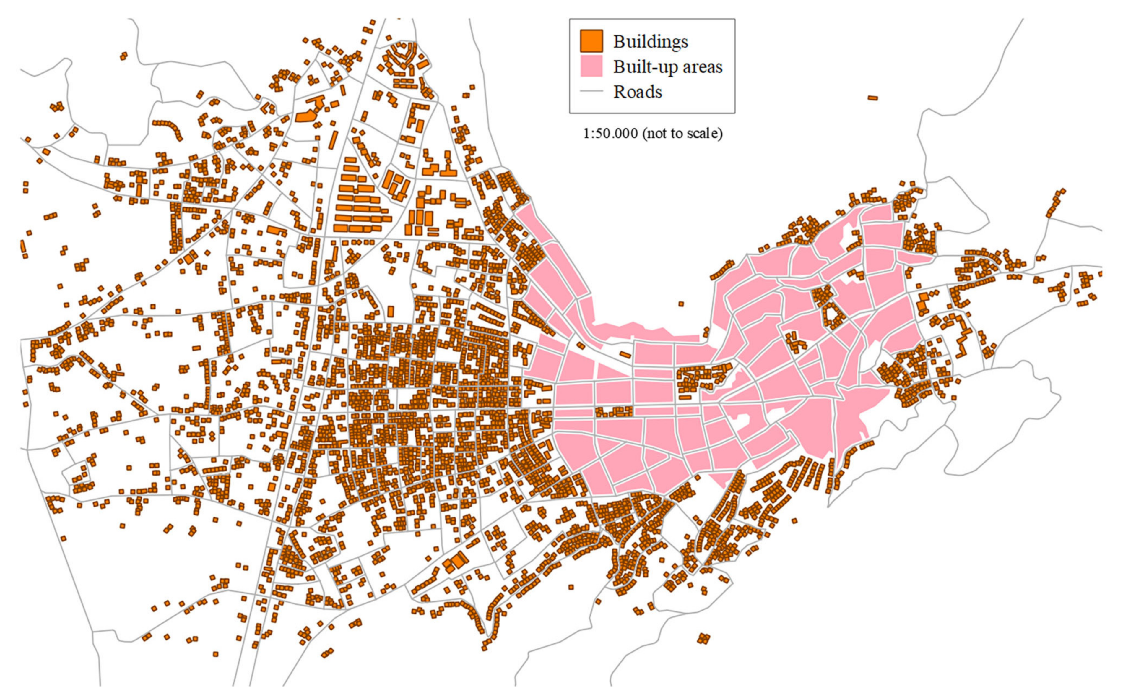
Figure A2. 1:50k topographic map data of the study area after individual generalization.
Ijgi 10 00105 g0a2
Figure A3. 1:50k topographic map data of the study area after displacement.
Ijgi 10 00105 g0a3

Appendix B

Table A1. Examples of the zonal building displacement including quality evaluation. Description of the symbols are as follows: mα: angle comparison measure, ml: length comparison measure, mc: compactness comparison measure, mθ: azimuth comparison measure, µdd: average zonal building displacement amount, ΔdC: zonal displacement amount of building group centroids, QR: displacement quality rank (VG: very good/G: good/M: moderate/B: bad/VB: very bad).
Ijgi 10 00105 i001
Ijgi 10 00105 i002 Ijgi 10 00105 i003 Ijgi 10 00105 i004
mα6.1µdd12.75mα4.01µdd3.87mα3.31µdd20.53
ml0.05 ΔdC4.13ml0.04 ΔdC2.08ml0.04 ΔdC19.64
mc0.03QRVGmc0.04QRVGmc0.02QRVG
Ijgi 10 00105 i005 Ijgi 10 00105 i006 Ijgi 10 00105 i007
mα2.42µdd13.31mα7.45µdd17.29mα1.11µdd5.75
ml0.02 ΔdC12.99ml0.04 ΔdC16.25ml0.02 ΔdC5.36
mc0.03QRVGmc0.04QRVGmc0.02QRVG
Ijgi 10 00105 i008 Ijgi 10 00105 i009 Ijgi 10 00105 i010
mα3.36µdd13.81mα3.14µdd6.06mα2.99µdd8.22
ml0.04 ΔdC13.76ml0.03 ΔdC3.02ml0.03 ΔdC1.79
mc0.03QRVGmc0.02QRVGmc0.02QRVG
Ijgi 10 00105 i011 Ijgi 10 00105 i012 Ijgi 10 00105 i013
mα3.46µdd8.96mα2.51µdd16.52mα0.88µdd15.17
ml0.03 ΔdC5.72ml0.01 ΔdC14.95ml0.01 ΔdC15.06
mc0.03QRVGmc0.02QRVGmc0.01QRVG
Ijgi 10 00105 i014 Ijgi 10 00105 i015 Ijgi 10 00105 i016
mα3.53µdd19.69mα0.83µdd15.98mα6.08µdd16.07
ml0.03 ΔdC19.07ml0.01 ΔdC14.82ml0.04 ΔdC15.5
mc0.02QRVGmc0.01QRVGmc0.04QRVG
Ijgi 10 00105 i017 Ijgi 10 00105 i018 Ijgi 10 00105 i019
mα1.37µdd15.93mα2.04µdd3.65mα1.18µdd7.97
ml0.01 ΔdC1.39ml0.01 ΔdC1.37ml0.01 ΔdC7.95
mc0.01QRVGmc0.02QRVGmc0.01QRVG
Ijgi 10 00105 i020 Ijgi 10 00105 i021 Ijgi 10 00105 i022
mα0.17µdd23.07mα0.71µdd16.85mα0.26µdd20.25
ml0.01 ΔdC22.66ml0.0 ΔdC16.73ml0.01 ΔdC20.08
mc0.0QRVGmc0.01QRVGmc0.01QRVG
Ijgi 10 00105 i023 Ijgi 10 00105 i024 Ijgi 10 00105 i025
mα9.78µdd14.32mα9.45µdd10.32mα9.05µdd16.01
ml0.04 ΔdC10.06ml0.07 ΔdC5.5ml0.06 ΔdC11.37
mc0.07QRGmc0.06QRGmc0.06QRG
Ijgi 10 00105 i026 Ijgi 10 00105 i027 Ijgi 10 00105 i028
mα6.64µdd9.49mα7.76µdd6.86mα18.54µdd14.6
ml0.03 ΔdC1.26ml0.03 ΔdC4.71ml0.09 ΔdC1.69
mc0.05QRGmc0.07QRGmc0.14QRM
Ijgi 10 00105 i029 Ijgi 10 00105 i030 Ijgi 10 00105 i031
mα17.53µdd12.89mα19.06µdd15.73mα14.5µdd12.03
ml0.07 ΔdC3.37ml0.13 ΔdC2.61ml0.1 ΔdC11.66
mc0.13QRMmc0.13QRMmc0.1QRM
Ijgi 10 00105 i032 Ijgi 10 00105 i033 Ijgi 10 00105 i034
mα8.73µdd14.96mα38.33µdd21.78mαN/AµddN/A
ml0.15 ΔdC14.51ml0.13 ΔdC13.28mlN/A ΔdCN/A
mc0.11QRMmc0.35QRBmcN/AQRVB
Ijgi 10 00105 i035 Ijgi 10 00105 i036 Ijgi 10 00105 i037 Ijgi 10 00105 i038 Ijgi 10 00105 i039 Ijgi 10 00105 i040
mθ0.13mθ1.55mθ3.31mθ4.56mθ3.72mθ1.69
QRVGQRVGQRVGQRVGQRVGQRVG
Ijgi 10 00105 i041 Ijgi 10 00105 i042 Ijgi 10 00105 i043 Ijgi 10 00105 i044 Ijgi 10 00105 i045 Ijgi 10 00105 i046
mθ4.12mθ2.53mθ5.72mθ2.79mθ1.46mθ12.42
QRVGQRVGQRVGQRVGQRVGQRG
Ijgi 10 00105 i047 Ijgi 10 00105 i048 Ijgi 10 00105 i049 Ijgi 10 00105 i050 Ijgi 10 00105 i051 Ijgi 10 00105 i052
mθ12.71mθ10.16mθ23.77mθ14.80mθ13.43mθ77.98
QRGQRGQRMQRMQRMQRB
Ijgi 10 00105 i053 Ijgi 10 00105 i054 Ijgi 10 00105 i055 Ijgi 10 00105 i056 Ijgi 10 00105 i057 Ijgi 10 00105 i058
QRVGQRVGQRVGQRVGQRVBQRVB

References

  1. Basaraner, M. A Zone-based Iterative Building Displacement Method through the Collective Use of Voronoi Tessellation, Spatial Analysis and Multicriteria Decision Making. Bol. Cienc. Geod. 2011, 17, 161–187. [Google Scholar] [CrossRef] [Green Version]
  2. Li, Z. Algorithmic Foundation of Multi-Scale Spatial Representation; CRC Press: Boca Rotan, FL, USA, 2007. [Google Scholar]
  3. Regnauld, N.; McMaster, R.B. A Synoptic View of Generalisation Operators. In Generalisation of Geographic Information: Cartographic Modelling and Applications; Mackaness, W.A., Ruas, A., Sarjakoski, L.T., Eds.; Elsevier: Amsterdam, The Netherlands, 2007; pp. 37–66. [Google Scholar]
  4. Bader, M.; Barrault, M.; Weibel, R. Building displacement Over a Ductile Truss. Int. J. Geogr. Inf. Sci. 2005, 19, 915–936. [Google Scholar] [CrossRef]
  5. Liu, Y.; Guo, Q.; Sun, Y.; Ma, X. A Combined Approach to Cartographic Displacement for Buildings Based on Skeleton and Improved Elastic Beam Algorithm. PLoS ONE 2014, 9, e113953. [Google Scholar] [CrossRef] [PubMed]
  6. Huang, H.; Guo, Q.; Sun, Y.; Liu, Y. Reducing Building Conflicts in Map Generalization with an Improved PSO Algorithm. ISPRS Int. J. Geo-Inf. 2017, 6, 127. [Google Scholar] [CrossRef] [Green Version]
  7. Sahbaz, K. Contextual Generalization of Buildings in Medium Scale Topographic Maps. Master’s Thesis, Yildiz Technical University, Istanbul, Turkey, 2014. (In Turkish). [Google Scholar]
  8. Ruas, A. A Method for Building Displacement in Automated Map Generalisation. Int. J. Geogr. Inf. Sci. 1998, 12, 789–803. [Google Scholar] [CrossRef]
  9. Lonergan, M.; Jones, C.B. An Iterative Displacement Method for Conflict Resolution in Map Generalization. Algorithmica 2001, 30, 287–301. [Google Scholar] [CrossRef]
  10. Ai, T.; Oosterom, P.V. Displacement Methods Based on Field Analysis. In Proceedings of the Joint Workshop on Multi-Scale Representations of Spatial Data, Ottawa, ON, Canada, 7–8 July 2002. [Google Scholar]
  11. Lu, X.; Zhang, Y.; Guo, Q. Research on Discrete Points of Electric Field Model for Conflict Detection and Displacement. In Proceedings of the IEEE International Conference on Computer Science and Automation Engineering (CSAE), Zhangjiajie, China, 25–27 May 2012; pp. 6–9. [Google Scholar]
  12. Sun, Y.; Guo, Q.; Liu, Y.; Ma, X.; Weng, J. An Immune Genetic Algorithm to Buildings Displacement in Cartographic Generalization. Trans. GIS 2016, 20, 585–612. [Google Scholar] [CrossRef]
  13. Wei, Z.; He, J.; Wang, L.; Wang, Y.; Guo, Q. A Collaborative Displacement Approach for Spatial Conflicts in Urban Building Map Generalization. IEEE Access 2018, 6, 26918–26929. [Google Scholar] [CrossRef]
  14. Mackaness, W.A. An Algorithm for Conflict Identification and Feature Displacement in Automated Map Generalization. Cartogr. Geogr. Inf. Sci. 1994, 21, 219–232. [Google Scholar] [CrossRef]
  15. Ai, T.; Zhang, X.; Zhou, Q.; Yang, M. A Vector Field Model to Handle the Displacement of Multiple Conflicts in Building Generalization. Int. J. Geogr. Inf. Sci. 2015, 29, 1310–1331. [Google Scholar] [CrossRef]
  16. Sun, Y.; Guo, Q.; Liu, Y.; Xiuqin, L.; Yang, N. Building Displacement Based on the Topological Structure. Cartogr. J. 2016, 53, 230–241. [Google Scholar] [CrossRef]
  17. Maruyama, K.; Takahashi, S.; Wu, H.; Misue, K.; Arikawa, M. Scale-Aware Cartographic Displacement Based on Constrained Optimization. In Proceedings of the 23rd International Conference Information Visualisation (IV), Paris, France, 2–5 July 2019; pp. 74–80. [Google Scholar]
  18. Basaraner, M.; Selcuk, M. A Structure Recognition Technique in Contextual Generalization of Buildings and Built-Up Areas. Cartogr. J. 2008, 48, 274–285. [Google Scholar] [CrossRef]
  19. Deng, M.; Tang, J.; Liu, Q.; Wu, F. Recognizing Building Groups for Generalization: A Comparative Study. Cartogr. Geogr. Inf. Sci. 2018, 45, 187–204. [Google Scholar] [CrossRef]
  20. Zhang, X.; Ai, T.; Stoter, J.; Kraak, M.J.; Molenaar, M. Building Pattern Recognition in Topographic Data: Examples on Collinear and Curvilinear Alignments. Geoinformatica 2013, 17, 1–33. [Google Scholar] [CrossRef] [Green Version]
  21. Wang, X.; Burghardt, D. Using Stroke and Mesh to Recognize Building Group Patterns. Int. J. Cartogr. 2020, 6, 71–98. [Google Scholar] [CrossRef]
  22. Cetinkaya, S.; Basaraner, M. Characterisation of Building Alignments with New Measures Using C4.5 Decision Tree Algorithm. Geod. Vestnik 2014, 58, 552–567. [Google Scholar] [CrossRef]
  23. Zhao, R.; Ai, T.; Yu, W.; He, Y.; Shen, Y. Recognition of building group patterns using graph convolutional network. Cartogr. Geogr. Inf. Sci. 2020, 47, 400–417. [Google Scholar] [CrossRef]
  24. Du, S.; Luo, L.; Cao, K.; Shu, M. Extracting building patterns with multilevel graph partition and building grouping. ISPRS J. Photogramm. Remote Sens. 2015, 122, 81–96. [Google Scholar] [CrossRef]
  25. Müller, J.C. Generalization of Spatial Databases. In Geographical Information Systems: Principles and Applications; Maguire, D.J., Goodchild, M.F., Rhind, D.W., Eds.; Longman: London, UK, 1991; Volume 2, pp. 457–475. [Google Scholar]
  26. Lewis, D. Kernel Density Estimation and Percent Volume Contours. In Geocomputation; Brunsdon, C., Singleton, A., Eds.; SAGE Publications, Inc.: London, UK, 2015; pp. 169–184. [Google Scholar]
  27. Burt, J.E.; Barber, G.M.; Rigby, D.L. Elementary Statistics for Geographers, 3rd ed.; Guilford Press: London, UK, 2009; p. 416. [Google Scholar]
  28. Basaraner, M.; Cetinkaya, S. Performance of shape indices and classification schemes for characterising perceptual shape complexity of building footprints in GIS. Int. J. Geogr. Inf. Sci. 2017, 31, 1952–1977. [Google Scholar] [CrossRef]
  29. MacEachren, A. Compactness of geographic shape: Comparison and evaluation of measures. Geogr. Ann. Ser. B 1985, 67, 53–67. [Google Scholar] [CrossRef]
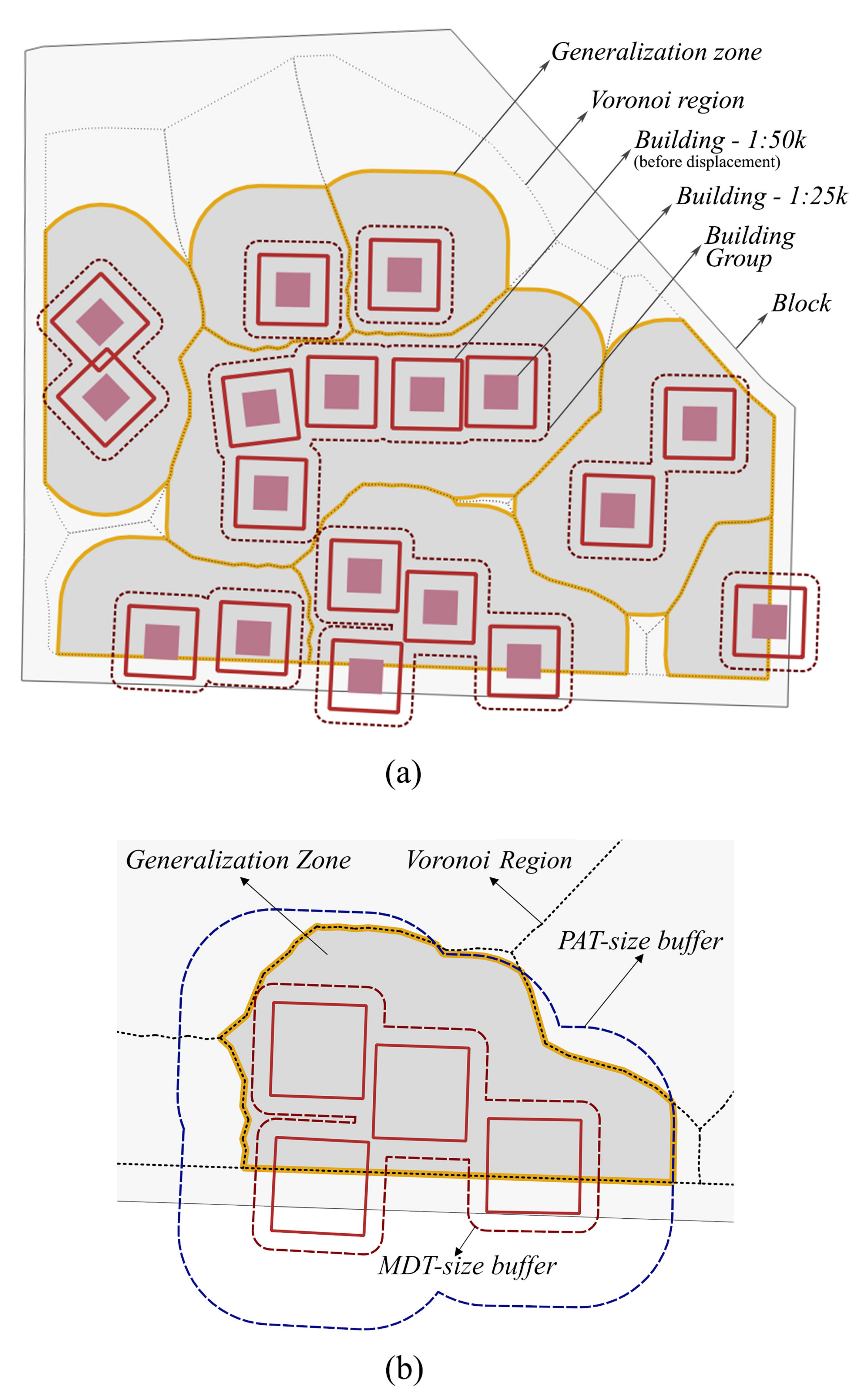
Figure 1. Map space allocation to the building groups in the blocks (adapted from [1]). (a) block, generalization zones and building groups, (b) generation of generalization zones.
Ijgi 10 00105 g001
Figure 2. The sizes of forward (1) and inward (2) buffers to detect the linear patterns in the case of perfectly aligned buildings.
Ijgi 10 00105 g002
Figure 3. Detection of the zones with linear patterns decided by the size of final polygon (light green). A linear pattern is (a) found, (b) not found.
Ijgi 10 00105 g003
Figure 4. Narrowed zones of linear (collinear and curvilinear) patterns. (a) The inward 20 m buffer of the PAT-size-dissolved buffer (yellow) and the included areas (hatched); (b) the narrowed zones (green).
Ijgi 10 00105 g004
Figure 5. Grid point set of a generalization zone.
Ijgi 10 00105 g005
Figure 6. Flow diagram of the displacement approach.
Ijgi 10 00105 g006
Figure 7. Buildings before (unfilled) and after (filled) toward-center displacement. The conflicts between buildings and roads: (a) reduced, (b) resolved.
Ijgi 10 00105 g007
Figure 8. Inward displacement.
Ijgi 10 00105 g008
Figure 9. Elements of grid point weight modification in the example of a building: (a) unique polygon of the main buffer ( U P o l y m b ), (b) unique polygon of the auxiliary buffer ( U P o l y a b ), (c) grid points colored by KDE-based initial weights and topologic conditions for their modifications.
Ijgi 10 00105 g009
Figure 10. An illustration of the inner displacement.
Ijgi 10 00105 g010
Figure 11. An illustration of the post-processing.
Ijgi 10 00105 g011
Figure 12. The corresponding triangles used for the quality evaluation.
Ijgi 10 00105 g012
Figure 13. An example of a group with three buildings and their triangles before and after displacement.
Ijgi 10 00105 g013
Figure 14. Azimuth difference.
Ijgi 10 00105 g014
Figure 15. Displacement quality rank statistics of generalization zones.
Ijgi 10 00105 g015
Figure 16. Boxplots of average zonal building displacement amounts ( μ d ) and zonal displacement amounts of building group centroids ( Δ d C ).
Ijgi 10 00105 g016
Figure 17. Boxplots of angle, length, and compactness comparison measures for all of the zones.
Ijgi 10 00105 g017
Figure 18. Boxplots of angle, length, and compactness comparison measures for all of the zones with linear patterns.
Ijgi 10 00105 g018
Publisher’s Note: MDPI stays neutral with regard to jurisdictional claims in published maps and institutional affiliations.