1. Introduction
The first anthropomorphic humanoid robot, WABOT-1, was built at Waseda University, Tokyo, as part of the WABOT project (1970). WABOT-1 was a full-scale humanoid robot, able to walk, grasp and transport small object with its hands, and equipped with a vision system used for basic navigation tasks. The same research group later built WABOT-2 (1984) and WABIAN (1997), both biped humanoid robots, and is still active in the field [
1].
Around 1986, Honda started to develop a biped platform that underwent through several stages, called “E” (1986–1993) and “P” (1993–1997) series, and led to the creation of ASIMO [
2]. ASIMO was officially unveiled in 2000 and had a significant impact on the media all around the world. It is a humanoid platform with an advanced vision and navigation system, able to interpret voice or gesture commands and to move autonomously with a semi-dynamic walking mode. In 2008, Aldebaran Robotics launched NAO, a programmable humanoid robot that is now the standard platform for several robotics competitions, such as the RoboCup Standard Platform League [
3,
4]. NAO has been the most widespread robot in academic and scientific usage, used to teach and develop advanced programming and control in educational and research institutes all around the world. In 2013, Boston Dynamics announced the Atlas robot, a biped robot capable of complex dynamic tasks, such as running, moving on snow, performing a backflip, balancing after being hit by projectiles or jumping on one leg [
5].
Several other humanoid structures have been designed both by academy and industry with a variety of solutions as platforms for research and applications for service (as for example in assistance to humans, entertainment, guide operations), exploration, human-robot interaction and learning. Some additional examples include: iCub [
6], and for research on learning; WALK-MAN, [
7], which is used as a rescue robot for unstructured environments; Pepper, [
8], which is used for investigations on human-robot interaction; Ami, [
9], which is designed for applications in Domotics; REEM-B, [
10], which is designed as service robot for general human assistance; ARMAR, [
11,
12], which is used as a collaborative robot in Domotics tasks. While there has been a huge development in the control of these robots, they all share a common body architecture, which has not evolved much during time. In fact, most of them are based on a serial kinematic chain with spherical-revolute-universal (SRU) joints for their limbs. This mechanical structure is fairly easy to manufacture and control, while offering a large workspace for its size.
However, serial architectures are outperformed by parallel mechanisms in accuracy, speed, stiffness and payload. Parallel manipulators, also named parallel kinematic machines (PKM), are closed-loop mechanisms that are characterized by high accuracy, rigidity and payload [
13]. A parallel manipulator is defined as a mechanical system that allow a rigid body, called from now on an end-effector, to move with respect to a fixed base by means of two or more independent kinematic chains. Very few research groups have proposed robotic limbs with a parallel architecture. As reported in [
14], the first robotic legs with parallel architecture were developed in Japan. The first one was the ParaWalker robot, developed at Tokyo Institute of Technology in 1992, while the Waseda Leg (WL) WL-15 was built in 2001 at the Takanishi laboratory of Waseda University, followed by the WL-16 and the WL-16R series from 2002 to 2007 [
15]. The last version of the Waseda Leg is the WL-16RV. The WL robots are biped walking chairs, whose legs are based on the architecture of the Gough platform. The WL design inspired other teams in designing novel biped robots built on parallel mechanisms, such as the Reconfigurable Quadruped/Biped Walking Robot of Yanshan University, which is built on four legs with three identical universal-prismatic-universal limbs (3UPU) each. The LARMbot [
16,
17,
18,
19,
20,
21] was designed as a low-cost, user-oriented leg for a service humanoid robot. Its leg is designed as a 3UPR PKM. Gao used similar lower-mobility parallel legs for a hexapod robot [
22,
23,
24]. The main drawback for most of these legs, however, is the small dimension of their workspace, which allows for a very small step size when compared to the human one [
25,
26,
27,
28].
In order to characterize the mechanical performance of robotic limbs that have been developed in the last few decades, the main parameters of representative humanoid robots are listed in
Table 1 [
27].
Each robot is classified according to its kinematic architecture (serial or parallel), system weight and height, maximum step size, maximum gait speed, degrees-of-freedom of each leg and year of production. As reported in
Table 1, most of the existing robots have 6-DoFs serial limb architectures. The most famous humanoid robots, such as ASIMO and NAO, are all based on this kinematic scheme. The size and weight of the robots did not change significantly with the years, and even the step size and speed are in a reduced range of values when compared to the size of the robot. Most of the advancements are in the performance of control and gait planning, while the mechanical design has not evolved. Furthermore, the payload capacity of the current structures of humanoid robots is rather small (for example, NAO can lift only 0.15 kg per arm), and they can be often operated with poor dynamics and stiffness. Therefore, challenging design issues can be still identified in improving or designing structures of humanoid robots and parallel mechanisms can be considered a solution or an alternative to achieve a mechanical design with better performance in accuracy, payload and dynamics, not only mimicking human capabilities.
2. Human Anatomy with Parallel Mechanisms
Humanoids are designed with structures and operations replicating human ones. Human nature has a complex design in structure composition, with several kinds of material and architectures that humanoid design can replicate only very partially. The most referenced part of human anatomy for humanoid robot structures is the skeleton system, which inspires solutions mainly with rigid links in serial kinematic chain architectures. However, considering that the functionality of human movable parts is mainly due to a combined/integrated structure of bones and muscles, the reference structure for humanoid robot design can be considered a parallel architecture that combines bones as rigid movable links and muscles as linear actuators.
Figure 1 summarizes such an understanding by looking at the bone skeleton structure (
Figure 1a) that, together with the muscle complex (
Figure 1b), can give a model of functioning mechanisms with parallel mechanisms (
Figure 1c). The antagonist functioning of muscles is characterized by the fact that the muscles mainly act with pulling actions when they are contracted, and therefore full mobility requires alternated actions of two muscles in pulling and releasing. For complex motions, such as 3D movements, a bone is actuated by a complex group of muscles that still control the operation through antagonist functionality.
Thus, although a basic principle can be still referred to the example in
Figure 1, human anatomy can be of difficult replication in efficient compact designs for humanoid robots. However, the inspiration from human anatomy for designs with parallel mechanisms can be summarized in solutions that are characterized by two platforms with relative motion, which are connected and actuated by a number of pairs of linear actuators working either independently (as rigid variable links) or in antagonism (as cable-driven links). A central rigid link, replicating the bone structure and functionality, can be included in the parallel mechanism design both to keep the size and the load capability.
In particular,
Figure 2 gives an example of such an inspiration from human anatomy, with a parallel architecture of bones and muscles for designing a movable arm with a parallel mechanism that is based on the antagonist actuation of a pair of muscles for a planar motion. As per the forearm motion in the sagittal arm plane due to the elbow articulation,
Figure 2 shows a solution with a central rigid link L that is connected the platforms with revolute joints whereas the actuation is given by two variable cable links l
1 and l
2. with revolute joints yet. As in
Figure 2b, l
2 shortens, simulating the contraction of the muscle, while l
1 is stretched for the release of the corresponding antagonist muscle.
Figure 3 shows an example of modelling of the complex structure of bones and muscles in a human trunk, in
Figure 3a, for designing a humanoid trunk, as in
Figure 3b, as based on parallel mechanisms with the above-mentioned design. In particular, the central rigid link L can be designed with a serial chain of links L
i replicating the vertebras, which are connected by spherical joints or 2-DOF revolute joints in a suitable number to ensure the required ranges of flexion and torsion. The complex of the muscles can be replicated with a suitable number of couples of antagonist variable cable links, such as l
1 and l
2, to give a required mobility to the shoulder upper platform with respect to the waist lower platform. The number of those couples of cable links can be limited to only four, and their actuation can be programmed to give some other motion capability when driven in a non-antagonist mode.
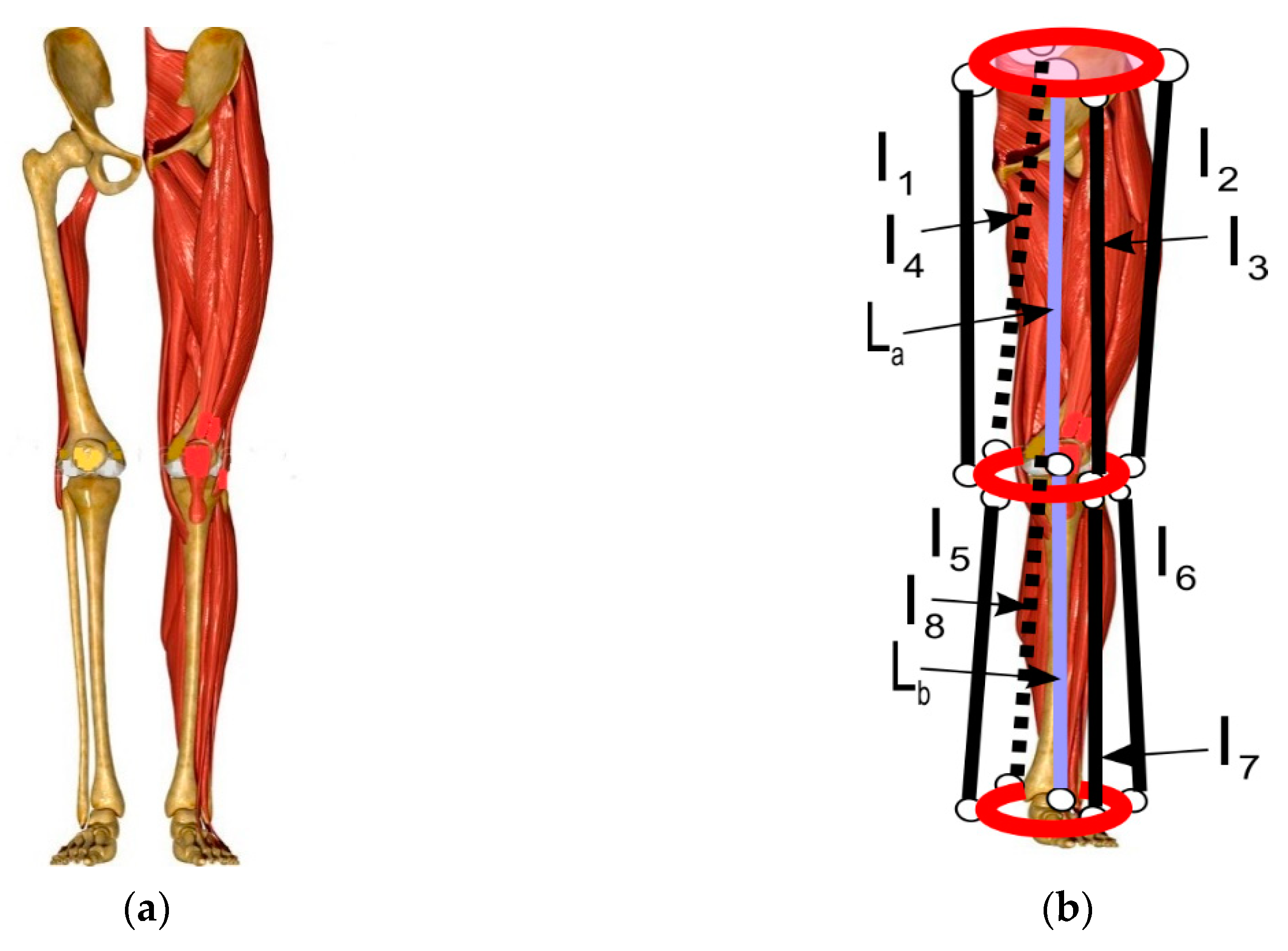
The leg structure in
Figure 4 can be aimed to the locomotor part of a humanoid robot, with a leg mobility with a large range of motion and a large payload capacity, due to the synergy of the action of the bones and muscle complex. This characteristic can be preserved by using the above-mentioned concept of having the bone load-supporting structure replicated by a central rigid link and the platform relative mobility ensured by the pulling action of the cables working. In addition, the human leg anatomy of the leg-shank structure can be preserved by conceiving two similar parallel mechanisms in series with the mobile platform of the upper-leg part as the fixed platform for the mobile shank platform. The mobility can be designed with a proper number of couples of antagonist cable links as per a required mobility. Thus, the upper-leg parallel mechanism can be designed to give 3 DOFs to the mobile knee platform with a central rigid link L
a and four cable links l
1, l
2, l
3, l
4, which can be activated to give planar motions in sagittal and traversal anatomical planes and even a torsion motion as per a hip joint mobility when the four cables are activated in cooperation (not in antagonism mode). Similarly, the shank motion can be limited to two cables l
5, l
6, for the sagittal motion of the end-effector ankle platform that is connected to the knee platform by a rigid link L
b. Additional cable links l
6, l
7 can be provided to provide the twist motion for the ankle platform.
The examples in
Figure 2,
Figure 3 and
Figure 4 give conceptual kinematic designs of the idea of using parallel cable-driven mechanisms for replicating the human anatomy made of bones and muscle complexes in a design of humanoid robots or parts of them.
Figure 4 is an example of a combination of parallel mechanisms for the leg structure and how they can be assembled in series.
3. Requirements and Performance for Humanoid Robots
Humanoid robots are aimed at replicating/mimicking human operations mainly in locomotion, manipulation and sensing for human-like tasks.
Figure 5 summarizes those main aspects that should be considered for design and operation in mimicking human nature and its functionality, making a humanoid solution efficient, durable and functional, with even better/different performance than those of humans.
In particular, locomotion requirements can be obtained by analyzing sizing issues and functionality features. Fundamental attention can be addressed to leg size for and as function of the required step size and vice versa. In addition, speed data can be a characteristic of the prescribed task and can affect the previous mentioned aspect. All together they can contribute to design leg workspace, in order to replicate the area of mobility of a human leg, which is usually characterized by suitable values of step length and step height. In addition, the locomotion can be performed in several modes just like humans, such as walking, running and jumping, with characteristic performance in terms of speed and motion smoothness. Among practical requirements, payload capability pays a fundamental role, not only in sustaining the weight of the full humanoid, but also considering the loads and actions that the leg locomotor will have to collaborate with. A locomotion system must be provided with control software and hardware, as well as motion strategies with proper path planning and leg coordination for balancing during bipedal operations.
Similarly, the design and functionality of manipulation system of a humanoid robot can be guided by requirements in terms of sizes and operation performance. Once the size is defined, the constraints for the arm workspace and mobility can be defined to include each point that the arm can reach and all the configurations in which that point can be reached (with different orientations for different manipulation tasks). Accuracy and dexterity are characteristics that can be dictated by the task but also by the flexibility in operation that can be expected by the use of the robot humanoid, The payload of the arm structure should be enough to support a variety of human-like manipulation tasks, which can be linked with a good accuracy and repeatability. Manipulation capability should also be characterized in terms of dexterity, as expressed by multiple reachable arm configurations with suitable motion and dynamics characteristics. Motion planning is also a practical aspect, coming from synergy with the control design and motion programming, with issues that can be determinant in the design and functionality. Finally, the extremity of an arm, such as a hand or grasping systems, needs to be considered as part of the problems for a well-integrated solution in manipulations, including grasp actions.
Sensing in humanoid robots can be considered as being integrated with the capabilities in locomotion and manipulation, as well as additional features, which are nonetheless based on the biomechanics of the structure and their operation, so that sensor equipment is needed with characteristics and composition, as outlined in
Figure 5, for the main human-like operation. Those sensors can be useful for the motion and action of a humanoid at proper levels of performance, as well as for monitoring and supervision purposes. Inertial measurement units (IMUs) are useful to have a feedback on the human-like motion, in order to react to external forces or unbalanced configurations with a proper balancing motion. Important sensing is also related to force detection, both in manipulation and locomotion, with or without further control feedbacks. Sensors are significant in grasping tasks that require tactile capability. Image recognition is a sense that makes a humanoid aware of the environment and cameras are needed for autonomous navigation through obstacle detection, and for area inspection through object recognition. Other common sensors in humanoid robots are haptic sensors to perceive the interaction of a humanoid robot with the environment. In addition, a humanoid robot should be equipped with sensors that are sources of information for the task under execution.
Referring to an average human characterization,
Table 2 lists an example of numerical evaluation of design requirements for humanoid design, as referred to in the requirements in
Figure 5, as linked to solutions with parallel mechanisms.
The expected performance in
Table 2 is estimated considering design solutions with parallel architectures, enhancing the whole humanoid design with minimum–maximum ranges that can satisfy task characteristics and/or performance operation in other aspects.
Design solutions with proper dimensions and range of motion can be defined by using computations for the corresponding model and formulation of the kinematics and force transmission of parallel manipulators. In particular, referring to the antagonistic operation mode in the conceptual scheme in
Figure 6a, the kinematics of the operation can be formulated with loop-closure equations as
where the design parameters are the position of the spherical or revolute joints
Ai,
Aj,
Bi and
Bj, and the length of the central link
L, as well as the motion parameters given by parallel limb lengths
li and
lj. Given the antagonistic functioning of the system, a single equation for each antagonistic pair of actuators is enough to fully characterize the kinematics of the pair, and the length of the remaining limb can be obtained as a function of its antagonist.
A static or dynamic model can be used to evaluate the actuation forces in the linear actuators or equivalent cable-driven structures, and the equilibrium to translation can be given by
where the equilibrium to rotation can be expressed as
where
Fi and
Fj are the actuation forces in the
i-th and
j-th limb respectively,
R is the reaction in the central link and
P and
M represent external forces and moments applied to the lower platform, as shown in
Figure 6b.
The above formulation can be further elaborated for specific cases, as shown in the LARMbot example in
Section 4, which is controlled with kinematic and static models that are developed from Equations (1)–(3), as outlined with details in [
17].
4. An Illustrative Example
A direct experience of the authors in using parallel mechanisms in humanoid designs refers to LARMbot design. The LARMbot humanoid robot has been developed in the last decade with contribution of several researchers at LARM laboratory of University of Cassino and South Latium, [
29,
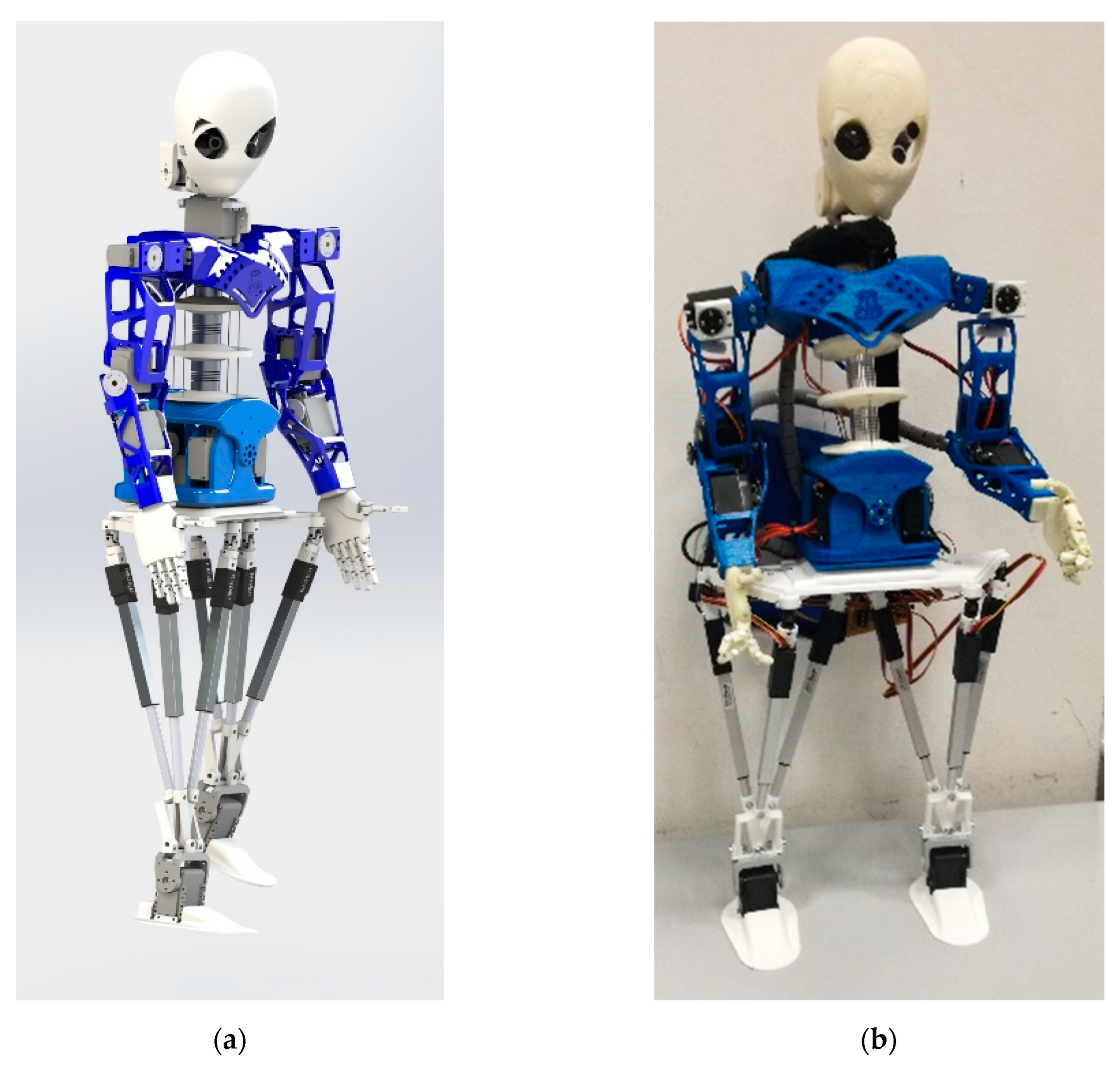
30]. The LARMbot design, shown in
Figure 7, is a service robot for autonomous walking and manipulation tasks, with basic performance in mimicking structure but functionality of humans. As pointed out in [
16,
29], a first full prototype of LARMbot was assembled in 2015, while a second version, LARMbot II, with a different leg architecture [
16,
17] is now available for lab testing at LARM2 in University of Rome “Tor Vergata”.
The LARMbot design is characterized by two main parallel mechanism systems, namely one for leg-locomotion and one for arm-trunk. The prototype has been built by using commercial components available off-the-shelf and by manufacturing other parts with 3D printing, in order to get a system that is 850 mm tall with a weight less than 3.70 kg. Its payload capability is 0.85 kg for manipulation, and more than 3 kg for the torso/leg operation, whose parallel architectures give a structure that is considerably stronger than traditional humanoids. The payload to weight ratio is 0.23 for manipulation and 0.81 for weightlifting, which is considerably larger than in other existing humanoid robots. For example, the similar-sized NAO humanoid, which is designed with serial kinematic architectures, has a payload to weight ratio of only 0.03 [
3,
4]. Furthermore, LARMbot is energy-efficient, with a peak 20 W power consumption in LARMbot II prototype, as tested in [
17].
The trunk design in
Figure 8a is based on the CAUTO solution, [
18], as an underactuated cable-driven serial-parallel mechanism whose kinematic scheme is shown in
Figure 8b as referring to the conceptual design in
Figure 3. The LARMbot trunk is composed of parallel mechanisms with four cables and a central underactuated serial chain whose extremity joints are fixed in the center of the mobile shoulder plate of the parallel mechanism. It is a 4SPS-(3S) parallel mechanism with 4 DOFs, which are actuated by the four motors for varying the length of each cable. The mechanism is inspired by the human torso bone-muscle complex as in the scheme in
Figure 3b, with a serial-kinematic compliant spine in the center as a 3S chain, shown in
Figure 8b. The cables act as antagonist muscles for motion control in coordination of the cable pairs, according to the kinematic model in Equation (1), with
L representing the spine structure. In addition to its main function of load-supporting structure, the LARMbot trunk can be used with its controlled motion to enhance and support walking balance too, as outlined in [
17].
The leg-locomotor design is shown in
Figure 9, with the conceptual design schemes of two legs with human anatomy inspiration, whereas its operational characteristics are presented in [
19]. The design is inspired by the human upper-leg structure as in
Figure 9a, which refers to a single parallel mechanism in
Figure 4, as per gross functionality. Three actuators represent the main muscle groups of the upper leg, namely hamstrings, quadriceps and adductors. Each leg is designed as a 3UPR lower-mobility parallel mechanism, which is shown in
Figure 9b as connecting the hip in the waist platform to the ankle mobile platform. It is actuated by three linear actuators in the links, which converge to a single point of the ankle platform. A special joint design ensures the point convergence of the three linear actuators, resulting in a workspace larger than similar parallel manipulators, as well as human-like mobility, which is also characterized by no singular configurations, as discussed in [
20,
21]. With reference to
Figure 6 and
Figure 9b, the kinematics of each leg can be expressed as
where
Ai represents the position of the spherical joints on the upper platform,
A0 is the center of the upper platform,
B0 is the point of convergence of the three limbs and the motion parameters are given by linear actuator lengths
li. This formulation can be obtained from Equation (1) by imposing the convergence of the limbs and removing the fixed-length central limb, and it can be used to control the motion of the locomotion system of the robot, as explained with details in [
19,
20,
21].
4.1. Experimental Validation
Laboratory tests have been worked out to check the feasibility of the proposed design and to characterize the performance of the LARMbot prototype during its development. In particular, in this paper, experiences of lab testing are reported for motion analysis of the LARMbot leg—locomotor as a parallel biped.
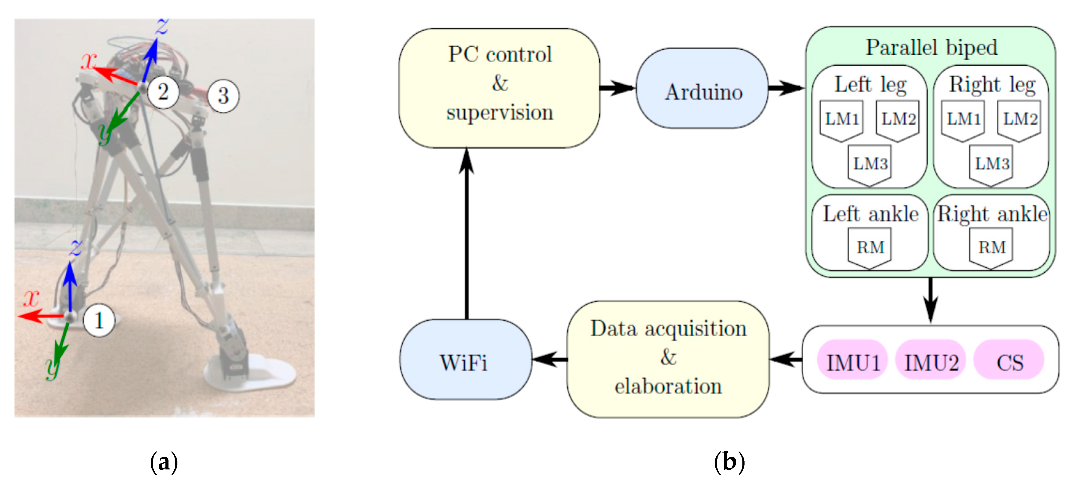
Figure 10 shows the structure of the tested LARMbot biped locomotor and a conceptual scheme for the control and test acquisition of biped walking. In
Figure 10a, the location of the three sensors that are used for the acquisitions is shown, as well as the orientation of the two IMU (inertial measurement unit) sensors (1) and (2). In
Figure 10b, a conceptual scheme is presented for the overall testing frame and connections. The first IMU, denoted as (1), is attached to the left foot, and the second IMU, denoted as (2), is placed on the hip platform. A current sensor (CS) is denoted as (3), and it is fixed on the hip platform where also the rest of the electronic components is installed. The control system is based on an Arduino Mega board to command the eight leg motors, where six of them are linear actuators, and two are rotational motors to drive the ankle joint of each leg. IMU (1) is attached to the left foot to characterize the walking operation cycle’s motion in terms of angular velocities and linear acceleration; IMU (2) is used to characterize the hip platform motion; and the current sensor is used to measure the power consumption during walking. An ESP8266-based board is used to acquire and elaborate data from sensors. The information is sent wirelessly to a PC to store data by using Wi-Fi.
The walking cycle was defined by programming the motion of the biped from point to point. Five different points are stored, which include the corresponding positions of the linear actuators and the rotations of the ankle motors. The first point describes the statically balanced position at the beginning and end of each motion cycle, while the other four points define the main poses of the robot during each step cycle. Thus, the gait is computed by deriving the intermediate positions of the legs through a zero-moment-point approach. Four snapshots of a walking operation test are shown in
Figure 11, where the locomotor can be observed while moving from a right-forward double support phase to a right swing, passing through left swing and left-forward double support phase. In this motion, the three linear actuators of each leg contract and extend with a behavior that corresponds to the muscles of the human upper leg, as discussed previously.
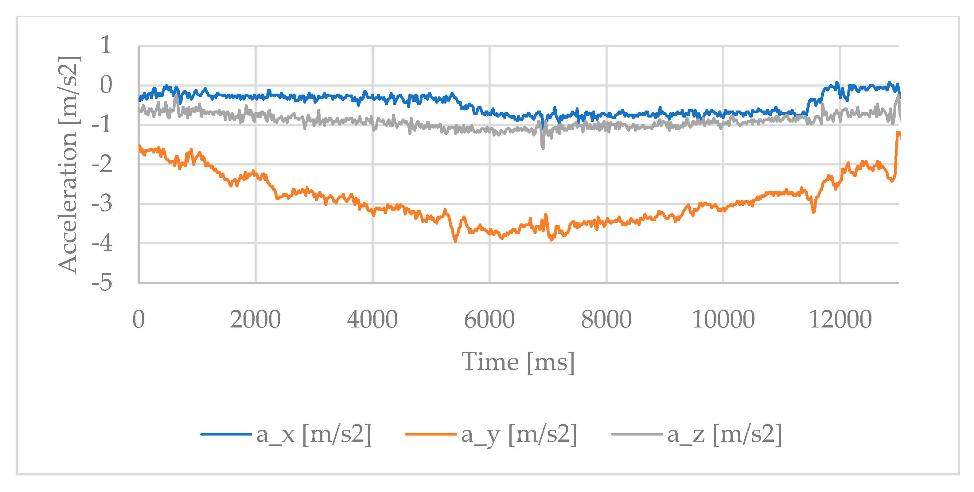
The acceleration of the hip during this motion has been acquired by IMU (2) and it is reported in
Figure 12. The main motion takes place along the
x-axis on the horizontal pavement surface and can be observed in the continuous periodic behavior in the graph, which corresponds to the back-and-forth motion of the hip during human-like walking. The y component of the acceleration is instead associated to the lateral balancing motion of the hip, while the acceleration along the
z-axis is negligible as referring to vertical displacements during a smooth walking.
The acquisition data of IMU (1) are shown in
Figure 13 and illustrate the behavior of the foot during the experimented walking gait. The main component is again in the x direction, with negative peaks corresponding to the foot’s dorsiflexion. When the foot is on the ground, the acceleration is negligible, as expected, although some vibration and slipping can be still observed in the data plot. The acquired data for the walking gait test in
Figure 12 and
Figure 13 show a smooth motion, with acceleration values that are always smaller than 1.5 m/s
2 in absolute value.
Another significant characteristic of the LARMbot humanoid is its low power consumption. An estimation of the power consumption during the walking gait in
Figure 11 can be obtained by the current sensor (3) acquisition together with the power supply voltage (7.4 V), and the results are reported in
Figure 14. The static power draw is less than 4.00 W, with a peak of 8.09 W and an RMS (root main square) value is of 5.82 W during the walking operation. Large values of acceleration, up to 4.0 m/s
2 in absolute value, can be observed instead in the squatting weight-lifting test that was reported in [
17], with a 1.00 kg payload and results in
Figure 15. The higher value is required by a needed faster balancing action, but the motion is still smooth, and the peak value is well within human-like motion. This acquisition refers to a test of squatting motion with a payload on the arms of the prototype, to show the feasibility and convenience of the parallel mechanisms in LARMbot prototype in a typical high-load task, with the leg design working in coordination with the trunk for balancing. The squatting motion consisted in a vertical up-down displacement of 40 mm at a speed of 10 mm/s, which was obtained by an up-down displacement in the parallel legs that has been properly balanced by the trunk motion with only a pitch adjustment, as shown in
Figure 16.
Summarizing the design peculiarities and the laboratory experiences, the parallel mechanisms with human anatomy inspiration in the LARMbot design provide a significant high performance in payload and energy efficiency, as well as the required motion capability for basic humanoid operations.
4.2. Comparison with Serial Architectures
In order to outline the advantages of parallel mechanisms over serial architectures, a comparison between the LARMbot humanoid and the successful NAO design is here reported. The data for LARMbot is obtained either from the experiments presented in
Section 4 or from previous works [
17,
31], whereas the technical specifications of the NAO humanoid can be found on the website of its manufacturer, Aldebaran Robotics [
32]. The performance values of both LARMbot and NAO are summarized in
Table 3, with reference to the requirements of
Table 2.
Even though NAO is able to maintain a faster step rate than the LARMbot, it is outperformed by the latter in payload and efficiency. The parallel architectures of the LARMbot enable a much higher payload and payload to weight ratio, while still maintaining a lightweight design. Usually, serial architectures are preferred to parallel ones for their improved workspace and reach. However, in this case, thanks to its properly designed human-inspired parallel mechanisms, the LARMbot design shows a good performance, not only in payload and energy consumption, but also in workspace, mobility and speed, which can be considered comparable to human ones. The main drawback of parallel design is given by singular configurations and increased control complexity (e.g., kinematics that cannot be solved in closed form or with multiple solutions, force closure for cable-driven mechanisms).
A comparison with NAO only is here reported, since it has a similar size of LARMbot and comparable characteristics. Some other examples may include the iCub [
5] and ASIMO [
2] platforms that are of a different (larger) size. In general, it can be concluded that parallel mechanisms with antagonist functioning give improved mechanical performance of the humanoid operation in terms of accuracy, stiffness, payload and efficiency, at the not particularly high expense of control complexity.


