Article

Displacement Analysis and Design of a (2–RRU)–URR Parallel Mechanism Performing 2R1T Output Motion for Thumb Rehabilitation

Mechanical Engineering, Tokyo Institute of Technology, 2-12-1 Ookayama, Meguro-ku, Tokyo 152-8552, Japan
*
Author to whom correspondence should be addressed.
Robotics 2020, 9(3), 67; https://doi.org/10.3390/robotics9030067
Submission received: 29 June 2020 / Revised: 7 August 2020 / Accepted: 26 August 2020 / Published: 28 August 2020
(This article belongs to the Special Issue Theory and Practice on Robotics and Mechatronics)

Abstract

:
The thumb assists other fingers, and any damage in its functionality prevents the human hand from performing dexterous functions. In this paper, the kinematic design of the (2–RRU)–URR parallel mechanism as the application of the thumb rehabilitation device is proposed. This mechanism is an over-constrained mechanism capable of achieving the required mobility with fewer joints. Three degrees of freedom exist—two rotational and one translational mobility—that are related to each thumb movement: adduction–abduction and flexion–extension. Considering the narrow space of the hand, actuators are designed to divide its placement into the surface of the palm. To avoid the collisions between the device and the hand, an offset was adopted. The displacement analysis problem is solved by dividing it into two parts: the planar motion generator (PMG) and orientation generator (OG), according to each functional motion, and the corresponding equations and procedures are presented. To clarify the basic characteristics of this mechanism, the reachable workspace of the PMG and rotational ability and sensitivity of the OG is demonstrated numerically. Because a large input torque difference is dangerous in the rehabilitation mechanism, the effective workspace is determined according to the magnitude of the input torque differences and compared with the measured thumb movements.

1. Introduction

The human hand is a very effective organ, and it significantly affects human dexterity in daily life. In particular, the role of the thumb is to support the other fingers during grasping and picking-up movements [1]. Because these movements provide manual dexterity skills to humans, the loss of the thumb function severely hinders daily activities. Therefore, thumb rehabilitation is important to help patients recover their thumb function and restore hand functionality. Rehabilitation is a type of therapy aiming to recuperate the patients’ movement functions. In conventional rehabilitation therapy, a rehabilitation therapist stands near the patient, and they always care for their patient in all rehabilitation therapy processes manually. Since rehabilitation therapy requires keeping a higher force continuously than the stiffness of paralyzing, young therapists are needed. The effect of the rehabilitation depends on various factors such as the timing of the therapy, the intensity of the therapy, the number of the therapist, the attention of the therapist, the number of repetitions, the cooperativeness of the patients, and so on [2,3,4]. Thus, the lack of the amount of the therapist issue is a critical issue due to it affects the recovery of the patients’ motor function. However, because the population is aging, the number of therapists and patients is disproportionate, and each therapists’ burden is increasing rapidly [5]. Even if the therapists’ capacity fully prepares for each patient, the therapy time is limited and short (only 5.2% of daytime in two weeks take the care from the therapist [6]). As one of the solutions to these issues, the rehabilitation robot is proposed. Relatively than the therapist, the robot not only can provide the given constant force continuously but also can provide the same moving trajectory consistently. This advantage solves the number of therapists and has a positive effect on increasing the number of repetitions. Repetition training helps recover the patients’ motor function after the intensive rehabilitation process. It induces the plasticity of the brain for the stroke patient and helps to keeps its activation [7]. Furthermore, this training also is used as a warm-up process before the primary therapies.
In previous works of literature, there were two main types of rehabilitation robots: end-effector and exoskeleton type [8,9]. An end-effector type interacts with the patients’ movement by a single attachment part on the distal end of the latter’s body [10]. These types of robots are designed to externally locate its main parts to the patients’ body. Moreover, its end-effector was designed to attach with the distal end of the users’ body. Due to this characteristic of the design, this robot controls only the position and the orientation of the end-effector. Furthermore, those mechanisms have the advantage of a simple structure and easy adaptation to different sizes of the human body even though the robot cannot control each joint angle of limbs or fingers. Figure 1 shows the three conceptual drawings of the end-effector mechanism. In this figure, the first type is the end-effector type that uses serial linkages, in which each joint is actuated, as shown in (a) [11]. Second Figure 1b [12,13] shows the case where closed-loop mechanism is used and (c) [14] shows the case where cables are used.
An exoskeleton-type mechanism independently provides the required angle and force to each joint through the various attachment. The axis position of each joint is determined when it is attached to the human. If the patients’ joint axes are not aligned with the robots’ joints, then a mechanical singularity of the total system composed of the robot and human occurs [15]. In addition, a hybrid-type robot, which is the intermediate structure of two types, was reported [8]. For example, one of the mechanism parts is designed as an exoskeleton and attached to the human body. It is connected to another part like the end-effector type. In another case, the base of the mechanism is attached to the patients’ body like an exoskeleton, but the structure of the mechanism is of the end-effector type.
In the case of the exoskeleton, the distance between the link and human bone caused by the muscle and skin becomes the cause of the misalignment when human joints move. In other words, even though kinematic joints are precisely aligned with human joints in the home position, the axes of the kinematic joints cannot respond to the changes in the human joint axis during performance. Figure 2 shows the situation of the misalignment. Anatomically, the position of the human joint axis changes when the limbs move. In particular, multi-degree of freedom (DOF) joints have different characteristics according to bone shape. Figure 3 shows the explanation of each joint and bone of thumb and index finger. The first joint of the thumb, the thumb carpometacarpal (CMC) joint, is a saddle joint and can be categorized as a 2-DOF joint. However, when each axis of rotation rotates, an additional sliding motion occurs along each axis, which causes the joint axis to move [1]. These anatomical features make it difficult to perform the required movement using the mechanical joints, and there is a possibility of misalignment. This limitation remains a challenging point in the field of rehabilitation robots.
To solve this limitation, various types of design were reported. Figure 4 shows the linkage structures of previous studies. First, the redundant linkage structure was reported [15,16]. This structure makes the rotational center of the joint align by giving additional mobility than required mobility. For example, one mobility is needed in the proximal interphalangeal (PIP) joint of the index finger, but this type of mechanism was designed for its joint mobility to be two. The additional mobility is constrained by the overall constraint condition to include hand when the mechanism is attached to the hand. In this paper, the constraint condition means that the physical constraint of the mechanism given by the placement of the mechanisms’ joints. The remote center of rotation structure was designed to comply with the rotational center using the mechanical closed-loop linkage, slider, and so on [17,18,19,20]. However, those two types: the redundant linkage structure and the remote center of rotation structure; are structurally very complex, and bulky. Furthermore, those structures were designed so that their mechanism is attached to fix the center points of each finger node as shown in Figure 4 a,b. On the side of the paralyzed hand, since this hands are hard to perform the extension of their hands but easy to show the opposite movement (like grasping motion), those designs are inconvenient to be equipped on the patient’s hand without additional steps such as the botulinum toxin (Botox) injection for loosening patient’s muscle softly. Furthermore, we have not found any adaptation cases to be used on the CMC joint. Even if those designs are adapted to CMC joint, we predict that those structures are not easily designed to provide all mobility of CMC joint. On the other hand, the serial linkage structure has been proposed [21,22,23]. This structure was the design such that the end-effector of the mechanism is attached to the distal point of the finger. As the advantage of this structure, the distal movement of the finger is focused on when designing the mechanism, and it is relatively easy to equip to the hands compared to other structures. For this reason, this structure can adapt to providing the mobility CMC joint.
Due to the complex structure of the CMC joint, most exoskeletal robots had been designed in their previous study to actuate the flexion–extension movements without the thumb. Only a few robots of the previous research have been actively designed to control the thumb. For example, the isolated orthosis proposition for thumb actuation (IOTA) was reported in [24]. This mechanism had 2-DOF, and it was designed two actuated joints that can actuate the CMC joint and MP joint. This mechanism was reported the maximum efficiency of 44%. However, the author restricts the CMC motion only to permit the palmar abduction-adduction movement. Leonardis et al. reported electromyography(EMG) controlled robotic hand exoskeleton system [25]. This mechanism has 2 DOFs with adaptable function to the hand size. One actuator of this robot was connected to the four fingers (index, middle, ring, and little fingers), and another actuator was used for the thumb movement. Regarding the thumb function, only the flexion–extension movement was considered and designed. An exoskeleton device called a “five-fingered assertive hand” was studied. It achieved the five finger motions using three driving parts, actuated by a tendon-driven system [26]. Regarding the thumb-driving part, it had two actuated joints. One of the actuated joints controlled the MP joint and the IP joint at the same time. Another actuated joint controlled the CMC joint for flexion–extension movement. Another previous device named “Rutgers Master II-ND” was reported their thumb approach using one pneumatic actuator [27]. This actuator is connected to the tip of the thumb from the base located in the palm. Through this actuator, the device controls the flexion–extension movement. The two passive universal joints are connected between actuator to fingertip part and actuator to base. Thanks to these joints, this mechanism allows the adduction– abduction movement. The thumb exoskeleton reported by Lambercy, et al. [28] is designed their thumb part to allow the flexion–extension movement by a passive hinge joint and to control the abduction-adduction through the linear actuator. Furthermore, a passive universal joint connected between the CMC part and MP part allows for adaptation to the center of the CMC joint. Moreover, this mechanism manufactured by a 3D printer of less than 150 g was realized. Wang et al. proposed an actuated thumb exoskeleton for hand rehabilitation named ATX [29]. This mechanism was designed its actuated DOF as five to control the total DOF of thumb finger independently. Two of the total DOF were used for the CMC joint, and those were controlled by two actuators to perform each movement: flexion–extension and adduction–abduction. Agarwal et al. have proposed the exoskeleton robot for thumb rehabilitation [30]. This mechanism has four DOF, and it designed their CMC chain that consists of the four revolute joint and one prismatic joint. This chain becomes to 4-bar linkage by the constraint between hand and chain when the mechanism attached to the hand. This phenomenon allows its DOFs two from five. To control two DOFs, two actuators were used for controlling each thumb movement.
To sum up, the design of previous studies can be categorized into three cases. The first case [24,25,26] is the mechanism design, which focused and controlled only one movement, and other movements were physically limited. However, it is not enough to adequately preforms all thumb movement through the one actuator. Notably, it may hard to respond according to the big size of the object when presented with the grasping motion. The second design [27,28] controlled only one of all movements as the same as the first design, but it allows the other movements through the passive joints. Thus, the different movements passively moved through the human hand. However, the paralyzed of the patients’ hands generally moves to the inside of the palm. On the other way, it is hard to moves outside due to their contraction of the muscle. Thus, we are not sure the passive joint is enough to give the other movements for the rehabilitation. The third case [29,30] of the mechanical design controls all movements of the CMC joint through two actuators. Each actuator corresponds to one actuator for each movement. This type of mechanism has 2 DOF when the device attached by the constraint with the human hand. However, it is questionable whether it can deal with the additional sliding motion due to the CMC joints’ saddle structure, as mentioned above. Based on this discussion, controlling all DOF of the CMC joint, and solving the misalignment issue of CMC joint are still existed as the challenge points.
To solve these limitations, our research team proposed an exoskeleton-type parallel mechanism for thumb rehabilitation using a (2–RRU)–URR parallel mechanism. For its structural characteristics, the axes of all adjacent joints are orthogonal, and all links form a circular arc [31]. Furthermore, the proposed mechanism is an over-constrained mechanism that can be designed using the minimum number of joints required to provide the necessary degrees of freedom. In addition, this proposed mechanism achieves a compound motion that consists of a rotational and translational motion, which differs from the motion of famous parallel robots such as the Stewart-Gough platform, DELTA, and Agile eye [32,33,34]. The parallel robot with the presented compound motion has the possibility of various applications, but it is usually not famously applied in the field that most parallel robots used. In a previous study, Liu, X. J., and Wang, J., reported a spatial parallel robot with two rotational motions and one translational motion [35,36]. This robot has three nonidentical kinematic chains that are connect its base to the output link, and it is actuated by three prismatic actuators. To compare with the aforementioned proposed robot, this robot seems similar from a functional point of view. However, there are differences in the presented motion, actuator type, and structural characteristics.
In our previous report [31], we discussed only the basic kinematics such as displacement and sensitivity analysis of the proposed mechanism without the consideration of its application. In this paper, we extended the previous paper to a kinematic design of the proposed mechanism taking into account the application for thumb rehabilitation device. Then, this paper includes workspace analysis with the comparison of the human measurement data, improvement of the kinematic structure by introducing an offset of the link in order to avoid the collision between the human hand and the device and enable the easy locations of actuators on the hand, and actuation torque characteristics evaluation for safety. Thanks to the improvements based on the theoretical analysis, it is expected that the development of a useful thumb rehabilitation device has been enabled. The fabrication of the prototype and experiments will be reported in our next paper.

2. (2-RRU)-URR Mechanism and Its Mobility

2.1. Mechanism Configuration

The components of the (2-RRU)-URR mechanism are the base frame, output link, two RRU chains, and one URR chain [31], as shown in Figure 5. Moreover, the symbol of the round bracket means that dividing the chains from another chain and the chains. This mechanism was designed so that its output link can be attached to the center point of the metacarpal (MP) bones to assist and reinforce the required movements of the MP and CMC joints. Figure 6 shows the required movements of the thumb: flexion–extension and abduction-adduction. When the coordinate system is defined as shown in the figure, the flexion–extension movement of the measured point moves in the y z plane and it consists of the translation along the y axis and the rotation around the x axis. In the observation of the thumb movement, the displacement of the z axis caused by the two mobility mentioned above is measured as the small range (1∼3 mm by the motion capture measuring). To simplify the required mobility for design, assuming that the small range can be negligible. For this reason, the flexion–extension movement is related to the displacement of the translation along the y axis. Furthermore, since the orientation of the MP bone still exists; and rotation around the x axis at the measured point (relative rotational mobility) is required. On the other hand, the abduction-adduction consists of rotation around the z axis and translation along the y axis. Both mobilities mentioned above are related to the movement from the CMC joints, and the relative mobility is related to the MP joint. In summary, this mechanism is proposed for a rehabilitation device to perform the motions of the thumb, as shown in Figure 6.
Based on these ideas, the concept of the mechanism was designed as shown in Figure 7. In this figure, the hand is in the middle of the base frame of the mechanism. Thus, joints in the base frame are in the palm, at the back of the hand, and near the wrist. With respect to the thumb movement, the chain, which is located near the surface of the thumb, may collide with the wrist or the thumb. Furthermore, because the hand has a limited narrow space to set the joints and the actuators in practice, an offset that creates distance between the joints for evading collisions was adopted. Figure 5 shows a diagram of the proposed offset-adapted mechanism. In this figure, the offset is the link in the x-axis direction between joints G and H. Owing to the offset, the fixed-point position of joint O was changed from near the wrist to the palm.
For convenience, we denote the chains ACE, BDF, and GHIJ as chains 1, 2, and 3, respectively. Chains 1 and 2 are in the x y plane, and have the same kinematic structure in which four R joints are arranged from the base to the output link. Three successive R joints are parallel, and the fourth joint is perpendicular to the others so that the third and fourth joints form a universal (U) joint. In addition, chains 1 and 2 are arranged so that they are parallel to each other. This means that the six revolute joints s A , s C , s E and s B , s D , s F are parallel, and the two fourth-revolute joints s E 2 and s F 2 are coaxial. Chain 3 is perpendicular to the x y plane and is composed of four R joints. The second-to-fourth joints are parallel, and the first joint is perpendicular to the others, forming a U joint with the second one.

2.2. Mobility Analysis

To verify the mobility of the proposed mechanism, Grueblers’ mobility formula is applied. Its result shows that the DOF is calculated as zero as follows:
6 ( L J 1 ) + i = 1 J f i = 6 ( 8 9 1 ) + ( 1 × 8 ) + ( 2 × 2 ) = 0
where J, L, and f i are the number of joints, number of links, and DOF of the joints, respectively. However, this calculation result is different when compared to the real behavior from the observed mobility of the prototype. In this observation, three DOFs existed in the proposed mechanism: rotational motion around the z axis, translational motion in the HP direction, and rotational motion around the x axis. To consider the actual DOF of this mechanism, the constraints imposed on the output link by each chain have been accounted for. First, the constraint with respect to the coordinate system P x y z is considered according to the structural and observed features of this mechanism. According to the kinematic structure of chain 1, its constrained mobilities are the rotational motion of the output link around the y axis and the translational motion at P in the z axis. The same constraint conditions are imposed by chain 2. In the case of chain 3, the rotational motion around the y axis and translational motion at O in the x axis are constrained. These constraint conditions are also confirmed from the constraint wrenches of the proposed mechanism ( S c ). The constraint wrench is the 6 × 1 vector, which is shown the constraint condition of the output by the structure of each kinematic chain. The number of constraint wrenches is related to the DOF of each chain. This wrench should be satisfied with the orthogonal condition with all joint screws in each kinematic chain [37]. Those wrenches of each chain are described as follows:
S c i , 1 = 0 0 1 0 0 0 , S c i , 2 = 0 0 0 0 1 0 ( i = 1 , 2 ) , S c 3 , 1 = 1 0 0 0 0 r , S c 3 , 2 = 0 0 0 0 1 0
where r is the distance between O and P. In the case of the proposed mechanism, the six constraint wrenches are derived as shown in Equation (2). Hence, because each chain has 4 DOFs, there are two constraint wrenches with respect to each chain. In Equation (2), S c i , j refers to the constraint imposed by the ith chains, where j = 1 , 2 . From Equation (2), three of them are independent, and the others have the same values as those of one of three independent wrenches. Then, the three independent constraint wrenches ( S c ) are obtained as
S c 1 = 0 0 1 0 0 0 , S c 2 = 0 0 0 0 1 0 , S c 3 = 1 0 0 0 0 r
These wrenches indicate that the output link can perform the rotational motion around the x axis, rotational motion around the z axis, and translational motion along the y axis. In summary, the proposed mechanism is a 2R1T mechanism, where R and T are the rotational and translational outputs, respectively. It has been confirmed that this mechanism facilitates the same motion as that by the previous mechanism even though an offset was applied.

2.3. Overall Jacobian Matrix

To understand the relationship between the input and output velocity of the proposed mechanism, the overall Jacobian matrix of the lower-mobility parallel mechanism is derived using the screw theory [37]. Considering the actuated wrenches ( S a ), one actuation wrench is derived for each chain. The constraint wrenches and the actuation wrenches are respectively classified as the force and moment components as follows:
S c n = s c n , f s c n , m , S a i = s a i , f s a i , m ( n = 1 , 2 , 3 )
where the symbols of f and m in the wrenches respectively represent the components of the force and the moment. Based on S c i and S a n , the overall Jacobian of the proposed mechanism is described as follows:
J T = J a J c = s a 1 , m ( S a 1 S A ) s a 1 , f ( S a 1 S A ) s a 2 , m ( S a 2 S B ) s a 2 , f ( S a 2 S B ) s a 3 , m ( S a 3 S H ) s a 3 , f ( S a 3 S H ) s c 1 , m s c 1 , f s c 2 , m s c 2 , f s c 3 , m s c 3 , f
where J c , J a , and J T are the constraint, actuation, and overall Jacobian matrices, respectively. Furthermore, S A , S B , and S H are the joint screws of the actuation joints. In the six dimensions, the relationship between the input velocity θ ˙ a and output velocity V = [ ω T v T ] T with the constraint equation is described using the overall Jacobian matrix as follows:
θ ˙ a T 0 3 T T = J T ω T v T T
where θ ˙ a and 0 3 are the velocity of the actuation joints θ ˙ a = [ θ ˙ A , θ ˙ B , θ ˙ H ] T and a three-dimensional zero vector, respectively.

3. Displacement Analysis

The displacement analysis is that geometrical relationship between actuated joints and the output link without regard to the force/torques that cause the movement is formulated and analyzed. To derive the kinematic equations of the proposed mechanism, the mechanism is divided into two parts: planar motion generator (PMG) and orientation generator (OG). Then, equations for those parts are separately derived. Please note that unlike the previous study of [31], this study introduced the offset.

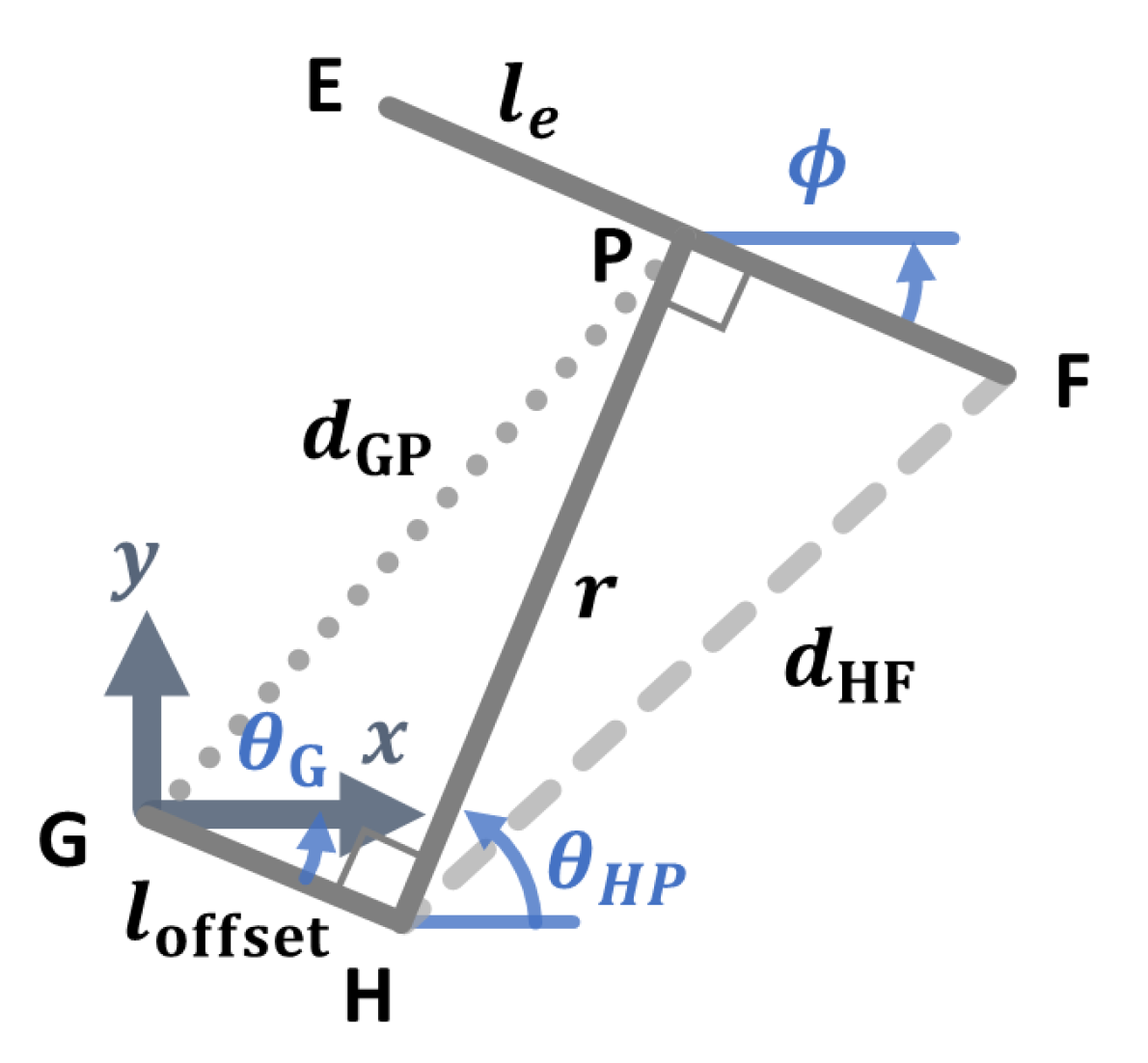
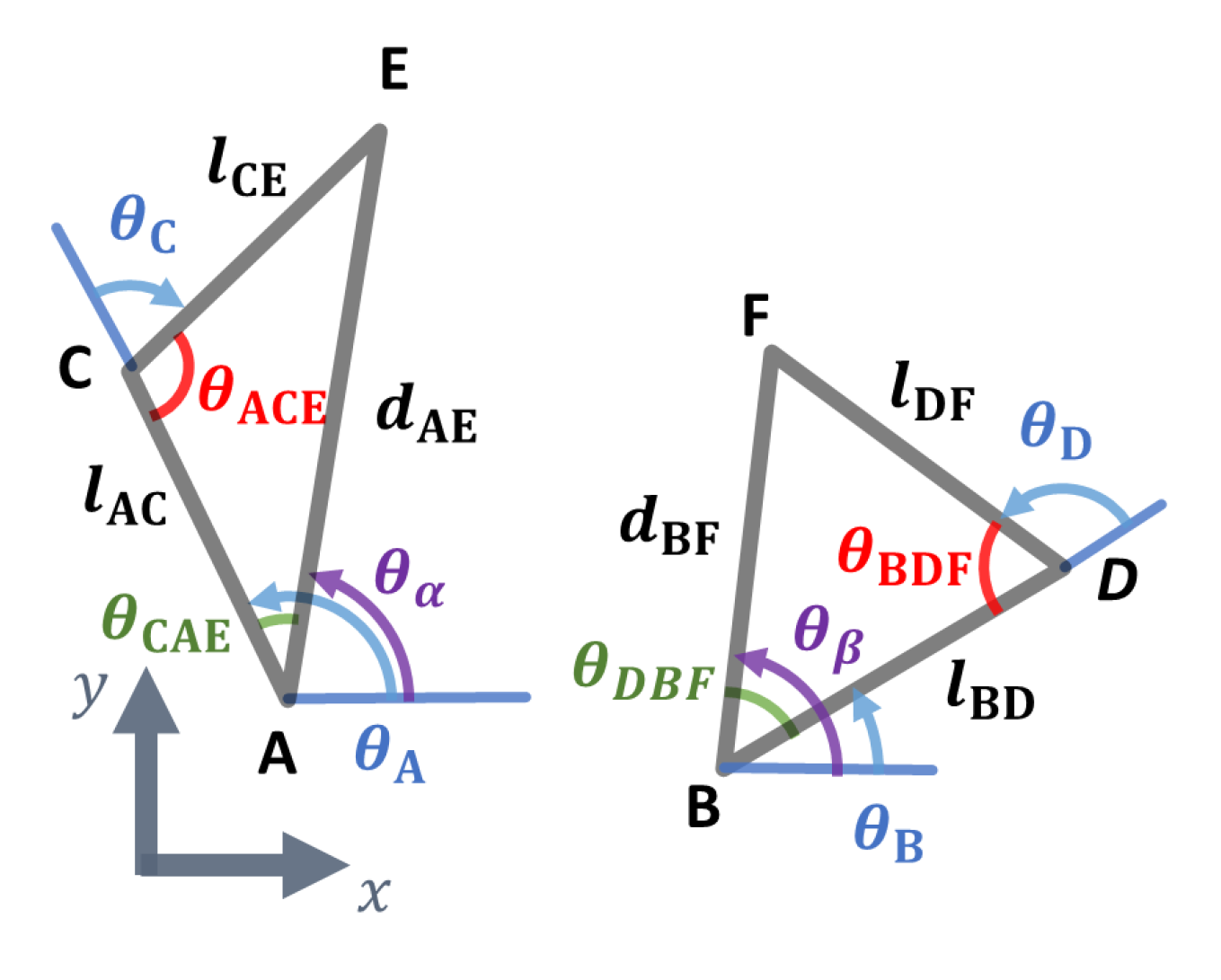
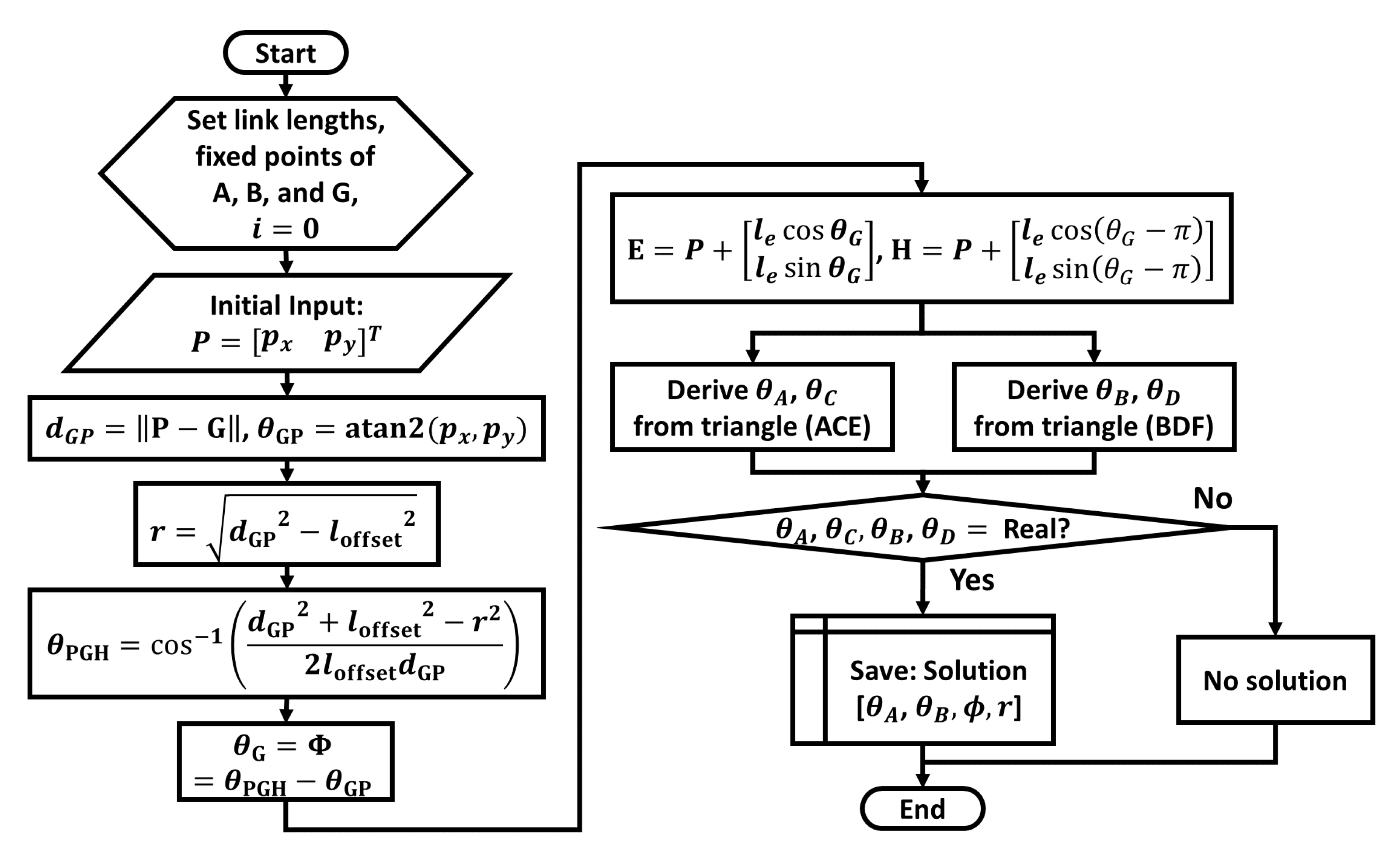
3.1. Forward Displacement Analysis of Planar Motion Generator

The PMG is shown in Figure 8. This diagram shows the top view of the x y plane. Part GHP is the projection of the kinematic chain GHIJ on the plane of linkage ACEFDB. If the connection and constraint of link r are not included, then the PMG can be considered to be a planar six-bar linkage. In general, planar six-bar linkages with a single closed-loop require three actuators. Because there are only two actuators at joints A and B, this condition cannot be used to solve the forward displacement analysis of the six-bar linkage of ACEFDB. If one of the joints C or D is assumed as an actuated joint and the angles of θ A and θ B are given, then the end-effector point of the six-bar linkage can be calculated using the four-bar linkage method mentioned in [31]. However, according to the constraint given by the chain GHP (details are described in the following sub-section, its value should be adjusted. At this time, the calculation is ongoing with the assumption of joint C as the temporal actuation joint.
Figure 9 shows the procedure of the forward displacement analysis of the PMG when joint C was considered to be the temporal actuation joint. As shown in this figure, the pre-allocation of the constant parameters, such as the length of the links and fixed points of the base joints, is defined before the calculation. In detail, all the kinematic parameters are classified as l, θ , and d, which represent the link length, joint angle, and distance between two joints, respectively. As mentioned above, when θ A and θ B are given, the positions of joints C and D are fixed, and other chains such as CDFE can be considered to be a four-bar linkage. Based on this, when θ C is given, the orientation angle Φ and position vector of point P are derived via the general method of the four-bar linkage. Because link EF, r, and link GH are perpendicularly constrained to each other, link EF and link GH are always in parallel, and this is described as Φ = θ G . Figure 10 shows the constraint condition of the GHP. Therefore, r can be derived considering the right-angled triangle condition of r, d G P , and l offset . Furthermore, θ EPH , which is the angle between link EF and r, is derived using the cosine laws, and it should be 90 with respect to the constraint condition. In this process, θ EPH is calculated for each θ C value, and these are confirmed to satisfy the above constraint condition. The tolerances of θ EPH are 90 ± 0.25 . The overall forward displacement of the proposed mechanism can be derived when θ A and θ B are arbitrarily given.

3.2. Inverse Kinematics of Planar Motion Generator

Before calculating the forward kinematic analysis of the PMG, the constraint condition of the proposed mechanism is considered. As mentioned in Section 2, chain 3 and link EF are perpendicularly connected to each other. In the case of PMG, chain 3 is represented as the link r and link GH (offset link). As the constraint condition of PMG, link GH and r, and link EF and r, are always perpendicularly connected. Therefore, the relationship between the orientation of link EF ( Φ e ) and the angle of joint G ( θ G ) is θ G = Φ , i.e., Φ is passively determined by θ G , and θ G is perpendicularly determined in the direction of the link r. There are two output components of the PMG: r and Φ . Because these are related to the position of point P, if we know the position vectors of p x and p y , then the output components of r and Φ can be derived to be the opposite. Actually, the trajectory of the real thumb movement is recorded by the measurement system using the position vector of the x axis and the position vector of the y axis. Considering the comparison results or tracking with the real movement, for convenience, the input components of inverse displacement analysis are determined to be p x and p y . If l GH and the position of point P ( P = [ p x , p y ] T ) are given, then d GP and r are derived by considering the right-angle condition of l GH , d GP , and r as follows:
d GP = P G , r = d GP 2 l offset 2
θ PGH = cos 1 l GP 2 + l offset 2 r 2 2 l offset l GP , θ GP = atan 2 ( p y , p x )
θ G = Φ = θ PGH θ GP
where d GP , θ PGH , θ GP , and θ G are the distance between joints G and P in the x y plane, angle of PGH, orientation angle of GP from the x axis, and joint angle of G, respectively. From the perpendicular conditions such as those of link r and FP, and link r and GH, the positions of joints H, E, and F can be calculated using Equation (9) as follows:
E = P + e x e y = p x p y + l e cos θ G l e sin θ G , F = P + f x f y = p x p y + l e cos ( θ G π ) l e sin ( θ G π )
Using the results of the positions of E and F as mentioned above, the angles of the joints of each chain are calculated using the cosine law. Figure 11 shows the triangle of chains ACE and BDF. If the case of chain ACE is considered, the detailed equations used to determine the angle of joints A and C can be described as follows:
θ CAE = cos 1 l AC 2 + d AE 2 l CE 2 2 l AC d AE , θ ACE = cos 1 l AC 2 + l CE 2 d AE 2 2 l AC d CE
d AE = E A , θ α = atan 2 ( e y a y , e x a x )
θ A = θ α + θ CAE , θ C = θ ACE π
where l AC , d AE , l CE , θ α , θ A , θ C , θ CAE , and θ ACE are the link length of AC, distance between joints A and E, link length of CE, orientation angles of AE from the x axis, angle of joint A, angle of joint C, angle of CAE, and angle of ACE, respectively. Because chains ACE and BDF have the same kinematic structures, each joint angle of chain BDF can be derived using the same method. Figure 12 shows the procedure of the inverse displacement analysis of the PMG.
In the results of the displacement analysis, there are four types of solution, as shown in Figure 13. Each solution is classified by the angle values of θ C and θ D . Considering rehabilitation, the users’ hands will be located inside the chain ACEBDF. To prevent collisions with the hands, solution (a) is considered suitable for the application in this study.

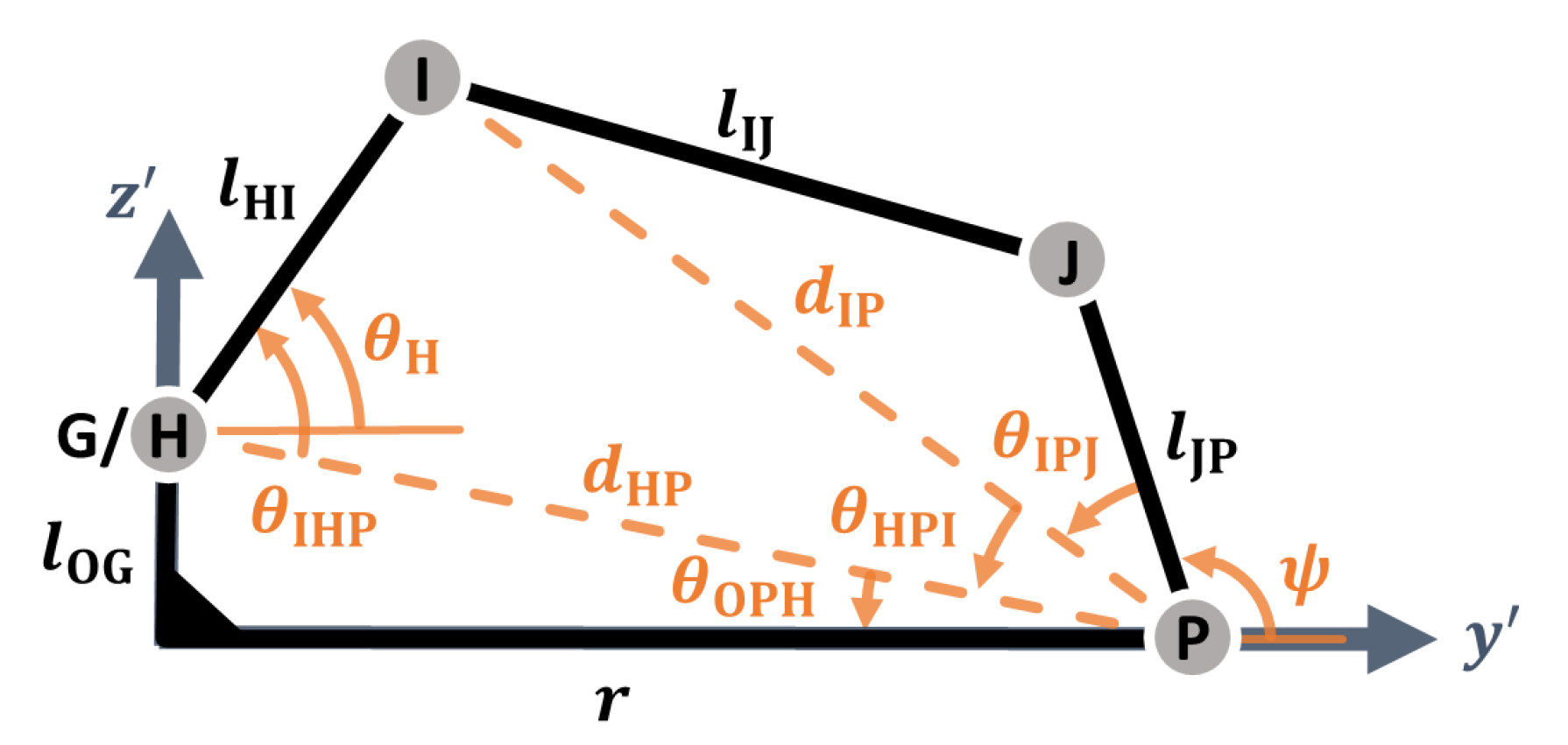
3.3. Forward and Inverse Kinematics of Orientation Generator

If the OG is projected on the y z plane of the P - x y z coordinate system, it can be considered to be a four-bar linkage even though an offset was adopted in the proposed mechanism. Figure 14 shows a diagram of the OG in the plane. The model of the OG can be considered to be a four-bar linkage. Because joints G and H overlap in the same position of the y z plane, and the rotational mobility of joint G does not affect the other links of the OG on this plane, these joints are considered to be a single joint. Because the link length r is calculated from the PMG, it is considered to be a known value. With respect to the forward displacement analysis, θ H is given as the input angle. Based on these, θ OPH , θ HPI , θ IPJ , and ϕ are derived. These symbols indicate the angle between r and link HP, angle between link HP and link IP, angle between link IP and link JP, and the orientation angle of link JP from the y axis, respectively. The equations are summarized as follows:
d HP = P H , d IP = P I , θ OPH = atan 2 ( r , l OG ) , θ H = θ IHP θ OPH
θ H P I = cos 1 d HP 2 + d IP 2 l HI 2 2 d HP d IP , θ I P J = cos 1 d IP 2 + l KP 2 l IJ 2 2 d IP l KP
Ψ = π ( θ IPJ + θ HPI ) θ OPH 0 θ IHP π π ( θ IPJ θ HPI ) θ OPH π θ IHP 0
With respect to the inverse displacement analysis, because the method mentioned above can be adapted if the input value changes from θ H to ϕ , then the output angle of θ H can be derived.

4. Kinematic Performance Analysis

To evaluate the performance of the proposed mechanism, the reachable workspace of PMG, range of the orientation, Jacobian matrix, and the effective workspace of the proposed mechanism are analyzed using numerical examples. In this study, the effective workspace is defined as the reachable workspace with a suitable actuation torque under the maximum force of the human hand. Kinematic parameters used in the analysis are listed in Table 1.

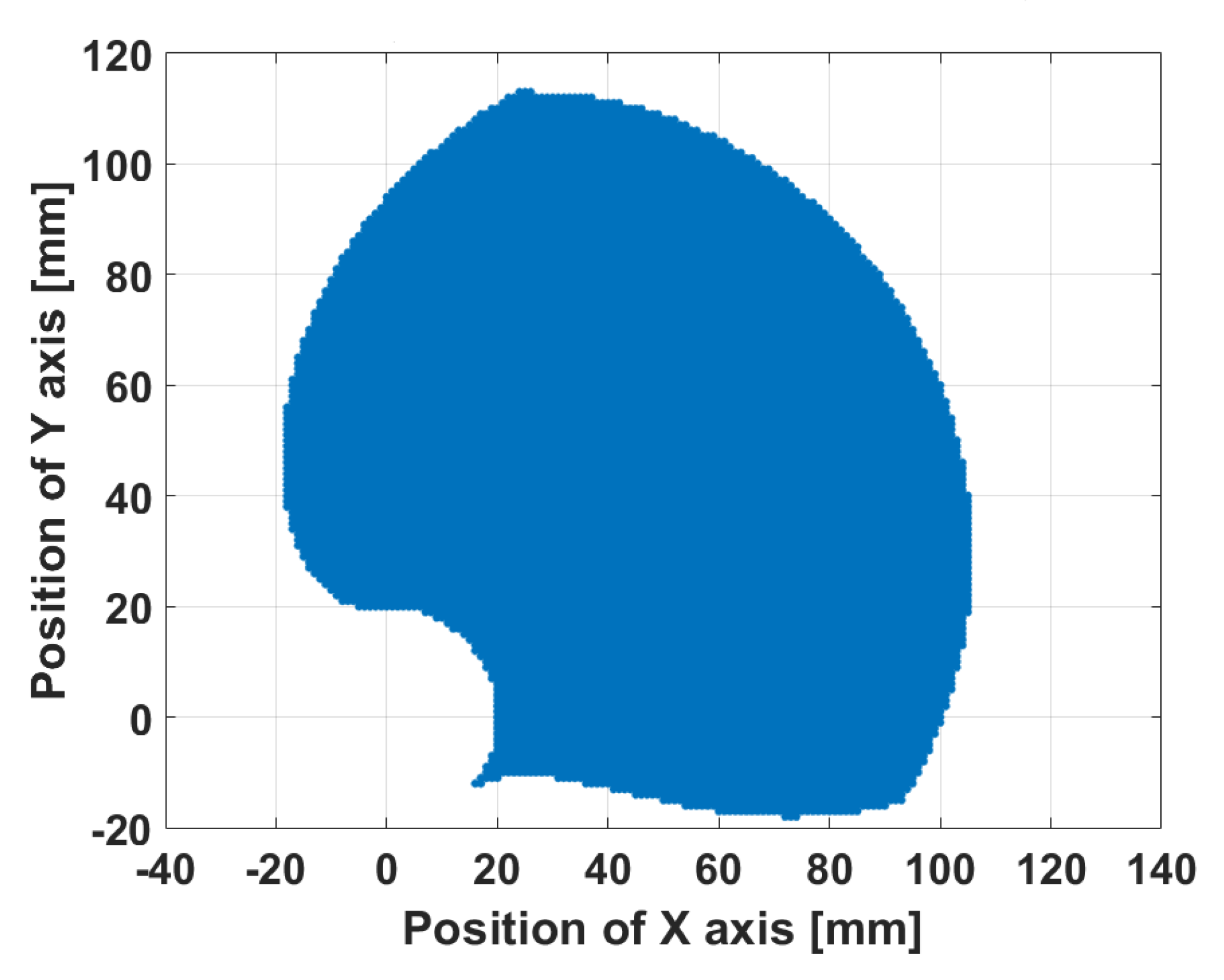
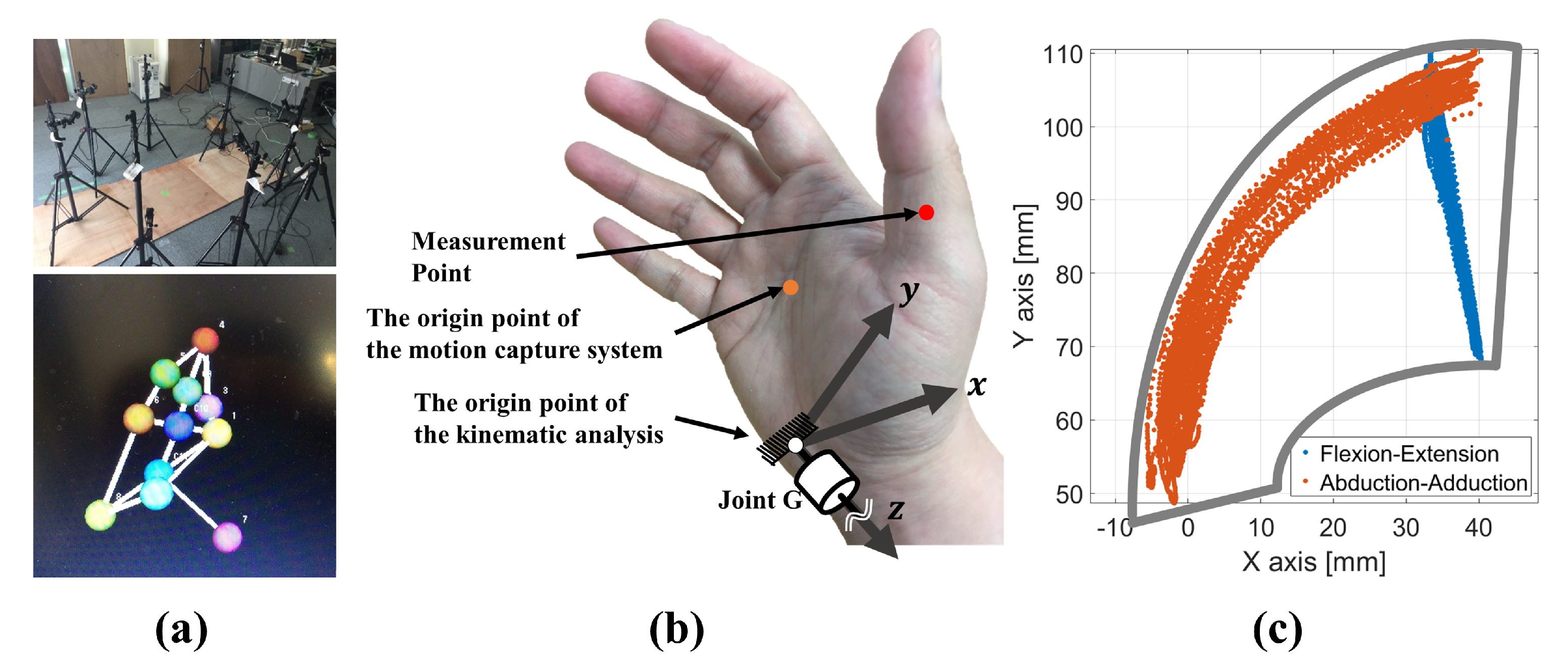
4.1. Reachable Workspace of Planar Motion Generator

The reachable workspace of the proposed mechanism is obtained in the x y plane caused by its constraint conditions. To obtain the reachable workspace, the method of inverse kinematic analysis is used. At this time, point Ps’ position, such as p x or p y , is given randomly, as listed in Table 2.
The reachable workspace was represented by the points where all the equations are as mentioned in Section 3. Figure 15 shows the obtained reachable workspace. Because the connecting structure between link EF and PH is perpendicular as mentioned above, the shape of the expected workspace is circular around the origin O. Owing to an asymmetrical placement between joints A and B, the reachable workspace is unequally distributed. The shape of the workspace is deformed owing to the constraint effect by the chains 1 and 2. Furthermore, the empty circular space around the origin is caused by the offset.

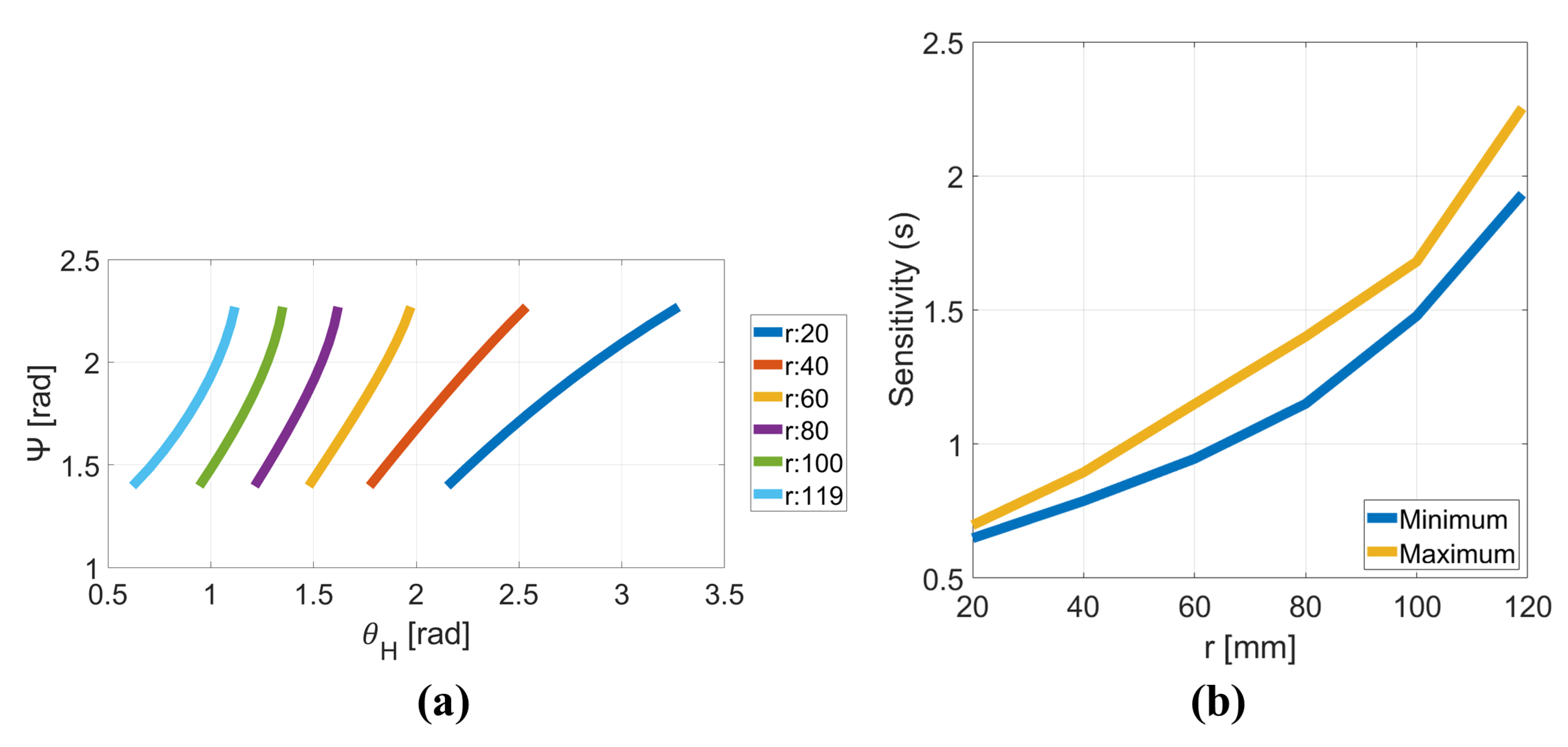
4.2. Rotational Capability and Sensitivity of Orientation Generator

To evaluate the rotational performance of the OG, the rotational capability and sensitivity were analyzed. The rotational capability is defined as the relationship between θ H and Ψ , and the sensitivity is the rate between them. In the calculation, the results are classified by each case of the r value, and the range of minimum and maximum values were determined from the results of the reachable workspace calculation as 0 mm to 119 mm. Considering the thumb rehabilitation, the minimum value of r was redefined as 20 mm.
According to the concept of this mechanism, the OG presents and supports the orientation angle of the MP bone of the thumb, and link JP is designed to be attached to that bone. According to the kinesiology of the thumb movement, the thumb has 50 as the range of angles during the adduction–abduction movement [38,39]. Assuming that the thumb is located at 0 in the natural posture of the hand, the range is 10 to 40 , and is related to Ψ . Considering the model of the OG, because the thumb CMC joint is located near joint J, the target range of Ψ is determined as 80 to 120 . Based on this, the rotational capability and sensitivity are derived. Then, the displacement results of the OG are selected, where the condition of the period of the target orientation when inputs θ H are randomly given in 0 360 , is satisfied. Therefore, the sensitivity is derived using the following equation:
s = Δ Ψ Δ θ H
where s is the sensitivity. Figure 16a,b show the results of the relationship between Ψ and θ H and the sensitivity in proportion to r.
In Figure 16a, there are six results, where r is kept constant at a certain value shown. The length of each result indicates the range of the orientating performance. Considering the target orientation, the ranges of the input angles vary for each r. These results are used to determine the range of the input angle as it adapts to different hand sizes.
Furthermore, Figure 16b shows the maximum and minimum values of the sensitivity for each length of r. In this figure, the sensitivities of each case are stable because there is no unnaturally rapid change between the maximum and minimum values as the signal of the singularity, but the difference between them increases when r increases. This result can be used for the optimum design of the proposed mechanism by predicting the singularity and understanding changes in the output angle with respect to the input angle.

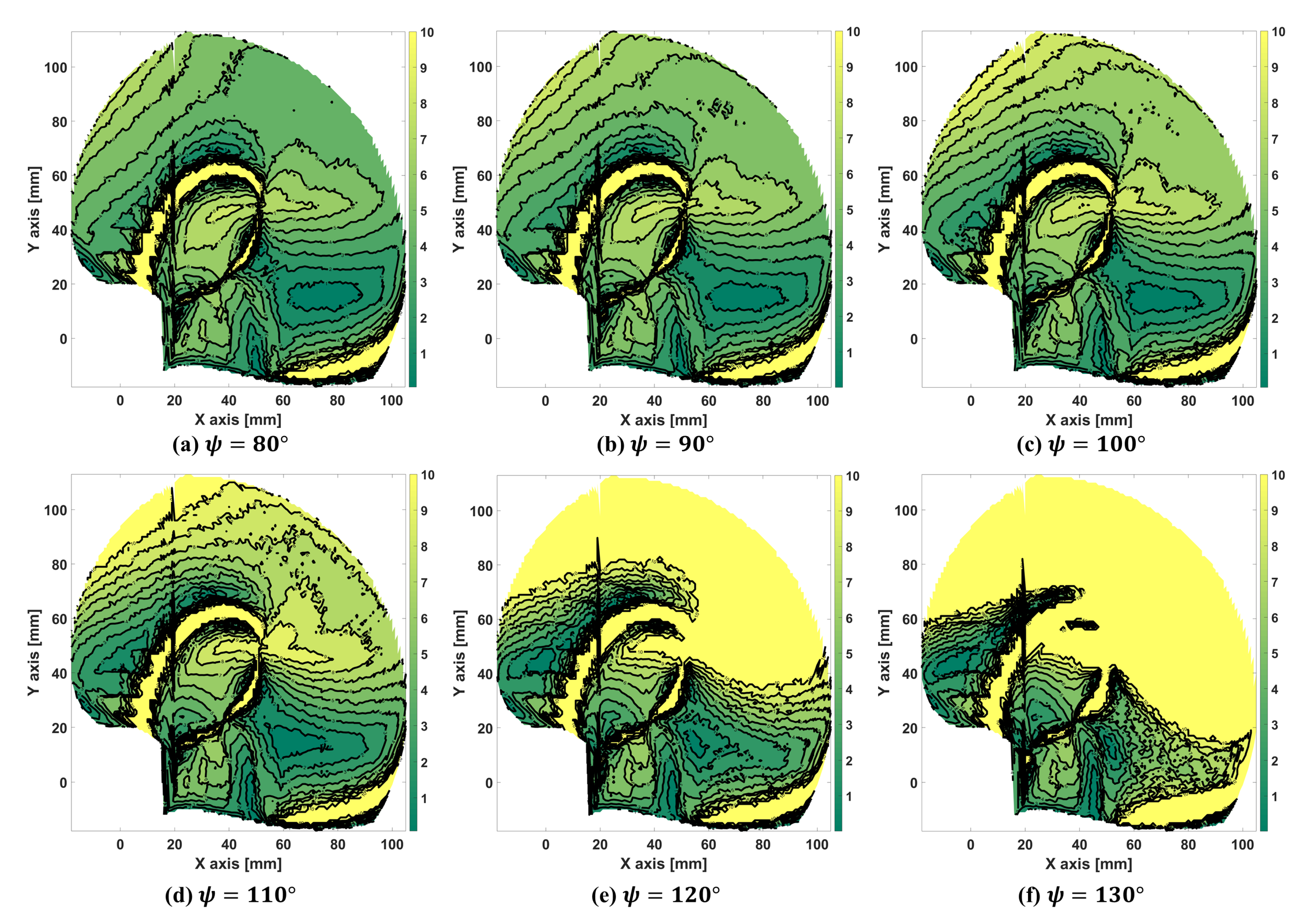
4.3. Effective Workspace with the Torque Difference

To design the proposed mechanism for safety, an effective workspace is defined and determined using the difference in input torques. This workspace indicates the sub-workspace of the proposed mechanism, where the rehabilitation device cannot damage the human hand. To define the effective workspace, we considered the difference between the maximum torque and the minimum torque of actuated joints. Before defining the effective workspace, static torque analysis is described as follows. When the external load (F) is applied to the output link, the relationship between the external load, actuation torque τ a , and constraint moment τ c is represented by the following equation using the overall Jacobian J T defined in Equation (5) based on the principle of virtual works.
F = J a T J c T τ = J T T τ , where τ = τ a T τ c T T , F = F f F m = F f x F f y F f z F m x F m y F m z T
where τ a = [ τ a 1 , τ a 2 , τ a 3 ] T = [ τ A , τ B , τ H ] T , τ c = [ τ c 1 , τ c 2 , τ c 3 ] T , f, and m are the actuation forces, the constraint forces, forces of external loads, and moments of the external loads. By solving Equation (18) with respect to τ a , input torques are obtained. The constraint force τ c does not directly correspond to the constraint force exerted on each chain because the Jacobian ( J T ) was derived based on the independent constraint wrenches, as mentioned in Section 2. Here, we focused only on the input torques in the numerical example to take the safety into consideration. We considered a case where the actuators run out and the input torques are out of control. In such a situation, the calculation result shows the case where one of the input torques is unusually higher than other input torques. Furthermore, another case, which is derived from a large torque compared with the maximum force of the human hand, is derived even in normal cases. We assumed that this case is a nonideal situation for the design, and it is expected that there is the potential for damage to the thumb owing to overload. The simple way of determining these cases is to make a comparison between one of the largest input torques and the smallest input torque. Therefore, the following value is proposed as an index to evaluate the safety of the rehabilitation device.
D = τ a , m a x τ a , m i n
where τ a , m a x and τ a , m i n are respectively the maximum and minimum values of the three components of τ a under a predetermined external load. The predetermined external load is determined as follows. Before determining the external loads, the requirement of the proposed mechanism for rehabilitation was decided. In the literature, the study of the botulinum toxin injection effect regarding the grasping force is reported. In this study, they reported that the injection is used for the reduction of the stiffness and it makes the patient feel only slight resistance to their distal of the hand [40]. Regarding the providing external force/torque to the patient during the rehabilitation therapy, the safety range of the force was reported as 0∼800 g [41]. Furthermore, the maximum torque able to apply to the patients’ CMC joint is 0.328 N [42] and the maximum force being able to apply to the patient is 45 N [43]. In the literature of kinesiology, the maximum torque of the CMC joint is approximately 6 Nm and the vertical element of that is 3 Nm [1,44]. Furthermore, there is the opinion that providing force over 5 N may not be suitable for patients with paralyzed hands [14]. Based on these backgrounds, we decided the requirements as follows:
  • The target user is expected as the paralyzed patient who got the botulinum toxin injection.
  • The maximum torque of the proposed mechanism is 6 Nm.
  • The target workspace is set as the same workspace of the healthy persons’ one.
As mentioned above, the vertical element of the maximum torque is 3 Nm, the maximum torque of the adduction–abduction movement direction is assumed as 3 Nm. Furthermore, the length of the thumb bone from the CMC joint to the MP joint is assumed to be 36.9 mm [45]. Because the output link is attached to the center points of the MP bone, the given force of the load ( f y ) is determined as the following equation: 3 × 0.0369 = 0.1107 N. Moreover, the moments of the load ( m x and m z ) are 6 Nm each. Thus, the given loads are determined as: F = [ 0 , 0.1107 , 0 , 6 , 0 , 6 ] T . Based on the magnitude of the index d, the effective workspace is categorized by the following condition:
  • If the magnitude of D is equal to or less than a threshold, the point is considered to be inside the effective workspace. In the following example, we used 6 Nm as the threshold value.
The effective workspace maps are shown in Figure 17 for each fixed orientation angle Ψ from 80 to 130 with increments of 10 . To better understand the characteristics of the mechanism, the workspace is colored according to the value of d: the area of d 10 is colored green, while that of D > 10 is yellow. From these figures, we know that the orientation angle significantly impacts the effective workspace. In particular, the yellow area increases with the increase of Ψ , and it is clearly exposed in the maps of 120 and 130 .
To determine the suitability of the proposed mechanism in thumb rehabilitation, the reachable workspace of the proposed mechanism and the finger trajectory measured experimentally, were compared. In the experiments, thumb trajectories were measured by a motion capture system, as shown in Figure 18a,b, where (a) and (b) show the environments of the measurement system and the points for measurement, respectively. The red, yellow, and white dots indicate the measurement point, origin of the motion capture system, and origin of the kinematic analysis in Figure 18b, respectively. Because there was some distance between the origins of measurement and kinematic analysis, a modification was made to unify the coordinate system with point O as the unified origin point. Figure 18c shows all the trajectories obtained during the movement of the center point of the thumb metacarpal bone projected on the x y plane. The red trajectory represents the thumb abduction–adduction movement, and the blue trajectory represents the flexion-–extension movement. Based on this figure, the boundary of the required workspace can be determined as the gray lines in the figure. Furthermore, Figure 19 shows the measured orientation angles in the flexion–extension movement along the z axis. Each wave indicates a cycle of movement. From the measurement data, the maximum and minimum angles varied from 29 to 2.5 .
Figure 20 shows the relationship between the effective workspace (green area) and the required workspace obtained for each orientation angle Ψ . From the results, it is known that the target areas overlap in the green area of the maps in cases (a) to (d). However, the yellow areas expose the target areas in cases (e) to (f). Therefore, it can be concluded that the proposed mechanism can provide thumb rehabilitation movements for an orientation angle Ψ ranging from 80 to 110 deg, while for further movements, an improved design is needed. Please note that the effective workspace decreases when the orientation angle of the OG is close to 130 . These results appear to be similar to the sensitivity results of the OG. Thus, the effective workspace is affected by the orientation angles of the OG. In particular, its workspace rapidly decreases from 110 to 130 .

5. Discussion and Conclusions

In this paper, the offset-adapted parallel mechanism, which is an over-constrained mechanism with two rotational mobilities and one translational mobility, was proposed. The advantage of the proposed over-constrained mechanism is that it creates the required DOFs using fewer joints, and it can weigh less. The number of DOFs of the proposed mechanism is derived from the constraint condition of each chain. The provided motions of the mechanism are the circular motion around the origin point and the rotational motion around the axis of the output link. The concept of the proposed mechanism is to assist with thumb movement by using the output link attached to the center point of the thumb MP bone. Furthermore, to prevent collisions with the users’ thumb, an offset was considered and adopted. Even though the offset was included, the method of displacement analysis was similar to that of previous research. This mechanism can be considered to be comprising two parts: the PMG and the OG. Therefore, the equations of each part were separately derived and calculated. From these results, the connection between the two parts was considered and combined.
To verify the performance of the proposed mechanism, a numerical example was shown, where the sensitivity of the OG and the workspace of the PMG were presented. As a result of the reachable workspace, its shape was circular. From the result of the OG sensitivity, each range of the input angle θ H depends on r, and its range narrows with an increase in r. Moreover, there was no rapidly increasing value of sensitivity in the prescribed range of target angles. For this reason, it was confirmed that no singularity occurs in the target orientation angles. Furthermore, the overall Jacobian matrix of the same numerical example mentioned above was derived.
To design the proposed mechanism considering the safety issue, the difference between the maximum and minimum actuation torques was derived from the numerical example. Initially, the static analysis was carried out using the overall Jacobian matrix to distinguish the actuation torques and constraint forces of the proposed mechanism. The effective workspace was defined by the magnitude of the difference in torques. The non-effective workspace was determined considering the maximum force of the thumb. For convenience, the difference from 1 to 10 was plotted as effective workspace maps for each orientation angle using color gradation.
In the plotted maps, a decrease is observed in the effective workspace large orientation angle Ψ . For example, there was a large change in the periods of the orientation angle from 110 to 130 . To design the rehabilitation mechanism, a comparison was made between the effective workspace map and the required workspace that was obtained by the thumb movement measurements using a motion capture system. Based on the result of the comparison, the cases from 80 to 110 show that most of the required workspace have been covered with the effective workspace, but the others were not. Those results can be used to design the proposed mechanism by considering the human hand size and thumb safety.
As the expected limits of the proposed mechanism, the change fixed joint position of A and B will be occurred due to the different width of users’ hands. Since it is related to all analysis results, the hand size definition is considered, such as the small, middle, and large. On the other hand, the proposed mechanisms’ constraint condition can be easily crushed by the link deformation because of the feature of the over-constrained mechanism. This issue can control the unexpected motion, so the rigid links are required with high stiffness. Additionally, the loose-fixing issue between base and hand is estimated. It may occur the possibility of reducing transmission torque/forces and the tiredness of thumb. Moreover, various things, such as the limited, narrow space of the hand, the layout of the practical actuator, the difference of hand and thumb size, need to consider when the manufacturing prototype. As an idea of the prototype manufacturing, the ’U’ shape base will be considerable for fixing with users’ hands. If it made by the elastic material, the base can adapt through the different width of hands. Since the curved parts will be required to make a prototype, 3D printing will be considered. Since the plastic material may not be enough for the required stiffness, the reinforcement through the carbon fiber will be used.
Based on those results and discussion, the dimensional synthesis will be performed to determine the suitable link lengths as the future work. Furthermore, to evaluate the performance with the thumb in detail, a user test with a prototype will be carried out to include the misalignment adaptation [46].

Author Contributions

Conceptualization, writing—review and editing, W.-h.C. and Y.T.; methodology, software, validation, formal analysis, investigation, resources, data curation, writing–original draft preparation, W.-h.C.; supervision, project administration, funding acquisition, Y.T. All authors have read and agreed to the published version of the manuscript.

Funding

This research was funded by Grant-in-Aid for Scientific Research of Japan Society for the Promotion of Science, grant number 17H03162, Japan.

Acknowledgments

This research was in part supported by Grant-in-Aid for Scientific Research of Japan Society for the Promotion of Science(17H03162), and by ABE TECHNO SYSTEM Co., Ltd.

Conflicts of Interest

The authors declare no conflict of interest.

Nomenclature

DDifference between maximum torque
and minimum torque of τ a
rDistance between O and P
dDistance between two joints S k Screw vector of joint k
(k = A,..., J)
FExternal Load to output link s k Screw axis of joint k
(k = A,..., J)
F f Forces of external loads S c i , j Constraint wrenches of chain
(i = 1,..., 3 / j = 1, 2)
F m Moments of external loads S c n Independent constraint wrenches
(n = 1,..., 3)
f i Degrees of freedom of the joints
(i = 1, 2)
s c n , f Force components of S c n
iNumber of the chains s c n , m Moment components of S c n
Jthe number of the joints S a i Actuated wrenches of each chain
J T Overall Jacobian matrix s a i , f Force components of S a i
J a Actuation Jacobian matrix s a i , m Moment components of S a i
J c Constraint Jacobian matrix θ Angle of joint (k = A,..., J) or
Angle in the triangle of three points
( θ ABC is angle B from triangle ABC)
Lthe number of the links θ ˙ a Input velocity of the actuation joints
lLink length of two joints τ a Vectors of actuation torque
l offset Link length of offset τ c Vectors of constraint torque
OOrigin point in O- x y z coordinate Φ Orientation angle in x y plane
PPosition vector of output point Ψ Orientation angle in y z plane
p x position value of P in x axis 0 3 Three-dimensional zero vector
p y position value of P in y axis

References

  1. Neumann, D.A. Kinesiology of The Musculoskeletal System: Foundations for Rehabilitation; Elsevier Health Sciences: Amsterdam, The Netherlands, 2013. [Google Scholar]
  2. Galvin, R.; Murphy, B.; Cusack, T.; Stokes, E. The impact of increased duration of exercise therapy on functional recovery following stroke—What is the evidence? Top. Stroke Rehabil. 2008, 15, 365–377. [Google Scholar] [CrossRef]
  3. Lee, J.; Kim, B.R. Role of Intensity and Repetition in Rehabilitation Therapy. Brain Neurorehabilit. 2012, 5, 6–11. [Google Scholar] [CrossRef]
  4. Kwakkel, G.; van Peppen, R.; Wagenaar, R.C.; Wood Dauphinee, S.; Richards, C.; Ashburn, A.; Miller, K.; Lincoln, N.; Partridge, C.; Wellwood, I.; et al. Effects of augmented exercise therapy time after stroke: A meta-analysis. Stroke 2004, 35, 2529–2539. [Google Scholar] [CrossRef] [PubMed] [Green Version]
  5. WHO. World Health Statistics 2008; World Health Organization: Geneva, Switzerland, 2008. [Google Scholar]
  6. Bernhardt, J.; Dewey, H.; Thrift, A.; Donnan, G. Inactive and alone: Physical activity within the first 14 days of acute stroke unit care. Stroke 2004, 35, 1005–1009. [Google Scholar] [CrossRef] [PubMed] [Green Version]
  7. Taub, E.; Miller, N.E.; Novack, T.A.; Cook, E.W.; Fleming, W.C.; Nepomuceno, C.S.; Connell, J.S.; Crago, J. Technique to improve chronic motor deficit after stroke. Arch. Phys. Med. Rehabil. 1993, 74, 347–354. [Google Scholar]
  8. Loureiro, R.C.; Harwin, W.S.; Nagai, K.; Johnson, M. Advances in upper limb stroke rehabilitation: A technology push. Med. Biol. Eng. Comput. 2011, 49, 1103. [Google Scholar] [CrossRef] [PubMed]
  9. Yue, Z.; Zhang, X.; Wang, J. Hand rehabilitation robotics on poststroke motor recovery. Behav. Neurol. 2017. [Google Scholar] [CrossRef]
  10. Sheng, B.; Zhang, Y.; Meng, W.; Deng, C.; Xie, S. Bilateral robots for upper-limb stroke rehabilitation: State of the art and future prospects. Med. Eng. Phys. 2016, 38, 587–606. [Google Scholar] [CrossRef]
  11. Endo, T.; Tanimura, S.; Kawasaki, H. Development of tool-type devices for a multifingered haptic interface robot. IEEE Trans. Robot. 2012, 29, 68–81. [Google Scholar] [CrossRef]
  12. Lambercy, O.; Dovat, L.; Gassert, R.; Burdet, E.; Teo, C.L.; Milner, T. A haptic knob for rehabilitation of hand function. IEEE Trans. Neural Syst. Rehabil. Eng. 2007, 15, 356–366. [Google Scholar] [CrossRef]
  13. Takahashi, C.D.; Der-Yeghiaian, L.; Le, V.; Cramer, S.C. A robotic device for hand motor therapy after stroke. In Proceedings of the 9th International Conference on Rehabilitation Robotics, ICORR 2005, Chicago, IL, USA, 28 June–1 July 2005; pp. 17–20. [Google Scholar] [CrossRef] [Green Version]
  14. Dovat, L.; Lambercy, O.; Gassert, R.; Maeder, T.; Milner, T.; Leong, T.C.; Burdet, E. HandCARE: A cable-actuated rehabilitation system to train hand function after stroke. IEEE Trans. Neural Syst. Rehabil. Eng. 2008, 16, 582–591. [Google Scholar] [CrossRef] [PubMed]
  15. Ueki, S.; Kawasaki, H.; Ito, S.; Nishimoto, Y.; Abe, M.; Aoki, T.; Ishigure, Y.; Ojika, T.; Mouri, T. Development of a hand-assist robot with multi-degrees-of-freedom for rehabilitation therapy. IEEE/ASME Trans. Mechatron. 2010, 17, 136–146. [Google Scholar] [CrossRef]
  16. Wege, A.; Hommel, G. Development and control of a hand exoskeleton for rehabilitation of hand injuries. In Proceedings of the 2005 IEEE/RSJ International Conference on Intelligent Robots and Systems, Edmonton, AB, Canada, 2–6 August 2005; pp. 3046–3051. [Google Scholar] [CrossRef]
  17. Wang, J.; Li, J.; Zhang, Y.; Wang, S. Design of an exoskeleton for index finger rehabilitation. In Proceedings of the 2009 Annual International Conference of the IEEE Engineering in Medicine and Biology Society, Minneapolis, MN, USA, 3–6 September 2009; pp. 5957–5960. [Google Scholar] [CrossRef]
  18. Shields, B.L.; Main, J.A.; Peterson, S.W.; Strauss, A.M. An anthropomorphic hand exoskeleton to prevent astronaut hand fatigue during extravehicular activities. IEEE Trans. Syst. Man Cybern. Part A Syst. Hum. 1997, 27, 668–673. [Google Scholar] [CrossRef]
  19. Fontana, M.; Dettori, A.; Salsedo, F.; Bergamasco, M. Mechanical design of a novel hand exoskeleton for accurate force displaying. In Proceedings of the 2009 IEEE International Conference on Robotics and Automation, Kobe, Japan, 12–17 May 2009; pp. 1704–1709. [Google Scholar] [CrossRef]
  20. Nakagawara, S.; Kajimoto, H.; Kawakami, N.; Tachi, S.; Kawabuchi, I. An encounter-type multi-fingered master hand using circuitous joints. In Proceedings of the 2005 IEEE International Conference on Robotics and Automation, Barcelona, Spain, 18–22 April 2005; pp. 2667–2672. [Google Scholar] [CrossRef] [Green Version]
  21. Iqbal, J.; Ahmad, O.; Malik, A. HEXOSYS II-towards realization of light mass robotics for the hand. In Proceedings of the 2011 IEEE 14th International Multitopic Conference, Karachi, Pakistan, 22–24 December 2011; pp. 115–119. [Google Scholar] [CrossRef]
  22. Stergiopoulos, P.; Fuchs, P.; Laurgeau, C. Design of a 2-finger hand exoskeleton for VR grasping simulation. In Proceedings of the EuroHaptics 2003, Dublin, Ireland, 6–8 July 2003; pp. 80–93. [Google Scholar]
  23. Garcia-Hernandez, N.; Sarakoglou, I.; Tsagarakis, N.; Caldwell, D. Under-actuated hand exoskeleton with novel kinematics for potential use in rehabilitation. In Proceedings of the EuroHaptics 2014, Versailles, France, 24–27 June 2014; pp. 24–27. [Google Scholar]
  24. Aubin, P.M.; Sallum, H.; Walsh, C.; Stirling, L.; Correia, A. A pediatric robotic thumb exoskeleton for at-home rehabilitation: The Isolated Orthosis for Thumb Actuation (IOTA). In Proceedings of the 2013 IEEE 13th International Conference on Rehabilitation Robotics (ICORR), Seattle, WA, USA, 24–26 June 2013; pp. 1–6. [Google Scholar] [CrossRef]
  25. Leonardis, D.; Barsotti, M.; Loconsole, C.; Solazzi, M.; Troncossi, M.; Mazzotti, C.; Castelli, V.P.; Procopio, C.; Lamola, G.; Chisari, C.; et al. An EMG-controlled robotic hand exoskeleton for bilateral rehabilitation. IEEE Trans. Haptics 2015, 8, 140–151. [Google Scholar] [CrossRef]
  26. Hasegawa, Y.; Mikami, Y.; Watanabe, K.; Sankai, Y. Five-fingered assistive hand with mechanical compliance of human finger. In Proceedings of the 2008 IEEE International Conference on Robotics and Automation, Pasadena, CA, USA, 19–23 May 2008; pp. 718–724. [Google Scholar] [CrossRef]
  27. Bouzit, M.; Burdea, G.; Popescu, G.; Boian, R. The Rutgers Master II-new design force-feedback glove. IEEE/ASME Trans. Mechatron. 2002, 7, 256–263. [Google Scholar] [CrossRef] [Green Version]
  28. Lambercy, O.; Schröder, D.; Zwicker, S.; Gassert, R. Design of a thumb exoskeleton for hand rehabilitation. In Proceedings of the 7th International Convention on Rehabilitation Engineering and Assistive Technology, Gyeonggi-do, Korea, 29–31 August 2013; No. 41. pp. 1–4. [Google Scholar]
  29. Wang, F.; Shastri, M.; Jones, C.L.; Gupta, V.; Osswald, C.; Kang, X.; Kamper, D.G.; Sarkar, N. Design and control of an actuated thumb exoskeleton for hand rehabilitation following stroke. In Proceedings of the 2011 IEEE International Conference on Robotics and Automation, Shanghai, China, 9–13 May 2011; pp. 3688–3693. [Google Scholar] [CrossRef]
  30. Agarwal, P.; Yun, Y.; Fox, J.; Madden, K.; Deshpande, A.D. Design, control, and testing of a thumb exoskeleton with series elastic actuation. Int. J. Robot. Res. 2017, 36, 355–375. [Google Scholar] [CrossRef] [Green Version]
  31. Choi, W.h.; Takeda, Y. Kinematic Analysis of (2-RRU)-URR Parallel Mechanism Performing 2R1T Output Motion. In IFToMM International Symposium on Robotics and Mechatronics; Springer: Berlin/Heidelberg, Germany, 2019; pp. 114–124. [Google Scholar] [CrossRef]
  32. Stewart, D. A platform with six degrees of freedom. Proc. Inst. Mech. Eng. 1965, 180, 371–386. [Google Scholar] [CrossRef]
  33. Clavel, R. A fast robot with parallel geometry. In Proceedings of the International Symposium on Industrial Robot, Lausanne, Switzerland, 26–28 April 1988; pp. 91–100. [Google Scholar]
  34. Gosselin, C.M.; Hamel, J.F. The agile eye: A high-performance three-degree-of-freedom camera-orienting device. In Proceedings of the 1994 IEEE International Conference on Robotics and Automation, San Diego, CA, USA, 8–13 May 1994; pp. 781–786. [Google Scholar] [CrossRef]
  35. Liu, X.J.; Tang, X.; Wang, J. HANA: A novel spatial parallel manipulator with one rotational and two translational degrees of freedom. Robotica 2005, 23, 257–270. [Google Scholar] [CrossRef]
  36. Wang, J.; Liu, X.J. Analysis of a novel cylindrical 3-DoF parallel robot. Robot. Auton. Syst. 2003, 42, 31–46. [Google Scholar] [CrossRef]
  37. Joshi, S.A.; Tsai, L.W. Jacobian analysis of limited-DOF parallel manipulators. J. Mech. Des. 2002, 124, 254–258. [Google Scholar] [CrossRef]
  38. Batmanabane, M.; Malathi, S. Movements at the carpometacarpal and metacarpophalangeal joints of the hand and their effect on the dimensions of the articular ends of the metacarpal bones. Anat. Rec. 1985, 213, 102–110. [Google Scholar] [CrossRef] [PubMed]
  39. Cooney, W.P.; Lucca, M.J.; Chao, E.; Linscheid, R. The kinesiology of the thumb trapeziometacarpal joint. J. Bone Joint Surg. Am. 1981, 63, 1371–1381. [Google Scholar] [CrossRef] [PubMed] [Green Version]
  40. Ro, T.; Ota, T.; Saito, T.; Oikawa, O. Spasticity and Range of Motion Over Time in Stroke Patients Who Received Multiple-Dose Botulinum Toxin Therapy. J. Stroke Cerebrovasc. Dis. 2020, 29, 104481. [Google Scholar] [CrossRef] [Green Version]
  41. Flowers, K.R.; LaStayo, P. Effect of total end range time on improving passive range of motion. J. Hand Ther. 1994, 7, 150–157. [Google Scholar] [CrossRef]
  42. Haruhisa, K.; Hiroki, K.; Satoshi, I.; Yutaka, N.; Hiroyuki, H.; Hirohumi, S. Hand Rehabilitation Support System. Trans. Jpn. Soc. Mech. Eng. C 2006, 72, 2568–2573. [Google Scholar] [CrossRef]
  43. Masia, L.; Krebs, H.I.; Cappa, P.; Hogan, N. Design and characterization of hand module for whole-arm rehabilitation following stroke. IEEE/ASME Trans. Mechatron. 2007, 12, 399–407. [Google Scholar] [CrossRef] [Green Version]
  44. Neumann, D.A.; Bielefeld, T. The carpometacarpal joint of the thumb: Stability, deformity, and therapeutic intervention. J. Orthop. Sports Phys. Ther. 2003, 33, 386–399. [Google Scholar] [CrossRef]
  45. Smutz, W.P.; Kongsayreepong, A.; Hughes, R.E.; Niebur, G.; Cooney, W.P.; An, K.N. Mechanical advantage of the thumb muscles. J. Biomech. 1998, 31, 565–570. [Google Scholar] [CrossRef]
  46. Liu, Y.C.; Takeda, Y. Kineto-Static Analysis of a Wrist Rehabilitation Robot with Compliance and Passive Joints for Joint Misalignment Compensation. Machines 2020, 8, 23. [Google Scholar] [CrossRef]
Figure 1. Previous mechanisms of the end-effector type: (a) Connecting by serial linkage adapted from [11], (b) Connecting by closed-loop linkage adapted from [12,13], (c) Cable driven from fixed base adapted from [14].
Robotics 09 00067 g001
Figure 2. Misalignment situation of exoskeleton type.
Robotics 09 00067 g002
Figure 3. Explanation of each joint and bone of thumb and index finger.
Robotics 09 00067 g003
Figure 4. Structures of previous studies for matching the center of rotation for alignment: (a) Redundant linkage adapted from [15,16], (b) Remote center of rotation adapted from [17,18,19,20], (c) Serial linkage adapted from [21,22,23].
Robotics 09 00067 g004
Figure 5. Parallel mechanism of (2-RRU)-URR including offset link GH. Mechanism consists of three kinematic chains that connect output link with base frame. Joints A, B, and H are actuated joints.
Robotics 09 00067 g005
Figure 6. Thumb movements where origin and measured points are set to palm and center point of thumb MP bone.
Robotics 09 00067 g006
Figure 7. Conceptual design of proposed mechanism for the thumb rehabilitation: (a) Three dimensional side view, (b) Joint placement, (c) Top view, (d) Bottom view.
Robotics 09 00067 g007
Figure 8. Diagram of planar motion generator (PMG).
Robotics 09 00067 g008
Figure 9. Procedure of forward displacement analysis for PMG.
Robotics 09 00067 g009
Figure 10. Diagram of constraint condition between r, l offset , and link EF.
Robotics 09 00067 g010
Figure 11. Triangles for inverse displacement analysis of planar motion generator model.
Robotics 09 00067 g011
Figure 12. Procedure of inverse displacement analysis for PMG.
Robotics 09 00067 g012
Figure 13. Four solutions to the inverse displacement analysis for each pattern: (a) negative/positive, (b) positive/positive, (c) negative/negative, and (d) positive/negative. (These results depended on the values of angles θ C and θ D ).
Robotics 09 00067 g013
Figure 14. Diagram of orientation generator.
Robotics 09 00067 g014
Figure 15. Workspace of planar motion generator.
Robotics 09 00067 g015
Figure 16. Rotational capability and sensitivity results of OG by numerical example: (a) relationship between θ H and Ψ and (b) maximum, and minimum values of s with regard to link length r.
Robotics 09 00067 g016
Figure 17. Distribution maps of difference (D) in workspace for each orientation angle Ψ . If the workspace area is the closest to yellow, then the mechanism has a higher torque difference over 10 Nm. [(a) Ψ = 80 deg , (b) Ψ = 90 deg, (c) Ψ = 100 deg, (d) Ψ = 110 deg , (e) Ψ = 120 deg, (f) Ψ = 130 deg].
Robotics 09 00067 g017
Figure 18. (a) Measurement environment of motion capture system and measured points of thumb, (b) measured trajectory of center point of thumb metacarpal bone, and (c) explanation of coordinates and relationship with hand and joint G of proposed mechanism.
Robotics 09 00067 g018
Figure 19. Measured orientation angles of flexion–extension movement at 24 times along z axis.
Robotics 09 00067 g019
Figure 20. Comparison of results for target workspace (gray) and difference maps of each condition of Ψ : (a) Ψ = 80 , (b) Ψ = 90 , (c) Ψ = 100 , (d) Ψ = 110 , (e) Ψ = 120 , (f) Ψ = 130 .
Robotics 09 00067 g020
Table 1. Kinematic parameters used in numerical example.
Position of Joints [mm]Length of Links [mm]
A(x, y, z)(16, 36, 0) l e 26 l KP 45
B(x, y, z)(74, 36, 0) l AC , l BD ,
l CE , l DF
40 l OG 8.5
O(x, y, z)(0, 0, 0) l HI , l IJ 70 l o f f s e t 20
Table 2. Given position of point P.
ParameterGiven Values [mm]
p x −100 ∼ 100
Interval: 0.1 mm
p y −100 ∼ 100
Interval: 0.1 mm

