Article

Dedicated Nonlinear Control of Robot Manipulators in the Presence of External Vibration and Uncertain Payload

by
Mustafa M. Mustafa
1,*,
Ibrahim Hamarash
1,2 and
Carl D. Crane
3
1
Department of Electrical Engineering, Salahaddin University-Erbil, Erbil 44002, Kurdistan Region, Iraq
2
Department of Computer Science and Engineering, University of Kurdistan Hewler, Erbil 44001, Kurdistan Region, Iraq
3
Department of Mechanical and Aerospace Engineering, University of Florida, Gainesville, FL 32611, USA
*
Author to whom correspondence should be addressed.
Robotics 2020, 9(1), 2; https://doi.org/10.3390/robotics9010002
Submission received: 19 November 2019 / Revised: 28 December 2019 / Accepted: 29 December 2019 / Published: 1 January 2020

Abstract

:
Robot manipulators are often tasked with working in environments with vibrations and are subject to load uncertainty. Providing an accurate tracking control design with implementable torque input for these robots is a complex topic. This paper presents two approaches to solve this problem. The approaches consider joint space tracking control design in the presence of nonlinear uncertain torques caused by external vibration and payload variation. The properties of the uncertain torques are used in both approaches. The first approach is based on the boundedness property, while the second approach considers the differentiability and boundedness together. The controllers derived from each approach differ from the perspectives of accuracy, control effort, and disturbance properties. A Lyapunov-based analysis is utilized to guarantee the stability of the control design in each case. Simulation results validate the approaches and demonstrate the performance of the controllers. The derived controllers show stable results at the cost of the mentioned properties.

1. Introduction

Many robot manipulators work in environments with vibrations and are concurrently subject to payload uncertainty. These two factors cause a significant nonlinear disturbance torque that affects the dynamic behavior of the controllers, which complicates the issue of tracking control [1]. Therefore, considering the disturbance while controlling the position of manipulators has been a topic of interest in recent years.
Some researchers count the disturbance as part of uncertain dynamics while dealing with trajectory tracking control. Others consider the dynamics as known and deal with the disturbance separately. For this purpose, a variety of linear and nonlinear control tools have been tested. In [2], the trajectory tracking problem was treated in the presence of an unknown payload using adaptive control theory. The same theory was used in [3] to suppress disturbances and track desired trajectories uniformly by assuming that an accurate dynamic model of the manipulator is available. The authors of [4] considered the uncertain load as part of unmodeled dynamics and represented it by a single disturbance force to be rejected utilizing a proportional derivative (PD control law). Dawson et al. [5] depended on the definition that the disturbance can be bounded [3] to show that if the PD controller gains are chosen to be greater than that bound plus the other uncertain dynamics and the initial value of the tracking error is considered, then that error is uniformly bounded (UB).
In [6], the author derived a control law and proved that the tracking error is uniformly ultimately bounded (UUB) depending on the inertia parameters of the robot. The control effort in [2,3] is superior to that in [4,5,6], but this kind of controller performs poorly in the presence of disturbances, such as unknown payload or external vibration. Some other works [7,8] used the theory of variable structure (VSS) to drive the tracking error to a switching surface so that the disturbance will not affect the tracking control (i.e., asymptotic result). However, the drawback of controllers that use VSS theory is the discontinuity/high-frequency of the control input, which makes it difficult to implement. Furthermore, other works take into account the case that the disturbance cannot be linearly parameterized and thus incorporate function approximation methods (neural network and fuzzy logic) into the above mentioned works and presented UUB results for the tracking error.
In [9], the fuzzy logic method was used to develop a robust tracking control for robot manipulators in the presence of unknown perturbations. In [10], the authors showed that a combination of robust model-based control and neural network payload estimation has the potential to provide payload-invariant high-speed trajectory tracking. In [11], a universal robust neural network controller was presented for motion control of rigid-link electrically-driven robots with unknown dynamics. This controller does not require an off-line training-phase, as compared with other neural network approaches. Gao, H. et al. [12] developed a neural network controller for vibration suppression of a two-link flexible robotic manipulator and they showed UUB results. The mentioned works require velocity measurements to design the controllers. Further research has been conducted to eliminate the measurement of velocity and show global asymptotic and global UUB for joint position tracking [13,14]. However, these controllers are restricted by many assumptions during the design process.
To overcome these restrictions, other efforts utilize the differentiable property of the uncertain terms and/or use robust integral of the sign of the error (RISE) feedback to develop new controllers for high-order dynamic systems and many other systems. In [15], a robust adaptive control is presented for a multiple-input–multiple-output system that guarantees the tracking error is asymptotically driven to zero in the presence of bounded disturbances with bounded time derivatives. The same technique was used in [16,17,18] to reject the additive disturbance and the friction model that contains uncertain nonlinear parameterizable terms for Euler–Lagrange systems.
The RISE feedback was used in [19,20] for trajectory tracking control and active vibration control for quadrotor unmanned aerial vehicles (UAVs) and flexible refueling hose, respectively. In the same manner, the RISE feedback was used in [21] for suppressing limit cycle oscillations in UAVs with dynamic model uncertainty and parametric actuator uncertainty. Furthermore, the authors of [22] used RISE feedback to compensate for uncertain, nonautonomous disturbances for a class of coupled, fully-actuated underwater vehicles. These controllers are continuous and yield asymptotic tracking errors. Some other studies focus on disturbance torques that are caused by vibration and payload variation.
In [23], the authors use finite impulse response FIR digital filters to design a controller that is robust to vibration and payload variation. However, digital filters work better for linear, time-invariant systems and they have some limitations with nonlinear systems. Additionally, this controller requires knowledge of the natural frequencies of the payload. In [24], a sliding mode control was applied to solve the position tracking problem of a single-link flexible robot arm. The controller is robust with regards to payload and actuator friction changes; however, it requires a high bandwidth actuator, which increases the control effort. V, Feliu. et al. [25] designed a control algorithm to cancel vibrations that are originated by the structural flexibility of the manipulator during movement. The control algorithm works efficiently for trajectory tracking without saturating the actuators, however, it requires a perfect kinematic model and a perfect knowledge of the compliance matrix.
This paper studies the regulation problem in joint space for a manipulator subjected to uncertain torque due to vibration and payload variation. For this objective, we consider that there is no uncertainty in the kinematics of the manipulator. Therefore, the effect of the vibration and the payload variation are modeled as bounded disturbance torques [26] to the joints, which are driving the links of the robot manipulator. Two approaches are used to design the control input depending on the characteristics of the disturbance torques based on Lyapunov analysis. The first approach considers the vibration and payload variation torques are bounded. The controller derived from this approach introduces UUB output for the tracking error with an acceptable control effort. The second approach exploits the differentiable property plus the boundness of the disturbance torques. Therefore, the controller derived from the second approach shows that the error goes to zero as time goes to infinity depending on the initial condition of the state (i.e., semiglobal stable result of the tracking error). The performance of the controllers is evaluated as follows:
  • The controller derived from the first approach is compared with a PD controller in the presence of bounded disturbance torques that are caused by vibration and payload variation. The simulation results show a UUB tracking error for this controller with a good control effort, while the PD controller performs poorly in term of accuracy.
  • The controller derived from the second approach is also compared with the PD controller in the presence of a differentiable and bounded vibration and payload variation torques and with a specific initial condition. The simulation results show an asymptotic tracking error for this controller with low control effort. The PD controller behaves almost the same as previously.
In comparison with the mentioned existing advanced techniques, the proposed approaches are conducted based on the best compact dynamic model of a rigid-link robot arm in the presence of disturbance torques due to vibration and payload variation. The effects of both the vibration and payload variation are considered as uncertain disturbance torques. That is, in the control implementation for both approaches, we do not require prior knowledge about the frequencies of the vibration and payload variation; however, high position tracking accuracy is achieved. Moreover, the theoretical analysis presents important features in the performance of both controllers. Where the first approach gives less conservative tracking error. Simply put, it ensures the tracking error to be arbitrarily small through two constants that are injected into the controller. While the second approach introduces an arbitrarily high rate of convergence for the tracking error; however, the convergence rate can be easily adjusted by tuning the gains in the control law.
The paper is organized as follows. In Section 2, the dynamic model of the robot and some preliminaries are introduced. In Section 3, the problem formulation is defined, the control approaches are presented, and the controllers are designed. Simulations are carried out to illustrate the performance of the proposed controllers, and the results are discussed in Section 4. The conclusions are given in Section 5.

2. Specified Dynamic Model and Preliminaries

Based on the control objective of this work, the dynamics for an n-degree-of-freedom, revolute-joints, serial robot arm in the presence of external vibration and uncertain payload can be expressed in joint-space coordinates as follows:
M ( q ) q ¨ + V m ( q , q ˙ ) q ˙ + G ( q ) = τ τ v τ l
where q, q ˙ , and q ¨ n denote the angular displacement, angular velocity, and angular acceleration vectors, respectively; M ( q ) n × n represents the inertia matrix; V m ( q , q ˙ ) n × n represents the Coriolis/centripetal matrix; G ( q ) n represents the gravity vector; τ n represents the torque input of the joints; τ v n represents the disturbance due to external vibration; and τ l n represents the load torque.
For the purpose of controller design and analysis, we state some properties and assumptions that are used in this work. The properties are applicable for the dynamics of a standard fixed-base n-link, revolute, direct-drive robot manipulator in Equation (1) [27,28]:
Property 1.
The inertia matrix M ( q ) is a positive-definite and symmetric matrix that satisfies
λ m χ 2 χ T M ( q ) χ λ M χ 2 , χ n
where χ is a vector; λ m and λ M are known, positive, real, and bounding constants; and · is the Euclidean norm.
Property 2.
The inertia and Coriolis/centripetal matrices satisfy the following skew-symmetric relationship:
χ T ( M ˙ ( q ) 2 V m ( q , q ˙ ) ) χ = 0 , χ n
where M ˙ ( q ) is the derivative of the inertia matrix.
Assumption 1.
The friction effects are beyond the scope of this study; hence these effects are neglected in (1).

3. Problem Formulation and Control Approaches

3.1. Problem Formulation

We expect that a robot manipulator can perform its task even in the presence of an external vibration and/or a payload variation. Hence, we need to regulate the robot’s end-effector trajectory in order to follow a desired trajectory in the work-space. The task-space trajectory of the end-effector can be determined from the joint-space trajectory by applying the kinematic analysis [29]. Therefore, the objective is to design the joint’s torque input τ for the dynamic model in Equation (1) that can make the angular displacement q follow the desired trajectory q d (i.e., q d q 0 as t , where t denotes the time) from the perspective that there are disturbance torques of external vibration τ v and payload variation τ l .
To expedite the analysis that leads to the design, we introduce the following terms [30]:
η 1 : = Δ q ˙ + σ 1 Δ q
η 2 : = η 1 ˙ + σ 2 η 1
where η 1 and η 2 n are filtered signals of Δ q and η 1 , respectively; Δ q : = q d q is the difference between the desired and current angular displacement of the joint; Δ q ˙ is the derivative of Δ q ; σ 1 and σ 2 n × n are positive-definite diagonal gain matrices.
Assumption 2.
The desired angular displacement of the joint q d is known; q and q ˙ are measurable, which makes η 1 , Δ q ˙ , and Δ q measurable as well.
Assumption 3.
The angular acceleration q ¨ is not measurable, which makes η 2 not measurable, since q ¨ is a dependent term in (5).

3.2. Control Approach Based on the Bounded-Disturbance: First Control Approach

In order to design a controller that fulfills our objective, we use the Lyapunov function candidate in Equation (6)
V 1 : = 1 2 η 1 T M ( q ) η 1
where V 1 is a scalar (i.e., V 1 ). The time derivative of (6) gives
V 1 ˙ = 1 2 η 1 ˙ T M ( q ) η 1 + 1 2 η 1 T M ˙ ( q ) η 1 + 1 2 η 1 T M ( q ) η 1 ˙ = 1 2 η 1 T M ˙ ( q ) η 1 + η 1 T M ( q ) η 1 ˙ .
Motivated by the term M ( q ) η 1 ˙ in (7), the following equation can be obtained by taking the derivative of (4) and then multiplying it by M ( q ) :
M ( q ) η 1 ˙ = M ( q ) Δ q ¨ + σ 1 M ( q ) Δ q ˙ .
Equation (8) can be extended by substituting Δ q ¨ = q ¨ d q ¨ to obtain
M ( q ) η 1 ˙ = M ( q ) q ¨ d M ( q ) q ¨ + σ 1 M ( q ) Δ q ˙ .
Using M ( q ) q ¨ = τ τ v τ l V m ( q , q ˙ ) q ˙ G ( q ) from (1), q ˙ = q ˙ d Δ q ˙ , and Δ q ˙ = η 1 σ 1 Δ q , we can write (9) as
M ( q ) η 1 ˙ = M ( q ) q ¨ d τ + τ v + τ l + V m ( q , q ˙ ) q ˙ + G ( q ) + σ 1 M ( q ) Δ q ˙ .
Then
M ( q ) η 1 ˙ = M ( q ) q ¨ d + V m ( q , q ˙ ) [ q ˙ d η 1 + σ 1 Δ q ] + G ( q ) + σ 1 M ( q ) Δ q ˙ τ + τ v + τ l .
Assumption 4.
The external vibration and payload variation torques, and the gravity term in (1) are upper bounded as
τ v + τ l v b + l b , G ( q ) g b
where v b , l b , and g b indicate known, positive, and real constants.
Depending on the above assumption, the context of Lyapunov stability [31], and the fact that it is possible to include the measurable and/or known terms in the input torque expression, we design τ as
τ = K 1 η 1 + ( v b + l b ) 2 d η 1 + M ( q ) q ¨ d + V m ( q , q ˙ ) q ˙ d + V m ( q , q ˙ ) σ 1 Δ q + G ( q ) + σ 1 M ( q ) Δ q ˙
where K 1 = K 1 T > 0 denotes the control gain diagonal matrix; d denotes a design parameter; v b and l b are introduced in Assumption 4. The term ( v b + l b ) 2 d η 1 n in (12) is considered as an auxiliary control signal.
The validity of the designed τ in (12) can be investigated by substituting (12) into (10) and then (10) into (7), which gives
V ˙ 1 = 1 2 η 1 T M ˙ ( q ) η 1 η 1 T V m ( q , q ˙ ) η 1 + η 1 T [ τ v + τ l ( v b + l b ) 2 d η 1 K 1 η 1 ] .
Applying the skew-symmetric relationship in Property 2 and the inequalities in Assumption 4, (13) can be written as
V ˙ 1 ( v b + l b ) η 1 ( v b + l b ) 2 d η 1 2 η 1 T K 1 η 1 .
Then, (14) yields
V ˙ 1 η 1 T K 1 η 1 + ( v b + l b ) η 1 [ 1 ( v b + l b ) d η 1 ] .
Assumption 5.
Let μ : = d / ( v b + l b ) ; the norm value of the filtered signal η 1 is considered to be
η 1 > μ > 0 .
In practice, the inequality in (16) is ascertained by initializing η 1 in (4) suitably. This can be obtained through the initial value of the error. Simply put, since the desired joint displacement q d is known and the actual joint displacement q is measurable, the error Δ q can be easily initiated to be greater than zero (i.e., Δ q ( 0 ) > 0 ). Consequently, the positive-definite diagonal gain matrix σ 1 guarantees η 1 ( 0 ) > 0 based on the definition of η 1 in (4); hence η 1 > 0 according to the properties of the Euclidean norm [32]. Therefore, when the design parameter d is selected to be arbitrarily small compared to ( v b + l b ) , the inequality in (16) will be satisfied and provides sufficient conditions for the stability. Thus, Equation (15) can be simplified to
V ˙ 1 η 1 T K 1 η 1 .
The Lyapunov-like theorem of uniform and ultimate boundedness [31] can be applied to upper bound η 1 ( t ) . Using Property 1, the Lyapunov function in (6) can be upper and lower bounded by positive definite functions as follows
α 1 ( η 1 ) V 1 α 2 ( η 1 )
where α 2 ( η 1 ) = ( 1 / 2 ) λ m η 1 ( t ) 2 , α 2 ( η 1 ) = ( 1 / 2 ) λ M η 1 ( t ) 2 ; λ m and λ M are defined in (2). The term η 1 T K 1 η 1 in (17) is a continuous positive definite function, η 1 ( t ) μ > 0 , where μ is defined in (16). Thus, according to the Lyapunov-like theorem,
η 1 ( t ) α 1 1 ( α 2 ( μ ) ) λ M λ m ( d v b + l b ) 2 λ M λ m ( d v b + l b ) , t 0 .
From (19), we conclude that η 1 converges to a small neighborhood of zero according to the value of d. Furthermore, based on (4), Δ q is simply a low-pass filter of η 1 signal [33]. Therefore, Δ q is UUB with the ultimate bound result shown in (19). In this way, the practical deliverable input torque in (12) yields an accurate tracking control for the robot joints.

3.3. Control Approach Based on the Bounded-Differentiable-Disturbance: Second Control Approach

As shown above, the control approach drives the tracking error towards a small bound. Therefore, another approach will be followed in order to obtain an asymptotic result for the tracking error.
A new Lyapunov function candidate is selected
V 2 : = 1 2 η 2 T M ( q ) η 2 + 1 2 η 1 T η 1 + 1 2 Δ q T Δ q + W
where W + is an auxiliary function that will be formulated subsequently. The derivative of (20) gives
V 2 ˙ = 1 2 η 2 T M ˙ ( q ) η 1 + η 2 T M ( q ) η 2 ˙ + η 1 T η 1 ˙ + Δ q T Δ q + W ˙ .
Analogous to the previous approach, (5) is multiplied by M ( q ) to obtain
M ( q ) η 2 = M ( q ) η 1 ˙ + M ( q ) σ 2 η 1 = M ( q ) ( Δ q ¨ + σ 1 Δ q ˙ ) + σ 2 M ( q ) η 1 = M ( q ) ( q ¨ d q ¨ + σ 1 Δ q ˙ ) + σ 2 M ( q ) η 1 .
By substituting M ( q ) q ¨ from (1) into (22), M ( q ) η 2 can be expressed as
M ( q ) η 2 = M ( q ) q ¨ d + V m ( q , q ˙ ) q ˙ + G ( q ) + τ v + τ l τ + M ( q ) ( σ 1 Δ q ˙ + σ 2 η 1 ) .
To facilitate the analysis process, the terms in (23) that are linear in the parameters can be separated and written as [34]
Y ( q , q ˙ , q ¨ ) ϕ = M ( q ) q ¨ d + V m ( q , q ˙ ) q ˙ + G ( q )
where Y ( q , q ˙ , q ¨ ) n × m represents the matrix that is a function of q, q ˙ and q ¨ vectorsand ϕ m represents the vector of constant parameters. The matrix Y can be expressed as a function of q d , q ˙ d , and q ¨ d , which are considered to exist and be bounded. Therefore, (24) can be expressed as
Y d ( q d , q ˙ d , q ¨ d ) ϕ = M ( q d ) q ¨ d + V m ( q d , q ˙ d ) q ˙ d + G ( q d ) .
By adding and subtracting (25) to (23), we can rewrite (23) as follows:
M ( q ) η 2 = ( Y Y d ) ϕ + M ( q ) ( σ 1 Δ q ˙ + σ 2 η 1 ) + Y d ϕ + τ v + τ l τ .
Now, we define a new auxiliary function as follows:
Q : = ( Y Y d ) ϕ + M ( q ) ( σ 1 Δ q ˙ + σ 2 η 1 )
where Q ( q , q ˙ , q d , q ˙ d , q ¨ d ) n is a function of terms that can be upper bounded.
Assumption 6.
The disturbance torques due to the exogenous vibration and payload variation are continuous, bounded, and differentiable.
Substituting (27) into (26) and then differentiating gives
M ( q ) η 2 ˙ + M ( q ) ˙ η 2 = Q ˙ + Y d ˙ ϕ + τ v ˙ + τ l ˙ τ ˙ .
Based on the analysis thus far and motivated by the idea of proportional derivative control, the derivative of the torque input τ ˙ is designed as follows:
τ ˙ = K 2 η 1 ˙ + η 1 ˙ + K 2 η 2 + η 2 + K 3 s g n ( η 1 )
where K 2 and K 3 are positive gains. Since we need the torque input τ in the dynamic system, τ ˙ in (29) is designed to be integrable. Substituting (5) into (29) and integrating both sides gives
τ = 2 K 2 η 1 ( t ) + 2 η 1 ( t ) + 0 t [ K 2 σ 2 η 1 ( ϵ ) + σ 2 η 1 ( ϵ ) + K 3 s g n ( η 1 ( ϵ ) ) ] d ϵ .
We know from (4) that η 1 contains the joint displacement and velocity, which are measurable in this study, and thus, the term 0 t [ K 2 σ 2 η 1 ( ϵ ) + σ 2 η 1 ( ϵ ) + K 3 s g n ( η 1 ( ϵ ) ) ] d ϵ can be determined numerically.
To investigate the stability of the system with the designed torque, we substitute (29) into (28) and apply some algebraic manipulations, which gives
M ( q ) η 2 ˙ = 1 2 M ˙ ( q ) η 2 1 2 M ˙ ( q ) η 2 + Q ˙ ( K 2 + 1 ) η 1 ˙ + η 1 + τ v ˙ + τ l ˙ + Y ˙ d ϕ ( K 2 + 1 ) η 2 K 3 s g n ( η 1 ) η 1
where η 1 is added and subtracted to facilitate the subsequent analysis. Using (31) and (4) and performing some simplifications, (21) can be re-expressed as
V ˙ = η 2 T [ 1 2 M ˙ ( q ) η 2 + Q ˙ ( K 2 + 1 ) η 1 ˙ + η 1 + τ v ˙ + τ l ˙ + Y ˙ d ϕ ( K 2 + 1 ) η 2 K 3 s g n ( η 1 ) ] + Δ q T η 1 σ 1 Δ q T Δ q σ 2 η 1 T η 1 + W ˙ .
Based on Barbalat’s lemma [31], the condition that the auxiliary function W should be positive and its derivative will be used to cancel some terms in (32). W is formulated as follows:
W = K 3 i 1 i 1 T i 2 0 t η 2 T [ τ ˙ v ( ϵ ) + τ ˙ l ( ϵ ) + Y ˙ d ( ϵ ) ϕ K 3 s g n ( η 1 ( ϵ ) ) ] d ϵ
where i 1 and i 2 n are the values of η 1 and ( τ v ˙ + τ l ˙ + Y ˙ ϕ ) at the initial conditions, respectively. In order to guarantee that W is always positive, the gain K 3 should be selected to be greater than ( τ v ˙ + τ l ˙ + Y ˙ ϕ ) , which is possible since τ v ˙ and τ l ˙ are bounded according to Assumption 6, the desired trajectories q d , q ˙ d , q ¨ d are known, which makes Y ˙ d known, and ϕ is constant. Thus,
W ˙ = η 2 T ( τ v ˙ + τ l ˙ + Y ˙ d ϕ K 3 s g n ( η 1 ) )
where all terms in W ˙ are uniformly continuous. Therefore, using (33) V ˙ yields
V ˙ = η 2 T [ 1 2 M ˙ ( q ) η 2 + Q ˙ ( K 2 + 1 ) η 1 ˙ + η 1 ] η 2 T [ ( K 2 + 1 ) η 2 + K 3 s g n ( η 1 ) ] + Δ q T η 1 σ 1 Δ q T Δ q σ 2 η 1 T η 1 .
We segregate and upper bound some terms in the above expressions based on [17] as follows:
1 2 M ˙ ( q ) η 2 + Q ˙ ( K 2 + 1 ) η 1 ˙ + η 1 ρ ( z ) z ,
where z 3 n is defined as
z = Δ q T η 1 T η 2 T T ,
and by using the triangle inequality, we can obtain the following inequality:
Δ q T η 1 1 2 Δ q T 2 + 1 2 η 1 2 .
We apply the above inequalities to upper bound V ˙ as follows:
V ˙ η 2 ρ ( z ) z K 2 η 2 2 η 2 2 + 1 2 Δ q 2 + 1 2 η 1 2 σ 1 Δ q 2 σ 2 η 1 2 .
By applying the nonlinear damping proof [35], we can obtain
η 2 ρ ( z ) z K 2 η 2 2 ρ 2 ( z ) z 2 K 2 .
Therefore, we can simplify (35) as follows:
V ˙ ρ 2 ( z ) z 2 K 2 [ m i n ( 1 , σ 1 1 2 , σ 2 1 2 ) ] z 2 .
To obtain a negative definite result from the above expression, K 2 should be selected to be larger than ρ 2 . Since ρ is a function of the states that are bounded, we can obtain a semi-global stability result as the best depending on the initial conditions of the states. As a result we can invoke Lemma 2 in [36] to show that Δ q 0 as t .

4. Simulation Results

The presented analytical results are evaluated via simulation. The goal of the simulation is to demonstrate the performance of the proposed control approaches for a scenario where a robot manipulator is subjected to exogenous disturbance torques, which are caused by vibration and payload variation. For this purpose, two signals are generated and combined to represent the disturbance torques due to vibration and payload variation. These signals are formed for the proposed approaches to match the properties and assumptions for each approach. In order to represent this scenario, a two-link robot manipulator is considered with the physical parameters in Table 1.
The two-link robot manipulator model, the disturbance torques, and the proposed controllers are simulated in MATLAB-SIMULINK as shown in Figure 1. The function that is used to integrate the states is ode45 (i.e., the solver order of the integration is 45) and the sample time that is used to solve the integration is 0.53 ms.
The dynamics of the two-link robot manipulator can be expressed using (1) as
M 11 M 12 M 21 M 22 q ¨ 1 q ¨ 2 + V 1 V 2 + G 1 G 2 = τ 1 τ 2 τ v 1 τ v 2 τ l 1 τ l 2
where
M 11 = ( m 1 + m 2 ) l 1 2 + m 2 l 2 2 + 2 m 2 l 1 l 2 c o s ( q 1 ) M 12 = m 2 l 2 2 + m 2 l 1 l 2 c o s ( q 2 ) M 21 = m 2 l 2 2 + m 2 l 1 l 2 c o s ( q 2 ) M 22 = m 2 l 2 2 V 1 = m 2 l 1 l 2 ( 2 q 1 ˙ q 2 ˙ + q 2 ˙ 2 ) s i n ( q 2 ) V 2 = m 2 l 1 l 2 q 1 ˙ 2 s i n ( q 2 ) G 1 = ( m 1 + m 2 ) g l 1 c o s ( q 1 ) + m 2 g l 2 c o s ( q 1 + q 2 ) G 2 = m 2 g l 2 c o s ( q 1 + q 2 )
and g = 9 . 807 m/s 2 is the Earth gravity constant. As we will show subsequently, τ v and τ l are created for each of the proposed approaches according to their assumptions.
The desired trajectories for both joints are assumed to be as follows:
q d 1 q d 2 = 114 . 95 s i n ( 1 . 5 t ) e 0 . 03 t 85 . 94 c o s ( 2 t ) e 0 . 03 t
with the following initial conditions:
q d 1 ( 0 ) q d 2 ( 0 ) = 0 85 . 94 .
The proposed controllers are compared with a standard PD controller in order to demonstrate their performance over recently proposed controllers. The input torque of the PD controller is designed as
τ = K p Δ q + K d Δ q ˙
where K p and K d n × n denote the proportional and derivative diagonal gain matrices, respectively.
The proposed controllers are tested in terms of rejecting the uncertain disturbance torques due to vibration and payload variation. Beyond the restriction on the disturbance properties, which are considered while formulating the disturbances, the simulation shows that the purpose of each controller can be adequately achieved. The control approaches in Section 3.2 and Section 3.3 are investigated in Section 4.1 and Section 4.2, respectively. Moreover, quantitative analysis of the results is provided in Section 4.3.

4.1. Simulation Results for the Control Approach Based on the Bounded Disturbance

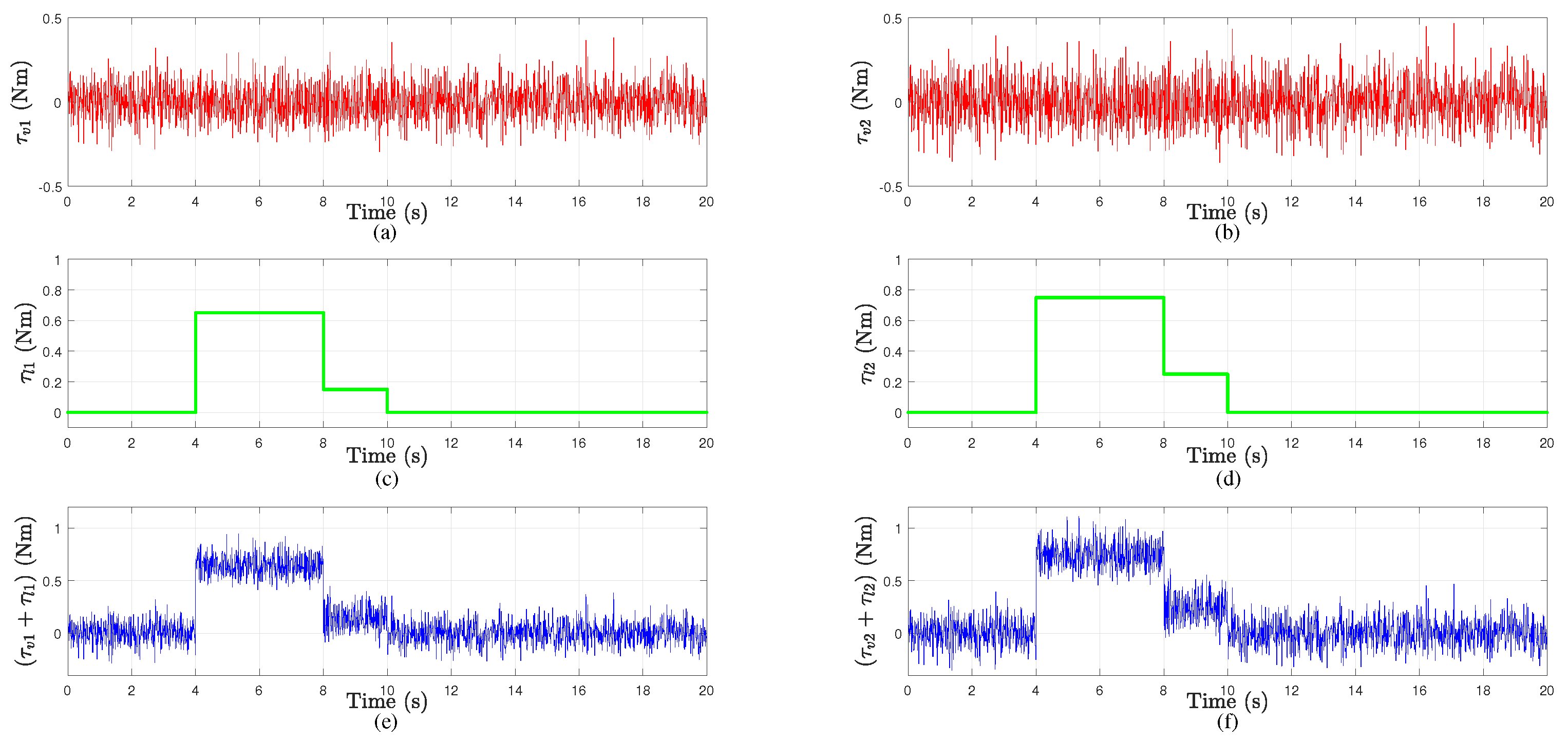
First, a disturbance torque of vibration τ v 1 τ v 2 T by a Gaussian noise is composed taking into account that it should be bounded. Therefore, a signal with a mean value = 0 0 T Nm, a variance = 0 . 01 0 . 015 T Nm, and a sampling time of 0 . 01 s is set. Then, the effect of the disturbance torque of the payload variation on the first and second joints is represented as follows:
τ l 1 = 0 . 65 Nm , 4 s t 8 s 0 . 15 Nm , 8 s t 10 s 0 , otherwise
τ l 2 = 0 . 75 Nm , 4 s t 8 s 0 . 25 Nm , 8 s t 10 s 0 , otherwise .
To provide further explanation, the effects of both disturbances on the first and second joints are plotted in Figure 2.
The combination of the disturbances is bounded as follows:
0 . 2873 Nm 0 . 3518 Nm τ v 1 + τ l 1 τ v 2 + τ l 2 0 . 9446 Nm 1 . 1108 Nm .
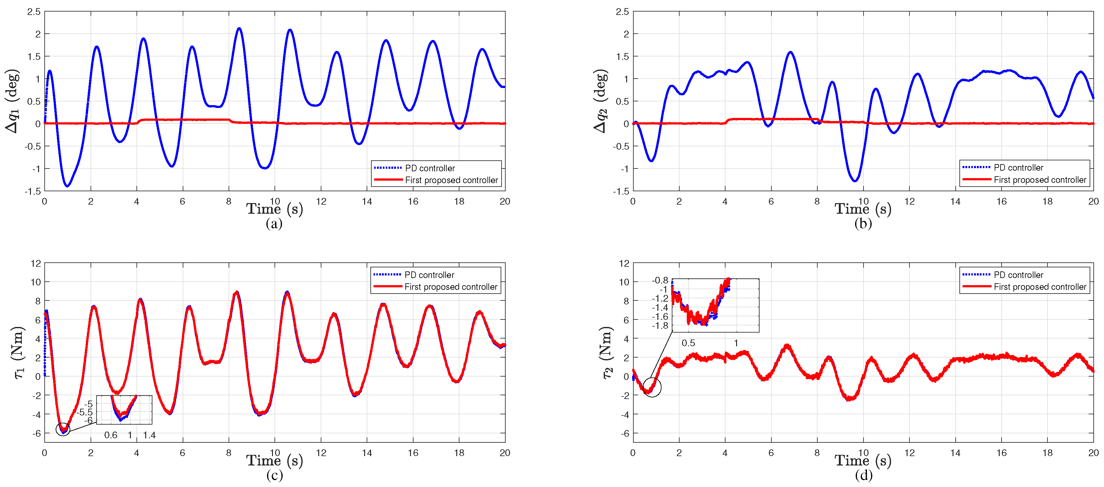
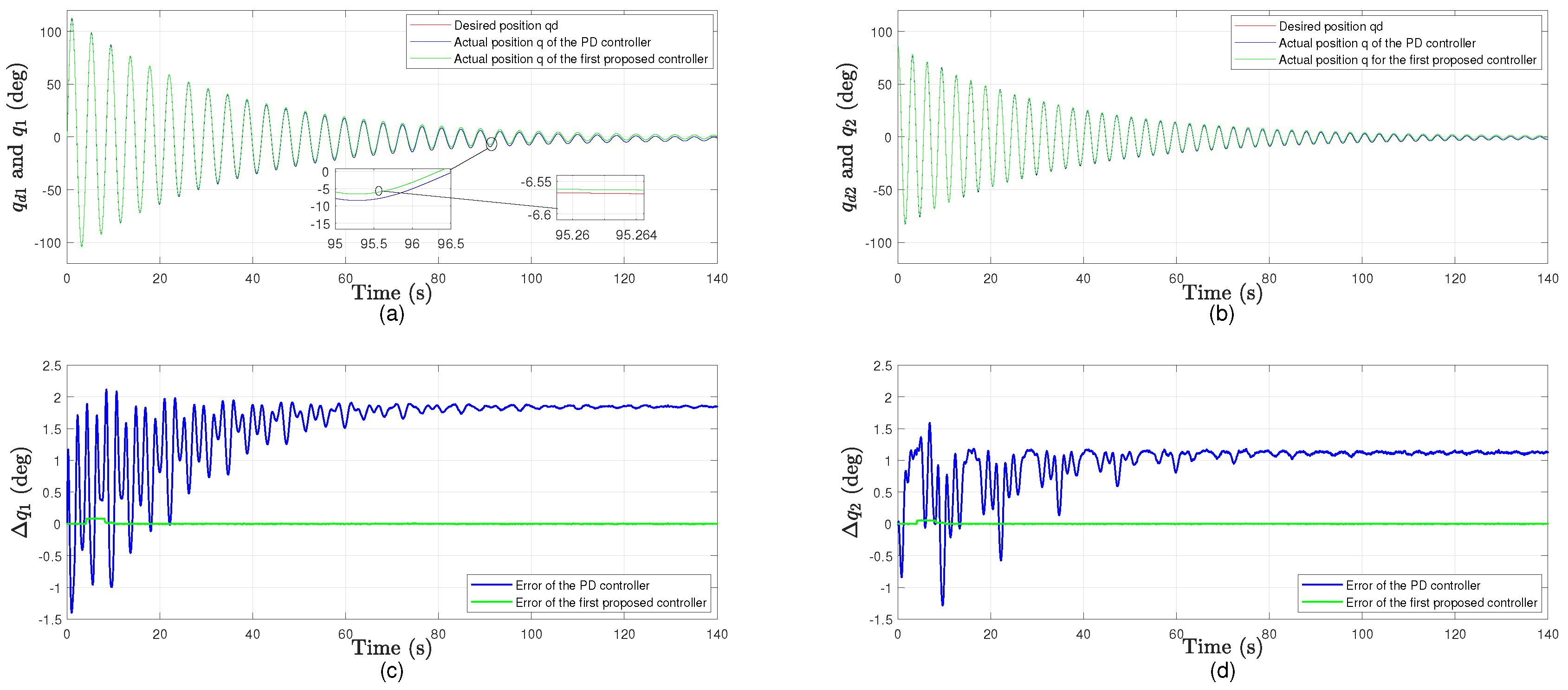
The control gains and design parameters in (12) are selected as K 1 = diag 40 60 , σ 1 = diag 10 12 , v b + l b = 1 . 50 Nm and d = 0 . 73 . The proportional and derivative gains for the PD control input in (38) are chosen to yield the best performance as K p = diag 225 100 , K d = diag 30 20 . The tracking errors and input torques of this approach are shown in Figure 3, where they are compared with the torques and errors obtained from the PD controller in (38). Although the PD control can reject the disturbances, the tracking errors are still large. By contrast, the proposed controller damps the same disturbances smoothly with less control efforts. Furthermore, the proposed controller performs rather well in terms of drifts and systematic errors as well. To show this, we run the simulation for 140 s and depict the actual displacements with their desired references and the errors between them in Figure 4.

4.2. Simulation Results for the Second Control Approach Based on the Bounded-Differentiable-Disturbance

As in the previous part, the disturbance signals are composed according to the assumptions of this approach. Therefore, we compose them as
τ v 1 + τ l 1 τ v 2 + τ l 2 = 0 . 25 s i n ( 2 t ) + 0 . 10 Nm 0 . 40 s i n ( 4 t ) + 0 . 15 Nm
where they are clearly bounded and differentiable. The bounded values for the overall disturbance can be directly calculated from the above equation and are
0 . 15 Nm 0 . 25 Nm τ v 1 + τ l 1 τ v 2 + τ l 2 0 . 35 Nm 0 . 55 Nm .
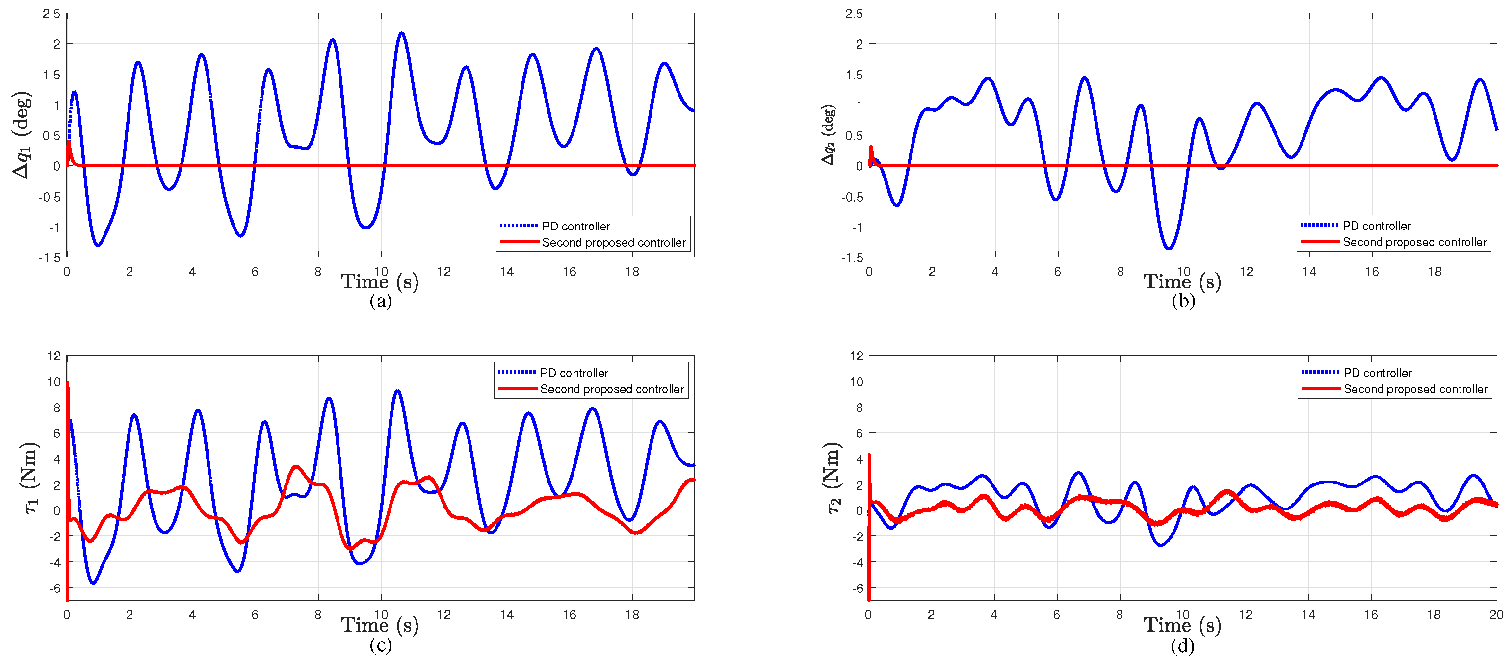
For this approach, we select the gains in (30) as K 2 = 75 , K 3 = 100 , σ 1 = diag 40 50 , and σ 2 = diag 30 40 . The performance of the control inputs for this approach is compared with the PD control as shown in Figure 5, where the gains and parameters of the PD control are the same as in Section 4.1.
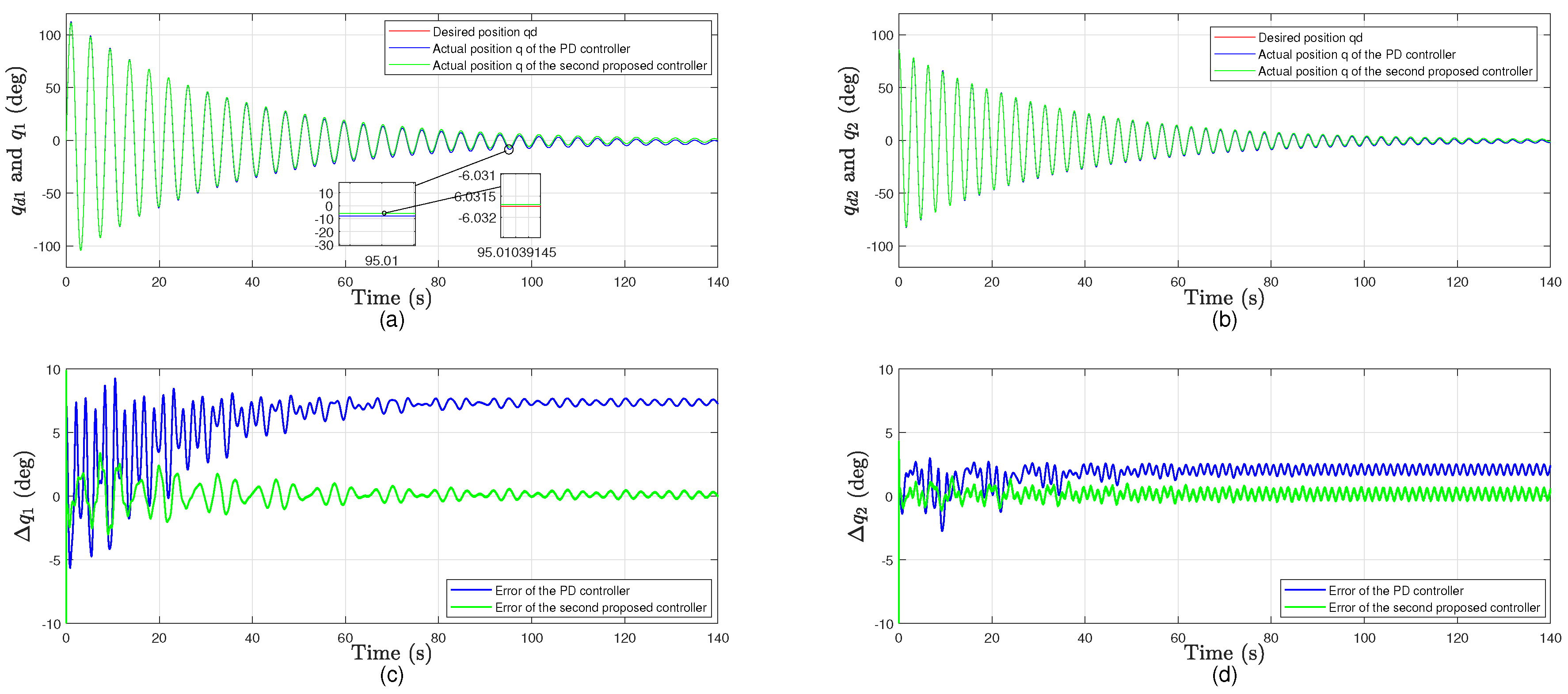
This controller performs better in terms of accuracy and control effort because it drives the error to zero, but it is restricted by Assumption 6. By contrast, the preceding controller drives the error to a value close to zero by only considering Assumption 1. Same as the preceding approach, the performance of the proposed controller in terms of drifts and systematic errors is presented in Figure 6.
In both proposed approaches, the torques have higher oscillations w.r.t. the PD controller; however, the oscillations are not beyond the classical bandwidth limits of the actuators.

4.3. Quantitative Analysis

In order to further compare and validate the performance of the proposed controllers, the following statistical indices are used:
  • Maximum absolute value of the error for each joint.
    Δ q i m a x = max j = 1 , . . , M ( Δ q i ( j ) ) .
  • Root mean square (rms) values of the error and input torque for each joint.
    Δ q i r m s = 1 M j = 1 M Δ q i ( j ) 2 .
    τ i r m s = 1 M j = 1 M τ i ( j ) 2 .
  • Percentage change in the rms values of the error and input torque for the proposed control approaches compared with the PD control.
    % c h a n g e Δ q i r m s = ( Δ q i r m s ) p r o p o s e d c o n t r o l l e r ( Δ q i r m s ) P D c o n t r o l l e r ( Δ q i r m s ) P D c o n t r o l l e r × 100 % ,
    % c h a n g e τ i r m s = ( τ i r m s ) p r o p o s e d c o n t r o l l e r ( τ i r m s ) P D c o n t r o l l e r ( τ i r m s ) P D c o n t r o l l e r × 100 %
where i is the joint number and M is the number of sampling steps of the simulation.
Table 2 and Table 3 summarize the performance for the both proposed approaches compared with the PD control. The indices in (39)–(41) for both joints are obtained from the results in Figure 3 and Figure 5.
Table 4 presents the percentage changes in (42) and (43) for each one of the proposed controller compared with the PD controller. Moreover, the time for evaluating control actions of both controllers compared with the PD controller are presented in Table 5.
From the above tables, which compare the performance of each control approach with the PD control, we deduce the following points:
  • The first approach reduces the average tracking errors of both joints by about 97% with almost the same control efforts.
  • The second approach reduces the average tracking errors and control efforts of both joints by about 98% and 81%, respectively.
  • The proposed controllers have higher computation time than that in the standard PD controller.

5. Conclusions

Two dedicated nonlinear approaches for tracking control of robot manipulators in joint space subject to uncertain torques due to vibration and payload variation are presented. In both approaches, a Lyapunov-based analysis is used to design the controllers and investigate their stability. The first approach relieves the restrictions of the uncertain torques’ characteristics and obtains a controller that yields a UUB tracking error. The uncertain torques in this approach need only to be bounded. The tracking error in the second approach yields an asymptotic result at the expense of an assumption that the uncertain torques are differentiable and bounded while considering the initial conditions of the states. Simulations are performed to validate the designed controllers and illustrate their performance in terms of accuracy, control efforts, and computation time. The designed controllers are compared with the PD controller and they show significant effect and superior control performance. The first proposed controller reduces the average rms values of the tracking errors by around 97% with almost the same rms values of the control efforts of the PD control. The second proposed controller reduces the average rms values of the tracking errors and control efforts by around 98% and 81%, respectively. The time necessary for evaluating control actions of the proposed controllers is higher than the time of the PD controller. However, this computation time is still less than that of advanced approaches and it is relatively small for modern CPUs.

Author Contributions

Conceptualization, M.M.M.; formal analysis, M.M.M., C.D.C., and I.H.; simulation code-writing, M.M.M.; supervision, C.D.C. and I.H.; writing-original draft, M.M.M. All authors have read and agreed to the published version of the manuscript.

Funding

This research received no external funding.

Conflicts of Interest

The authors declare no conflict of interest.

References

  1. Du, G.; Zhang, P.; Liu, X. Markerless human–manipulator interface using leap motion with interval Kalman filter and improved particle filter. IEEE Trans. Ind. Inform. 2016, 12, 694–704. [Google Scholar] [CrossRef]
  2. Slotine, J.J.E.; Li, W. On the adaptive control of robot manipulators. Int. J. Robot. Res. 1987, 6, 49–59. [Google Scholar] [CrossRef]
  3. Craig, J.J.; Hsu, P.; Sastry, S.S. Adaptive control of mechanical manipulators. Int. J. Robot. Res. 1987, 6, 16–28. [Google Scholar] [CrossRef]
  4. Hsia, T.S.; Lasky, T.; Guo, Z. Robust independent joint controller design for industrial robot manipulators. IEEE Trans. Ind. Electron. 1991, 38, 21–25. [Google Scholar] [CrossRef]
  5. Dawson, D.; Qu, Z.; Lewis, F.; Dorsey, J. Robust control for the tracking of robot motion. Int. J. Control 1990, 52, 581–595. [Google Scholar] [CrossRef]
  6. Spong, M.W. On the robust control of robot manipulators. IEEE Trans. Autom. Control 1992, 37, 1782–1786. [Google Scholar] [CrossRef]
  7. Slotine, J.J.E. The robust control of robot manipulators. Int. J. Robot. Res. 1985, 4, 49–64. [Google Scholar] [CrossRef]
  8. Yeung, K.S.; Chen, Y.P. A new controller design for manipulators using the theory of variable structure systems. IEEE Trans. Autom. Control 1988, 33, 200–206. [Google Scholar] [CrossRef]
  9. Nafia, N.; El Kari, A.; Ayad, H.; Mjahed, M. Robust interval type-2 fuzzy sliding mode control design for robot manipulators. Robotics 2018, 7, 40. [Google Scholar] [CrossRef] [Green Version]
  10. Leahy, M.; Johnson, M.A.; Rogers, S.K. Neural network payload estimation for adaptive robot control. IEEE Trans. Neural Netw. 1991, 2, 93–100. [Google Scholar] [CrossRef]
  11. Kwan, C.; Lewis, F.L.; Dawson, D.M. Robust neural-network control of rigid-link electrically driven robots. IEEE Trans. Neural Netw. 1998, 9, 581–588. [Google Scholar] [CrossRef] [PubMed]
  12. Gao, H.; He, W.; Zhou, C.; Sun, C. Neural network control of a two-link flexible robotic manipulator using assumed mode method. IEEE Trans. Ind. Inform. 2018, 15, 755–765. [Google Scholar] [CrossRef]
  13. Zhang, F.; Dawson, D.M.; de Queiroz, M.S.; Dixon, W.E. Global adaptive output feedback tracking control of robot manipulators. IEEE Trans. Autom. Control 2000, 45, 1203–1208. [Google Scholar] [CrossRef]
  14. Dixon, W.E.; Zergeroglu, E.; Dawson, D.M. Global robust output feedback tracking control of robot manipulators. Robotica 2004, 22, 351–357. [Google Scholar] [CrossRef] [Green Version]
  15. Cai, Z.; de Queiroz, M.S.; Dawson, D.M. Robust adaptive asymptotic tracking of nonlinear systems with additive disturbance. IEEE Trans. Autom. Control 2006, 51, 524–529. [Google Scholar] [CrossRef]
  16. Patre, P.M.; MacKunis, W.; Makkar, C.; Dixon, W.E. Asymptotic tracking for systems with structured and unstructured uncertainties. In Proceedings of the 45th IEEE Conference on Decision and Control, San Diego, CA, USA, 13–15 December 2006; pp. 441–446. [Google Scholar]
  17. Makkar, C.; Hu, G.; Sawyer, W.G.; Dixon, W.E. Lyapunov-based tracking control in the presence of uncertain nonlinear parameterizable friction. IEEE Trans. Autom. Control 2007, 52, 1988–1994. [Google Scholar] [CrossRef]
  18. Patre, P.M.; MacKunis, W.; Kaiser, K.; Dixon, W.E. Asymptotic tracking for uncertain dynamic systems via a multilayer neural network feedforward and RISE feedback control structure. IEEE Trans. Autom. Control 2008, 53, 2180–2185. [Google Scholar] [CrossRef]
  19. Shao, X.; Meng, Q.; Liu, J.; Wang, H. RISE and disturbance compensation based trajectory tracking control for a quadrotor UAV without velocity measurements. Aerosp. Sci. Technol. 2018, 74, 145–159. [Google Scholar] [CrossRef]
  20. Su, Z.; Xie, M.; Li, C. RISE based active vibration control for the flexible refueling hose. Aerosp. Sci. Technol. 2019, 92, 387–404. [Google Scholar] [CrossRef]
  21. Pedroza, N.; MacKunis, W.; Golubev, V. Robust nonlinear regulation of limit cycle oscillations in uavs using synthetic jet actuators. Robotics 2014, 3, 330–348. [Google Scholar] [CrossRef] [Green Version]
  22. Fischer, N.; Hughes, D.; Walters, P.; Schwartz, E.M.; Dixon, W.E. Nonlinear RISE-based control of an autonomous underwater vehicle. IEEE Trans. Robot. 2014, 30, 845–852. [Google Scholar] [CrossRef] [Green Version]
  23. Economou, D.; Lee, C.; Mavroidis, C.; Antoniadis, I. Robust vibration suppression in flexible payloads carried by robot manipulators using digital filtering of joint trajectories. In Proceedings of the International Symposium on Robotics and Automation, Monterrey, Mexico, 10–12 November 2000; pp. 244–249. [Google Scholar]
  24. Mamani, G.; Becedas, J.; Feliu, V. Sliding mode tracking control of a very lightweight single-link flexible robot robust to payload changes and motor friction. J. Vib. Control 2012, 18, 1141–1155. [Google Scholar] [CrossRef]
  25. Feliu, V.; Castillo, F.; Jaramillo, V.; Partida, G. A Robust Controller for A 3-DOF Flexible Robot with a Time Variant Payload. Asian J. Control 2013, 15, 971–987. [Google Scholar] [CrossRef]
  26. Gu, D.W.; Petkov, P.; Konstantinov, M.M. Robust Control Design with MATLAB®; Springer Science & Business Media: Berlin/Heidelberg, Germany, 2005. [Google Scholar]
  27. From, P.J.; Schjølberg, I.; Gravdahl, J.T.; Pettersen, K.Y.; Fossen, T.I. On the boundedness and skew-symmetric properties of the inertia and Coriolis matrices for vehicle-manipulator systems. IFAC Proc. Vol. 2010, 43, 193–198. [Google Scholar] [CrossRef] [Green Version]
  28. Dixon, W.E.; Behal, A.; Dawson, D.M.; Nagarkatti, S.P. Nonlinear Control of Engineering Systems: A Lyapunov-Based Approach; Springer Science & Business Media: Berlin/Heidelberg, Germany, 2013. [Google Scholar]
  29. Crane III, C.D.; Duffy, J. Kinematic Analysis of Robot Manipulators; Cambridge University Press: New York, NY, USA, 2008. [Google Scholar]
  30. Slotine, J.J.E.; Li, W. Applied Nonlinear Control; Prentice Hall: Englewood Cliffs, NJ, USA, 1991. [Google Scholar]
  31. Khalil, H. Nonlinear Systems; Prentice Hall: Englewood Cliffs, NJ, USA, 2002. [Google Scholar]
  32. Desoer, C.A.; Vidyasagar, M. Feedback Systems: Input-Output Properties; Academic Press: New York, NY, USA, 1975. [Google Scholar]
  33. Lewis, F.L.; Dawson, D.M.; Abdallah, C.T. Robot Manipulator Control: Theory and Practice; Marcel Dekker: New York, NY, USA, 2004. [Google Scholar]
  34. Craig, J. Adaptive Control of Mechanical Manipulators; Addison-Wesley: Boston, MA, USA, 1988. [Google Scholar]
  35. Kokotovic, P.V. The joy of feedback: Nonlinear and adaptive. IEEE Control Syst. Mag. 1992, 12, 7–17. [Google Scholar]
  36. Xian, B.; De Queiroz, M.S.; Dawson, D.M. A Continuous Asymptotic Tracking Control Strategy for Uncertain Nonlinear Systems. IEEE Trans. Autom. Control 2004, 49, 1206–1211. [Google Scholar] [CrossRef]
Figure 1. Scheme of the simulated robot and the first controller.
Robotics 09 00002 g001
Figure 2. Disturbance torques due to vibration and payload variation for the first approach: (a,b) vibration effect; (c,d) payload variation effect; and (e,f) effect of combination on joint 1 and joint 2, respectively.
Robotics 09 00002 g002
Figure 3. Tracking errors and control inputs for the first proposed approach compared with the proportional derivative (PD) approach: (a,b) angular displacement errors of joint 1 and joint 2, respectively; (c,d) input torques of joint 1 and joint 2, respectively.
Robotics 09 00002 g003
Figure 4. Performance in terms of drifts and systematic errors for the first proposed approach compared with the PD approach: (a,b) desired and actual displacements of joint 1 and joint 2, respectively; (c,d) angular displacement errors of joint 1 and joint 2, respectively.
Robotics 09 00002 g004
Figure 5. Tracking errors and control inputs for the second proposed approach compared with the PD approach: (a,b) angular displacement errors of joint 1 and joint 2, respectively; (c,d) input torques of joint 1 and joint 2, respectively.
Robotics 09 00002 g005
Figure 6. Performance in terms of drifts and systematic errors for the second proposed approach compared with the PD approach: (a,b) desired and actual displacements of joint 1 and joint 2, respectively; (c,d) angular displacement errors of joint 1 and joint 2, respectively.
Robotics 09 00002 g006
Table 1. Physical parameters of the two-link manipulator.
SymbolDescriptionValueUnit
m 1 Mass of link 1 0.5 kg
m 2 Mass of link 2 0.4 kg
l 1 Length of link 1 0.6 m
l 2 Length of link 2 0.5 m
Table 2. Performance summary for the first roposed approach compared with the PD control.
IndexesPD ControlFirst Approach
Δ q 1 m a x (deg) 2.0981 0.0878
Δ q 2 m a x (deg) 1.5781 0.0590
Δ q 1 r m s (deg) 1.0455 0.0374
Δ q 2 r m s (deg) 0.8487 0.0253
τ 1 r m s (Nm) 4.3128 4.2933
τ 2 r m s (Nm) 1.5666 1.5719
Table 3. Performance summary for the second proposed approach compared with the PD control.
IndexesPD ControlSecond Approach
Δ q 1 m a x (deg) 2.1450 0.2198
Δ q 2 m a x (deg) 1.4325 0.1181
Δ q 1 r m s (deg) 1.0459 0.0160
Δ q 2 r m s (deg) 0.8636 0.0085
τ 1 r m s (Nm) 4.3161 1.4940
τ 2 r m s (Nm) 1.6011 0.5494
Table 4. Percentage changes of the errors and input torques for the proposed control approaches compared with the PD control.
IndexesFirst ApproachSecond Approach
% c h a n g e Δ q 1 r m s 96.40 98.47
% c h a n g e Δ q 2 r m s 97.01 99.01
% c h a n g e τ 1 r m s 0.45 68.38
% c h a n g e τ 2 r m s + 0.33 96.565
Table 5. Performance in terms of computation time for the proposed control approaches compared with the PD control.
ControllerNo. of CallsTime/Call (ms)Total Time (s)
PD controller20552 0.003 0.062
First controller76695 0.007 0.536
Second controller934670 0.005 4.67