1. Introduction
Agricultural robotics represents a great opportunity for farms to face the manual labor outflow from land and the transformation from labor-intensive industry into mechanized plants, both caused by social, technological, and economic matters [
1]. Moreover, the introduction of robots can make small-scale operations more feasible, helping small producers not to suffer the current agribusiness model, which requires large resources to pursuit greater yields [
2]. The key factors are the better effectiveness and the efficiency that robots guarantee compared to manual labor, the latter representing a major component of the total cost in traditional field operation. These aspects assume significant value considering that the 80% of the tasks commonly conducted by humans can now be carried out by robots, thus reducing the gap between actual and potential yield [
3]. The reason lies in recent developments in robotics and artificial intelligence, which can be applied to perform non-standard tasks, i.e., by imitating human skills and improving them to expand the application cases, including the ability to work in various environmental conditions. In fact, today agricultural robots are becoming more and more complex machines as they should enclose in a compact package the abilities of guidance, detection, action, and mapping, which are not independent and must be usually handled in synergy to satisfy a wide range of applications [
4].
A recent review of the state-of-the-art of agricultural robotics identifies three main categories: weed control, field scouting, and harvesting [
5]. The first class is characterized by wheeled platform mounting sprays and sensors for weed detection, chemical control, and fertilizer application [
6,
7,
8,
9,
10]. An example is the lightweight farm vehicle AgBot II developed by the Queensland University of Technology for weed detection, spot-spraying, and mechanical weed removal [
6]; similarly, the partnership between the University of Osnabrueck, the Amazonen-Werke and the Robert Bosch Gmbh company, produced the BoniRob, a multipurpose field robot for soil monitoring, weed phenotyping and precision spray application [
7]; also the Swiss Ecorobotix company has recently developed the AVO and ARA wheeled autonomous robots powered by solar panels, with sprays and sensors for weed control [
8]. The second group of agricultural robots distinguishes by mounting dedicated environmental sensors and robotic arms for precision maneuvers or field samples collection [
11,
12,
13,
14]. For instance, GRAPE is a ground robot funded by the European Union’s, designed for vineyard health protection and monitoring; specifically, it mounts a six degrees of freedoms (DOFs) robotic arm whose main goal is the dexterous manipulation and the correct deployment of a pheromone dispenser [
11]. Another example is the Trimbot2020, funded by the EU H2020 program, whose target is the development of an algorithmic concept to guide a modified version of the commercial Bosch Indego, equipped with six DOFs manipulator on a stabilized platform for automatic bush trimming [
12]. In addition, the Australian Centre for Field Robotics at The University of Sydney designed the Ladybird robot for the vegetable industry, equipped with a four-wheel driving system, solar panels, and a 6-DOFs arm [
13]. Finally, harvesting agricultural robots integrate more accurate vision sensors and algorithms to guide properly designed end-effectors [
15,
16]. In some cases, the robotic arm is mounted on a single DOF mobile platform to adapt the robot workspace to plant profiles. For example, a project supported by the National Technology Research and Development Program of China, proposed a custom designed tool and a lifting support for tomatoes harvesting [
17]. Other studies focuses on vision-based algorithms for fruit targeting, as showed in recent works by the Department of Computing Science of Umeå University, which aims to automate the harvest of sweet pepper in greenhouses proposing RGB vision servo control [
18], or by Washington State University, which focuses on depth camera-based techniques for robotic cherry harvesting [
19]. In general, the design of agricultural mobile robots for grasping activities is considered the most challenging because of the complexity of the mechatronic system [
20].
All the mentioned works, and overall, the existing agriculture robots, are designed for specific tasks and even when integrating a robotic arm, can operate within a limited workspace. For instance, the robots with grasping capabilities [
11,
12] are built from commercial mobile robot by attaching a robotic arm in a fixed configuration; the Ladybird robot [
13] integrates solar panels and a robotic arm, but does not permit to move the arm base depending on the task. The agricultural robots of the harvesting class [
15,
16,
17] show interesting solutions to move the mobile platform and the harvesting tool in order to reach the fruits, but the range of motion of the end-effector is limited. To overcome this constraints, some concepts are moving toward modular robot that are able to re-configure their operating range and size. In this context, the proposal by the Haifa Faculty of Civil and Environmental Engineering in the Israelian Technion Autonomous Systems Program is a modular mobile robot with the ability to re-configure the kinematic chain of the mounted robotic arm; in function of the task, the robot is assembled in different ways, opening to two harvest scenario [
21]. Even the latest Thorvald II robot, a project by the Faculty of Science and Technology in Norwegian University, is designed with a software-hardware modularity, to be assembled in several ways and to work in greenhouse or open fields, or whether the crop is wheat or strawberry [
22]. When flexibility is required, re-configurable robots represent a concrete solution, but suffer the need to be physically disassembled and re-built to adapt to plant species or task requirements.
This work introduces Agri.q, a unique precision agriculture robot with novel kinematics, which integrates a seven DOFs manipulator in order to obtain an augmented workspace. In particular, the robotic arm is attached to a mobile frame, which has an active position mechanism to modify the rover configuration and passive kinematic elements to compensate terrain irregularities or slopes. Moreover, Agri.q mounts vision sensors and an orientable landing platform for drones made of solar panels, which enables multi-robot strategies and promote sustainable energy. The result is a lightweight wheeled UGV with a mass of 100 kg, for crop health monitoring, protection, and dexterous operations. In terms of weight, the cited ARA from Ecorobotix [
8] has a mass of 130 kg, but it shows a different kinematics with four wheels and is not designed to accommodate a robotic manipulator. Compared to the state-of-the-art, this paper brings a new agriculture robot concept designed to be flexible with an easy structure, enclosing the insights of modular robots and the simple mechanics of traditional ones. The robotic arm integration is also a relevant aspect, since in many of the previous works the arm is attached to mobile robots in some positions, without discussing this choice in terms of workspace.
2. The Mission: Intelligent Vineyard Healthcare
The PIC4SeR (Politecnico Interdipartmental Centre for Service Robotics) is the interdepartmental center of Politecnico di Torino, which synthetizes affine knowledge domains to solve different application scenarios with Service robotics [
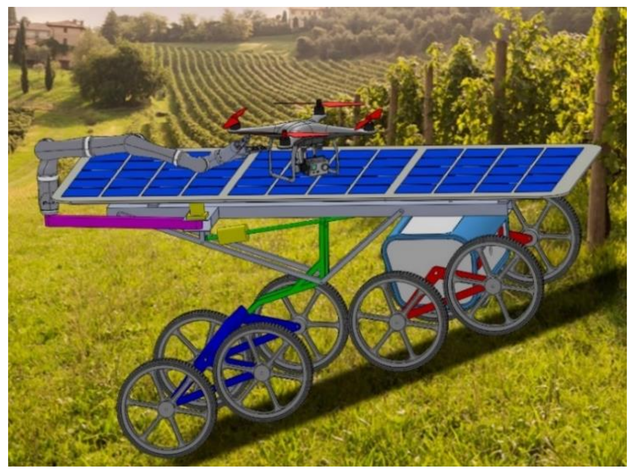
23]. In particular, the Agri.q UGV is part of the PIC4SeR mission for intelligent vineyard healthcare. In this perspective, viticulture is one of the main activities that would benefit from digital farming. Monitoring and mapping can be carried out both using air and ground modules by means of dedicated sensors, while grasping operations would involve specific grippers mounted on the UGV. In fact, the main goal of the ground module is to navigate to specific region of the vineyard to collect samples from soil and plants, or to apply fertilizers. Therefore, it must be able to move on irregular terrains and to approach vines with a robotic arm to perform dexterous operations. An interesting scenario is represented by the combined use of UGV and drones to take the samples from the field to a base station, where data is analyzed. Thus, a landing platform on the vehicle should be considered to enable hard docking and physical interaction with drones.
Figure 1 shows a scenario of the vineyard mission, involving a UAV and UGV with a landing platform for the drone and a robotic arm.
Table 1 shows the UGV design requirements. The size of the rover and the reachable height of the robotic arm result from traditional vineyard morphology, which shows a minimum vine rows distance of 1.5 m and a maximum plant height of about 2 m [
24]; furthermore, a limited weight is needed to preserve the ground integrity and to reduce the energy consumption. Concerning the landing area, it should easily accommodate a drone with a takeoff weight of 7 kg and a diagonal wheelbase of 650 mm. The platform should be kept horizontal above the soil to allow a drone docking even on irregular terrain or steep slopes; therefore, a positioning mechanism should be provided. In order to maximize the rover autonomy, the landing platform should be covered by solar panels; this way, the same positioning mechanism used for the platform orientation could be exploited to maximize the sun rays collection during the charging phase. Finally, to increase the dexterity of the manipulator, a 7 degrees of freedom robotic arm type with spherical wrist should be integrated into the rover.
3. Rover Agri.q02
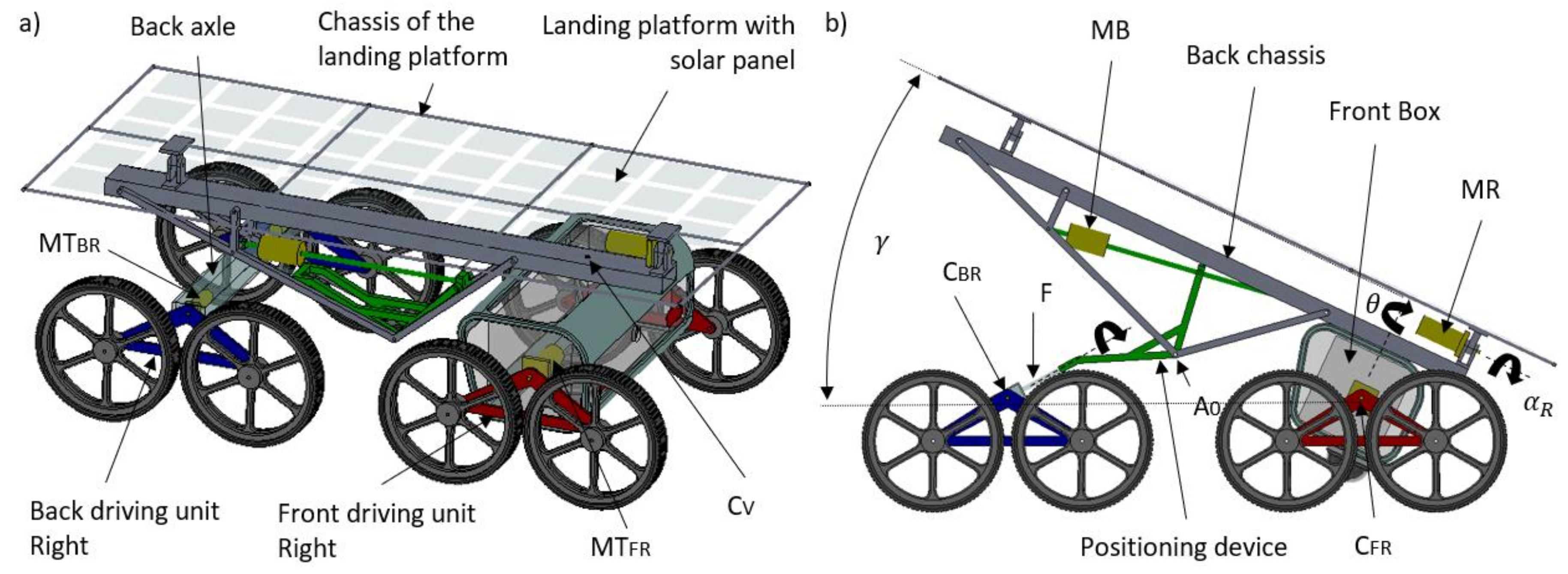
The specifications for the intelligent vineyard healthcare mission lead to the rover Agri.q02, whose functional design is showed in
Figure 2. Agri.q02 is the name of the latest version of the Agri.q. In fact, the basic concept of Agri.q, also known as Agri.q01, was introduced in a previous work [
25] and upgraded to the revised Agri.q02 in [
26], where the kinematics has been precisely discussed. Therefore, in this work only the main aspects of the Agri.q02 are summarized. Since the functional architecture of the rover components is symmetrical with respect to the longitudinal axis, hereafter the name of the components representing left and right sides will be denoted with subscripts L and R respectively; with the same logic, the front and the back of the rover will be identified by F and B. The front box is connected to the front driving units through the joints C
FR and C
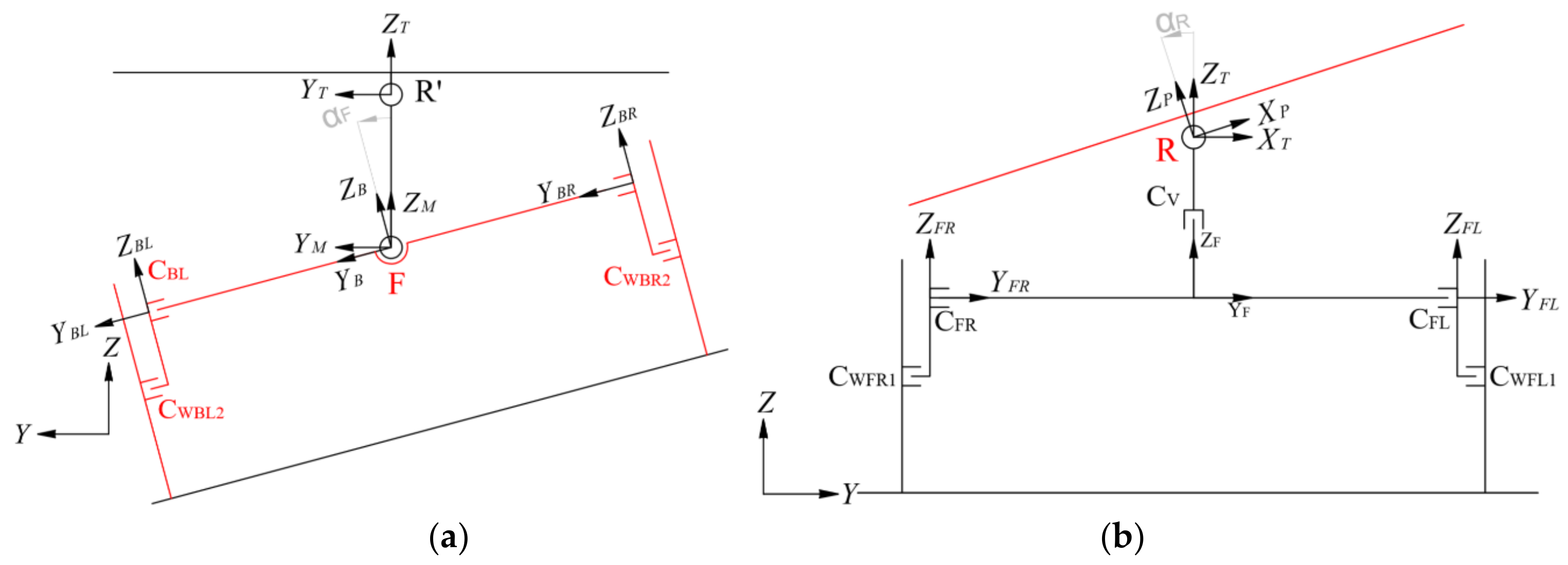
FL. Each front driving unit is composed of a pair of wheels mounted on a rocker arm, which can freely rotate by an angle Ω
F in the vertical plane about the C
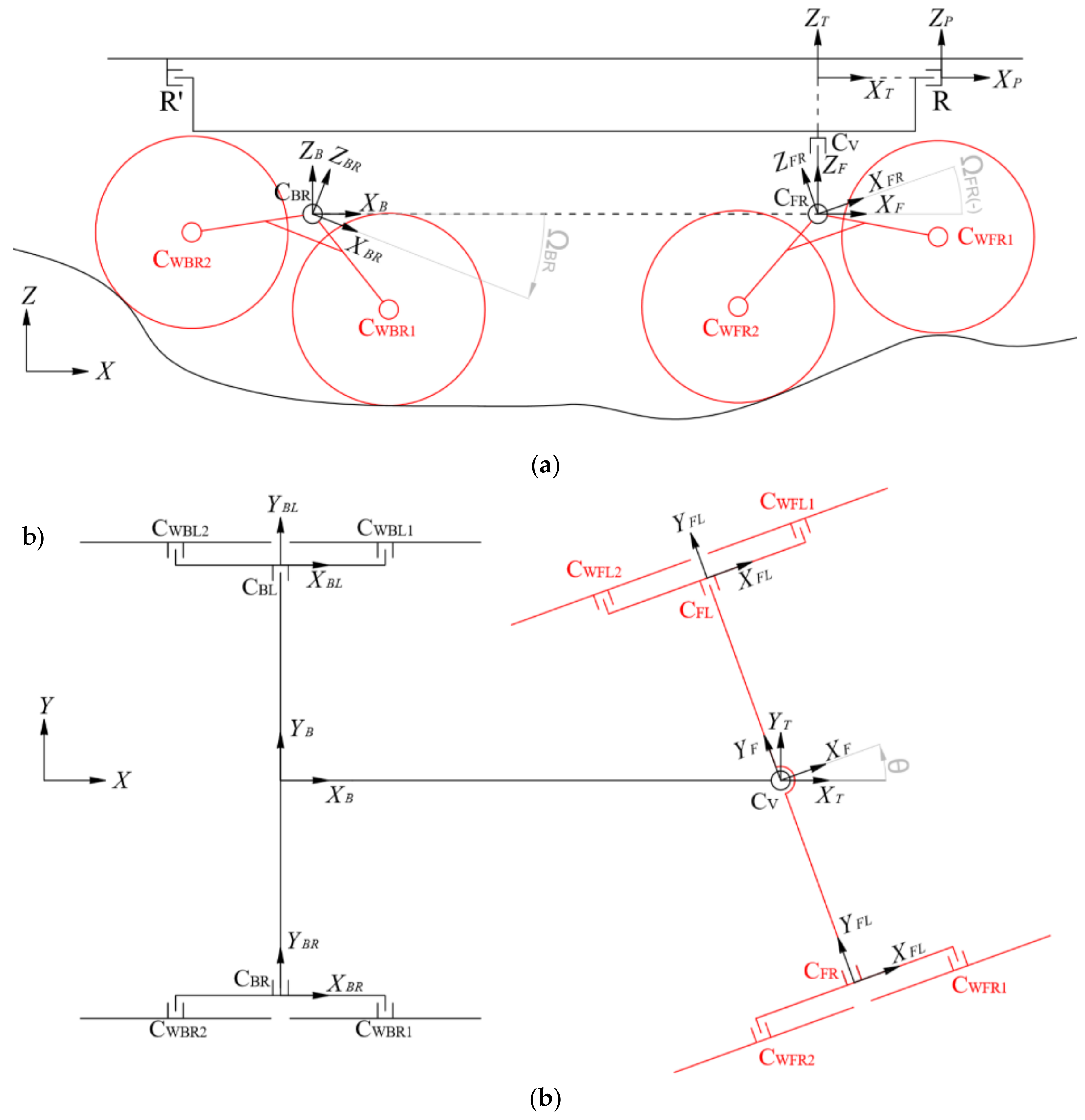
F axis to ensure the contact between the wheels and the terrain, even in presence of obstacles or irregularities of the ground (
Figure 3a). Two motors MT
FR and MT
FL are mounted on each side to power the wheels through a transmission chain. Thus, by controlling the rotational speeds of the right and left wheels of the front units, it is possible to define the trajectory of the rover. The back chassis is connected to the front box by means of the joint C
V, which enables relative rotation θ in the horizontal plane (
Figure 3b).
A positioning mechanism links the back chassis to the back axle, which holds on each side the rocker arms of the back-driving units via C
BR and C
BL. As before, also the back rocker arms can freely rotate about the C
B axis by the angle Ω
B. Two motors MT
BR and MT
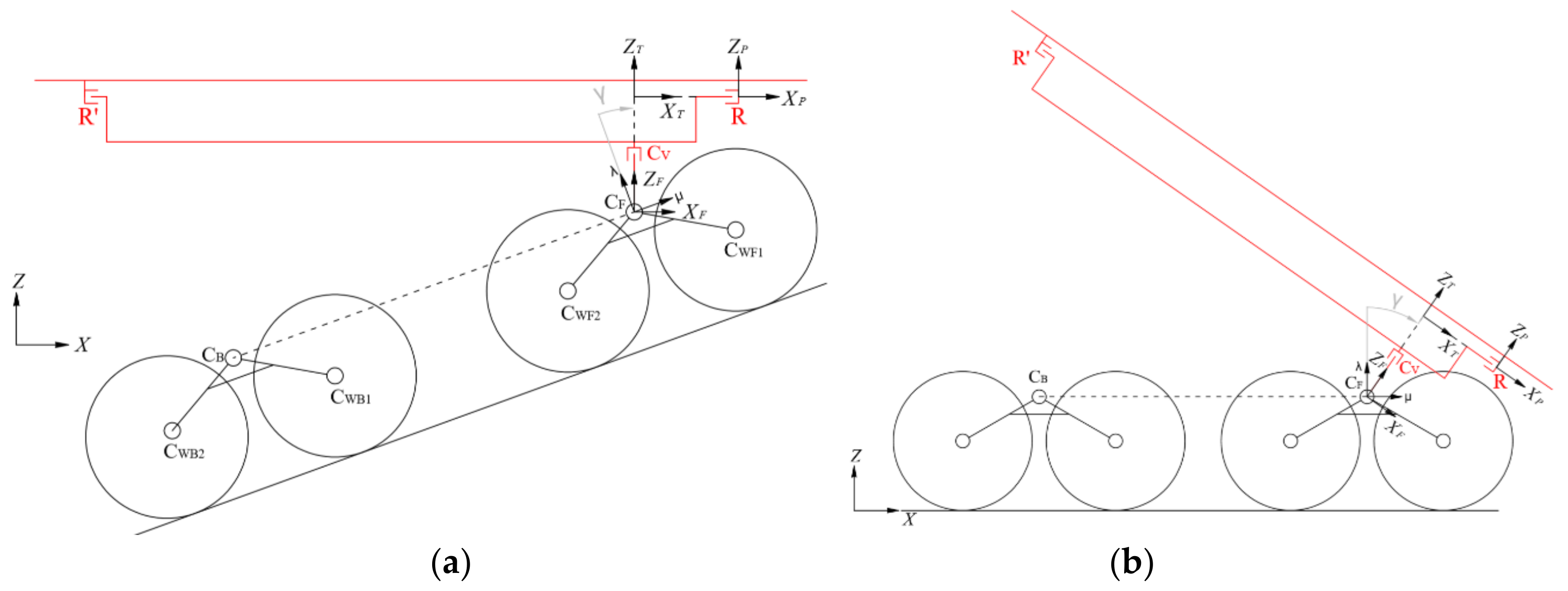
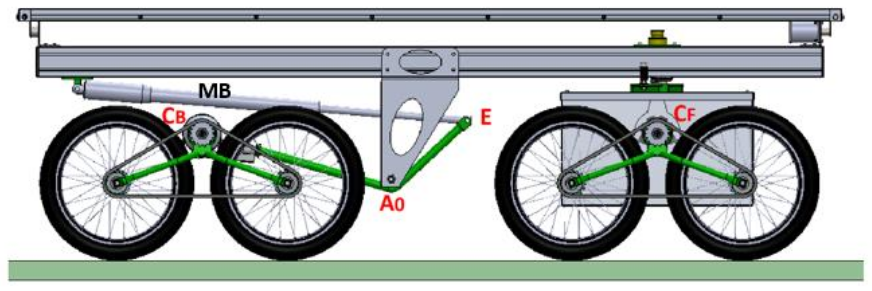
BL apply torque to the back wheels so to permit the Agri.q02 to climb steep hills. Owing to the joint F, the back axle can rotate to adapt to soil irregularities. A pitch turning motion of the platform made of photovoltaic panels permits to keep it horizontal above the soil while the rover is facing steep climbs and to orient the panels in order to optimize the sunlight collection during the charging phase (
Figure 4). This turning motion is driven by the linkage C
B - A
0 - E, which is connected at C
B to the back axle shaft and pivoted on the chassis at A
0 (
Figure 5). A ball screw linear actuator MB actuates the linkage at E. The dimensional synthesis of the mechanism, using the kinematic inversion technique, is discussed in detail in [
26]. Finally, the landing platform is attached to the back chassis by the joint R, which is motorized to control the roll angle α
R, so to compensate transversal slopes (
Figure 6).
The rover electronic power system and its control components are stored in the front box. The result is a robot with 8 degrees of freedom, 6 of which are passive while the other 2 are motorized and controlled, as summarized in
Table 2. The high mobility of the rover derives from the mechanical synthesis of the vineyard mission specifications. In fact, conveniently combining passive and active DOFs, it is possible to drive the Agri.q02 on different terrain conditions, i.e., with irregularities and slopes, while maintaining the landing platform horizontal. In addition, the motion of the back chassis can be used to adjust the rover configuration according to the task. For instance, the integration with the robotic arm represents a key point since, depending on the position of the robot base on the rover, different scenarios would arise if the chassis is controlled to move the manipulator workspace.
4. Robotic Arm
The robot is designed for crop monitoring and weed control purposes. It must be able to collect ground and leaves samples at heights up 2 m, or to treat plants with fertilizer. In addition, the possibility to interact with a drone on the landing platform, e.g., handing over the collected samples to the drone, should be considered. To complete the foreseen tasks, it is essential to integrate the rover with a robotic arm. Specifically, the maximum reach of the arm has to be such as to enable dexterous manipulation on plants and terrain, as well as to cover the portion of the platform where the drone is docked. The workspace should be symmetrical to execute the different tasks in any direction. The kinematic redundancy would unlock the possibility to continuously drive the end-effector along a certain path with different arm configuration, which exploits flexibility while dealing with constrained environments. Concerning the payload, the arm should be as light as possible and capable to handle masses of at least 0.5 kg.
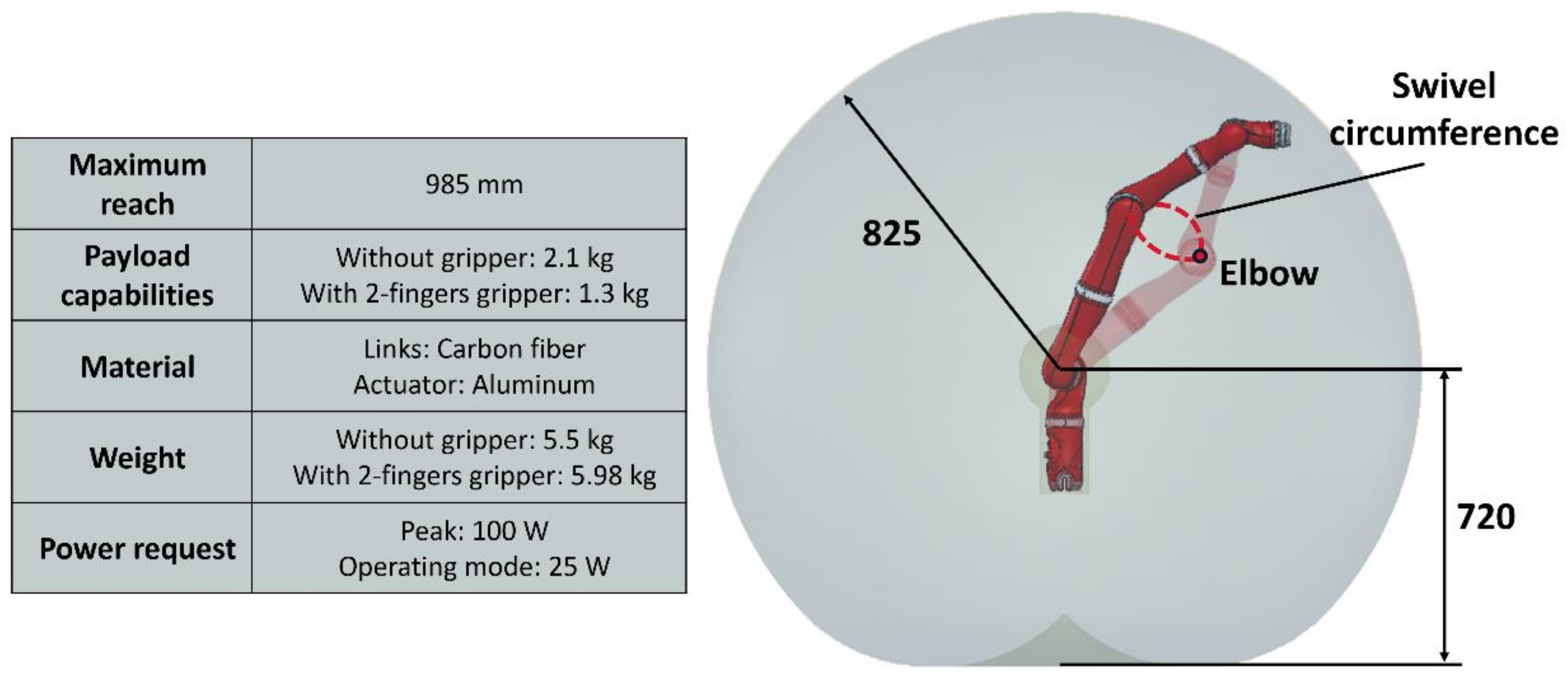
Given the requirements, the collaborative robot Kinova Jaco2 have been selected [
27]. In
Figure 7 the main features of the Jaco2 are presented. It is a 7 DOFs manipulator characterized by low weight, adequate payload, and a quasi-spherical workspace with a radius of 825 mm. Depending on the task, different tools can be designed and mounted on the robot flange. The Kinova 2-finger gripper, for example, increases the maximum reach up to 985 mm and enables grasping. In
Figure 7 the kinematic redundancy is also exploited introducing the swivel circumference, which is defined by the positions that the robot elbow can assume without modifying the pose of the end effector. This capability plays an important role in motion planning, making possible to avoid collision between the robot links and obstacles while driving the end-effector, with a defined orientation, along a certain path. In this case, the local control strategies and collision avoidance algorithms of previous works can be used [
28,
29,
30,
31]. They allow to dynamically define the robot trajectory with joint velocity sets, resulting from attractive-repulsive potential fields.
5. Rover-Robotic Arm Integration
5.1. Functional Integration
In the previous chapters, the design of the rover mechanics and the characteristics of the selected robotic arm have been described. The rover results in a high mobility platform, whose configuration can be adjusted in relation to the task and the environment. The robot is a redundant manipulator that can carry out dexterous tasks within a quasi-spherical workspace. The idea behind the integration is to mount the Jaco2 on the rover with a task-oriented optimization, merging the strengths of the two single devices to realize a flexible agricultural robot. It must be noticed that the integration process is not straightforward since the manipulator base position relative to the rover may affect the performance of the entire robot. First, the manipulator cannot be placed on the landing platform to keep the landing area clear and not to affect the solar panel efficiency during the charging phase. Moreover, the closer is the robotic arm base to the centroid of the rover, the higher is the reduction of the manipulator workspace because of the mechanical interferences. On the other hand, the total size of the Agri.q02 should be kept compact to enable maneuvers between the vineyards. Concerning the tasks, the arm gripper should be able to reach plants up to 2 m and the soil, as well as to physically interact with the drone docked on the platform.
Because of these constraints, in the previous work a beam connected to the back chassis by a revolute joint has been selected as mobile support for the robotic arm [
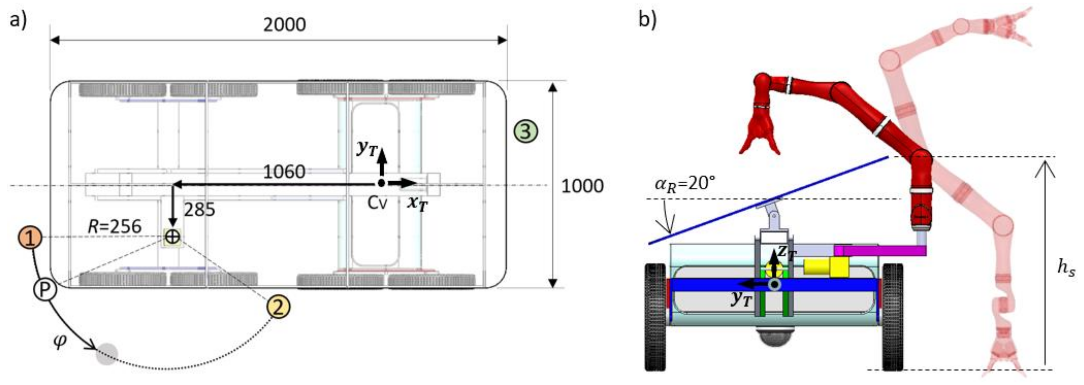
32]. This mechanism was designed starting from three crucial positions of the robot base relative to the rover. In
Figure 8a, these positions are named 1, 2, and P. In the same picture, the coordinates of the revolute joint with respect to the rover frame x
T-y
T-z
T are indicated. Position 1 and 2 represent two operative points; the point P was considered to define the length of the mobile support as the radius
R of the circumference that crosses 1 and 2 passing close by the rover corner. The main advantage is the possibility to place the arm base in any of the points within 1 and 2, by activating the degree of freedom
φ; the drawback is the need of a support actuation system, which would increase the rover weight and complexity.
In this work, a new solution based on fixed mounting points is presented. In particular, three mounting positions for the Jaco2 have been identified, as shown in
Figure 8a. Position 1 and 2 have been maintained from the previous solution; point 3 is analogous to 1, but on the opposite edge. For each position, the robot arm base is screwed on a support which is fixed to the back chassis. Therefore, the absolute position of the manipulator base is a function of the pitch angle.
In position 1 the interference between the Jaco2 workspace and the platform is minimized, while the movement of the arm because of the pitch angle is maximized. Here Agri.q02 is able to locate the arm workspace within the entire range of the pitch angle γ. The minimum value of γ places the arm close to the soil; with the maximum γ the arm can operate up to 2.5 m. For these reasons, position 1 can be suitable for high vineyards, or for applications that require the maximum dexterity for plants or terrain sampling.
If the Jaco2 is mounted in position 2, a larger portion of the workspace overlaps with the platform. Interacting with the drone becomes easier, but the reachable height related to pitch set is reduced. The arm workspace coverage is balanced, since it is possible to operate on the platform, near the soil and on the vines across the long edge of the rover. The robot shoulder center is positioned at a distance
hs = 775 mm from the soil, which is also the height at which the rolling angle α
R does not place the panel side above the shoulder joint, as depicted in
Figure 8b. This will prevent from compromising on-panel operations even when the roll is activated to compensate inclined terrain. In general, position 2 is suitable for most of the applications where the increase of the Agri.q02 outer size in the longitudinal direction, because of the arm, does not limit entering in the vineyard rows.
Position 3 is obtained by mirroring position 1 sequentially with respect to the median yT-zT and xT-zT planes of the rover. In this position, increasing the pitch angle affects the z coordinate of the robot base, approaching the arm to the terrain. It could be the best choice for soil treatments and sampling missions. In the next section, the effective Agri.q02 workspace is discussed and compared to the previous solution based on the rotating beam.
5.2. Indexes for the Evaluation of the Augmented Robotic Workspace
In this subsection, indexes to evaluate the variation of the robotic workspace resulting from a change of position of the robot base are reported. Moreover, a comparison between the indexes presented in [
32] with the mobile support and the ones with fixed mounting points is discussed.
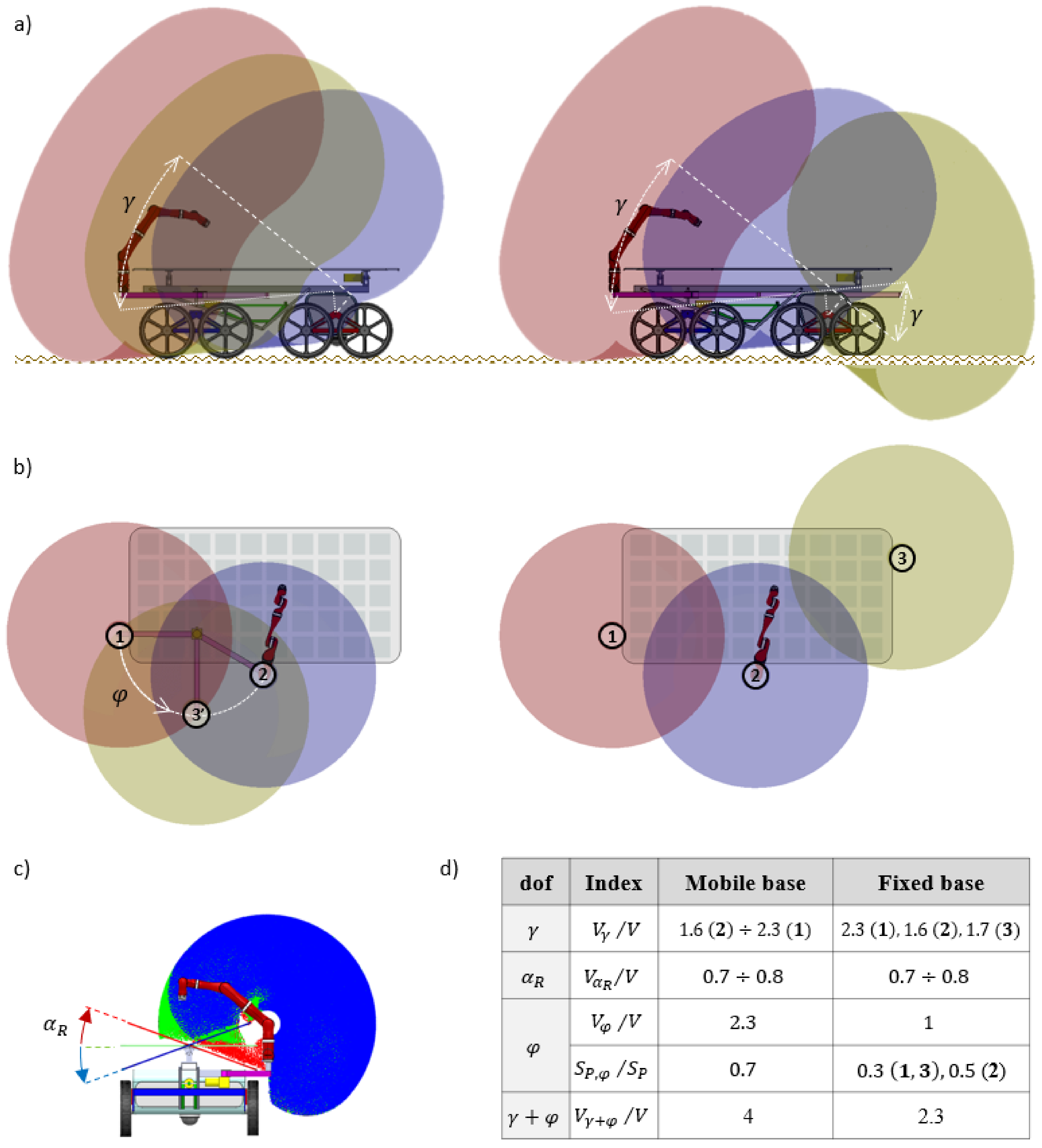
As in [
32], four different indexes are considered, each one associated to a specific degree of freedom of the robotic system (
Figure 9d). The first one is the ratio between the augmented workspace
Vγ related to the pitch angle γ of the rover and the Jaco2 workspace
V. For instance,
Vγ is the workspace potentially available by activating the angle γ, given the position of the robot base with respect to the back chassis.
Figure 9a shows the contribution of γ for the three different positions of the base of the robot. In particular, on the left is depicted the case of rotating beam support, with the robot base in position 1, 2, and 3’, the latter being an intermediate point. Here the ratio
Vγ/V can assume values between 1.6 and 2.3, depending on the
φ angle. Similarly, on the right of
Figure 9a, the solution with fixed mounting point is analyzed. The yellow volume, referred to position 3, demonstrates a great dexterity at the soil level. Because of the fixed positions, in this case the ratio
Vγ/V has discrete values. In the table of
Figure 9d, the numbers in brackets indicate the position related to these values. Concerning the portion of the platform surface
SP that can be covered, the mobile base approach can span a portion
SP,φ by activating the
φ angle. The fixed base approach reaches the maximum value when the arm is mounted in position 2.
Figure 9b shows the comparison of the arm workspace coverage from the top view, for γ = 0. With the mobile support, varying
φ a potential
Vφ/V = 2.3 is obtained. In the case with fixed points this effect is absent, therefore
Vφ/V = 1. However, the Jaco2 can operate on the front side of the platform. This new scenario confers more flexibility to task design.
Figure 9c illustrates the variation of the workspace with three different values of the roll angle α
R. for the critical position 2, which is common for both cases. The roll degree of freedom α
R reduces the workspace of the manipulator and the resulting ratio is 0.7 ≤
VαR/V ≤ 0.8. Finally, the index related to the potential augmented workspace obtained by activating together γ and φ is denoted as
Vγ+φ/V. For the fixed base this index coincides with the maximum value of the ratio
Vγ/V.
To study the influence of the mounting position in practical applications, the solution with fixed points has been chosen for the first Agri.q02 prototype. This will result into a simpler but effective design, which will be used to collect experimental data about the usability of positions 1, 2, and 3. It is important to highlight that with the mobile support the robot can be moved seamlessly from one configuration to another while the robotic system is working. This flexibility is not possible with the three mounting positions; in this case it is necessary to choose the base position before the rover starts moving. Therefore, the solution adopted in the physical prototype permits to obtain good results in terms of augmented robotic workspace and surface platform covered by the robot, but it is more rigid than the solution with the mobile support.
6. Electronic Integration
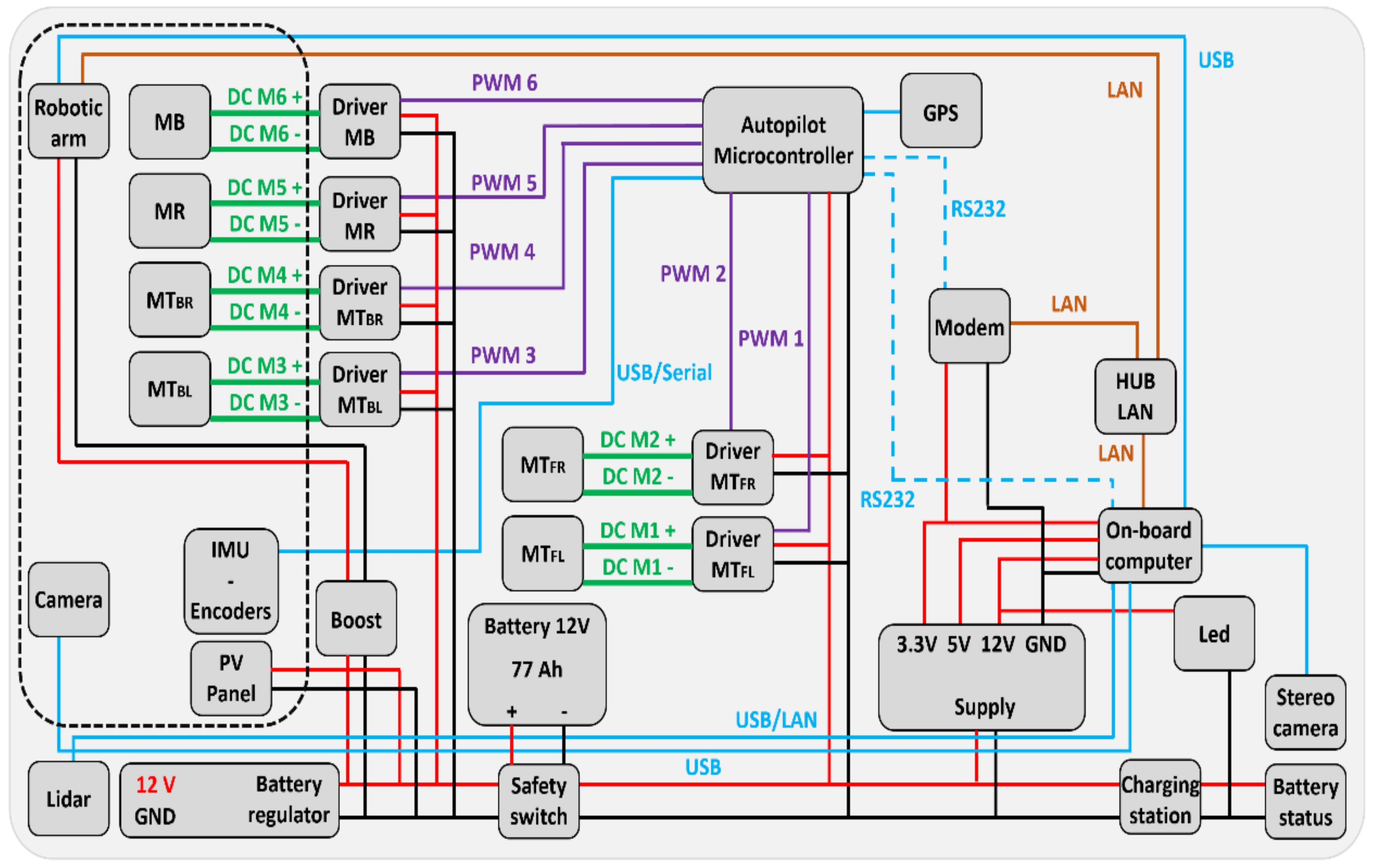
In
Figure 10 a scheme of the electrical and electronic components of the robotic system Agri.q02 is presented. The components that are on the rear side of the Agri.q02 or on the photovoltaic panels are the ones inside the dashed rectangle. Instead, the elements outside this rectangle are mounted on the front side of the rover. The power to the robotic arm, to the actuators, to the control devices, and to the sensors is supplied by a 56 Ah, 24 V battery.
A battery regulator connects the 12 V battery to the PV panels, handling the charging cycle. The robotic arm works at the average power of 25 W [
27] and requires a power supply voltage between 18 V and 29 V; for this reason, a voltage booster connects the battery to the manipulator in order to raise the voltage from 12 V to the desired level. To actuate the driving units MT, four DC motors with a nominal power of 120 W and 24 V supply voltage have been selected; for the pitch angle, the linear actuator MB generates up to 100 W power, while the roll angle is activated through MR by a 30 W motor. The stored energy of the battery is 4.84 MJ; with the hypothesis of the average consumption of 150 W the rover can be autonomous of 9 h without the use of the solar panels.
The sensors placed on the rover are: encoders of the motors, frontal and rear stereo cameras useful to obtain a full view of the working environment, a lidar, mounted under the rover to inspect the ground, and an IMU used to check the attitude of the rear part of the Agri.q02 with respect to the front one. An additional camera could be mounted on the robotic arm in order to have more information that could be useful in several tasks. The data from the sensors are gathered, analyzed, and memorized by an on-board computer, which calculates also the set values for the motor drivers.
Two different operative modalities are possible: (1) robotic system remotely controlled by an operator; (2) self-guidance state modality. Regarding the first modality, a modem makes possible the communications between the system and the operator, who can move properly the robotic system owing to the information supplied by the cameras and the lidar.
An autopilot microcontroller manages the self-guidance state modality. The attitude of the rover is checked by the autopilot microcontroller through its own sensors, which are a GPS receiver, a barometer, a compass, accelerometers and gyroscopes. To use the data acquired by the sensors, the autopilot controller communicates with the on-board computer. The autopilot microcontroller has also a charge sensor to control the charge of the battery.
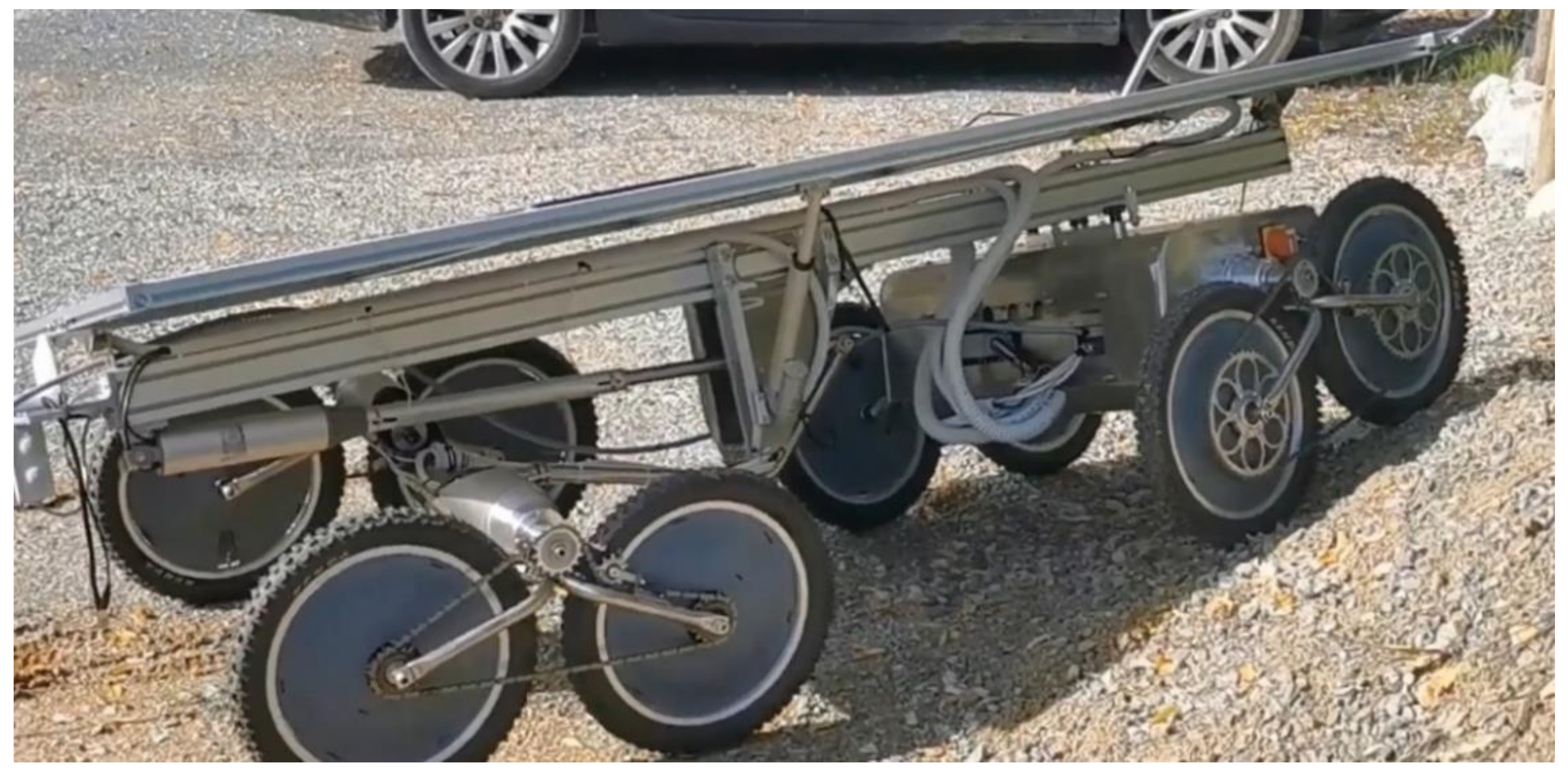
7. Physical Prototype
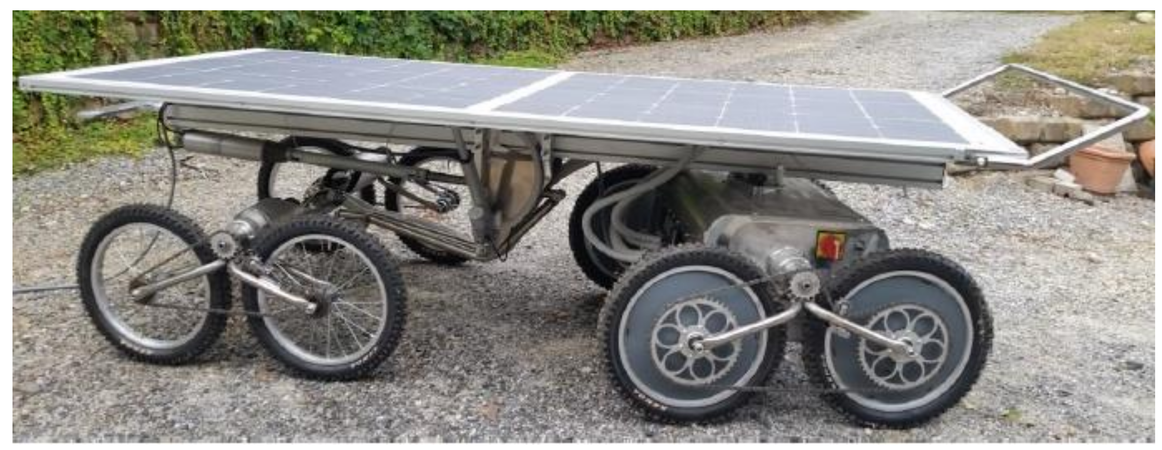
The Agri.q02 prototype is shown in
Figure 11. Despite the complexity of the rover kinematics, the robot consists of basic commercial mechanical components. The main structure is built of aluminum, with steel elements in the areas of stress concentration of the driving units and the position mechanism. The wheels are off-road bike type with a radius of 200 mm. The solar panel is composed of three modules with a total area approximately of 2 m
2 and with a maximum output power of 360 W.
There are few differences between the functional design of Agri.q02 and the physical prototype. The roll angle αR is here controlled by a linear actuator instead of a revolute one, as supposed in the design phase. This linear actuator permits to obtain a more robust solution with respect to that achievable with the revolute actuator. Moreover, a tubular bumper has been mounted on the front edge of the platform chassis: in case of collision with a frontal obstacle, the bumper rotates in the pitch plane and activates the brakes of the rover actuators by means of a position sensor, the latter mounted on the hinges that connect the tube to the platform.
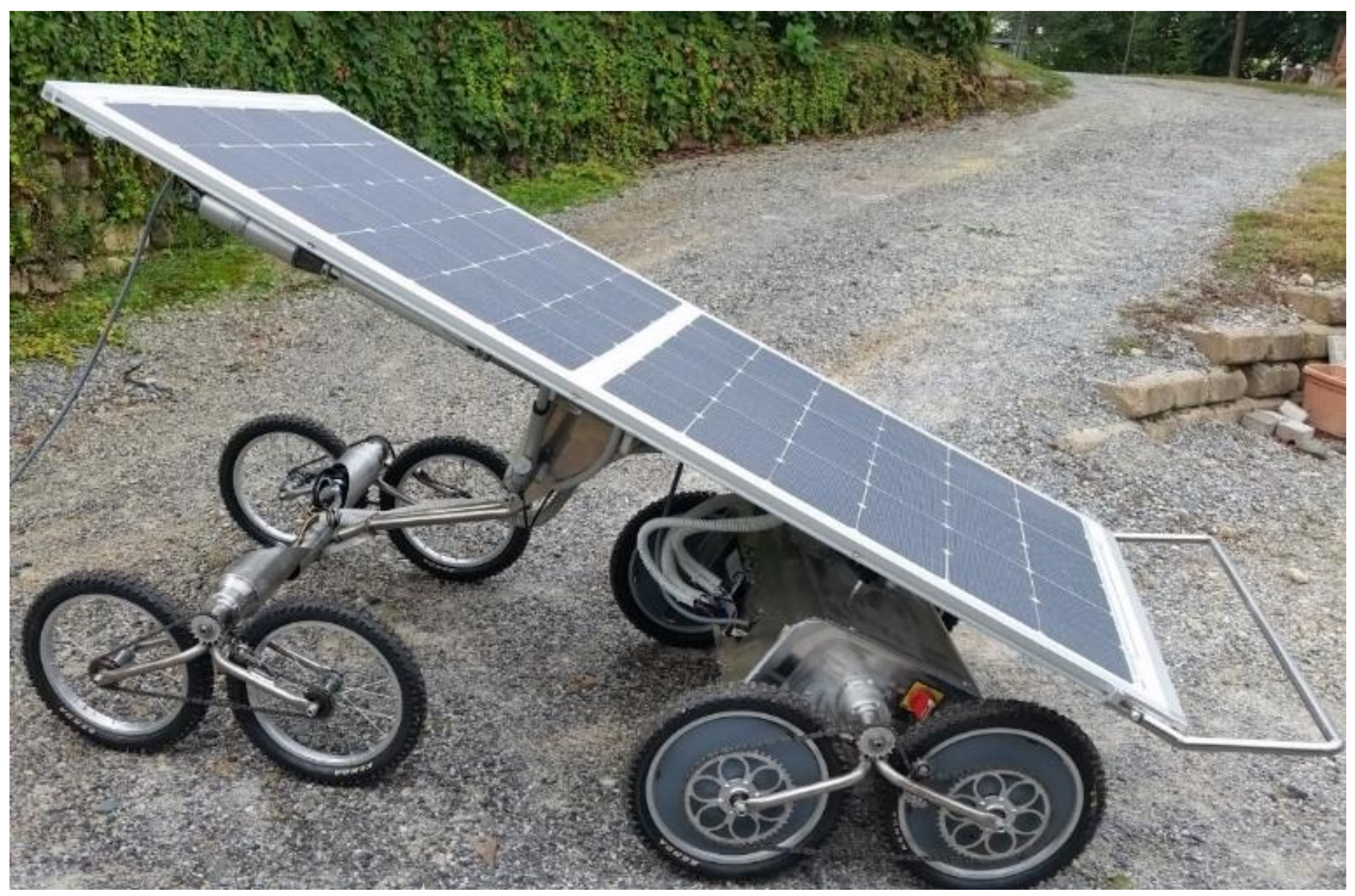
The prototype has the motion capabilities illustrated in
Section 3. The ball screw linear actuator permits to turn the platform at the desired pitch angle γ so to keep the platform horizontal or, as in
Figure 12, to collect sunlight effectively. Moreover, the rover is able to move on an irregular soil keeping all the wheels in contact with the terrain, owing to the passive joint F and to the rocker arms on which the wheels are mounted (
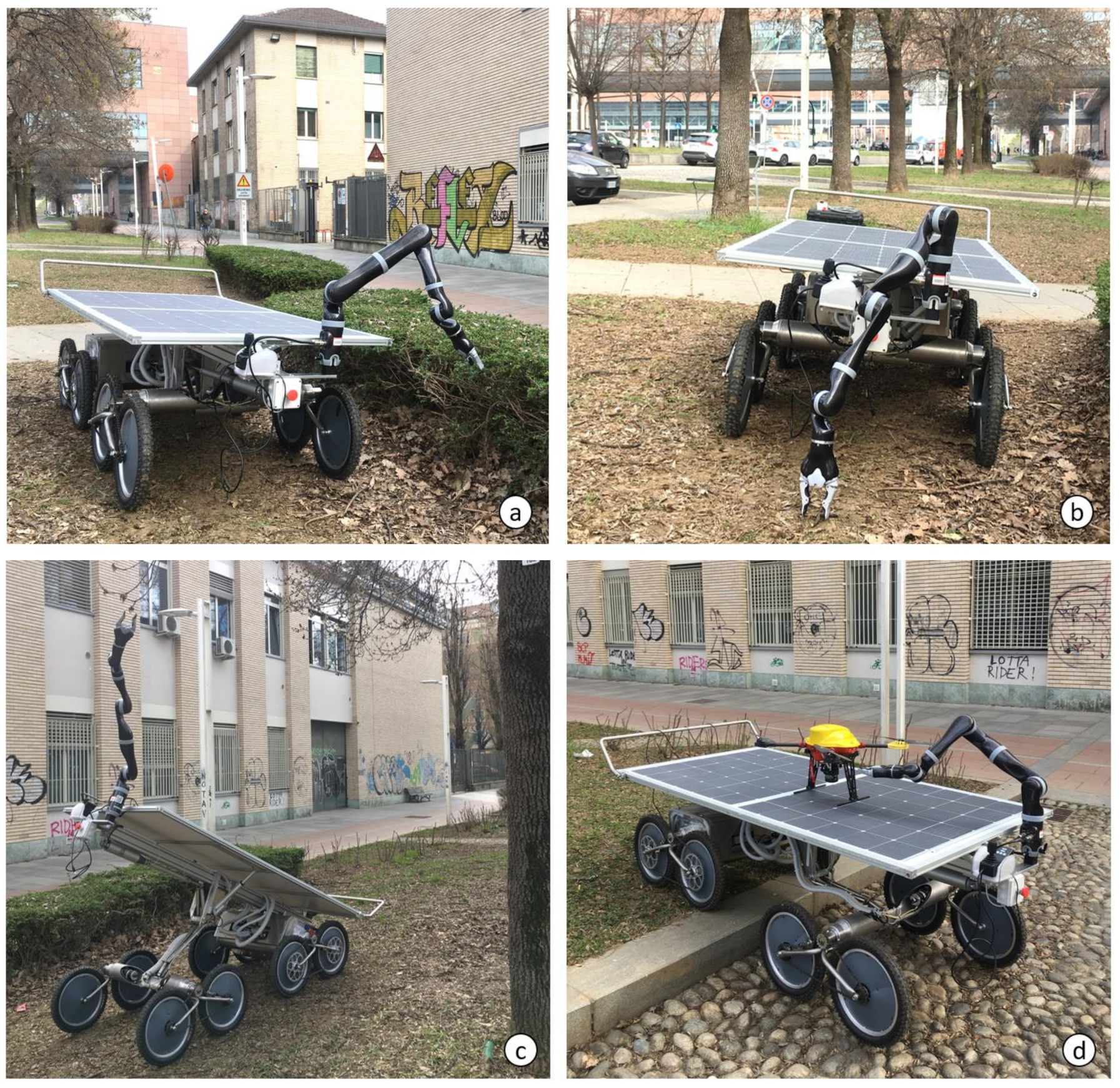
Figure 13). Finally,
Figure 14 shows Agri.q02 in four different possible scenarios, with the robotic arm mounted in position 1. In
Figure 14a the manipulator works on the side of the rover and in
Figure 14b it reaches the ground. If the pitch angle is activated (
Figure 14c) the arm can grasp samples up to 2 m from the ground. In presence of steps and slopes, the pitch and roll angle can be arranged to keep the platform horizontal and to allow the drone to land safely, in order to receive samples or to be assisted by the robotic arm (
Figure 14d).

 ,
, 


