Towards Tethered Tool Manipulation Planning with the Help of a Tool Balancer †


Abstract
1. Introduction
1.1. Motion Planning
1.2. Manipulation Planning
1.3. Contribution
2. Materials and Methods
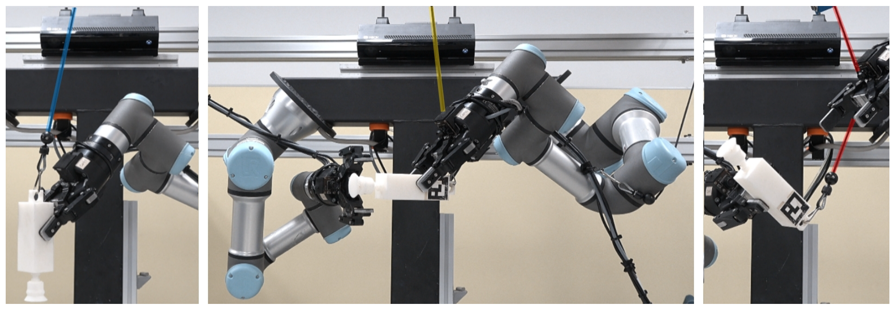
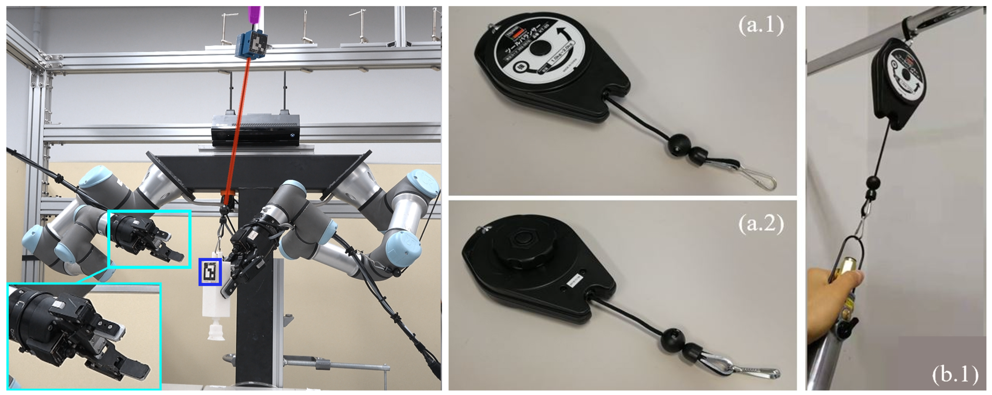
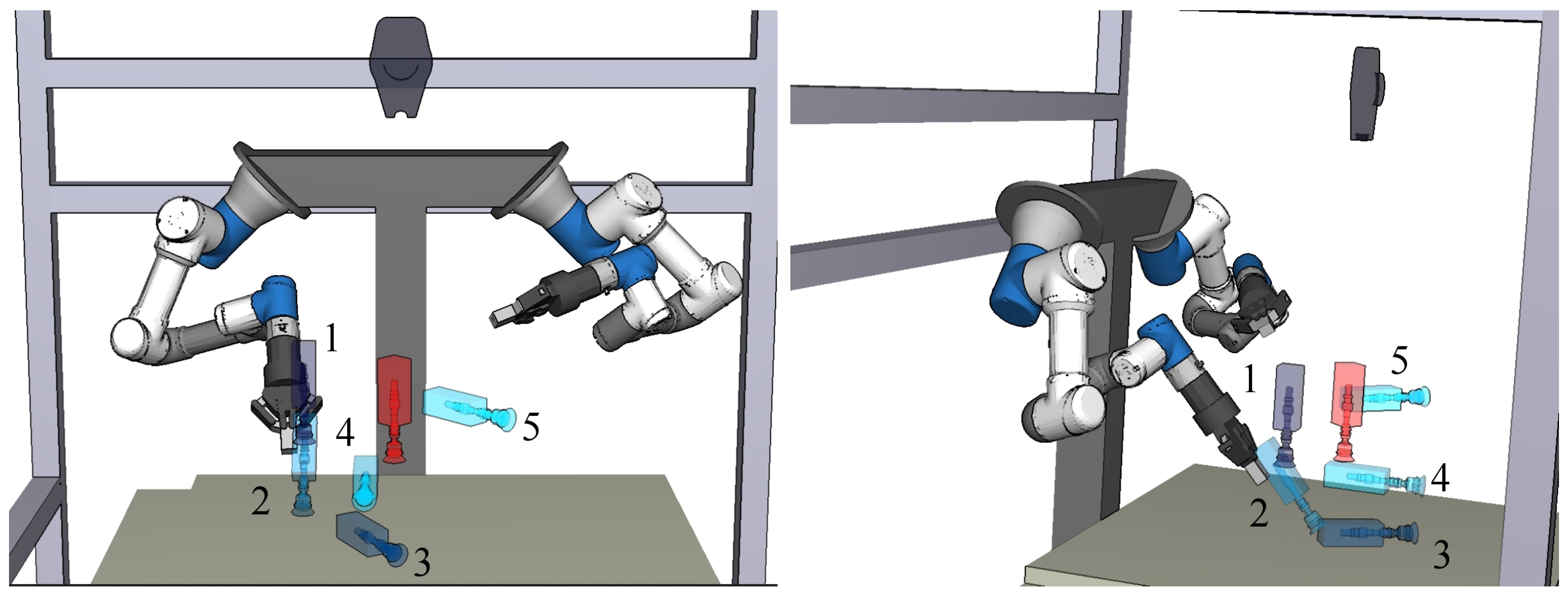
2.1. Real-world Setting
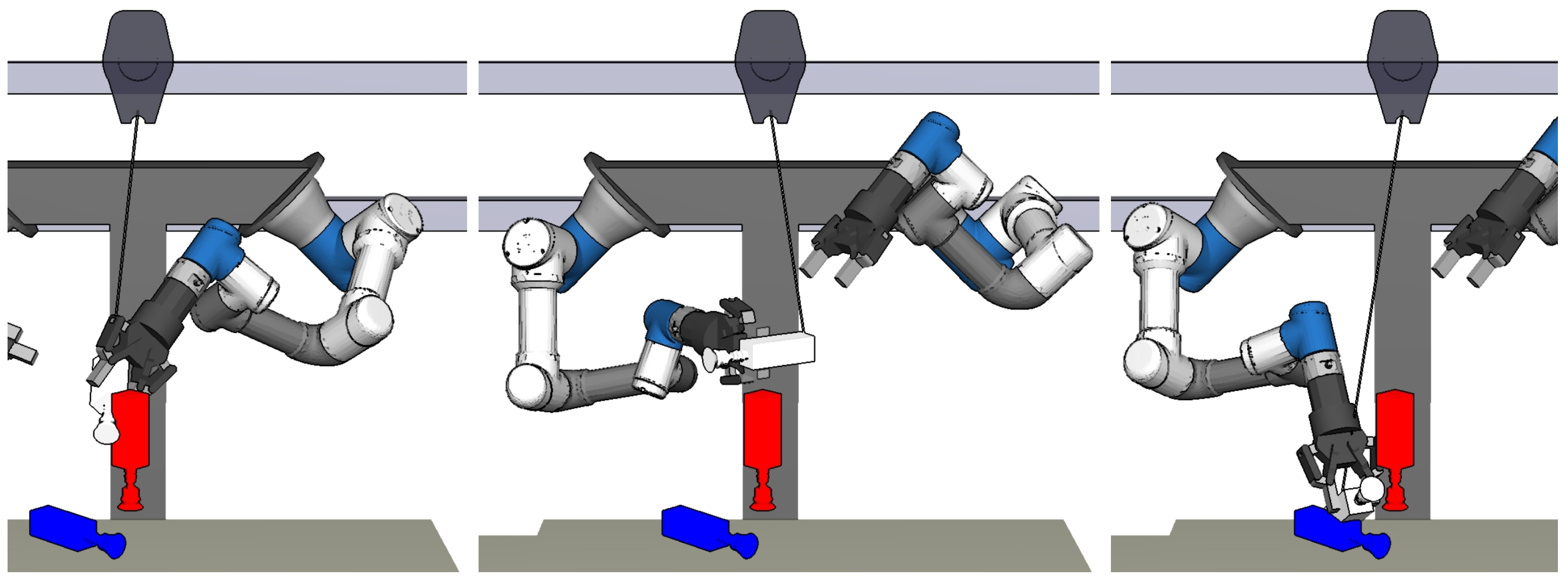
2.2. Simulation Setting
2.3. Manipulation Planner
3. Constraints for Entanglement Avoidance
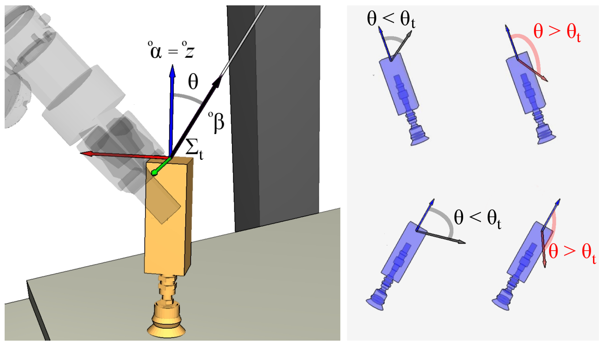
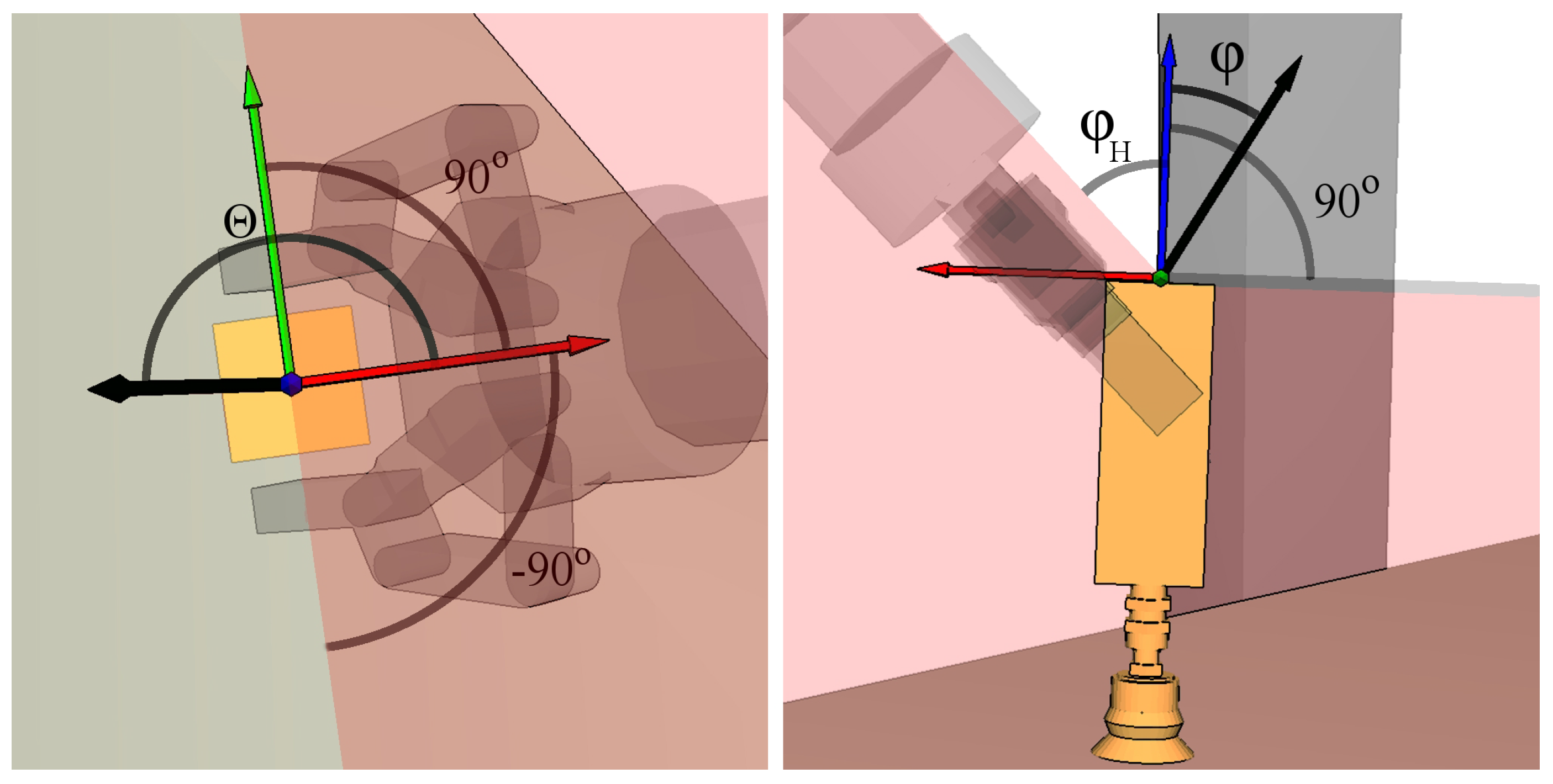
3.1. Orientation Constraints
3.1.1. Computation of the Bending Angles
3.1.2. Angular Measurement of Cable Bending
3.2. Angle Accumulation Constraints
Angle Accumulation Constraints in Sampling-based Motion Planning
4. Experiments
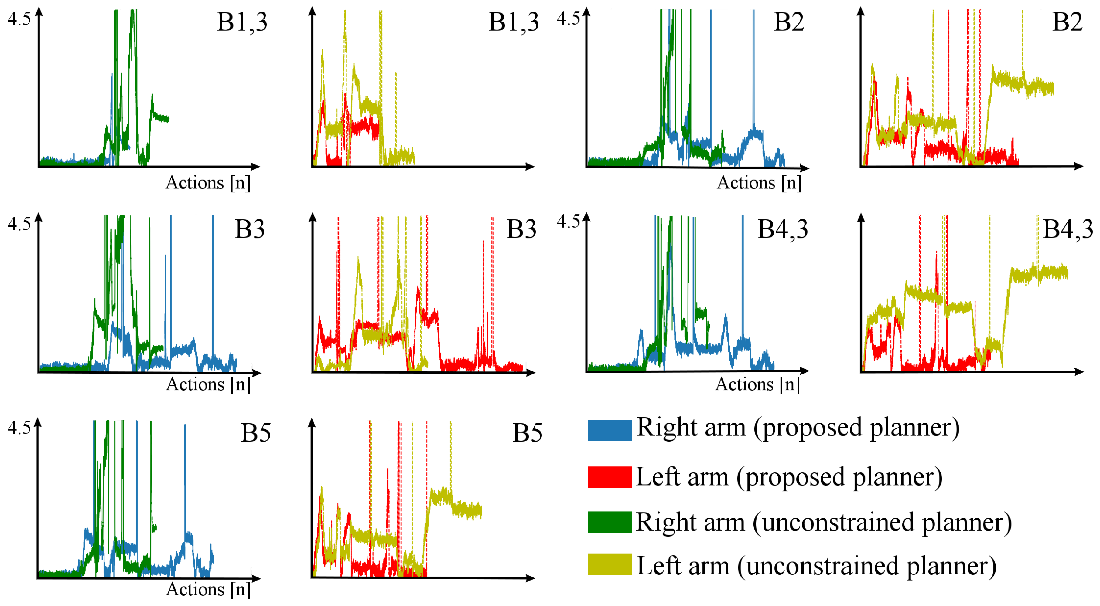
4.1. Simulations
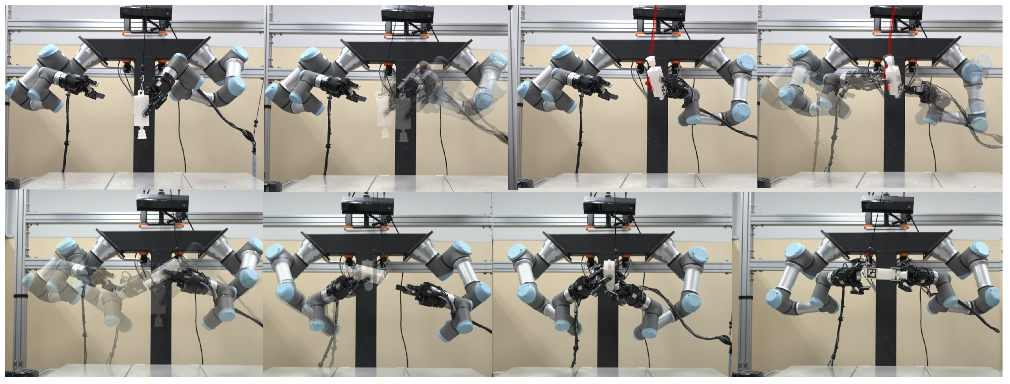
4.2. Real-world Experiments
5. Discussion
Author Contributions
Funding
Conflicts of Interest
References
- Lozano-Pérez, T.; Wesley, M.A. An algorithm for planning collision-free paths among polyhedral obstacles. Commun. ACM 1979, 22, 560–570. [Google Scholar] [CrossRef]
- Canny, J.; Reif, J. New lower bound techniques for robot motion planning problems. In Proceedings of the 28th Annual Symposium on Foundations of Computer Science (sfcs 1987), Los Angeles, CA, USA, 12–14 October 1987; pp. 49–60. [Google Scholar]
- Shibata, T.; Fukuda, T. Intelligent motion planning by genetic algorithm with fuzzy critic. In Proceedings of the 8th IEEE International Symposium on Intelligent Control, Chicago, IL, USA, 25–27 August 1993; pp. 565–570. [Google Scholar]
- Vachtsevanos, G.; Hexmoor, H. A fuzzy logic approach to robotic path planning with obstacle avoidance. In Proceedings of the 25th IEEE Conference on Decision and Control, Athens, Greece, 10–12 December 1986; pp. 1262–1264. [Google Scholar]
- Zacksenhouse, M.; DeFigueiredo, R.J.; Johnson, D.H. A neural network architecture for cue-based motion planning. In Proceedings of the 27th IEEE Conference on Decision and Control, Austin, TX, USA, 7–9 December 1988; pp. 324–327. [Google Scholar]
- Janglová, D. Neural networks in mobile robot motion. Int. J. Adv. Robot. Syst. 2004, 1, 2. [Google Scholar] [CrossRef]
- Sugihara, K.; Smith, J. Genetic algorithms for adaptive motion planning of an autonomous mobile robot. In Proceedings of the the 1997 IEEE International Symposium on Computational Intelligence in Robotics and Automation CIRA’97.’Towards New Computational Principles for Robotics and Automation’, Monterey, CA, USA, 10–11 July 1997; pp. 138–143. [Google Scholar]
- Gen, M.; Cheng, R.; Wang, D. Genetic algorithms for solving shortest path problems. In Proceedings of the 1997 IEEE International Conference on Evolutionary Computation (ICEC’97), Indianapolis, IN, USA, 13–16 April 1997; pp. 401–406. [Google Scholar]
- Chen, M.; Zalzala, A.M. A genetic approach to motion planning of redundant mobile manipulator systems considering safety and configuration. J. Robot. Syst. 1997, 14, 529–544. [Google Scholar] [CrossRef]
- Pfeiffer, M.; Schaeuble, M.; Nieto, J.; Siegwart, R.; Cadena, C. From perception to decision: A data-driven approach to end-to-end motion planning for autonomous ground robots. In Proceedings of the 2017 IEEE international conference on robotics and automation (icra), Marina Bay Sands, Singapore, 29 May–3 June 2017; pp. 1527–1533. [Google Scholar]
- Ye, G.; Alterovitz, R. Guided motion planning. In Robotics Research; Springer: Berlin, Germany, 2017; pp. 291–307. [Google Scholar]
- Murray, S.; Floyd-Jones, W.; Qi, Y.; Sorin, D.J.; Konidaris, G. Robot Motion Planning on a Chip. In Proceedings of the Robotics: Science and Systems, Ann Arbor, MI, USA, 18–22 June 2016. [Google Scholar]
- Tournassoud, P.; Lozano-Pérez, T.; Mazer, E. Regrasping. In Proceedings of the 1987 IEEE International Conference on Robotics and Automation, Raleigh, NC, USA, 31 March–3 April 1987; pp. 1924–1928. [Google Scholar]
- Stoeter, S.A.; Voss, S.; Papanikolopoulos, N.P.; Mosemann, H. Planning of regrasp operations. In Proceedings of the 1999 IEEE International Conference on Robotics and Automation, Detroit, MI, USA, 10–15 May 1999; pp. 245–250. [Google Scholar]
- Lozano-Pérez, T.; Jones, J.L.; O’Donnell, P.A.; Mazer, E. Handey: A Robot Task Planner; MIT Press: Cambridge, MA, USA, 1992. [Google Scholar]
- Wan, W.; Harada, K. Developing and comparing single-arm and dual-arm regrasp. IEEE Robot. Autom. Lett. 2016, 1, 243–250. [Google Scholar] [CrossRef]
- Calandra, R.; Owens, A.; Jayaraman, D.; Lin, J.; Yuan, W.; Malik, J.; Adelson, E.H.; Levine, S. More Than a Feeling: Learning to Grasp and Regrasp using Vision and Touch. IEEE Robot. Autom. Lett. 2018, 3, 3300–3307. [Google Scholar] [CrossRef]
- Wan, W.; Harada, K. Reorientating objects with a gripping hand and a table surface. In Proceedings of the 2015 IEEE-RAS 15th International Conference on Humanoid Robots (Humanoids), Seoul, Korea, 3–5 November 2015; pp. 101–106. [Google Scholar]
- La Mura, F.; Todeschini, G.; Giberti, H. High performance motion-planner architecture for hardware-in-the-loop system based on position-based-admittance-control. Robotics 2018, 7, 8. [Google Scholar] [CrossRef]
- Dogar, M.; Spielberg, A.; Baker, S.; Rus, D. Multi-robot grasp planning for sequential assembly operations. Auton. Robot. 2019, 43, 649–664. [Google Scholar] [CrossRef]
- Hou, Y.; Jia, Z.; Mason, M.T. Fast Planning for 3D Any-Pose-Reorienting Using Pivoting. In Proceedings of the 2018 IEEE International Conference on Robotics and Automation (ICRA), Brisbane, Australia, 21–25 May 2018; pp. 1631–1638. [Google Scholar]
- Hert, S.; Lumelsky, V. The ties that bind: Motion planning for multiple tethered robots. Auton. Robot. 1996, 17, 187–215. [Google Scholar] [CrossRef]
- Igarashi, T.; Stilman, M. Homotopic path planning on manifolds for cabled mobile robots. In Algorithmic Foundations of Robotics IX; Springer: Berlin, Germany, 2010; pp. 1–18. [Google Scholar]
- Bretl, T.; McCarthy, Z. Quasi-static manipulation of a Kirchhoff elastic rod based on a geometric analysis of equilibrium configurations. Int. J. Robot. Res. 2014, 33, 48–68. [Google Scholar] [CrossRef]
- Ramirez-Alpizar, I.G.; Naveau, M.; Benazeth, C.; Stasse, O.; Laumond, J.P.; Harada, K.; Yoshida, E. Motion generation for pulling a fire hose by a humanoid robot. In Proceedings of the 2016 IEEE-RAS 16th International Conference on Humanoid Robots (Humanoids), Cancun, Mexico, 15–17 November 2016; pp. 1016–1021. [Google Scholar]
- Zhu, J.; Navarro, B.; Fraisse, P.; Crosnier, A.; Cherubini, A. Dual-arm robotic manipulation of flexible cables. In Proceedings of the IROS: International Conference on Intelligent Robots and Systems, Madrid, Spain, 1–5 October 2018. [Google Scholar]
- Saha, M.; Isto, P. Motion planning for robotic manipulation of deformable linear objects. In Proceedings of the 2006 IEEE International Conference on Robotics and Automation, Orlando, FL, USA, 15–19 May 2006; pp. 2478–2484. [Google Scholar]
- Khalil, F.F.; Payeur, P. Dexterous robotic manipulation of deformable objects with multi-sensory feedback-a review. In Robot Manipulators Trends and Development; InTechOpen: London, UK, 2010. [Google Scholar]
- Sánchez, D.; Wan, W.; Harada, K. Arm manipulation planning of tethered tools with the help of a tool balancer. In IFToMM World Congress on Mechanism and Machine Science; Springer: Berlin, Germany, 2019; pp. 2567–2576. [Google Scholar]
- Raessa, M.; Sánchez, D.; Wan, W.; Petit, D.; Harada, K. Teaching a robot to use electric tools with regrasp planning. CAAI Trans. Intell. Technol. 2019, 4, 54–63. [Google Scholar] [CrossRef]
- Sanchez, D.; Wan, W.; Harada, K. Tethered Tool Manipulation Planning with Cable Maneuvering. arXiv 2019, arXiv:1909.10686. [Google Scholar] [CrossRef]


| Benchmark | Proposed Planner | Unconstrained Planner | ||
|---|---|---|---|---|
| 1 | ||||
| 2 | ||||
| 3 | ||||
| 4 | ||||
| 5 | ||||
| 5,2 | ⨂ | |||
| 1,3 | ||||
| 4,3 |
| Benchmark | Proposed Planner | Unconstrained Planner | ||
|---|---|---|---|---|
| 1,3 | ∘ | ⊘ | ||
| 2 | ∘ | ⊘ | ||
| 3 | ∘ | ∘ | ||
| 4,3 | ∘ | ⊘ | ||
| 5 | ∘ | ⊘ |
© 2020 by the authors. Licensee MDPI, Basel, Switzerland. This article is an open access article distributed under the terms and conditions of the Creative Commons Attribution (CC BY) license (http://creativecommons.org/licenses/by/4.0/).
Share and Cite
Sanchez, D.; Wan, W.; Harada, K. Towards Tethered Tool Manipulation Planning with the Help of a Tool Balancer. Robotics 2020, 9, 11. https://doi.org/10.3390/robotics9010011
Sanchez D, Wan W, Harada K. Towards Tethered Tool Manipulation Planning with the Help of a Tool Balancer. Robotics. 2020; 9(1):11. https://doi.org/10.3390/robotics9010011
Chicago/Turabian StyleSanchez, Daniel, Weiwei Wan, and Kensuke Harada. 2020. "Towards Tethered Tool Manipulation Planning with the Help of a Tool Balancer" Robotics 9, no. 1: 11. https://doi.org/10.3390/robotics9010011
APA StyleSanchez, D., Wan, W., & Harada, K. (2020). Towards Tethered Tool Manipulation Planning with the Help of a Tool Balancer. Robotics, 9(1), 11. https://doi.org/10.3390/robotics9010011