Design and Implementation of a Quadruped Amphibious Robot Using Duck Feet


Abstract
:1. Introduction
2. Literature Review
3. Design and Methodology
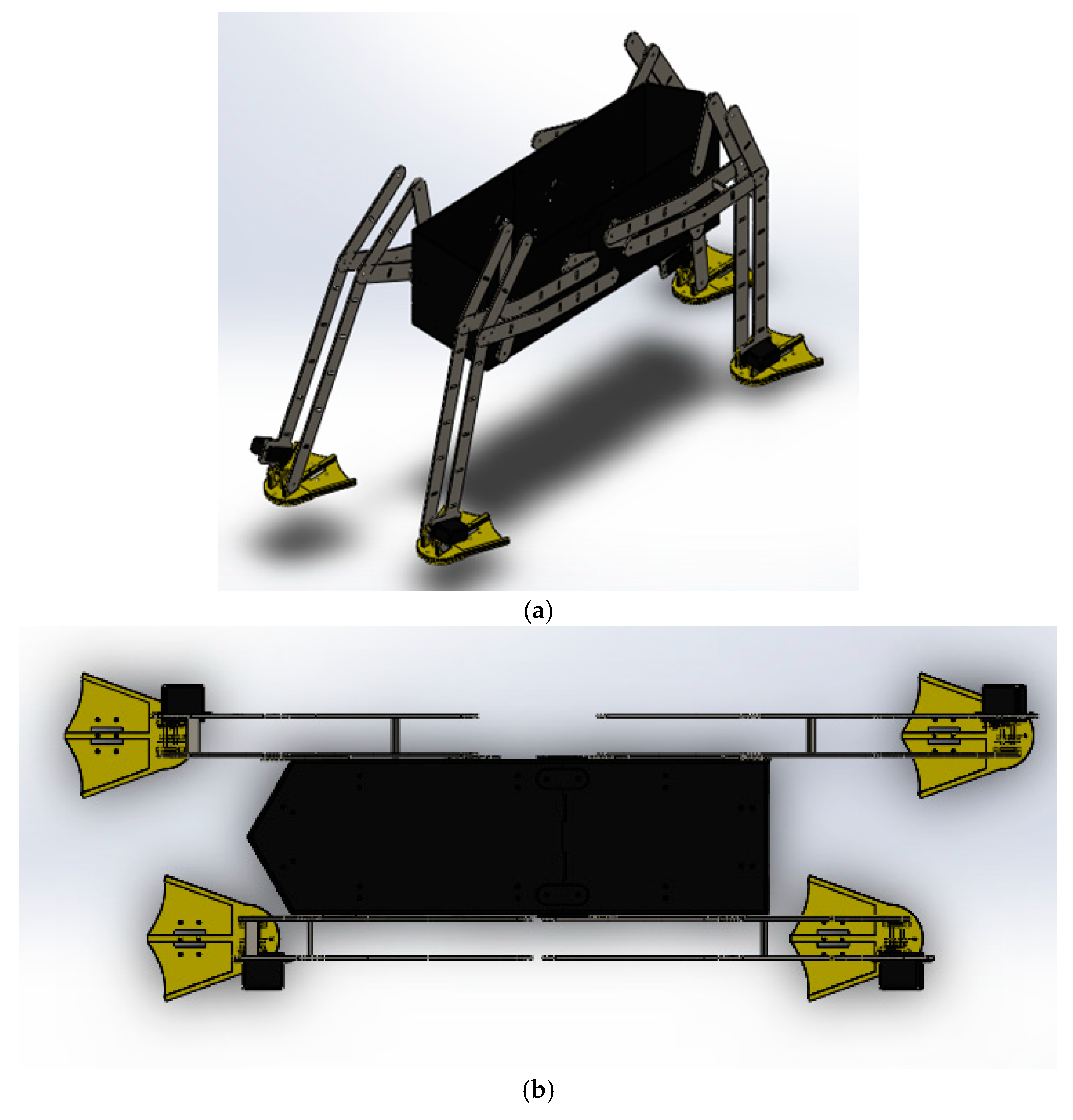
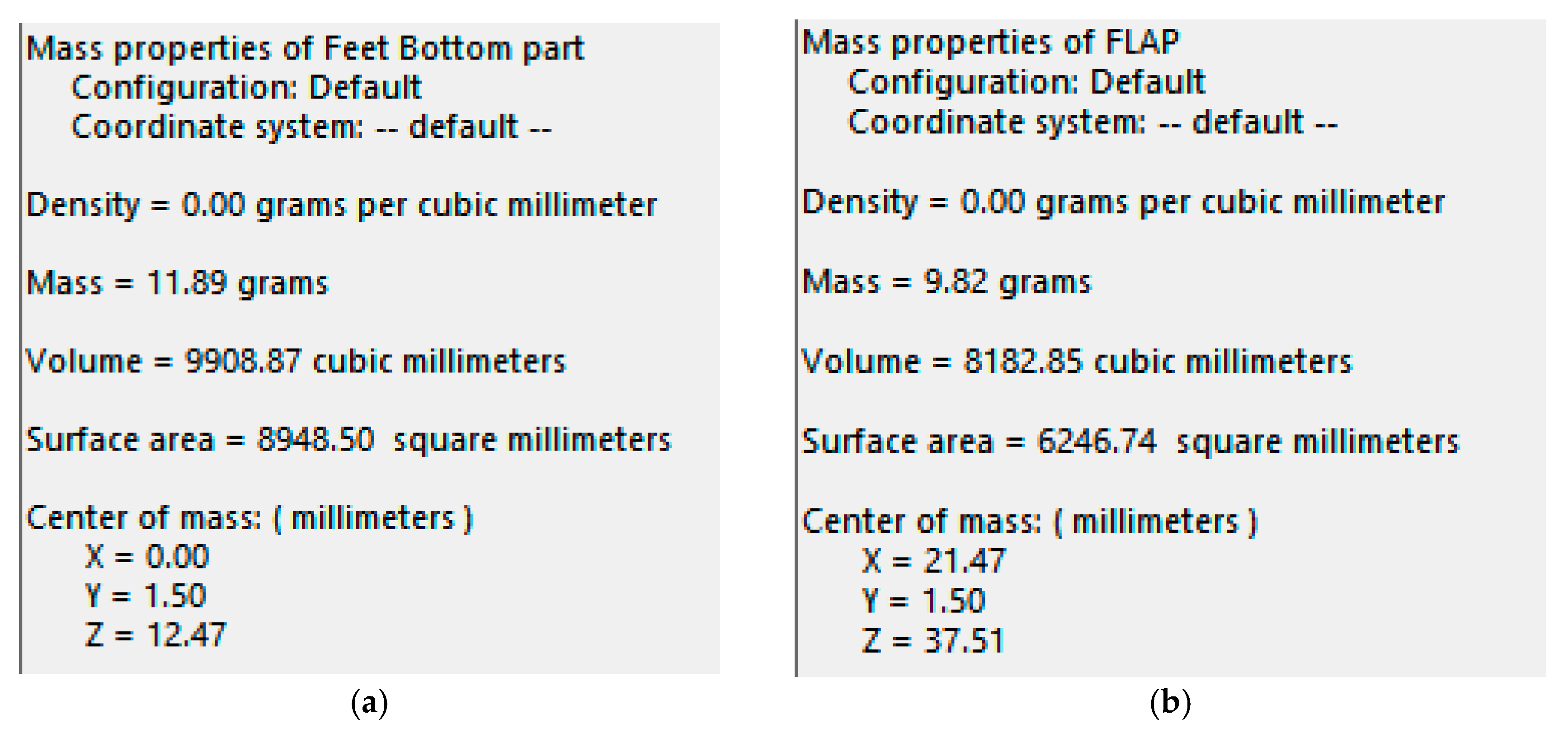
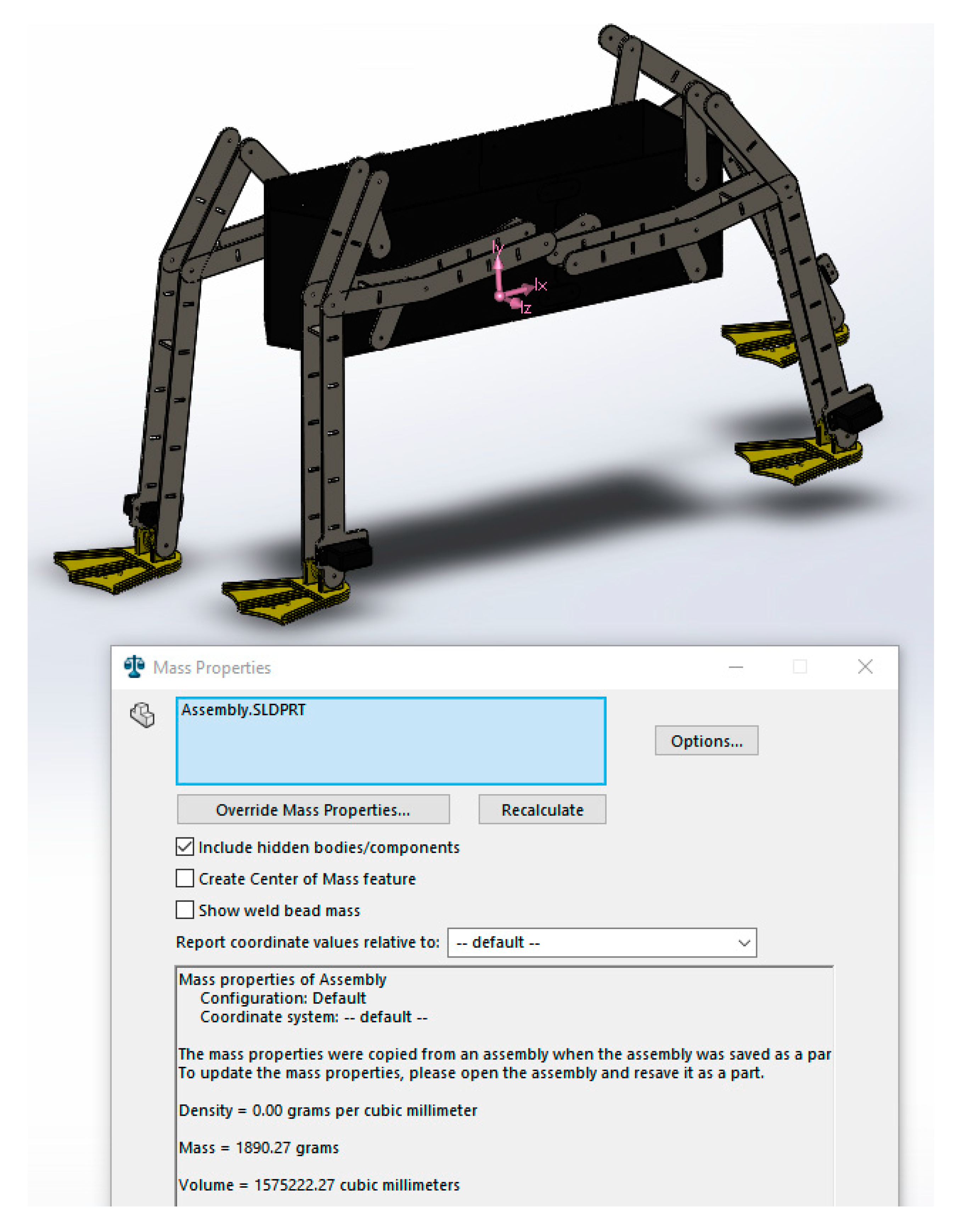
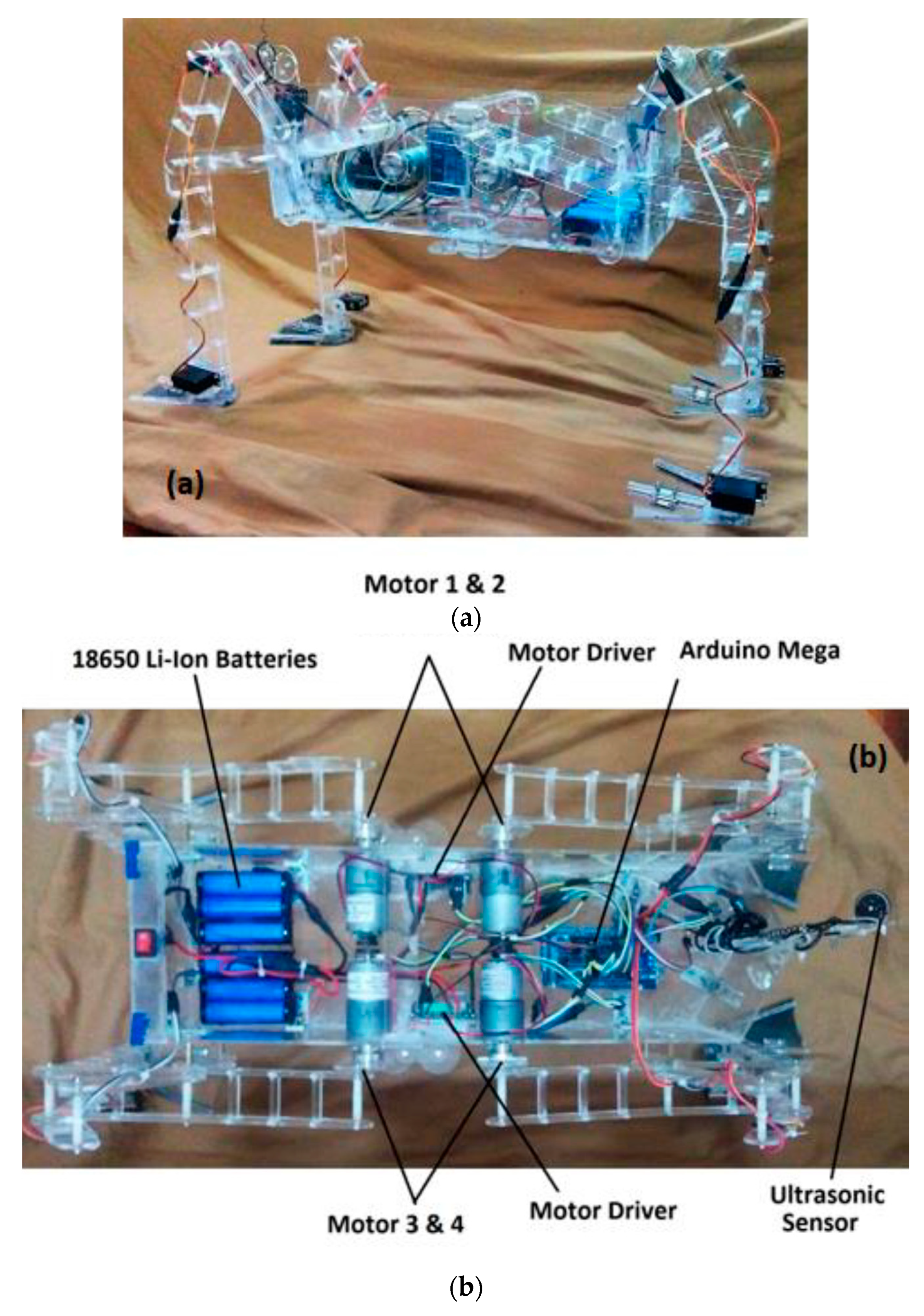
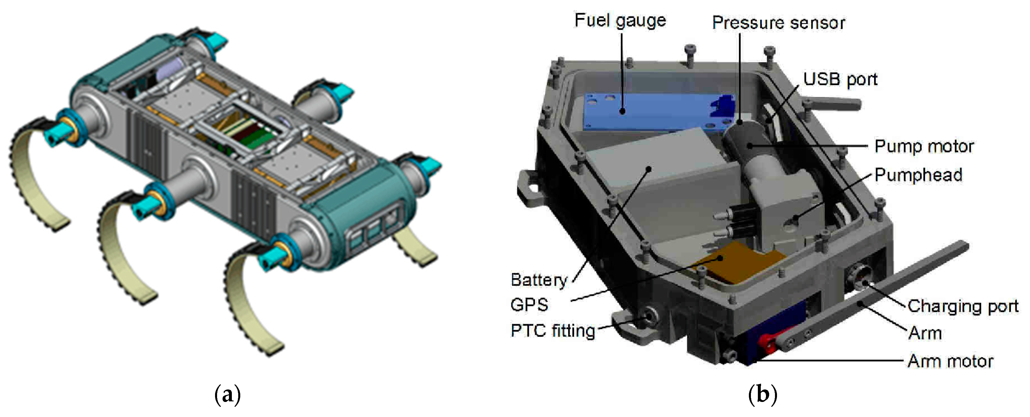
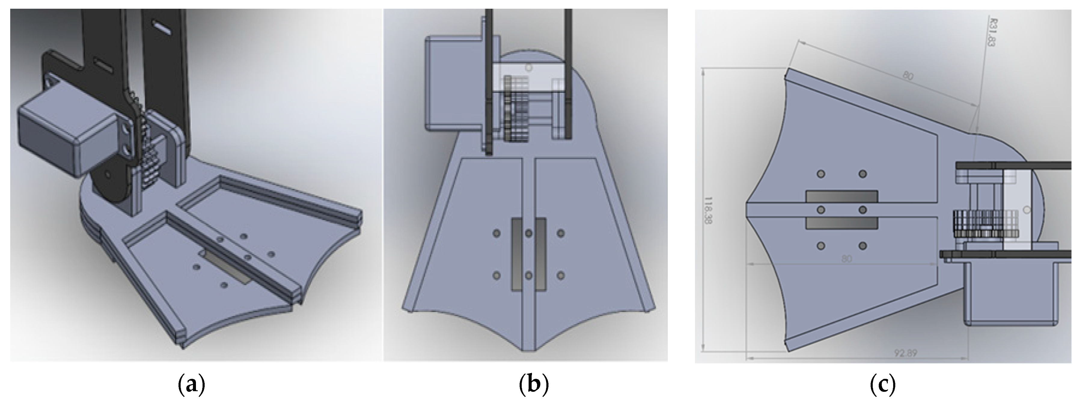
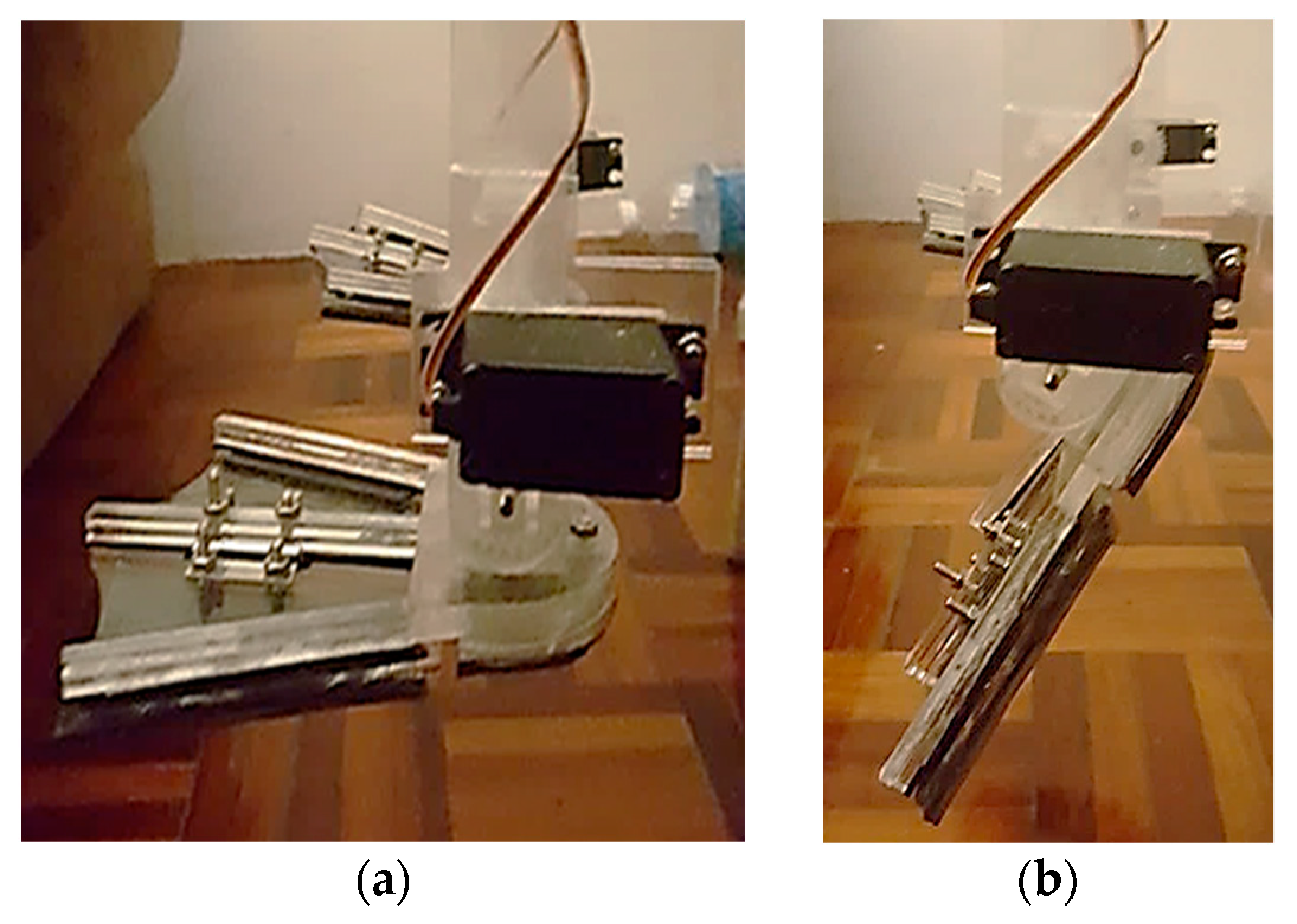
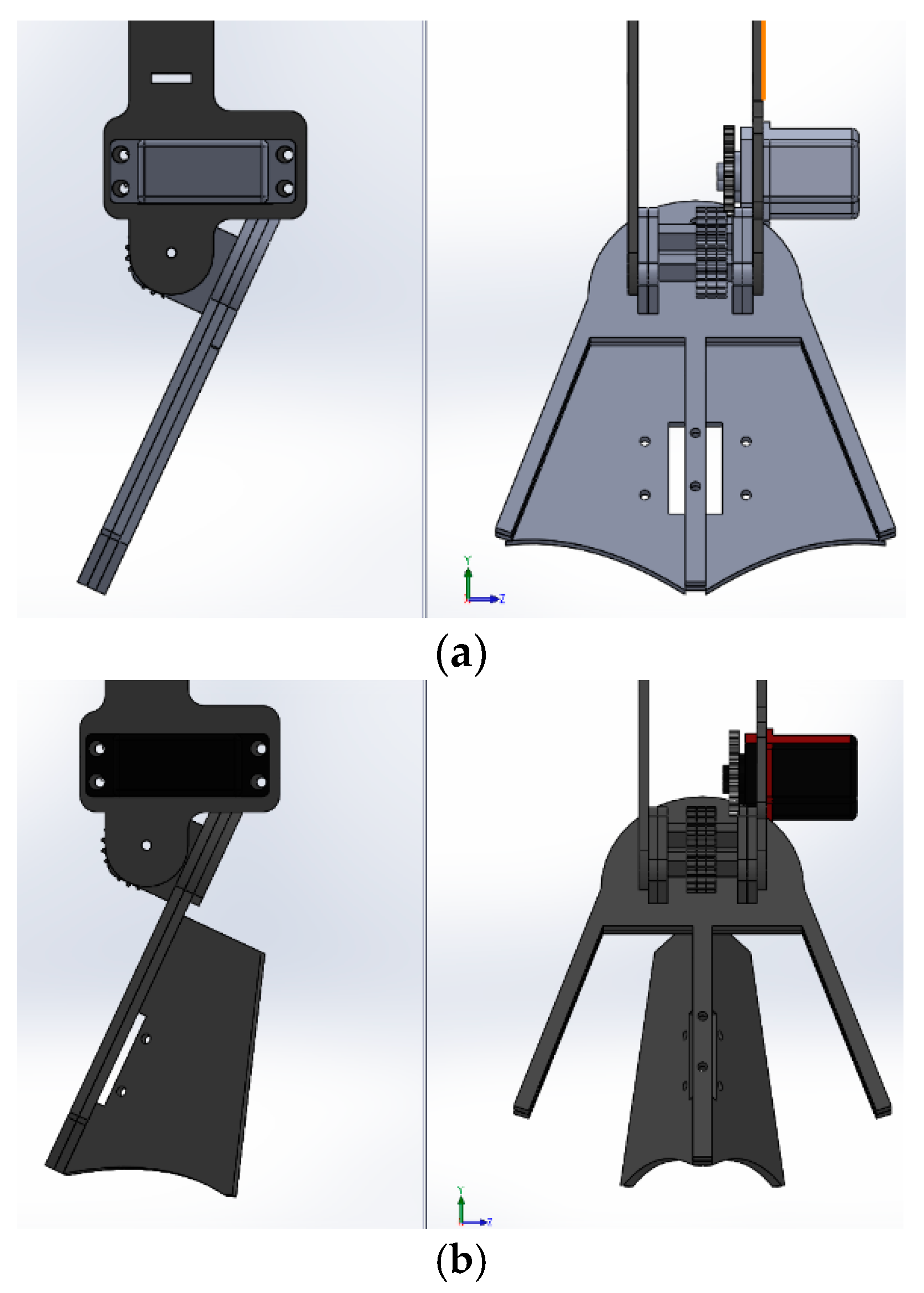
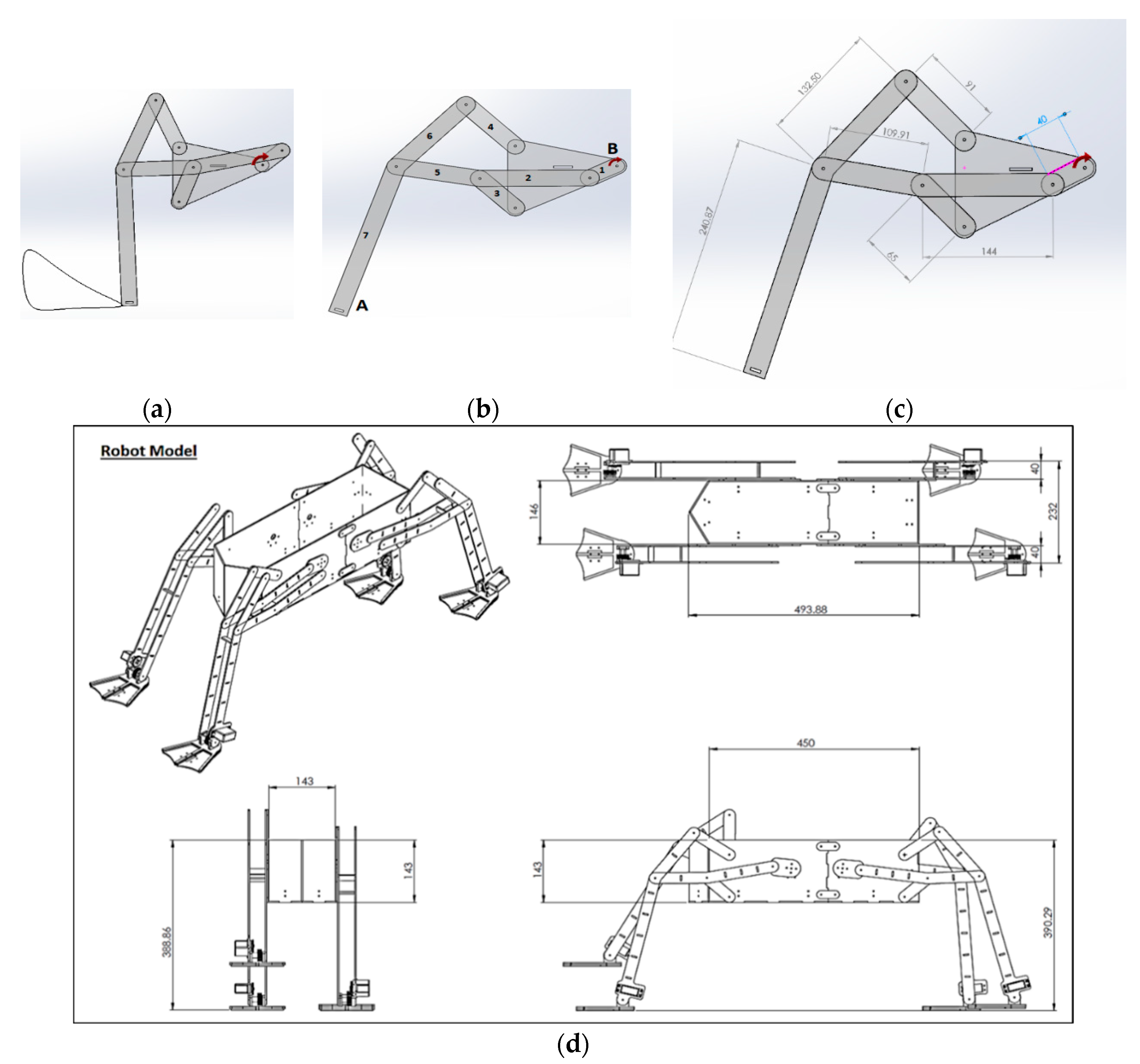
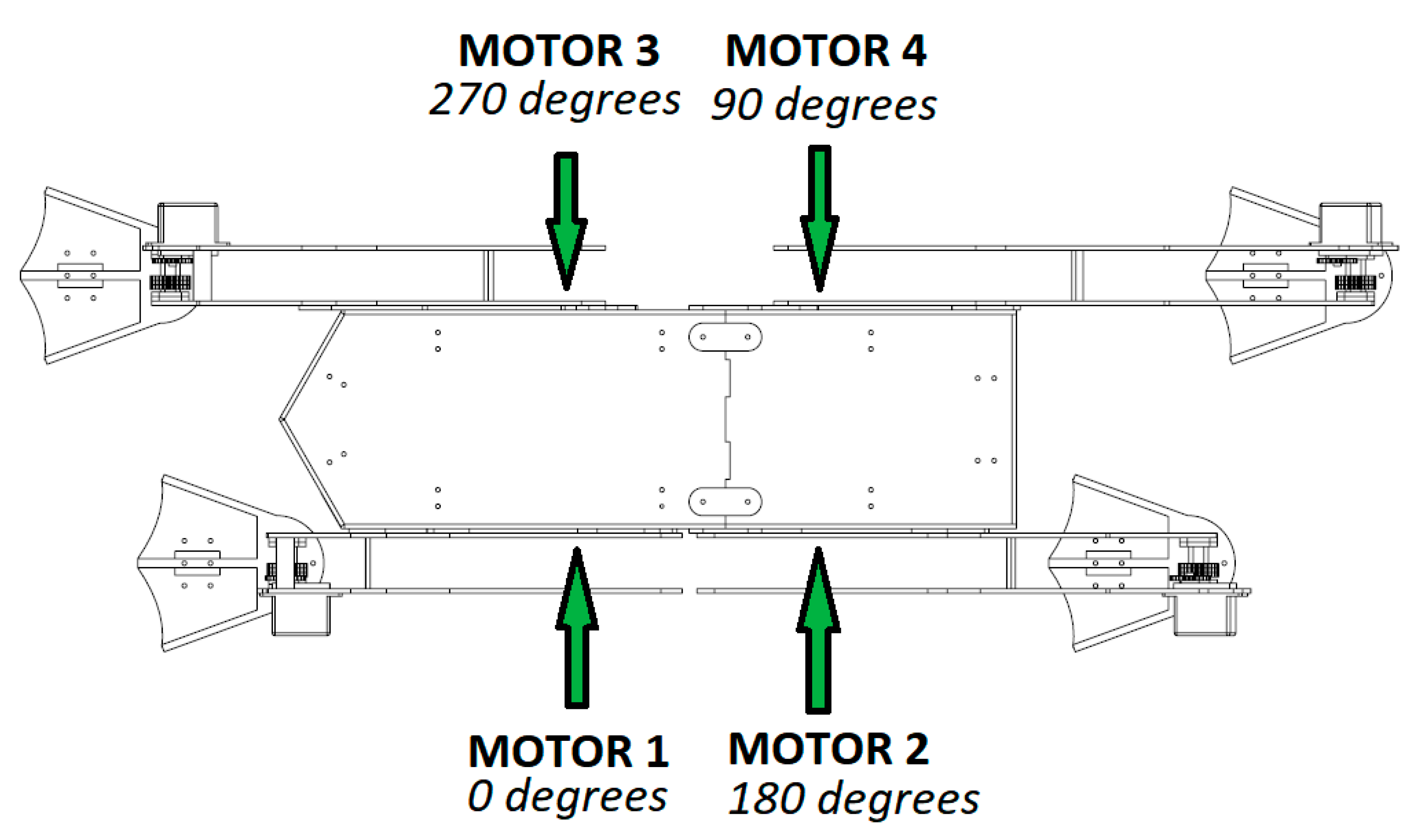
3.1. Mechanical Design
- -
- is the density of the fluid;
- -
- v is the velocity of the object;
- -
- CD is the drag coefficient; and
- -
- A is the area of the object.
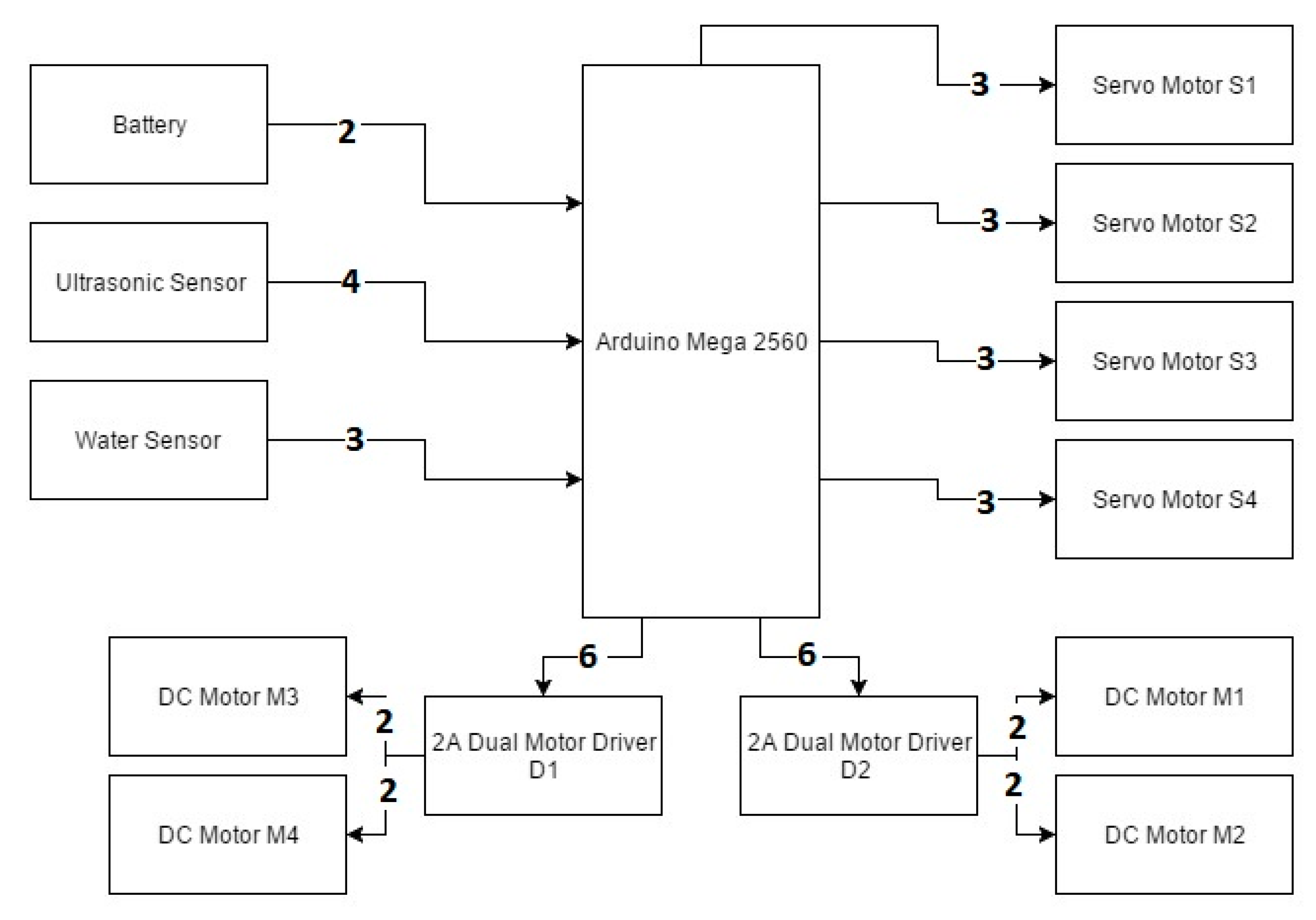
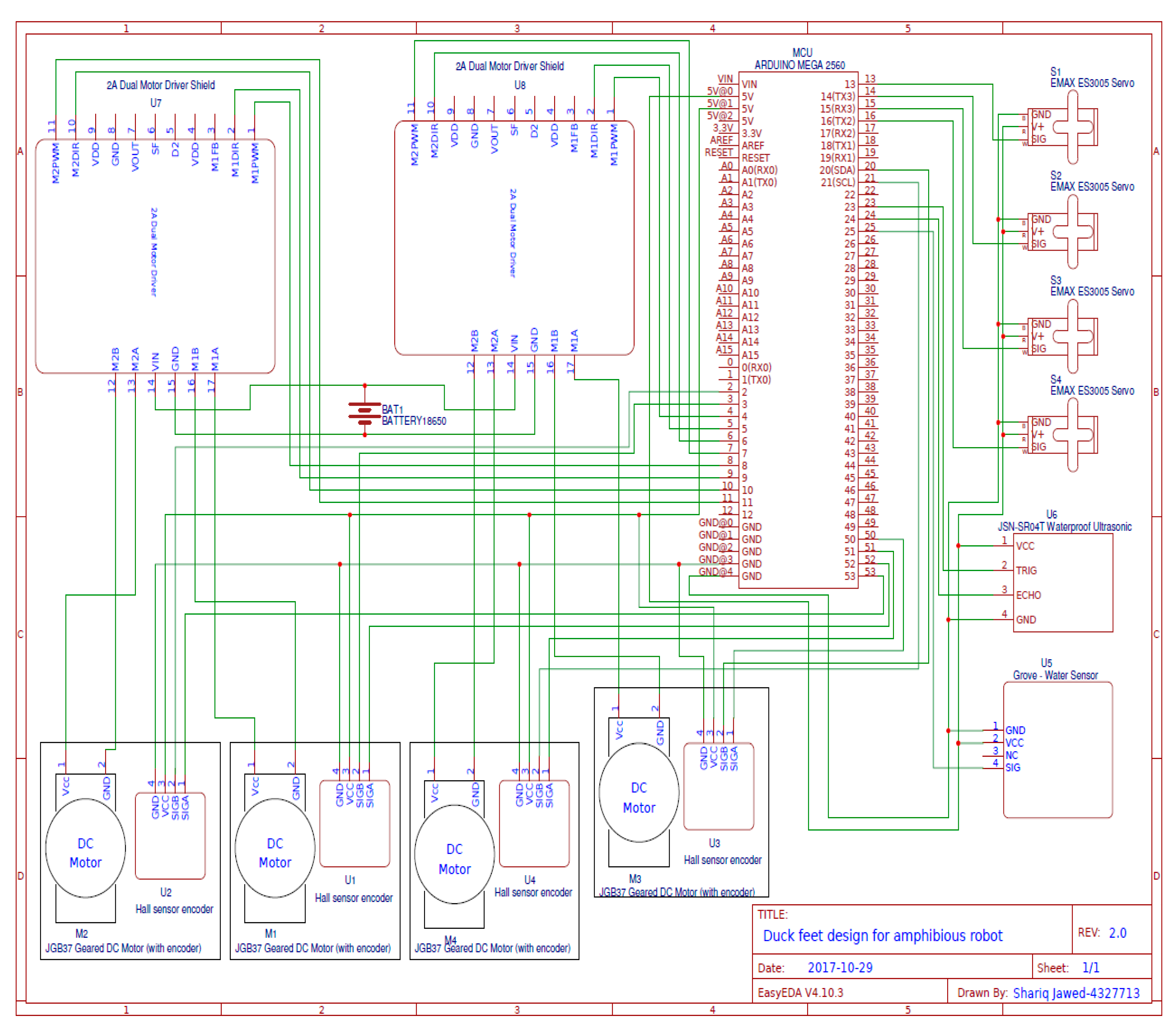
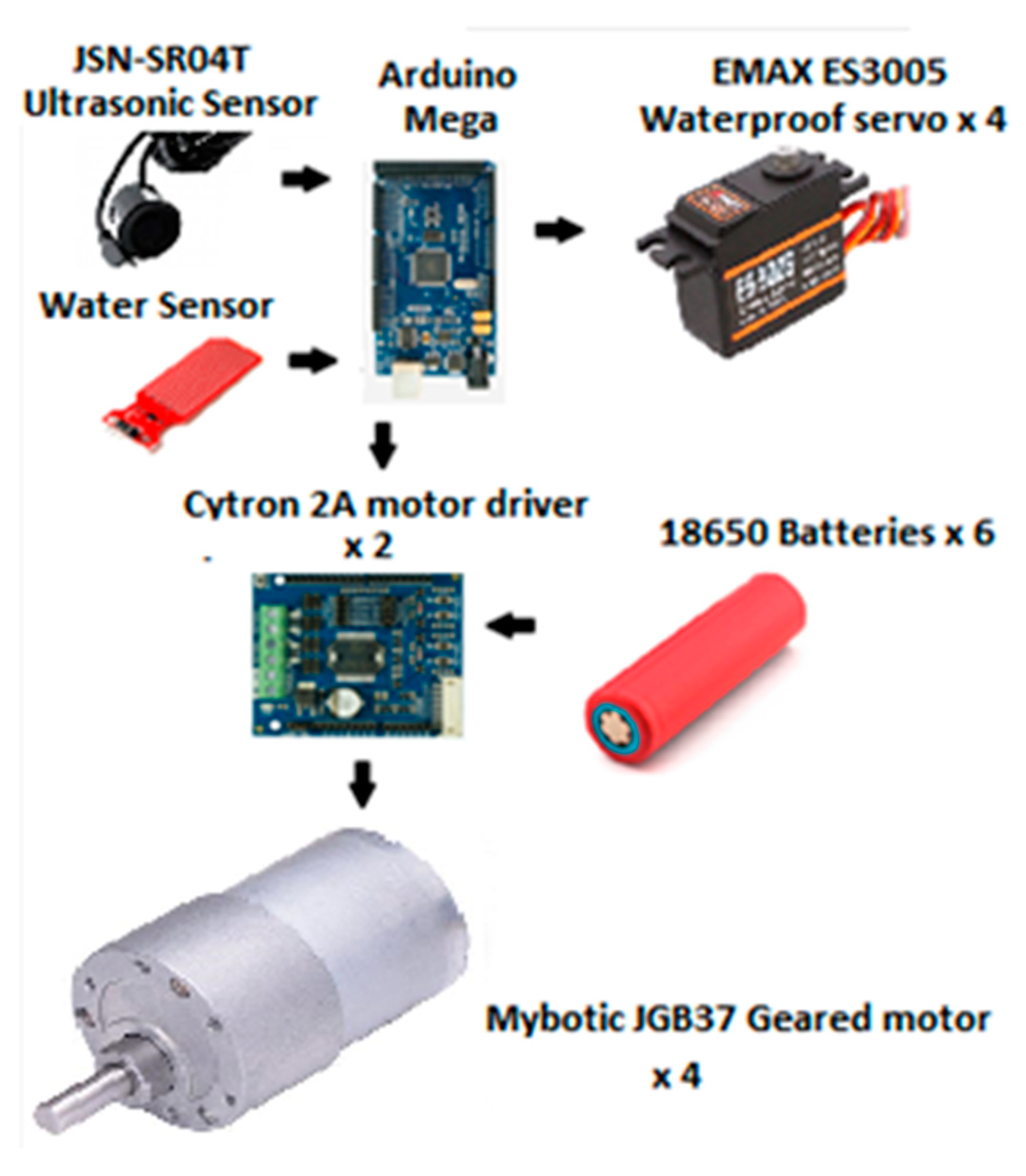
3.2. Electrical Design
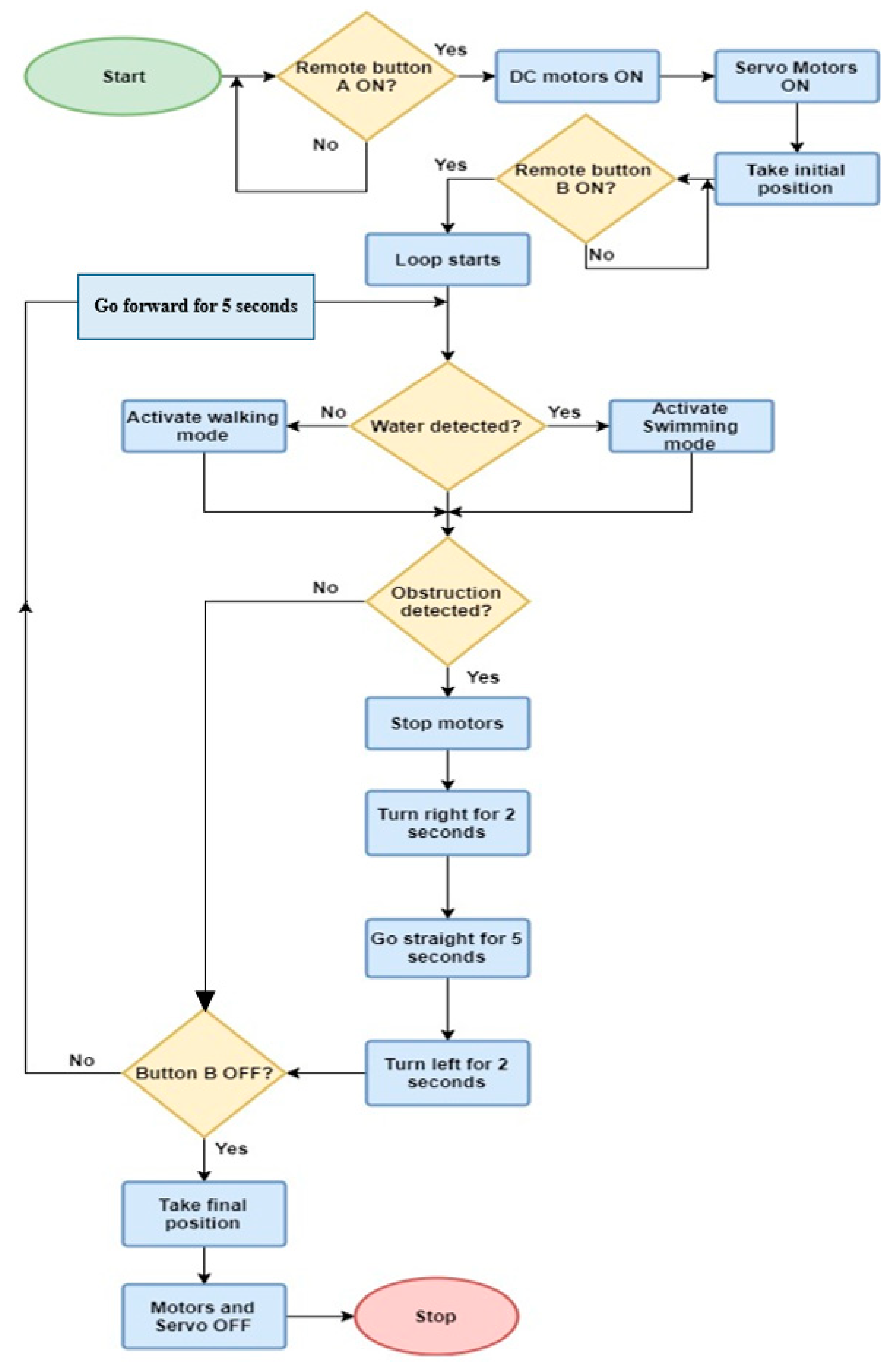
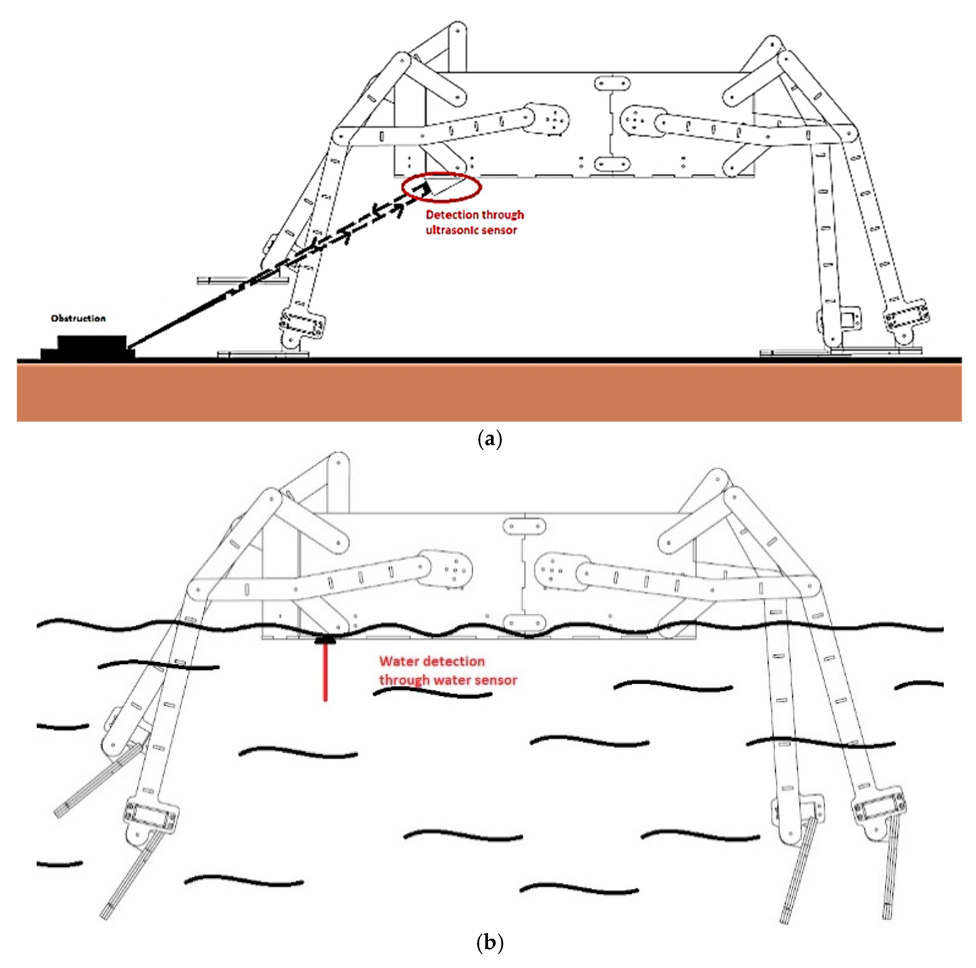
3.3. Program Flow
4. Discussion and Results
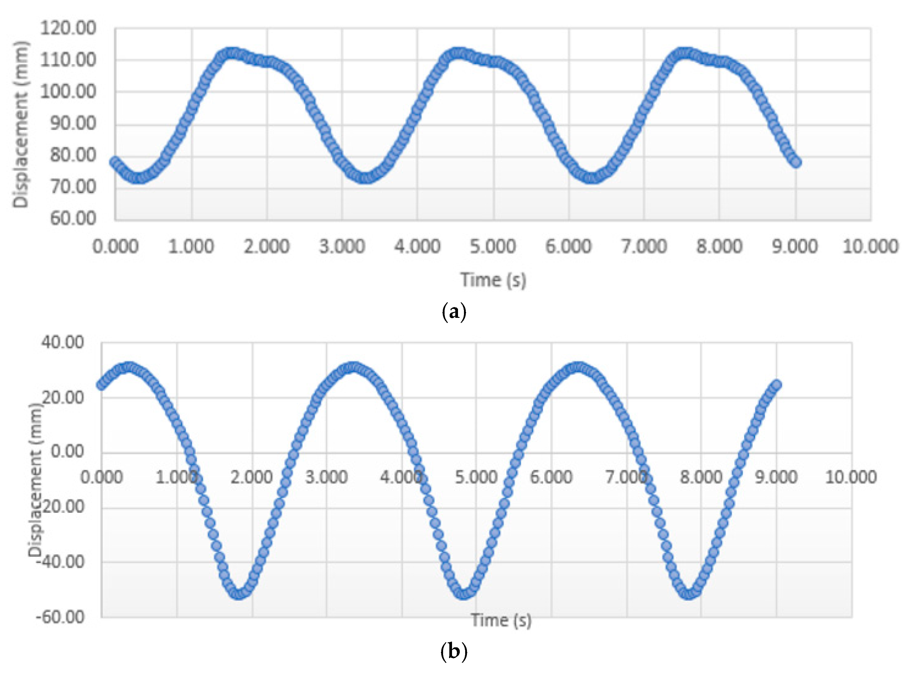
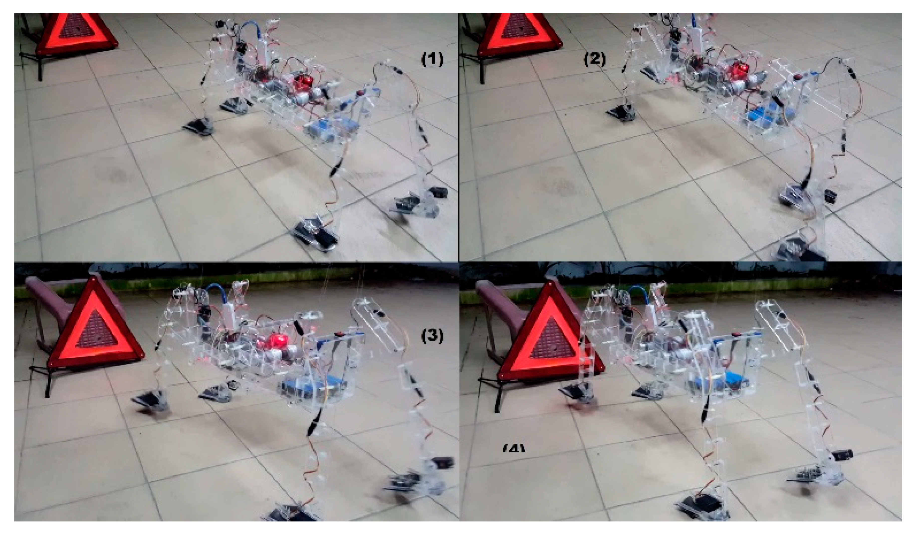
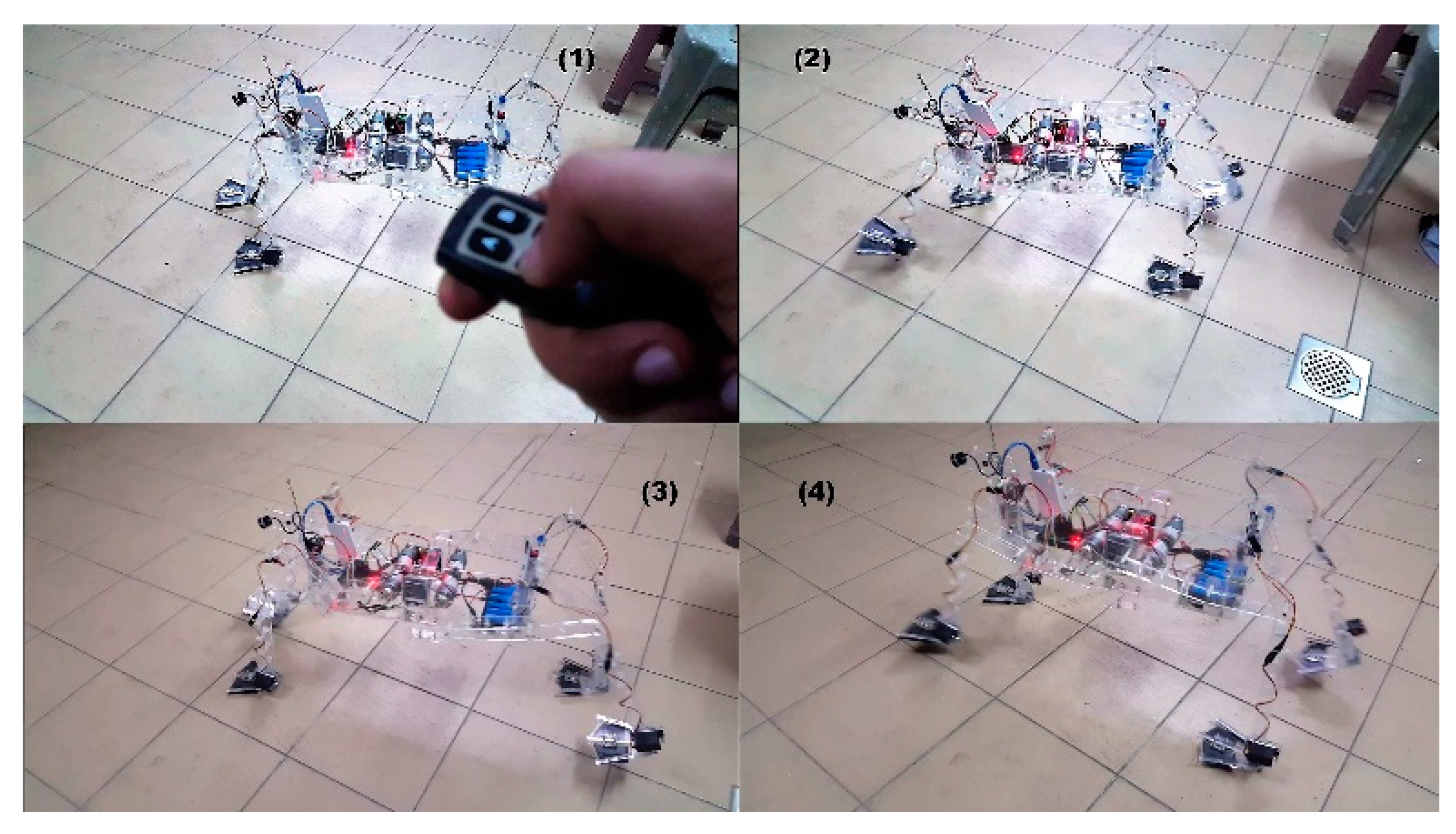
4.1. Walking Test
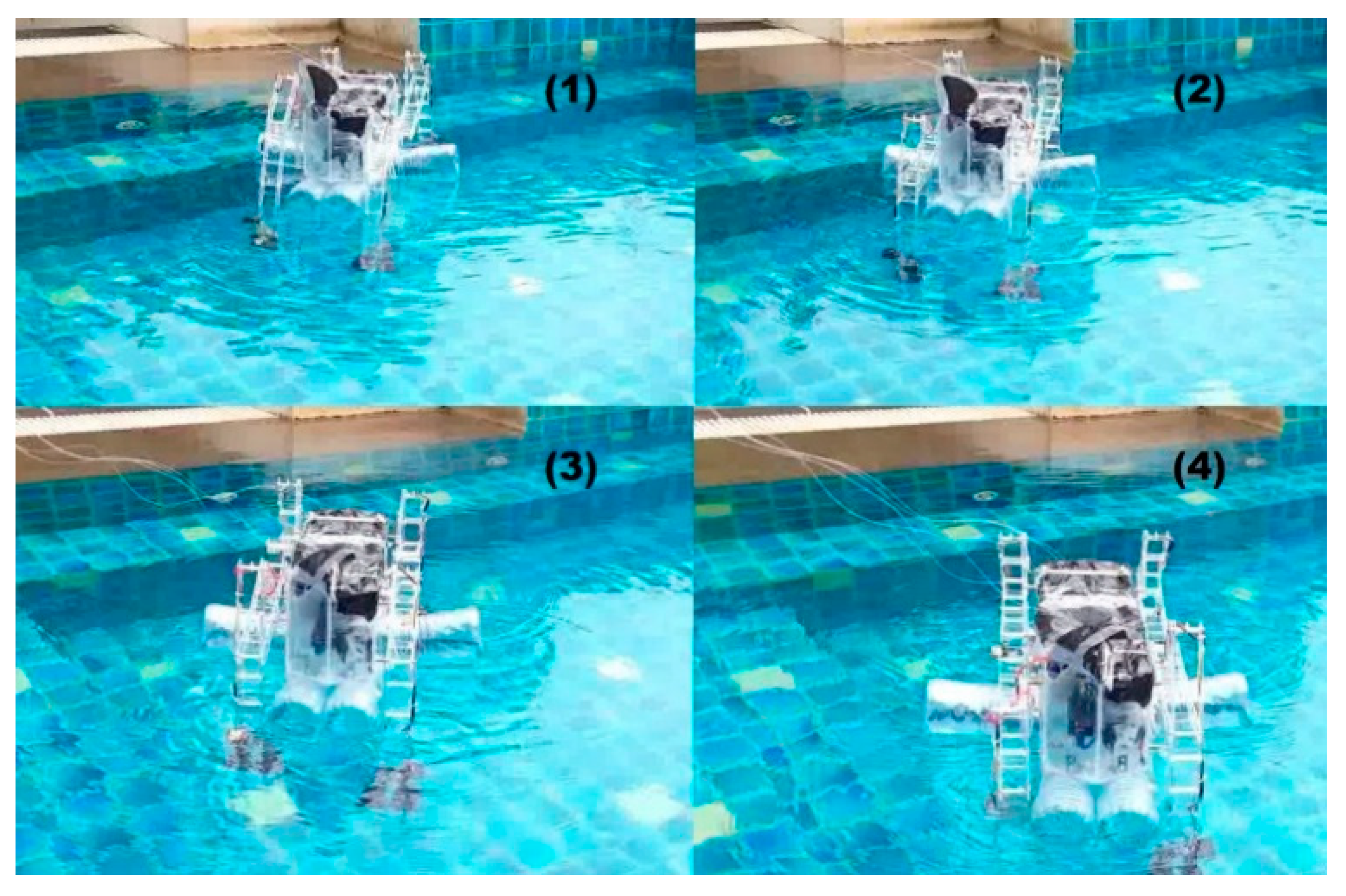
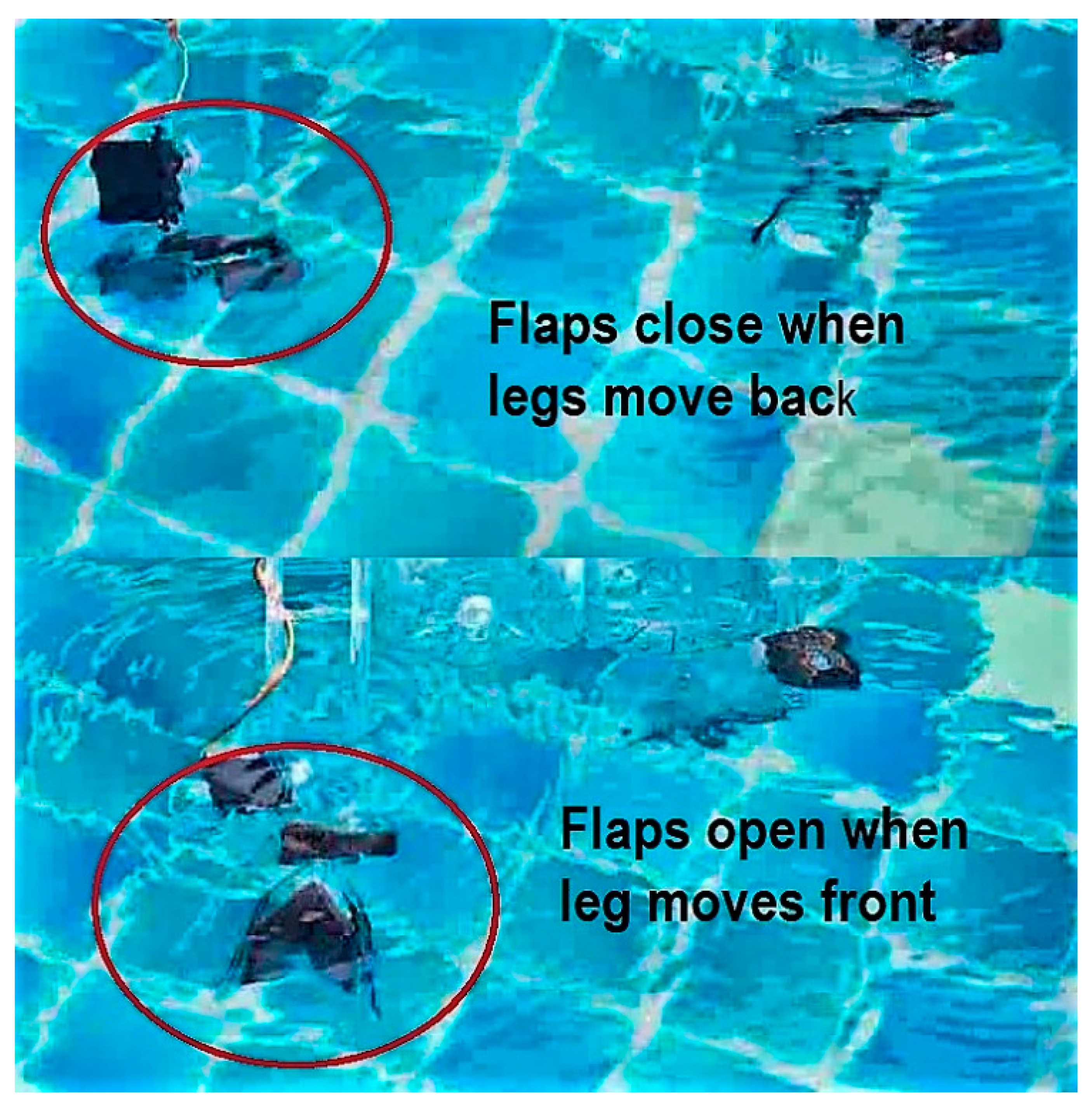
4.2. Swimming Test
5. Conclusions and Future Work
Author Contributions
Funding
Conflicts of Interest
References
- Kashem, S.B.A.; Jawed, S.; Ahmed, J.; Iqbal, A. An experimental study of the amphibious robot inspired by biological duck foot. In Proceedings of the 2018 IEEE 12th International Conference on Compatibility, Power Electronics and Power Engineering (CPE-POWERENG 2018), Doha, Qatar, 10–12 April 2018; pp. 1–6. [Google Scholar]
- Dai, Y.; Zheng, Z.Q.; Chen, J.L.; Chang, Z.Y. Design of a new propulsion mechanism of imitating duck’s webbed-feet. Telkomnika Indones. J. Electr. Eng. 2013, 11, 4735–4741. [Google Scholar] [CrossRef]
- Ijspeert, A.J. Central pattern generators for locomotion control in animals and robots: A review. Neural Netw. 2008, 21, 642–653. [Google Scholar] [CrossRef]
- Li, N.; Ma, S.; Wang, M.; Li, B.; Wang, Y. An optimization design method for the mechanism parameters of an amphibious transformable robot. In Proceedings of the 2012 IEEE/RSJ International Conference on Intelligent Robots and Systems, Vilamoura, Portugal, 7–12 October 2012; pp. 2282–2288. [Google Scholar]
- Yang, Y.; Zhou, G.; Zhang, J.; Cheng, S.; Fu, M. Design, modeling and control of a novel amphibious robot with dual-swing-legs propulsion mechanism. In Proceedings of the 2015 IEEE/RSJ International Conference on Intelligent Robots and Systems (IROS), Hamburg, Germany, 28 September–2 October 2015; pp. 559–566. [Google Scholar]
- Yu, J.; Ding, R.; Yang, Q.; Tan, M.; Wang, W.; Zhang, J. On a bio-inspired amphibious robot capable of multimodal motion. IEEE/ASME Trans. Mechatron. 2011, 17, 847–856. [Google Scholar] [CrossRef]
- Kim, H.J.; Song, S.H.; Ahn, S.H. A turtle-like swimming robot using a smart soft composite (SSC) structure. Smart Mater. Struct. 2012, 22, 014007. [Google Scholar] [CrossRef]
- Chen, X.; Wang, G.; Yan, X.; Xie, J. Experimental and numerical study on subsea swimming gait for a shoal crab robot. In Proceedings of the OCEANS 2016—Shanghai, Shanghai, China, 10–13 April 2016; pp. 1–6. [Google Scholar]
- Rahman, M.M.; Toda, Y.; Miki, H. Computational study on a squid-like underwater robot with two undulating side fins. J. Bionic Eng. 2011, 8, 25–32. [Google Scholar] [CrossRef]
- Crespi, A.; Karakasiliotis, K.; Guignard, A.; Ijspeert, A.J. Salamandra robotica II: An amphibious robot to study salamander-like swimming and walking gaits. IEEE Trans. Robot. 2013, 29, 308–320. [Google Scholar] [CrossRef]
- Silva, M.F.; Machado, J.T. A literature review on the optimization of legged robots. J. Vib. Control 2012, 18, 1753–1767. [Google Scholar] [CrossRef]
- Raibert, M.; Blankespoor, K.; Nelson, G.; Playter, R. Bigdog, the rough-terrain quadruped robot. IFAC Proc. Vol. 2008, 41, 10822–10825. [Google Scholar] [CrossRef]
- Lokhande, N.G.; Emche, V.B. Mechanical spider by using Klann mechanism. Int. J. Mech. Eng. Comput. Appl. 2013, 1, 13–16. [Google Scholar]
- Zhang, Z.G.; Kimura, H. Rush: A simple and autonomous quadruped running robot. Proc. Inst. Mech. Eng. Part I J. Syst. Control Eng. 2009, 223, 323–336. [Google Scholar] [CrossRef]
- Sheba, J.K.; Martínez-García, E.; Elara, M.R.; Tan-Phuc, L. Design and evaluation of reconfigurable Klann mechanism based four legged walking robot. In Proceedings of the 2015 10th International Conference on Information, Communications and Signal Processing (ICICS), Singapore, 2–4 December 2015; pp. 1–5. [Google Scholar]
- Ribak, G.; Swallow, J.G.; Jones, D.R. Drag-based ‘hovering’ in ducks: The hydrodynamics and energetic cost of bottom feeding. PLoS ONE 2010, 5, 12565. [Google Scholar] [CrossRef]
- Li, M.; Guo, S.; Hirata, H.; Ishihara, H. Design and performance evaluation of an amphibious spherical robot. Robot. Auton. Syst. 2015, 64, 21–34. [Google Scholar] [CrossRef]
- Dhull, S.; Canelon, D.; Kottas, A.; Dancs, J.; Carlson, A.; Papanikolopoulos, N. Aquapod: A small amphibious robot with sampling capabilities. In Proceedings of the 2012 IEEE/RSJ International Conference on Intelligent Robots and Systems, Vilamoura, Portugal, 7–12 October 2012; pp. 100–105. [Google Scholar]
- Dudek, G.; Giguere, P.; Prahacs, C.; Saunderson, S.; Sattar, J.; Torres-Mendez, L.A.; Jenkin, M.; German, A.; Hogue, A.; Ripsman, A.; et al. Aqua: An amphibious autonomous robot. Computer 2007, 40, 46–53. [Google Scholar] [CrossRef]
- Liang, X.; Xu, M.; Xu, L.; Liu, P.; Ren, X.; Kong, Z.; Yang, J.; Zhang, S. The AmphiHex: A novel amphibious robot with transformable leg-flipper composite propulsion mechanism. In Proceedings of the 2012 IEEE/RSJ International Conference on Intelligent Robots and Systems, Vilamoura, Portugal, 7–12 October 2012; pp. 3667–3672. [Google Scholar]
- Kashem, S.; Sufyan, H. A novel design of an aquatic walking robot having webbed feet. Int. J. Autom. Comput. 2017, 14, 576–588. [Google Scholar] [CrossRef]
- Kashem, S.B.A.; Sheikh, M.I.B.; Ahmed, J.; Tabassum, M. Gravity and buoyancy powered clean water pipe generator. In Proceedings of the 2018 IEEE 12th International Conference on Compatibility, Power Electronics and Power Engineering (CPE-POWERENG 2018), Doha, Qatar, 10–12 April 2018; pp. 1–5. [Google Scholar]
- Kashem, S.B.A.; Ektesabi, M.; Nagarajah, R. Comparison between different sets of suspension parameters and introduction of new modified skyhook control strategy incorporating varying road condition. Veh. Syst. Dyn. 2012, 50, 1173–1190. [Google Scholar] [CrossRef]
- Kashem, S.; Nagarajah, R.; Ektesabi, M. Vehicle Suspension Systems and Electromagnetic Dampers; Springer: Singapore, 2018. [Google Scholar]
- Kashem, S.B.A.; Roy, S.; Mukharjee, R. A modified skyhook control system (SKDT) to improve suspension control strategy of vehicles. In Proceedings of the 2014 International Conference on Informatics, Electronics & Vision (ICIEV), Dhaka, Bangladesh, 23–24 May 2014; pp. 1–8. [Google Scholar]
- Kashem, S.B.A.; Tabassum, M.; Chai, M. A novel design of an amphibious robot having webbed feet as duck. In Proceedings of the 2017 International Conference on Computer and Drone Applications (IConDA), Kuching, Malaysia, 9–11 November 2017; pp. 17–21. [Google Scholar]


© 2019 by the authors. Licensee MDPI, Basel, Switzerland. This article is an open access article distributed under the terms and conditions of the Creative Commons Attribution (CC BY) license (http://creativecommons.org/licenses/by/4.0/).
Share and Cite
Kashem, S.B.A.; Jawed, S.; Ahmed, J.; Qidwai, U. Design and Implementation of a Quadruped Amphibious Robot Using Duck Feet. Robotics 2019, 8, 77. https://doi.org/10.3390/robotics8030077
Kashem SBA, Jawed S, Ahmed J, Qidwai U. Design and Implementation of a Quadruped Amphibious Robot Using Duck Feet. Robotics. 2019; 8(3):77. https://doi.org/10.3390/robotics8030077
Chicago/Turabian StyleKashem, Saad Bin Abul, Shariq Jawed, Jubaer Ahmed, and Uvais Qidwai. 2019. "Design and Implementation of a Quadruped Amphibious Robot Using Duck Feet" Robotics 8, no. 3: 77. https://doi.org/10.3390/robotics8030077
APA StyleKashem, S. B. A., Jawed, S., Ahmed, J., & Qidwai, U. (2019). Design and Implementation of a Quadruped Amphibious Robot Using Duck Feet. Robotics, 8(3), 77. https://doi.org/10.3390/robotics8030077