Abstract
The overall control system for an open-frame Remotely Operated Vehicle (ROV) is typically built from three subsystems: guidance, navigation and control (GNC). The control allocation plays a vital role in the control subsystem. Typically, open-frame underwater vehicles have p actuators (thrusters) for the motion in the horizontal plane, and the control allocation problem, in this case, is very complex and hard to visualise, because the normalised constrained control subset is a p-dimensional unit cube. The aim of this paper is to give a clear picture and a geometric interpretation of the problem and to introduce a hybrid method, based on the integration of a weighted pseudoinverse and the fixed-point method. The main idea of the hybrid method is visualised, and the deep geometric insight is provided using a “virtual” ROV in low-dimensional control spaces, including visualisation of the attainable command set, solution lines, control energy spheres and the role of pseudoinverse and fixed-point iterations. The same concepts are then extended to higher-dimensional cases, for open-frame ROV with four X-shaped (vectored) horizontal thrusters, which is one of the most common thruster configurations for commercial ROVs. The proposed hybrid method has been developed, integrated into a generic fault-tolerant ROV control system and evaluated in virtual and real-world environments off the west coast of Ireland using observation-class ROV Latis and work-class ROV Étaín.
1. Introduction
In general, a fault is the primary cause of changes in the system structure or parameters that eventually leads to degraded system performance or even the loss of the system function. A Fault-Tolerant Control (FTC) system continuously analyses the behaviour of the plant in order to identify faults and changes the control law to hold the closed-loop system in a region of acceptable performance. Fault tolerance includes two steps [1]: (i) Fault diagnosis (the existence of faults has to be detected, and the faults have to be identified); (ii) Control re-design (the controller has to be adapted to the faulty situation so that the overall system continues to have satisfactory performance). Like faults, disturbances and model uncertainties change the plant behaviour and have similar effects on the system. Disturbances and model uncertainties are nuisances which are known to exist, but whose effects on the system performance are handled by appropriate measures like filtering or robust design. On another side, the FTC system is designed to detect the faults and remove their effects by remedial actions, i.e., it is aimed to change the control law in order to cancel the effects of the faults or to attenuate them to an acceptable level.
Control allocation is an effective approach to implement fault-tolerant control. An overview of control allocation methods is given in [2] (for aerospace applications) and [3] (for marine applications). In survey article [4], authors intended to encourage the cross-disciplinary transfer of ideas between various application fields, with emphasize on optimization-based methods.
Unmanned Underwater Vehicles are subject to faults or failures during underwater missions, and thrusters are one of the most important and most common sources of faults. In all but the most trivial cases, the existence of a fault may lead to mission abortion. Ship time is very expensive, and the implication of small faults could be very costly and time-consuming.
Various fault-tolerant control strategies for unmanned underwater vehicles have been reported in the literature. A fault-tolerant motion control method based on reconstructive approach has been proposed in [5], which is used to ensure the X-rudder Autonomous Underwater Vehicle (AUV) complete the mission in the case of motion actuators failure. An adaptive fault-tolerant controller utilising Radial Basis Function (RBF) neural network sliding mode method was addressed in [6] for a class of Remotely Operated Vehicles (ROVs) with redundant thrusters. Adaptive fault-tolerant control and fault reconstruction problem for AUV subject to ocean current disturbance and modelling uncertainty is investigated in [7]. A virtual closed-loop system is introduced to deal with the influence of the initial tracking error in an ideal environment. Then, the second-order sliding mode observer is constructed to estimate the thruster fault effect. A control allocation method for compensation for the effect of thrusters’ dead zones is proposed in [8]. The Dynamic Surface Control (DSC) method for underwater ROVs has been proposed in [9]. Exhaustive simulations have been carried out to compare the performance of the DSC method with respect to different control techniques (PID, backstepping and sliding mode approaches) in fault-free and faulty conditions, with included non-linear effects, such as saturation, actuator dynamics, sensor noises etc. Design of thruster configuration and thrust allocation control for an underactuated ROV is addressed in [10]. The paper proposes the one-norm algorithm and modified singular value method to find appropriate thruster configuration and thrust allocation. Energy-aware fault-mitigation architecture for underwater vehicles has been proposed in [11]. The proposed architecture is capable of detecting faults and monitoring the performance of the thruster subsystem in modern AUVs by observing the use of the onboard resources. Event-Triggered Active Fault-Tolerant Control System is proposed in [12], based on event-triggered transmission mechanism to reduce the amount of data sent to the observer module. The attractive fault-tolerant control scheme for an omni-directional mobile robot with four mecanum wheels, based on the integration of Nonlinear Model Predictive Control module and basic Fault Detection and Isolation scheme, is proposed in [13]. Thrust Distribution Control System for ROVs, based on adaptive back-stepping controller, is proposed in [14]. An overview of existing fault detection and fault-tolerant schemes is presented in [15] and [16].
This paper introduces a geometric insight into the control allocation problem for over actuated open-frame underwater vehicles. The work presented herein is applicable to a wide class of control allocation problems, where the number of actuators is higher than the number of objectives. The paper is aimed to provide deep insight into the geometry of the control allocation problem, and authors hope that it will highlight the problem from a different perspective, based on geometric reasoning.
The paper expands upon the work previously reported by the authors. Thruster fault diagnosis and accommodation system for open-frame underwater vehicles has been proposed in [17]. The extension of the approach with the inclusion of fixed-point iterations is proposed in this paper, and a hybrid method for control allocation is introduced, based on the integration of a weighted pseudoinverse and the fixed-point method. The main idea of the hybrid method is visualised, and the deep geometric insight is provided using a “virtual” ROV in low-dimensional control spaces. Then, the same concepts are extended to higher-dimensional cases, for open-frame ROV with four X-shaped (vectored) horizontal thrusters. The hybrid method for control allocation has been used as a foundation to build the thruster Fault-Tolerant Control system (FTC). The performance of FTC has been evaluated and validated in a virtual and real-world environment. Selected test cases from simulation and field trials demonstrate the effectiveness of the method and the ability of the FTC to complete the mission in the presence of a single (partial and total) fault in a single thruster.
2. Control Allocation Problem
2.1. Problem Definition
The interconnection between Guidance, Navigation and Control (GNC) subsystems for open-frame ROV is shown in Figure 1.
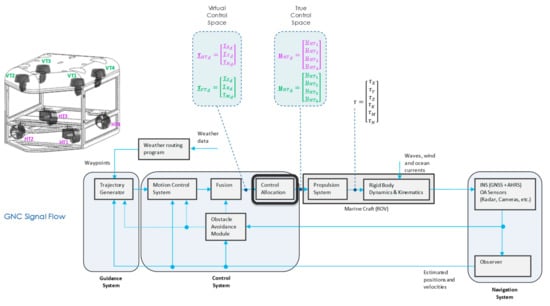
Figure 1.
GNC signal flow for open-frame ROV (inspired by [18]).
- Guidance: subsystem that continuously computes the reference (desired) position, velocity and acceleration of an ROV to be used by the motion control system.
- Navigation: subsystem to determine position/attitude, course, travelled distance and (optionally) velocity and acceleration of an ROV.
- Control: subsystem to determine necessary control forces and moments to be provided by the ROV to satisfy certain control objective (in conjunction with the guidance system).
The control design problem consists of two steps [19]:
- STEP 1 (Regulation Task): Design a control law, which specifies desired virtual control input (normalised vector of forces and moments ) in the virtual control space;
- STEP 2 (Actuator Selection Task): Design control allocator, which finds the “best” feasible true control input (normalised command vector to be applied to individual actuators) in the true control space.
In the GNC Signal Flow shown in Figure 1, the Motion Control System and the Control Allocation components execute STEPS 1 and 2, respectively. After actuation with the control vector , the Propulsion System block will generate a total control effect (vector in Figure 1). After normalisation, this vector should be equal to the desired virtual control input in the case of successful control allocation.
Decomposition of the virtual control input into the horizontal and vertical planes is presented in Table 1.

Table 1.
Decomposition into horizontal and vertical planes.
The main focus of the discussion in the following will be based on the control allocation problem in the horizontal plane. However, a similar approach applies to the vertical plane with minor modifications.
The open-frame ROV with four horizontal thrusters in X-shaped (vectored) configuration and three controllable DOF is shown in Figure 2a, while the top view of thruster configuration in the horizontal plane is shown in Figure 2b. This configuration is the most dominant configuration of horizontal thrusters for commercial ROVs. However, the approach can be easily extended to other configurations.
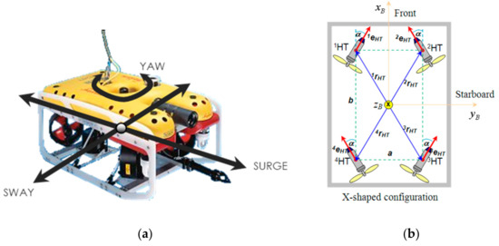
Figure 2.
ROV with 4 HT (X-shaped configuration): (a) Controllable DoF; (b) Thruster configuration.
The axes are chosen to coincide with the principal axes of inertia, and they are defined as:
- —longitudinal axes (directed to front side),
- —transversal axes (directed to starboard),
- —normal axes (directed from top to bottom).
For open-frame ROV, shown in Figure 2, dimensions of virtual and true control spaces are and , respectively. For full geometric insight into underlying control allocation problem, the main difficulty is the inability to easily visualise what is happening in 4D true control space during the execution of control allocation solution steps.
To overcome this issue and to provide a clear picture into the geometry of the control allocation solution steps, an artificial “virtual” ROV is introduced (Figure 3), with very specific star configuration of the horizontal thrusters, such that the dimensions of control spaces are reduced by one, i.e., dimensions of virtual and true control spaces are and , respectively. Introduction of the “virtual” ROV provides a framework to visualise concepts and all steps of the solution using 2D/3D figures, including the attainable command set, the shape of control energy spheres, solution lines, pseudoinverse solution, and cases for triggering the fixed-point iterations. The most important feature of the star configuration is the inability of thrusters to create a moment and rotate “virtual” ROV since all thruster axes intersect in a common point, as indicated in Figure 3. Hence, two controllable DoFs are Surge and Sway, while Yaw DoF is not controllable.
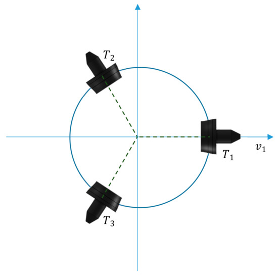
Figure 3.
“Virtual” ROV with 3 HT (star thruster configuration).
To simplify notation, the underline and subscript d will be removed from normalised variables in the following text. When vectors/variables are not normalised, it will be stated explicitly. Based on the normalisation method described in [7], the general constrained problem for the “virtual” ROV, and the open-frame ROV can be formulated using normalised variables as indicated in Table 2.

Table 2.
Control Allocation Problem for “virtual” ROV and open-frame ROV.
In general case, the equation defines the set of hyperplanes in the true control space . The intersection of these hyperplanes is a convex set, denoted by . The set of inequalities represents the hyper box in the same space. This hyper box is called constrained (admissible) control subset and denoted by . The solution set is given by the intersection of and . Three cases are possible:
- is empty (i.e., no solution exists),
- has exactly one element (i.e., there is one unique solution),
- has more than one element (i.e., there are many solutions).
The following discussion is limited to Control Allocation Problem for the “virtual” ROV. Equation (1) represents a system of equations
Each Equation in (5) represents a plane in . Consequently, (5) can be rewritten as
where and are normal vectors, orthogonal on planes and , respectively. Since the determinant , these planes are not parallel, and their intersection is a line :
where is the parameter of the line. The line is a convex set, denoted by in the previous discussion. The constrained control subset , which satisfies actuator position constraints (2), is a unit cube in :
Geometric interpretation of the control allocation problem can be obtained by reformulating the problem as follows:
Three cases are possible:
- If the intersection is a segment, there is an infinite number of solutions (each point that belongs to the segment is a solution),
- If the intersection is a point, there is only one solution,
- If the intersection is an empty set, no solution exists.
The output of the Control Allocation subsystem in Figure 1 must be a single vector for all three cases. In the first case above, a secondary criterion (like minimum control energy) is introduced to select a unique solution. In the third case above, the “best” approximation is used as the output of the algorithm. All three cases are discussed in the following in more details.
2.2. Nomenclature
The following nomenclature is adopted for referring to , shown in Figure 4 [20]:
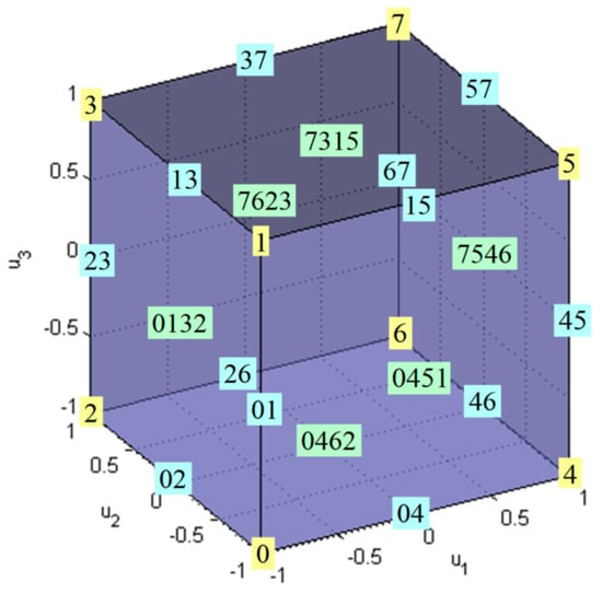
Figure 4.
The constrained control subset for “virtual” ROV.
The boundary of is denoted by . A true control vector belongs to if and only if at least one of its components is at a limit (−1 or +1). Vertices are the points on where each component receives a limit (min or max). In Figure 4, vertices are denoted as , , …, . In the general case, the number of vertices is equal to . Vertices are numerated using the following rule: if the vertex is represented in a binary form, then “” in the position of this representation indicates that the corresponding component is at a minimum , while ″″ indicates it is at a maximum . For example, binary representation for the vertex is . Using the rule it can be decoded as , which refers to the vertex generated by , , . Edges are lines that connect vertices and that lie on . In Figure 4 edges are denoted as , ,…, . They are generated by varying only one of the components, while the remaining are at their limits, associated with the two connected vertices. In the general case, the number of edges is equal to . Two vertices are connected by an edge if and only if their binary representations differ in only one bit. For example, vertices and are connected by an edge , because their binary representations ( for , for ) differ in only one (last) bit. In contrast, vertices and are not connected by an edge, because their binary representations ( for , for ) differ in more than one bit.
Facets are plane surfaces on that contain two adjacent edges, i.e., two edges that have a common vertex. In Figure 4, facets are denoted as , , …, . In the general case, the number of facets is equal to . A facet is defined as the set in the true control space obtained by taking all but two components at their limits and varying the two free components within their limits. For example, for facet binary representations of its vertices are for , for , for and for . It can be seen that the first digit in these representations is fixed, while the other digits are not fixed, indicating that on this facet the first component is fixed at the limit , while the other two components and are free to vary between their limits .
In the virtual control space the allowable virtual control subset (Figure 5) is defined as a set of all allowable virtual control inputs (unit square in :
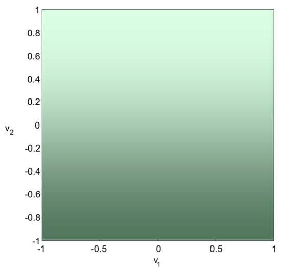
Figure 5.
The allowable virtual control subset for “virtual” ROV.
2.3. Geometric Insight into Problem
Equation (1) defines a linear transformation from the true control space to the virtual control space , which maps (projects) the constrained control subset (unit 3D cube) into attainable command set (Figure 6).
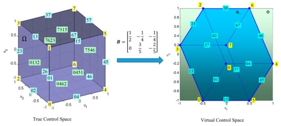
Figure 6.
The control effectiveness matrix maps (projects) the constrained control subset into attainable command set .
In the general case, the optimal true control input is given by the solution to a two-step optimisation problem [9]:
where represents preferred positions of the actuator inputs (preferred true control input) and and are weighting matrices. The problem defined with (11)–(12) can be interpreted as follows: given , the set of feasible control inputs that minimise (weighted by ), find the true control input that minimises (weighted by ). In Equations (11) and (12) , , and are design parameters. The choice of may correspond, for example, to minimum control deflections in aerospace applications. The non-actuated state of the horizontal thrusters is a preferred state for an ROV, i.e., preferred true control input in (11) is . Matrix can be used for actuator prioritisation, i.e., which actuator should be used primarily. Similarly, matrix allows for prioritisation among the virtual control inputs when the problem (11)–(12) has no exact solution. Geometric interpretation of (11)–(12) for “virtual” ROV is given in the following example.
Example 1.
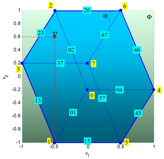
Consider the control allocation problem (1)–(2) and let
is the desired virtual control input (Figure 7). Let the optimisation objective be given by (11)–(12), with , , .

Figure 7.
Position of the desired virtual control input in .
Since , i.e., is attainable, the problem (11)–(12) can be reduced to
subject to
Substituting and in (7) yields the following solution line
The intersection (solution set) of (16) and (8) is a segment , where (for ) and (for ) (see Figure 8). The points and belong to facets and , respectively. The solution of the problem is a point on the segment that minimises . Hence, the solution depends on the choice of the norm.
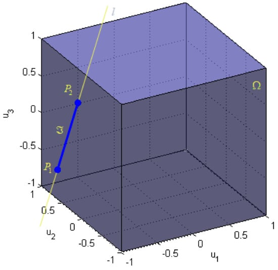
Figure 8.
Solution line and solution set .
2.4. Choice of Norm
It is useful to analyse the relationship between the choice of the norm , the weighting matrix and the solution of the control allocation problem for fault-free and faulty situations.
A set of points that satisfy the condition is called a weighted sphere . A family of spheres can be obtained by varying radius . The optimal solution is a point where a family of these spheres, centred at and weighted by , “touch” the set .
Figure 9 illustrates the situation for norm. The family of spheres is represented by concentric diamond-shaped bodies. If the radius of spheres is increased, for certain value the sphere will touch the segment . The touching point is a solution, which minimises and .
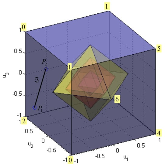
Figure 9.
Family of spheres for norm.
Case is illustrated in Figure 10. Now the shape of the sphere is familiar from the Euclidian metric. The same procedure, as described above, can be applied again: if the radius of spheres is increased, for certain value the sphere will touch the segment . The touching point is a solution, which minimise and .
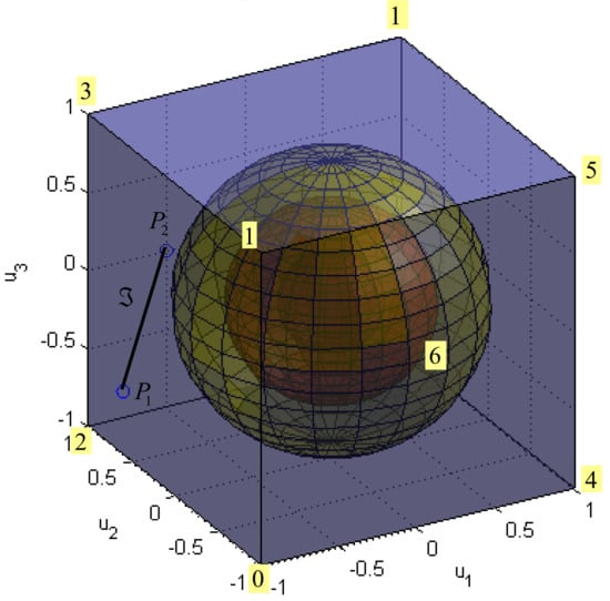
Figure 10.
Family of spheres for norm.
Remarks 1.
- In the case when is the unity matrix, the norm distributes the virtual control demand among the control inputs in a uniform way, while the solution utilises as few control inputs as possible to satisfy the virtual control demand.
- The solution varies continuously with the parameters (elements) of , while the solution does not. Change in a parameter (element) of will produce the change in the slope of . The solution will vary continuously with , while it can be shown that the solution will have discontinuity for some value of and the solution in the breakpoint is not unique.
- If is a non-singular, the problem has a unique solution for . For , this is not always the case, as discussed above. The reason lies in the fact that the sphere is a strictly convex set, while this is not the case for .
In the following, it is assumed that , i.e., that the norm is used as a measure of how good a solution (or approximation) is. This norm represents a measure of control effort and norm of solution (11) can be interpreted as control energy cost function.
2.5. Choice of the Weighting Matrix
The matrix is a design parameter typically used for actuator prioritisation. If all actuators have the same priority, then is equal to the unit matrix. Otherwise, the weight of the actuator with less priority is increased. In this way, it is possible to accommodate actuator faults by changing the weighting matrix . For example, if , then the faulty horizontal thruster HT3 is penalised for and its contribution to the total control effort is less than in the fault-free case (). Consider the same problem as before, but this time , i.e., . Since , the third actuator has a lower priority than the other two. Geometrically, weighted spheres in the true control space are compressed along the third control axis and become “flattened” spheres, i.e., ellipsoids, as indicated in Figure 11.
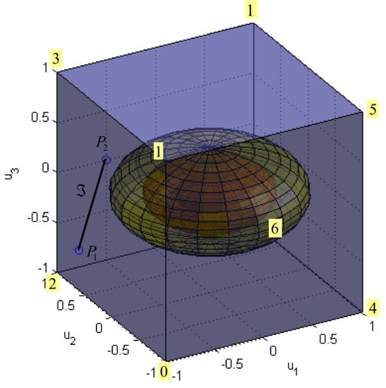
Figure 11.
Family of spheres for norm and case .
In this way, the solution (touching point of the family of ellipsoids with the segment ) exhibits a lower contribution of the third control and higher participation of the other two controls, compared to the previous case, when all actuators had the same priority. The additional introduction of nonzero off-diagonal elements into the symmetric matrix yields to the rotation of these ellipsoids around the centre.
3. Control Allocation Solution: Hybrid Method
3.1. Description
The hybrid method for control allocation is based on the integration of the weighted pseudoinverse and the fixed-point method and implemented as a two-step process. The weighted pseudoinverse solution is found in the first step. Then, the feasibility of the solution is examined analysing individual components of the solution. If violation of actuator constraint(s) is detected, the fixed-point method is activated in the second step, which results in a guaranteed feasible solution. In this way, the hybrid method can allocate the exact solution, optimal in the sense, inside the entire attainable command set. This solution minimises the control energy cost function, which is the most suitable criteria for underwater applications.
3.2. Weighted Pseudoinverse
3.2.1. Introduction
The first step of the hybrid method relies on the fact that an explicit solution to the unconstrained control allocation problem
subject to is given by
where the matrix
is the weighted pseudoinverse of [20]. For “virtual” ROV the matrix is given by
where
For case the weighted pseudoinverse (20) is given by (the change of weights in produces the change in slope of the parallelogram and, consequently, the change in shape of )
The weighted pseudoinverse (18) is mapping from -dimensional virtual control space to -dimensional true control space (Figure 12). The allowable virtual control subset (unit square ) is mapped by the weighted pseudoinverse to a parallelogram . intersection of the parallelogram with the constrained control subset is a convex polygon , where the vertex lies on the edge of .
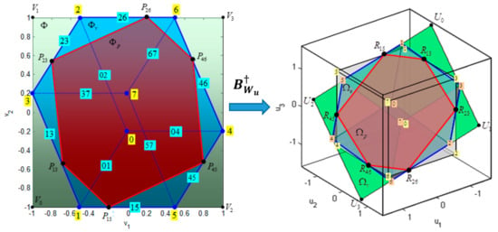
Figure 12.
The Weighted Pseudoinverse as a mapping from Virtual Control Space to True Control Space. Partitions of the Virtual Control Space are: allowable virtual control subset , attainable command set and feasible region for the weighted pseudoinverse . Images of these partitions in the true control space are: , and .
The following discussion will address these issues:
- Find such that ,
- Find .
To find it is sufficient to find points such that
Let and . Then (23) can be rewritten as
The fact that of means that is bounded to the edge defined by vertices and , i.e., two coordinates (controls) of are fixed to their limits, while one is free to vary. Recall that the nomenclature for edges, introduced in Section 2.2, enables easy detection of free and fixed controls for : binary representations of vertices and differ in only one bit and the position of this bit indicates a free control for . For example, the edge is determined by vertices and . The binary representations of () and () differ in the second bit, which means that free control is , while fixed controls are and . Once the fixed and free controls for are obtained, it is easy to find coordinates and of from (24) by removing the equation that corresponds to free control and replacing the right-hand sides of other equations with corresponding limits for fixed controls. For example, for system (24) can be rewritten as
Free control is so the second equation is removed, while the right-hand sides of the first and the third equation are replaced with and , respectively:
which yields the solution and . Other vertices can be found similarly, and results are shown in Table 3 (vertices ) and Table 4 (vertices ). Hence, the subset such that is a convex polygon , whose vertex lies on the edge of (Figure 12).

Table 3.
Vertices of .

Table 4.
Vertices of .
The pseudoinverse image of is a convex polygon . Vertices , , , , and of are mapped to vertices , , , , , of that lie outside , while nodes and of are mapped to nodes and of that lie inside . The virtual control space can be partitioned into three characteristic regions (Figure 12): feasible region for the pseudoinverse (polygon ), (union of triangles , , …, ) and (union of triangles , …, ). The weighted pseudoinverse image of each partition lies inside the parallelogram (Figure 12). Table 5 displays cross-relation between these polygons in the virtual and the true control space.

Table 5.
Cross-relation between the virtual and the true control space.
Subset represents a part of the allowable virtual control subset attainable (feasible) by weighted pseudoinverse. That is, if , then and (see Figure 13). The sphere with the centre at and radius is also shown in Figure 13. This sphere touches the solution line at . In other words, if the virtual control input lies in , then the weighted pseudoinverse solution is the intersection of the solution line and parallelogram , it is feasible and has a minimal norm compared to any other solution. Otherwise, if , then , which means that the virtual control input is not feasible with weighted pseudoinverse, although some other choice of general inverse or application of other methods, like the fixed-point method, could find a feasible solution. This aspect of the relationship between the position of the virtual control input and the feasibility of the solution is important and discussed in the following example.
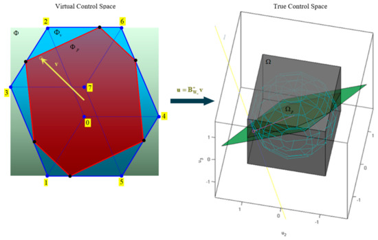
Figure 13.
Geometric interpretation of pseudoinverse: for a given , the weighted pseudoinverse solution is an intersection of the solution line and and has a minimal norm compared to any other solution.
Example 2.
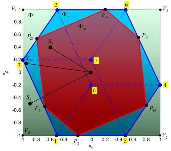
Consider the control allocation problem (1)–(2) and letdenotes an arbitrary point from the allowable virtual control subset. Recall that a total solution setis given by the intersection of the line(7) and. When a pointmoves inside, the corresponding linemoves in the true control space. For a given, the weighted pseudoinverse will select the solution fromwhere the lineintersects the parallelogram. Three characteristic cases are possible, regarding the position ofrelative to the partitions of (Figure 14):

Figure 14.
Three typical cases for the position of virtual control inputs relative to and .
- 1.
- ,
- 2.
- ,
- 3.
- .
Case 2.1: In this case, point lies inside and the weighted pseudoinverse solution is that lies inside (Figure 15). A solution set is a segment . This segment intersects the parallelogram in the point . From all solutions in , the solution , selected by weighted pseudoinverse, is optimal in sense.
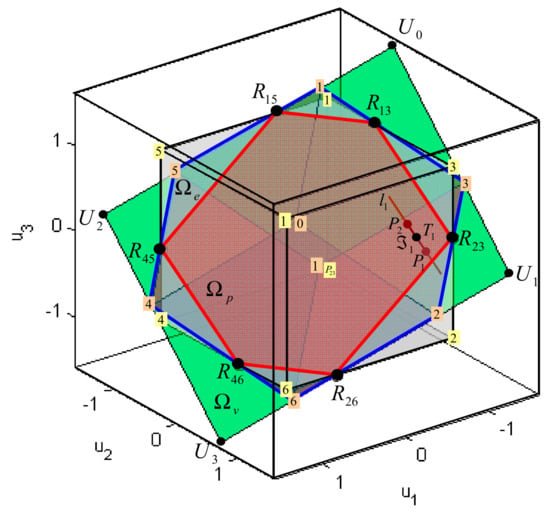
Figure 15.
Case yields to the pseudoinverse solution that is optimal in sense.
For example, if , then the solution set is a segment , , (Figure 15). The weighted pseudoinverse solution () represents the point where the segment intersects the parallelogram . This solution is feasible since it belongs to .
Case 2.2: In this case, point lies outside , but inside . The image lies outside , but inside (Figure 16). Geometrically, a solution set is the segment that does not intersects with , which means that the weighted pseudoinverse solution lies on but outside , i.e., . Hence, the virtual control input is unfeasible (unattainable) by weighted pseudoinverse, but, because is not empty, some other methods (like fixed-point method) can allocate solution from optimal in sense.
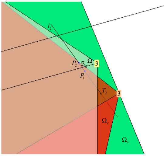
Figure 16.
Case yields to the unfeasible weighted pseudoinverse solution that lies outside .
For example, if , then the solution set is a segment , , (Figure 16). The weighted pseudoinverse solution () represents the point where the line intersects the parallelogram . This solution is unfeasible since it lies on the line outside and does not belong to .
Case 2.3: Finally, in the last case point lies outside , but inside (Figure 17). The image lies outside , but inside (Figure 17). In this case line does not intersect with , i.e., is an empty set, and the exact solution of the problem does not exist. The weighted pseudoinverse solution is unfeasible, since it does not belong to .
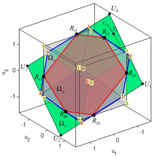
Figure 17.
Case yields to the unfeasible weighted pseudoinverse solution that lies outside .
For example, if , then the solution line (7) is given by
The line does not intersect and the exact solution of the control allocation problem does not exist (Figure 17). However, the intersection of and is the weighted pseudoinverse solution . This solution lies outside and is not feasible.
This example demonstrated that the weighted pseudoinverse could allocate the exact solution (optimal in sense) only if the virtual control input lies in . Otherwise, if , the weighted pseudoinverse finds solutions that lie outside , i.e., that violate control constraints. The approximation of these solutions is the topic of the following section.
3.2.2. Approximation of Unfeasible Solution
If a virtual control input lies outside (for example, and in Figure 14), then the weighted pseudoinverse solution is unfeasible and lies outside , i.e., it violates control constraints ( in Figure 16 and in Figure 17). In this case, it is necessary to approximate unfeasible with feasible such that .
Definition 1.

(Approximation Error): The approximation error is defined as, whereis the virtual control input,is an approximation ofandis an approximation of. To be able to compare different approximations, two scalar errors are introduced: direction error and magnitude error. The direction error represents the angle betweenand, while the magnitude error represents the module of the approximation error vector(Figure 18). In the case when, the approximationpreserves the direction of the original vector.

Figure 18.
Approximation error : (a) Case ; (b) Case .
Two common approximations (Truncation and Scaling) are defined in the following:
Truncation (T-approximation): In this case approximation is obtained from by truncating (clipping) all controls that exceed their control constraints.
Scaling (S-approximation): In this case approximation is obtained from by scaling all components by factor such that .
T-approximations ( and ) and S-approximations ( and ) of unfeasible weighted pseudoinverse solutions (Case 2.2) and (Case 2.3) are shown in Figure 19, respectively.
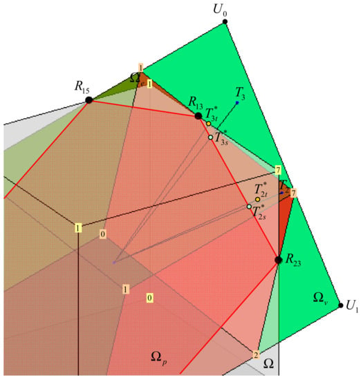
Figure 19.
Approximation of unfeasible pseudoinverse solutions in the true control space.
Remarks 2.
- T-approximation of the unfeasible pseudoinverse solution, introduces direction error , i.e., vectors and have not the same direction. At the same time, the direction error for S-approximation , i.e., vectors and always have the same direction, but the magnitude error is greater than .
- The fixed-point method (Section 3.3) is able to improve the T- or S-approximation of the unfeasible weighted pseudoinverse solution . Approximations or can be used as the initial iteration and the algorithm will find the solution such that is a better approximation of than or . This feature is the main idea of the hybrid approach for control allocation.
3.3. Fixed-Point Method
Introduction
The fixed-point method [21] finds the control vector that minimises
subject to (2), where . The algorithm proceeds by iterating on the equation
where
and is the saturation function that clips the components of the vector to their limits. The condition for stopping the iteration process is
The fixed-point algorithm is very simple, and most computations need to be performed only once before iterations start. The only condition for the initial point is . However, the number of iterations depends on the desired accuracy and the choice of the initial point (solution). To improve efficiency, authors [22] suggest selecting the initial point as the true control input calculated at the previous time sample, i.e., . Design parameters of the fixed-point method are , , and .
Example 3.
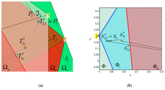

In this example, the fixed-point method is used to find a feasible solution for Case 2.2 from Example 2, optimal in sense. Design parameters are,,and. Results are shown in Figure 20 and Table 6. Since the (unfeasible) pseudoinverse solution has been already found (Figure 16), it is natural to choose the feasible approximation of this solution as the initial point for the iteration. Two choices are available: the T-approximation and S-approximation, obtained by scalingby factor. Fixed-point iterations in the True Control Space are shown in Figure 20a. Individual iterations are shown as black dots if they start from the T-approximation, and as red dots, if they start from the S-approximation. Details about iterations are given in Table 6. If , the fixed-point algorithm converges toward the exact solution, which lies on the solution setand has a lowernorm than any other point in. The corresponding sequence in the virtual control space converges toward the desired (Figure 20b).

Figure 20.
Fixed-points iterations for : (a) True Control Space: Black dots (Red dots) represent iterations starting at (); (b) Virtual Control Space: Black dots (Red dots) represent virtual control inputs related to iterations starting at ().

Table 6.
Iterations of the fixed-point method for .
3.4. Algorithm (Hybrid Method)
Step 1: For a given (), find the weighted pseudoinverse solution.
Step 2: If the solution is feasible, go to Step 4.
Step 3: Use the fixed-point method (Section 3.3) to find a feasible solution.
Step 4: Perform additional modifications (correction for non-symmetrical thrust-speed curves, scaling, type casting, etc.).
Step 5: Deliver the output to the Thruster Interface module.
It should be emphasized that the number of fixed-point iterations, performed to find the feasible solution for cases when the weighted pseudoinverse solution is unfeasible, depends on the desired accuracy and the choice of the design parameters. The desired accuracy is closely related to requirements imposed by the Thruster Interface module. For example, some thruster control protocols require desired velocities to be presented as integer numbers between −100 and +100. This means that the true control space for motion in the horizontal plane is discretised by the uniform grid of discrete control vectors and each solution must be rounded to the closest point in the grid. Design parameters must be chosen to take into account these issues.
3.5. Extension of Concepts from “virtual” ROV to Open-Frame ROV
In previous sections, the main idea of the hybrid method is visualised, and the deep geometric insight is provided using a “virtual” ROV in low-dimensional control spaces, including visualisation of the attainable command set, solution lines, control energy spheres and the role of pseudoinverse and fixed-point iterations. In this section, the same concepts are extended to higher-dimensional cases, for open-frame ROV with four X-shaped (vectored) horizontal thrusters.
Condition (4) for open-frame ROV determines the constrained control subset , that is, the unit 4D cube (the tesseract) in true control space:
The tesseract (35) has 8 cells, faces, edges and vertices. Equation (3) defines a linear transformation from the true control space to the virtual control space , which maps (projects) the tesseract into attainable command set (see Figure 21), a subset of the allowable virtual control subset (the unit 3D cube), defined as
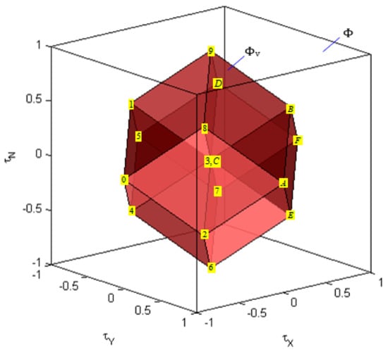
Figure 21.
The allowable virtual control subset and the attainable command set for open-frame ROV.
Coordinates of vertices of and are shown in Table 7. Recall from Section 2.2 that the component values (controls) of in a vertex can be decoded from its binary representation. For example, decoding the binary representation of the vertex yields , , and .

Table 7.
Coordinates of vertices of and .
Considering Equation (3) (system of three linear equations with four unknown variables) from a row perspective, the solution set is the hyper line (the intersection of three hyperplanes in 4D space). The overall solution of the control allocation problem (3)–(4) is a solution set , the intersection of hyper line and . The existence and uniqueness of the solution depends on the position of the virtual control input relative to the attainable command set :
- If lies inside , then has an infinite number of points, and the control allocation problem has an infinite number of solutions.
- If lies on the boundary of , then is a single point, the unique solution for the control allocation problem.
- If lies outside , then is an empty set, i.e., no exact solution exists, only approximation.
For the X-shaped configuration of horizontal thrusters the matrix is given by
Feasibility of the weighted pseudoinverse solution
depends on the position of virtual control input inside the allowable virtual control subset . For a fault-free case, when is the identity (unit) matrix, the shape of the feasible region for the pseudoinverse , defined as a set of virtual control inputs that satisfy (38) subject to , is shown in Figure 22. The boundary of a convex polyhedron represents a set of all virtual control inputs for which at least one component of the pseudoinverse solution (38) receives extreme value. This boundary is determined by the intersection of the four pairs of parallel planes (), , where the plane () represents a set of all virtual control inputs for which kth component of solution (38) satisfies .
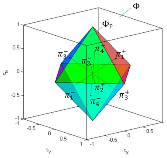
Figure 22.
The feasible region for the weighted pseudoinverse inside the allowable virtual control subset for X-shaped configuration of horizontal thrusters (fault-free case).
The weighted pseudoinverse can find the exact feasible solution of the control allocation problem, optimal in the sense, only if . Geometrically, Equation (38) defines a linear transformation from the virtual control space to the hyperplane in the true control space . The intersection of this hyperplane with the hyper line (solution of ) is the point where the family of weighted hyperspheres “touch” the hyper line. Since , this intersection determines a feasible solution , optimal in sense. The main issue with the weighted pseudoinverse is that the feasible region for the weighted pseudoinverse is a subset of attainable command set (), and the weighted pseudoinverse cannot find an optimal feasible solution on the entire .
Extending ideas from Section 3.2, the allowable virtual control subset can be partitioned into characteristic regions, as indicated in Figure 23. The two characteristic regions inside are and . The weighted pseudoinverse is able to find the exact feasible solution of the control allocation problem, optimal in sense, only if . Otherwise, for , the solution obtained by weighted pseudoinverse is unfeasible. However, the fixed point method can find the solution, optimal in sense, for case . Finally, for case , the solution does not exist, and approximation must be used (for example, T-approximation (truncation) or S-approximation (scaling), as described in Section 3.2.2).
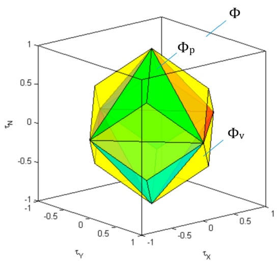
Figure 23.
Partitions of the allowable virtual control subset for X-shaped configuration of horizontal thrusters (fault-free case).
It is useful to visualise the change in shapes of the attainable command set and the feasible region for the weighted pseudoinverse depending on faulty thruster states. In the fault-free state, all thrusters are equally prioritised, and the actuator position constraint in (4) is for each component. In faulty case, faulty thruster HTi is penalised such that . The numerical value of the constraint bound depends on the type of fault.
Change in the constraint bound yields to increase of corresponding weight in the weighting matrix
where
In the faulty case, restriction of constraints bounds reduces the size of the constrained control subset , i.e., is “clipped” to new actuator position constraint for an ith component of . The image of the “clipped” under mapping (3) is reduced attainable command set . Hence, the feasible region for the pseudoinverse and the attainable command set decrease in the case of a fault in the single thruster. In particular, Figure 24a displays only and Figure 24b shows for the case of a partial fault in HT2 (. Analysing (37) and (38), the geometrical interpretation of change in the shape of can be obtained by observing that the change of weight yields the change of slopes of the planes and , , while the planes and with actuator position constraints −0.5 and +0.5 respectively moved closer to the origin, staying parallel, without changing their slopes. The image of the “clipped” constrained control subset is the reduced attainable command set , as shown in Figure 24b. It can be seen that the relation is still valid, i.e., the weighted pseudoinverse is not able to find a feasible solution for case . Similar to the fault-free case, the fixed-point method is triggered in this case, able to find a feasible solution optimal in sense. In this way, the hybrid method allocates the entire attainable command set optimally, despite the limited (restricted) usage of a faulty thruster.
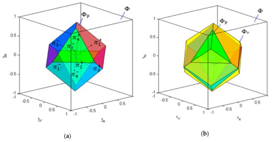
Figure 24.
Partitions of the allowable virtual control subset for X-shaped configuration of horizontal thrusters (partial fault in HT2, ): (a) ; (b) .
Partitions of the allowable virtual control subset for the extreme case (shutdown of HT2) is shown in Figure 25. In particular, Figure 25 displays . for the case of a total fault in HT2 (. This means that the thruster HT2 is disabled and the redundancy is eliminated by removing the variable and the second column of matrix from (3). The modified thruster control matrix is a non-singular square matrix, and the problem can be solved in a standard way. The ratio of volumes of attainable command sets in Figure 24b and Figure 25 relative to the full size (Figure 23), can be used as a measure of loss in manoeuvring capabilities.
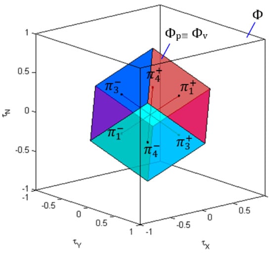
Figure 25.
Partitions of the allowable virtual control subset for X-shaped configuration of horizontal thrusters (total fault in HT2, ): .
The constrained control subset becomes the 3D unit cube, a subset in 4D virtual control space, defined as
is mapped by modified to , which coincides with , as indicated in Figure 25.
4. Testing and Validation
The hybrid method for control allocation, described in this paper, has been used as a foundation to build the thruster Fault-Tolerant Control system (FTC). The performance of FTC has been evaluated and validated in a virtual and real-world environment.
4.1. Evaluation of the FTC in Virtual Environment
In the virtual (simulated) environment thruster faults are simulated by varying properties of the dynamic thruster model (load, friction, etc.) inside the propulsion subsystem of the ROV dynamics simulator. More information about simulation models can be found in (Omerdic, 2009). To enhance the graphical presentation of simulation results, a virtual underwater world has been developed with open-frame ROV model moving in an underwater environment. The relative position of different objects in the underwater world is shown in Figure 26. Three particular objects (the rock with a hole in the middle, long pipe and ″Stonehenge″-like group of rocks) were used throughout the number of test cases to evaluate the manoeuvring capabilities and performance of the ROV when equipped with the FTC. Selected test cases will demonstrate the ability of the FTC to complete the mission in the presence of a single (partial and total) fault in HT2. Diagrams for fault-free and faulty cases are shown next to each other, to provide an easier comparison. Command inputs in test cases were generated using pre-defined signals read from a file.
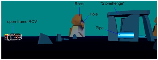
Figure 26.
Virtual underwater world.
Two criteria are introduced to measure control effort over time:
and
The weighted criterion , minimised by the hybrid method, can be interpreted as a weighted control energy cost function. In contrast, the normal criterion represents the actual control energy cost function, that is, a real measure of control effort. In fault-free case , whereas in faulty situations, . Criteria and are denoted in diagrams as and , respectively.
4.1.1. Partial Fault in HT2
This test case compares the performance of the FTC for two cases. In the first case, a simulation was performed assuming fault-free states in all thrusters. The second case considered fault-free states in thrusters HT1, HT3 and HT4, and a faulty state in thruster HT2 (partial fault, ). The same command input vector was used to drive the ROV model in both cases. The mission objective was to move the vehicle from the start point through the pipe along the straight line. Figure 27a displays time diagrams of , , , , , and , the plan view of the trajectory and partitions & of the allowable virtual control subset for the first case. Diagrams for the second case are shown in Figure 27b. It can be seen that, in the fault-free case, the vehicle performs the perfect straight-line motion, vector lies inside for all time and , , . The situation is different for the second case, where the limited usage of HT2 reduction in the size of the and (see Figure 24), and the trajectory becomes partially unfeasible, i.e., lies partially outside . The FTC uses the S-approximation to approximate unfeasible solutions in these cases, which leads to an approximation with the same direction as unattainable command input , but lower magnitude. The unfeasible part of trajectory is characterised by relationship and indicated as shadowed regions in time responses shown in Figure 27b. Pairs of thrusters HT1 & HT2 and HT3 & HT4 are equally actuated for straight-line motion ( and , respectively). The velocity profile follows the profile of , which is now different than , and the vehicle moves slower in shadowed region than in the fault-free case. However, heading is constant in both cases, but trajectories are slightly different. The first difference stems from the fact that the higher forward velocity in the fault-free case means that the vehicle covers a longer distance than in the faulty situation, i.e., . The second difference comes from the shapes of the trajectories . In the first case, it is a perfectly straight line, whereas, in the second case, although symmetrical pairs of thrusters have opposite spin direction coefficients, the vehicle is shifted from the straight line, such that the drift at the endpoint is approximately . The drift is caused by unequal actuation of symmetrical thrusters in the second case, which leads to non-zero angular moments from these pairs, resulting in non-perfect straight-line motion of the vehicle.
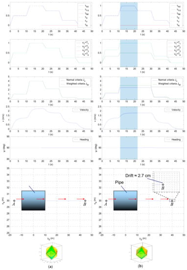
Figure 27.
Partial fault in a single thruster: (a) ; (b) HT2 is faulty ().
This test case demonstrates that, in the presence of a single partial fault in HT2, the faulty vehicle is able to perform straight-line motion with satisfactory performance. An unavoidable effect is a drop in forward velocity for cases when the command input vector lies outside reduced .
4.1.2. Total Fault in HT2
This is an extreme case, where HT2 is switched off, and the mission must be accomplished with three remaining horizontal thrusters. Recall from Figure 25 that and have the same shape (small parallelepiped inside the virtual control space), as indicated in Figure 28b. The volume of and is smaller than in Section 4.1.1, which yields the wider shadowed region, i.e., the larger unfeasible part of the trajectory . Besides, a drop in velocity , is larger for this test case. The faulty vehicle covers the shorter distance () and the drift at the endpoint is approximately . Nevertheless, again the heading is constant for all time.
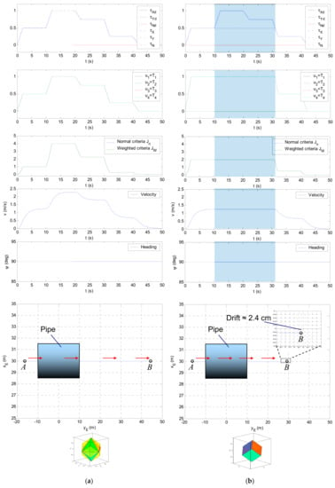
Figure 28.
Total fault in a single thruster: (a) ; (b) HT2 is faulty ().
This test case reveals an important feature of the FTC; that is, despite the presence of a total fault in HT2, which is switched off, the vehicle, equipped with the FTC, is able to continue the straight-line motion and complete the mission with acceptable performance. As in previous cases, the unavoidable consequence is a drop in velocity for cases when the command input vector lies outside reduced .
Materials and Methods should be described with sufficient details to allow others to replicate and build on published results. Please note that publication of your manuscript implicates that you must make all materials, data, computer code, and protocols associated with the publication available to readers. Please disclose at the submission stage any restrictions on the availability of materials or information. New methods and protocols should be described in detail while well-established methods can be briefly described and appropriately cited.
4.2. Evaluation of the FTC in Real-World Environment
The FTC has been used as a foundation for the development of OceanRINGS, a set of smart technologies for subsea operations. The OceanRINGS [23] is a generic fault-tolerant ROV control system, built to make complex subsea tasks simple, and which combines state-of-the-art navigation equipment with the best control algorithms and emerging VR technologies to provide smart, intuitive and easy to use user interface, enabling average pilots to achieve exceptional results. The performance of FTC has been evaluated and validated during several research cruises in period 2009–2019 off the West coast of Ireland using observation-class ROV Latis and work-class ROV Étaín. Smart, multiple modes of operation observation-class ROV Latis [23] (Figure 29a) has been designed at UL in period 2006–2009 and used as a prototype platform to design and develop OceanRINGS modules. The work-class ROV Étaín (modified ROV Comanche by SubAtlantic, Figure 29b) has been extended with OceanRINGS control suite. Dual-mode of operation provides an opportunity to evaluate the performance of both control systems under the same conditions. Selected results from these trials, related to testing of fault-tolerant control system features, are described in the following.
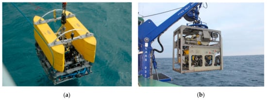
Figure 29.
Underwater robots: (a) observation-class ROV Latis; (b) work-class ROV Étaín.
4.2.1. Path Following: Simulated Faults
The path following test with simulated faults has been performed during the research cruise in Bantry Bay (Figure 30) when ROV Latis has been deployed from support vessel Celtic Voyager in free-swimming mode. Since the vessel Celtic Voyager was not equipped with Dynamic Positioning (DP) system, it used an anchor to hold the position during the test.
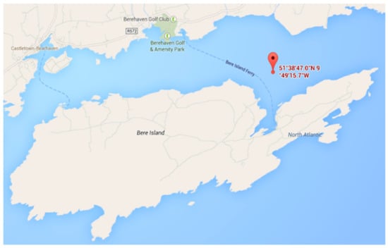
Figure 30.
Location of the research cruise.
The path was defined as a set of waypoints 0, 1, 2, 3, 4 & 5, connected with straight-line segments 01, 12, 23, 34 & 45, as indicated in Figure 31. The main objective was an evaluation of the FTC performance in path following, with simulated faults in single thrusters along the path. Thruster states along path segments are given in Table 8. The main sensor system for navigation, integrated on ROV Latis, was iXBlue PHINS, with several aiding sensors: GAPS USBL, RDI DVL, GPS and Digiquartz pressure depth sensor.
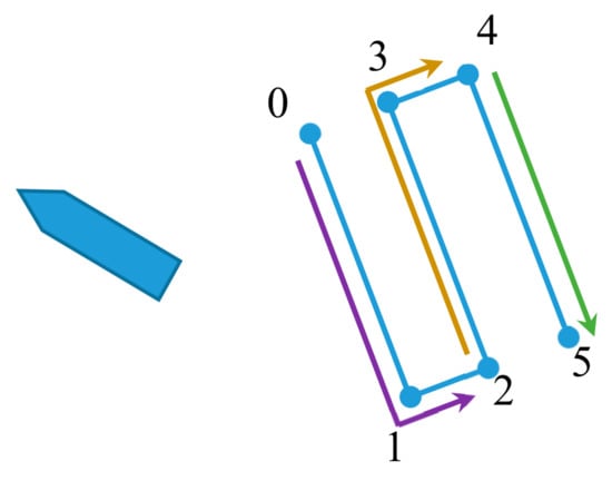
Figure 31.
Path segments.

Table 8.
Thruster states, along with path segments.
Figure 32 shows path-following performance along segment 01, with all thrusters ON. Desired speed was set to . 3D real-time view is shown in the upper right corner, while schematic showing thruster states is shown in the lower right corner. Above ROV 3D model, desired and actual velocity vectors are displayed as green and red cylinders, respectively. Raw ROV position estimation data obtained from the USBL system are shown as a red trace, while the position estimation from PHINS is shown as a yellow trace. The PHINS output has been used for path-following algorithm. “Jumps” in USBL raw data are due to multi-path issues while operating in shallow water ( depth). The anchored support vessel Celtic Voyager was moving in lateral direction oscillating around the fixed position due to high winds. This motion introduced significant pull out forces on ROV via umbilical and the FTC had to compensate this disturbance while performing path following.
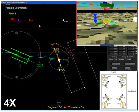
Figure 32.
Path Following: segment 01, all thrusters ON (healthy).
After the way-point 2 has been reached, the total fault in HT4 has been simulated by setting the saturation bound . Figure 33 shows path-following performance along segment 23, with thruster HT4 disabled. No significant deviation from the desired path was noticeable during the transition stage, and ROV continued to follow the path without the change in speed, as indicated in 3D view in the upper right corner (the actual velocity vector (red) has the same module and direction as the desired velocity vector (green)). This performance has been predicted in Section 4.1.2, since the command input vector required to follow desired speed lies inside reduced (Figure 25) all the time on the path segments 23 and 34.
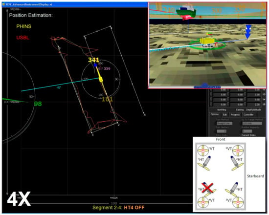
Figure 33.
Path following: segment 23, HT4 OFF (simulated total fault).
After the way-point 4 has been reached, thruster HT4 has been re-enabled (), but the total fault in HT2 has been simulated by setting the saturation bound . Figure 34 shows path-following performance along segment 45, with thruster HT2 disabled. Similar to the previous case, no significant deviation from the desired path was noticeable during the transition stage, and ROV continued to follow the path without the change in speed, as indicated in 3D view in the upper right corner.
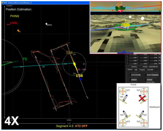
Figure 34.
Path following: segment 45, HT2 OFF (simulated total fault).
4.2.2. Complex Tasks with Faulty Thruster
The performance of FTC has been evaluated and validated during research cruise CE-19001 in January 2019, when the work-class ROV Étaín (Figure 29b), deployed from support vessel Celtic Explorer via Tether Management System (TMS), successfully performed several complex subsea tasks with a simulated fault in the horizontal front-left thruster HT1 ( (Figure 35c).
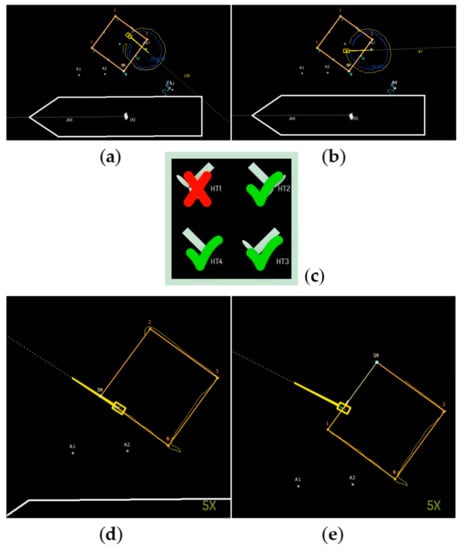
Figure 35.
Testing performance with a fault in single thruster HT1 (c); Circular arc: (a) CCW motion, (b) CW motion; Path following: (d) before WP1, (e) after WP1.
Circular Arc
The main task was to move the ROV with a constant velocity of along the circular arc, with heading pointing toward the centre (Figure 35a,b). The screenshots of CCW and CW trajectories are shown in Figure 34a,b respectively. Desired surge speed was set to , while desired sway speed was set to (CCW motion) and (CW motion). The heading controller used the “Fixed Point” mode, with the ROV heading directed toward the fixed point . In both cases, ROV trajectories were almost perfect circles, demonstrating a high quality of the thruster FTC in performing complex subsea manoeuvring. The same task has been trialled in the manual mode (with a joystick as an input device) by professional ROV pilot with disabled FTC, but the performance was not satisfactory.
Path Following
For this test, ROV had to follow the path (square) defined with four points 0, 1, 2 & 3 with constant speed and constant heading . The screenshots of the main pilot screen during the subsea path following with a fault in a single thruster are shown in Figure 35d,e. In particular, the ROV position approaching the point 1 is shown in Figure 35d. After reaching waypoint 1, the vehicle continued to move toward 2 along the straight-line segment (Figure 35e). The same task has been given to a professional ROV pilot to execute under the same fault conditions, with disabled FTC (Figure 36). The ROV pilot had to maintain the heading and speed by applying manual compensation for unbalanced moment components, due to lack of contribution from the faulty thruster. Non-perfect compensation led to the poor tracking performance and oscillatory character of the heading response, as shown in Figure 36.
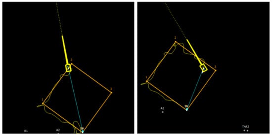
Figure 36.
Path following performed by professional ROV pilot in manual mode, with disabled FTC.
5. Conclusions
This paper presented a hybrid method for control allocation, able to allocate a feasible solution of the control allocation problem, optimal in sense, on the entire attainable command set in real-time. The paper provides a clear geometric interpretation of the underlying control allocation problem and deep insight into each step of the solution using a “virtual” ROV in low-dimensional control spaces. Then, the same concepts are extended to higher-dimensional cases, for open-frame ROV with four X-shaped (vectored) horizontal thrusters.
The hybrid method for control allocation is based on the integration of the weighted pseudoinverse and the fixed-point method. The weighted pseudoinverse method is a member of a family of generalised inverses and is the one that yields minimum control energy. The main disadvantage of the weighted pseudoinverse method is its inability to find the exact solution of the control allocation problem on the entire attainable command set, i.e., the feasible region for pseudoinverse is a subset of the attainable command set. In contrast, the fixed-point method can find the exact solution on the entire attainable command set. The price paid is the necessity to perform iterations at each program step. The number of iterations depends on design parameters and choice of initial iteration. The hybrid approach for control allocation originates from the integration of features of the weighted pseudoinverse and fixed-point method: the weighted psudoinverse method is used for cases when control inputs lie inside the feasible region for pseudoinverse, and the fixed-point method is used otherwise.
The performance of the thruster FTC system, whose main pillar is the hybrid method, has been evaluated not just in simulation, but in a real-world environment with observation-class ROV and work-class ROV through a series of complex, challenging subsea tasks in order to examine the performance of the FTC in fault-free and faulty conditions. Simulation results show that the FTC provides adequate reallocation in faulty situations, keeping all three DOF in the horizontal plane fully controllable, making it possible to control the motion of the faulty vehicle in a satisfactory way. Using different indicators and visualisation tools, the FTC can inform the ROV pilot about the position of actual command inputs relative to attainable command set. Using this information, even an inexperienced ROV pilot can detect the situation when thruster velocity saturation occurs and to correct the command inputs such that it becomes attainable. Results of real-world tests show that piloting of faulty ROV in pure manual mode was too hard task for a professional ROV pilot, i.e., disabling the faulty thruster without appropriate reallocation led to poor tracking performance and oscillatory character of yaw response during the way-point path following task. Execution of the same task with the FTC enabled led to a redistribution of available control energy among remaining operable thrusters, resulting in significant improvements in the global control performance of the vehicle in faulty situations.
Author Contributions
Conceptualization, E.O.; methodology, E.O. and D.T.; software, E.O. and P.T.; validation, M.R., A.K. and G.D., formal analysis, A.K.; investigation, P.T.; resources, A.W.; data curation, M.R.; writing—original draft preparation, E.O.; writing—review and editing, E.O., G.D. and D.T.; visualization, E.O.; supervision, D.T.; project administration, A.W.; funding acquisition, G.D. All authors have read and agreed to the published version of the manuscript.
Funding
This publication has emanated from research supported by the Science Foundation Ireland under the MaREI Centre research programme (Grant No. SFI/12/RC/2302, 15/RI/3232 and SFI/14/SP/2740) and LERO Science Foundation Ireland grant 13/RC/2094. It is also co-funded under the European Regional Development Fund through the Southern and Eastern Regional Operational Programme to Lero and MaREI centre. The development of ROV Latis and fault-tolerant control system has been supported by funding under the Irish Marine Institute and the Marine RTDI Measure, Productive Sector Operational Programme, National Development Plan 2000–2006 (PhD -05-004, INF-06-013 and IND-05-03); Science Foundation Ireland under Grant 06/CP/E007; HEA PRTLI 3 (MSR3.2 project -Deep Ocean Habitat Mapping using ROV; HEA PRTLI 4 Environment & Climate Change Impacts and Responses Project/ Environment Graduate Programme; an Enterprise Ireland Commercialisation Fund Technology Development 2007 projects—MPPT Ring (CFTD/07/IT/313, “Multi-Purpose Platform Technologies for Subsea Operations) and PULSE RT (CFTD/07/323, “Precision Underwater Accelerated Sonar Emulation in Real-Time) with ERDF funding.
Conflicts of Interest
The authors declare no conflict of interest.
References
- Blanke, M.; Kinnaert, M.; Lunze, J.; Staroswiecki, M. Diagnosis and Fault-Tolerant Control; Springer: Berlin/Heidelberg, Germany, 2006; ISBN-13 978-3-540-35652-3. [Google Scholar]
- Oppenheimer, M.; Doman, D.; Bolender, M. Control allocation. In The Control Handbook, Control System Applications, 2nd ed.; Levine, W.S., Ed.; CRC Press: Boca Raton, FL, USA, 2010; Chapter 8. [Google Scholar]
- Fossen, T.I.; Johansen, T.A. A survey of control allocation methods for ships and underwater vehicles. In Proceedings of the 14th Mediterranean Conference on Control and Automation, Ancona, Italy, 28–30 June 2006. [Google Scholar]
- Johansen, T.A.; Fossen, T.I. Control allocation—A survey. Automatica 2013, 49, 1087–1103. [Google Scholar] [CrossRef]
- Zhang, Y.; Zeng, J.; Li, Y.; Sun, Y.; Wan, L.; Huang, S. Research on reconstructive fault-tolerant control of an X-rudder AUV. In Proceedings of the OCEANS 2016 MTS/IEEE Monterey, Monterey, CA, USA, 19–23 September 2016. [Google Scholar]
- Chu, Z.; Luo, C.; Zhu, D. Adaptive fault-tolerant control for a class of remotely operated vehicles under thruster redundancy. In Proceedings of the IEEE 8th International Conference on Underwater System Technology: Theory and Applications (USYS), Wuhan, China, 1–3 December 2018. [Google Scholar] [CrossRef]
- Liu, X.; Zhang, M.; Yao, F. Adaptive fault-tolerant control and thruster fault reconstruction for an autonomous underwater vehicle. Ocean Eng. 2018, 155, 10–23. [Google Scholar] [CrossRef]
- Ropars, B.; Lasbouygues, A.; Lapierre, L.; Andreu, D. Thruster’s dead-zones compensation for the actuation system of an underwater vehicle. In Proceedings of the European Control Conference (ECC), Linz, Austria, 15–17 July 2015; pp. 741–746. [Google Scholar]
- Baldini, A.; Ciabattoni, L.; Felicetti, R.; Ferracuti, F.; Freddi, A.; and Monteriù, A. Dynamic surface fault-tolerant control for underwater remotely operated vehicles. ISA Trans. 2018, 78, 10–20. [Google Scholar] [CrossRef]
- Chin, C.S.; Lau, M.W.S.; Low, E.; Seet, G.G.L. Design of Thrusters Configuration and Thrust Allocation Control for a Remotely Operated Vehicle. In Proceedings of the IEEE Conference on Robotics, Automation and Mechatronics, Bangkok, Thailand, 1–3 June 2006. [Google Scholar] [CrossRef]
- De Carolis, V.; Maurelli, F.; Brown, K.E.; Lane, D.M. Energy-aware fault-mitigation architecture for underwater vehicles. Auton. Robot. 2017, 41, 1083–1105. [Google Scholar] [CrossRef]
- Davoodi, M.; Meskin, N.; Khorasani, K. Event-triggered fault estimation and accommodation design for linear systems. In Proceedings of the Second International Conference on Event-based Control, Communication, and Signal Processing (EBCCSP), Krakow, Poland, 13–15 June 2016. [Google Scholar]
- Karras, G.C.; Fourlas, G.K. Model Predictive Fault Tolerant Control for Omni-direct ional Mobile Robots. J. Intell. Robot. Syst. 2019. [Google Scholar] [CrossRef]
- Liu, H.; Wei, Y.; Zhou, X.; Li, G. Operated ROV Thrust Distribution Control System Based on Adaptive Back-stepping controller. In Proceedings of the 35th Chinese Control Conference, Chengdu, China, 27–29 July 2016. [Google Scholar]
- Antonelli, G.; Fossen, T.I.; Yoerger, D.R. Underwater Robotics. In Springer Handbook of Robotics; Siciliano, B., Khatib, O., Eds.; Springer: Berlin/Heidelberg, Germany, 2008; pp. 987–1008. [Google Scholar]
- Antonelli, G. Underwater Robots, 2nd ed.; STAR 2; Springer: Berlin/Heidelberg, Germany, 2006; pp. 79–91. [Google Scholar]
- Omerdic, E.; Roberts, G.N. Thruster fault diagnosis and accommodation for open-frame underwater vehicles. Control Eng. Pract. 2004, 12, 1575–1598. [Google Scholar] [CrossRef]
- Fossen, T.I. Handbook of Marine Craft Hydrodynamics and Motion Control; John Wiley & Sons: Hoboken, NJ, USA, 2011. [Google Scholar]
- Härkegârd, O. Backstepping and Control Allocation with Application to Flight Control. Ph.D. Thesis, Department of Electrical Engineering, Linköping University, Linköping, Sweden, 2003. [Google Scholar]
- Omerdic, E. Thruster Fault-Tolerant Control; VDM Verlag: Riga, Latvia, 2009; ISBN 978-3-639-11739-4. [Google Scholar]
- Bodson, M. Evaluation of Optimisation Methods for Control Allocation. J. Guid. Control Dyn. 2002, 25, 703–711. [Google Scholar] [CrossRef]
- Burken, J.; Lu, P.; Wu, Z.; Bahm, C. Two Reconfigurable Flight-Control Design Methods: Robust Servomechanism and Control Allocation. J. Guid. Control Dyn. 2001, 24, 482–493. [Google Scholar] [CrossRef]
- Omerdic, E.; Toal, D.; Nolan, S.; Ahmad, H. ROV LATIS: Next Generation Smart Underwater Vehicle. In IET Book: Further Advances in Unmanned Marine Vehicles; Inst of Engineering & Technology: London, UK, 2002; Chapter 2; ISBN-10 1849194793, ISBN-13 978-1849194792. [Google Scholar]
© 2020 by the authors. Licensee MDPI, Basel, Switzerland. This article is an open access article distributed under the terms and conditions of the Creative Commons Attribution (CC BY) license (http://creativecommons.org/licenses/by/4.0/).