1. Introduction
Cable-driven parallel robots (referred to as CDPR in this paper) are parallel robots where the end-effector is linked to the base platform by replacing traditional rigid links with cables. This provides significant advantages, for example, in speed, acceleration, and workspace as compared with traditional robots. The abovementioned features make CDPRs an attractive alternative to traditional parallel robots. Cable-suspended cameras are widely known and even commercially implemented as applications of CDPR [
1]. Moreover, many prototypes have been proposed in fields such as rehabilitation and home care [
2]. Besides their numerous advantages, CDPRs introduce an additional constraint to motion planning and control, since cables can only exert positive tension forces on the end-effector. This characteristic makes trajectory planning and control tasks very complex. Moreover, CDPRs are more difficult to brake as compared with traditional robots with rigid links [
3]. In fact, in traditional robots a hard stop of motors quickly leads to a full stop of the whole robot, while this cannot be applied to CDPRs since a hard stop of motors in CDPRs cannot prevent further motion of the flexible cables that allow motion in the robot end-effector. This makes it very difficult to create an emergency stop for CDPRs, while this feature would be very important from a safety point of view.
The failure of cables has hardly been addressed in the literature on cable-driven robots. An example can be found in [
4], where the authors investigated the possibility of removing a cable while maintaining a static equilibrium pose. In particular, the authors of [
4] proposed a method to identify the cables that are critical for ensuring the feasibility of a specific configuration. Then, the method finds out any unnecessary cable. In [
5] and further in [
6], Notash presented a possible classification of the feasible failure modes and introduced three methods to recover or compensate for a lost wrench of a redundant cable robot in static equilibrium conditions. In [
7] the authors suggest using an optimal design procedure for minimizing the differences in cable tensions. This approach can also be applied in the case of a cable failure.
A completely different approach is presented in [
8], where the authors propose a first method to control a moving end-effector after a cable failure. Such a strategy consists of generating a safe motion to a predetermined pose, while keeping the end-effector inside the workspace. The planning of such motion is based on pre-computed force limits and trajectories. A different approach was presented in [
9], where the end-effector reaches the safe position by following a planned oscillatory trajectory. Such a trajectory still allows us to achieve a positive and bounded tension in each cable.
This paper improves on the approach proposed in [
8] by proposing an efficient way to calculate and achieve a straight-line trajectory after failure, specifically for the case of the LAWEX robot [
10,
11]. This represents a first attempt to apply the Wrench Exertion Capability [
12,
13] as a tool to manage safety in cable-driven robots. It is important to note that this work is aiming at a preliminary feasibility study. Accordingly, only one type of cable failure has been considered, while other more complex cases will be considered as future work, with specific experimental validations with end users. The current work will preliminarily focus on the case of a single cable failure where the robot shape is preserved. In this case, even if the workspace keeps a shape similar to the original one, the configuration of the robot changes from an overconstrained to a suspended configuration. This change is very important, since a suspended CDPR must rely on gravity to maintain positive tension in all cables [
14]. Moreover, when the robot configuration changes due to failure, its performance in terms of force exertion capability decreases unpredictably and the planned motion can become unfeasible. Hence, it is important to have a control tool that can be used in real time to estimate the feasible wrench and identify which cable tensions are needed to stop the end-effector in case of cable failure. Future works will investigate the possibility of applying the Wrench Exertion Capability to more complex CDPRs, as in [
15].
The paper is organized as follows:
Section 2 provides a description of the design and the key operation characteristics of LAWEX;
Section 3 describes the proposed motion strategy in case of a cable failure;
Section 4 provides a description of the main characteristics of LAWEX in terms of workspace and forces;
Section 5 gives simulation results for the proposed motion strategy in case of one cable failure; finally,
Section 6 gives the conclusions.
2. Characteristics of LAWEX Robot
In the last decade, a research team led by the second author at LARM has been investigating several cable-driven parallel robot architectures within the European co-funded project AGEWELL, currently underway at Technical University of Cluj-Napoca, Romania. Specifically, this project aims to investigate novel devices and design solutions for limb rehabilitation tasks, as reported for example in [
10,
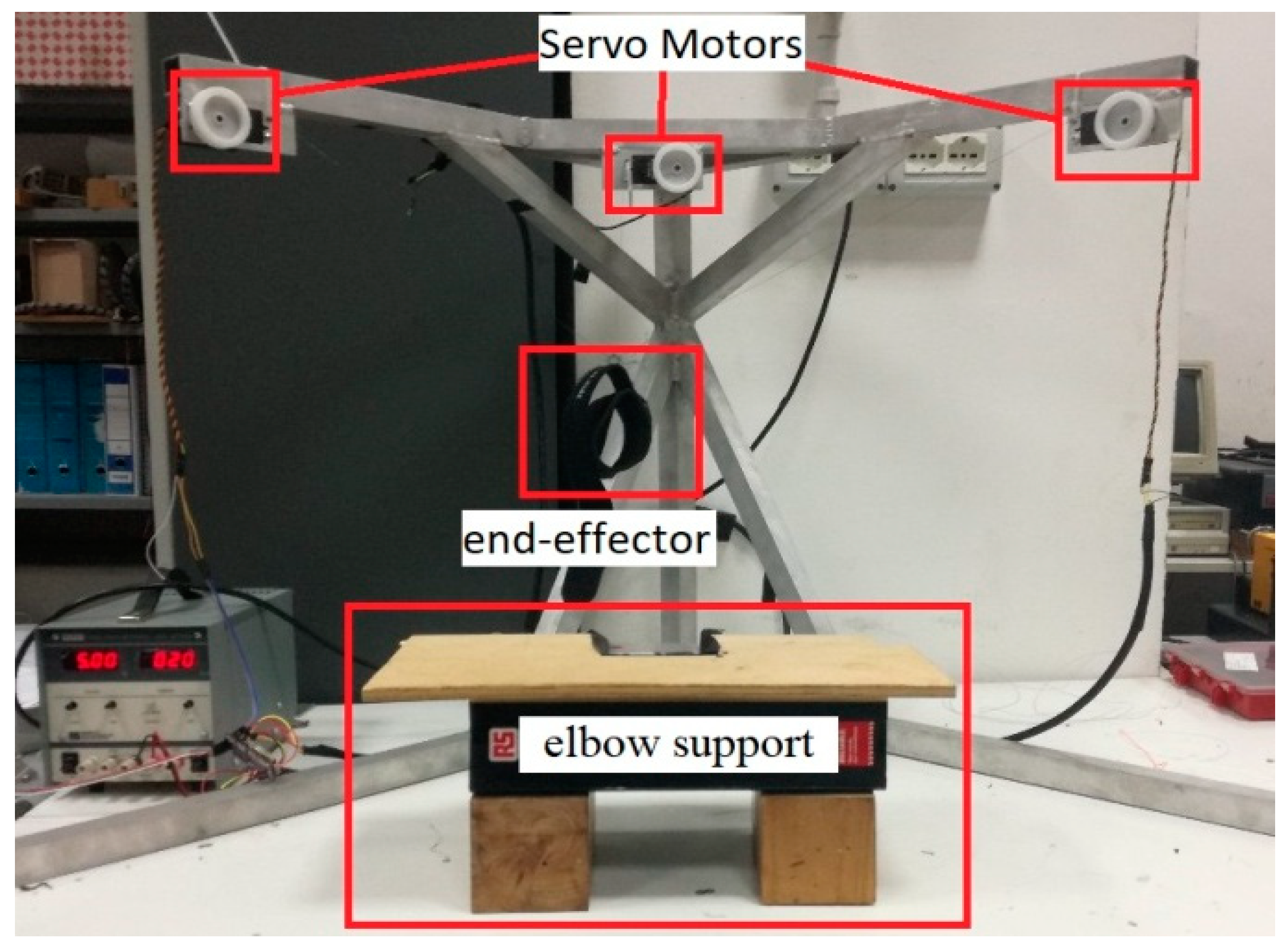
11]. Within this frame a novel cable-driven design solution has been proposed and built as shown in
Figure 1. The name of the prototype in
Figure 1 is LAWEX (LARM Wire-Driven EXercising device). Its design has been based on preliminary studies that have been carried out on human patients to determine the desired limb motions, such as reported in [
16,
17,
18,
19]. The main innovative aspect of LAWEX is its open architecture, which can allow easy accessibility by users during treatment, even if they are sitting in a wheelchair. Aluminum profiles are used for a lightweight and stiff design, while the robot structure can be easily assembled, stored, and moved so that it can be suitable even for home use.
The LAWEX robot includes four servo motors and four cables; the cables are connected to the end-effector through a wristband as shown in
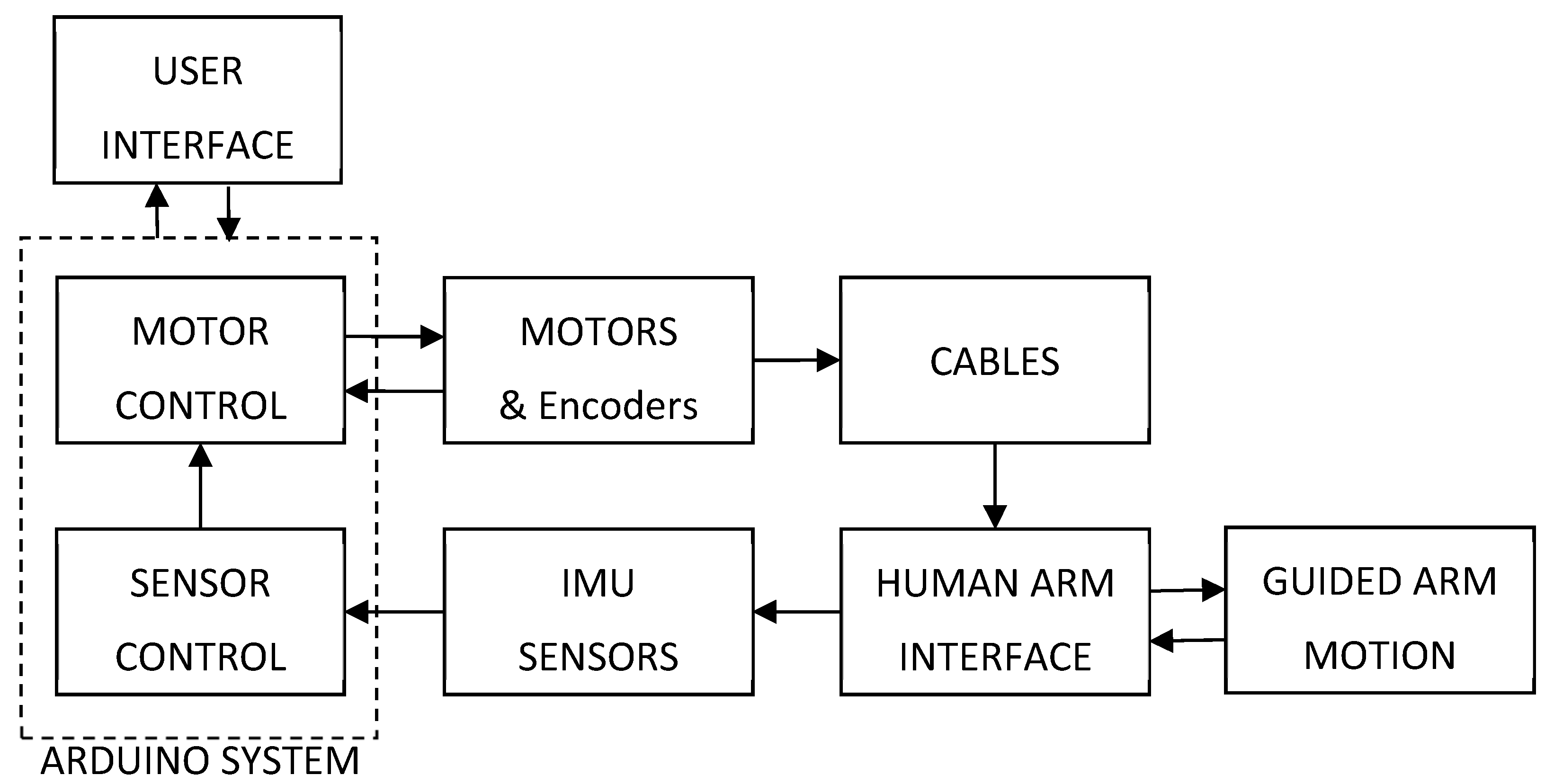
Figure 1. Moreover,
Figure 2 outlines an operation scheme of LAWEX. Namely, the human arm is attached to an interface/end-effector. This interface/end-effector is attached to a rigid frame by means of four cables. Each cable is connected to a servomotor that can change the cable length by using a winch. One of the servomotors is below the platform; the other three are attached to the upper part of the rigid frame. Cables are connected to the end-effector on the arm to be trained using a wristband. Further details on the end-effector are reported in [
17]. This setup allows several different motions that are suitable for limb exercises such as for rehabilitation purposes.
A successful rehabilitation procedure relies on several key aspects. In particular, it is necessary to define and complete a reliable and safe motion based on a proper training protocol. Accordingly, several experiments have been carried out to set up the proper motion parameters such as the elbow support position and arm motion ranges. Some tested setup conditions are shown in
Figure 1, where an elbow support keeps the elbow position fixed relative to LAWEX. This limits the arm motion to elbow flexion–extension.
2.1. Kinematics
The LAWEX frame structure has one servomotor in its bottom edge, where the fixed reference frame
is also located. Three other servomotors are attached on the upper part of the robot frame structure, one at the top edge and the other two at the top extremities of the structure, as also shown in
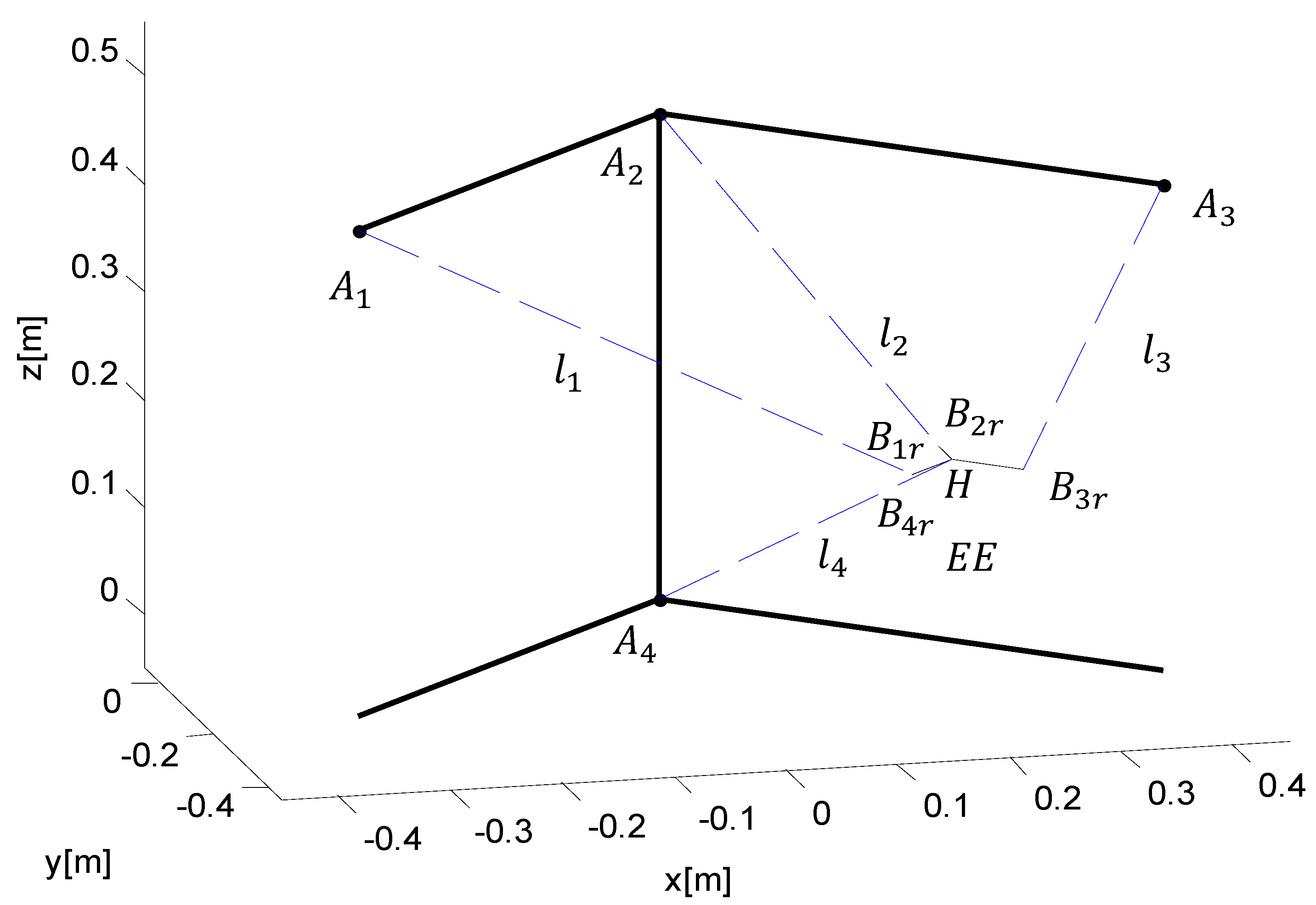
Figure 1. A kinematic scheme of LAWEX is shown in
Figure 3, which gives the location of cables. In this figure the starting points of cables are indicated by using the position vector
(
), where each starting point refers to the attachment of a cable to its pulley that is attached to the corresponding servomotor. Accordingly, one can write:
The pose of the end-effector EE in
Figure 3 is defined by the cable connection points
, (
), whose positions can be defined in reference to point H in the center of EE (this can also be defined as the mobile platform), such as:
If one assumes a fixed orientation of the moving platform during the robot operation, the absolute position of point
can be easily obtained by means of a loop-closure equation for the
i-th kinematic chain such as:
where
is the vector representing the
i-th cable of the robot. Therefore, considering Equation (3), one can write:
In this way it is possible to solve the inverse kinematics problem of the cable robot by computing the vector modules on both sides as:
The relationships between the cable lengths and the position of the point H on the EE can be expressed as:
2.2. Dynamics
If one neglects the elasticity of the cables, the length of each cable can be considered as directly proportional to the angular displacement
of the servomotors according to the relationship
where
is the total length of the cable,
is the driving pulley radio,
is the secondary pulley radio, and
is the distance between the centers of the pulleys. By isolating the term
, it is possible to obtain the actuation vector of the manipulator for computing the corresponding motion angle, which allows the actuators to reach the desired position.
The dynamic model of this manipulator can be described by
where
is the wrench vector that is represented by the three exerted forces
;
is the structure matrix that is made by the normal vectors
. Each vector
represents the direction that is connecting the end-effector with the
i-th pulley;
is the vector that contains the cable tensions
. The abovementioned mg represents the gravity force, which can be considered as equivalent to a vector with constant direction and constant modulus.
2.3. Programming the LAWEX Operation
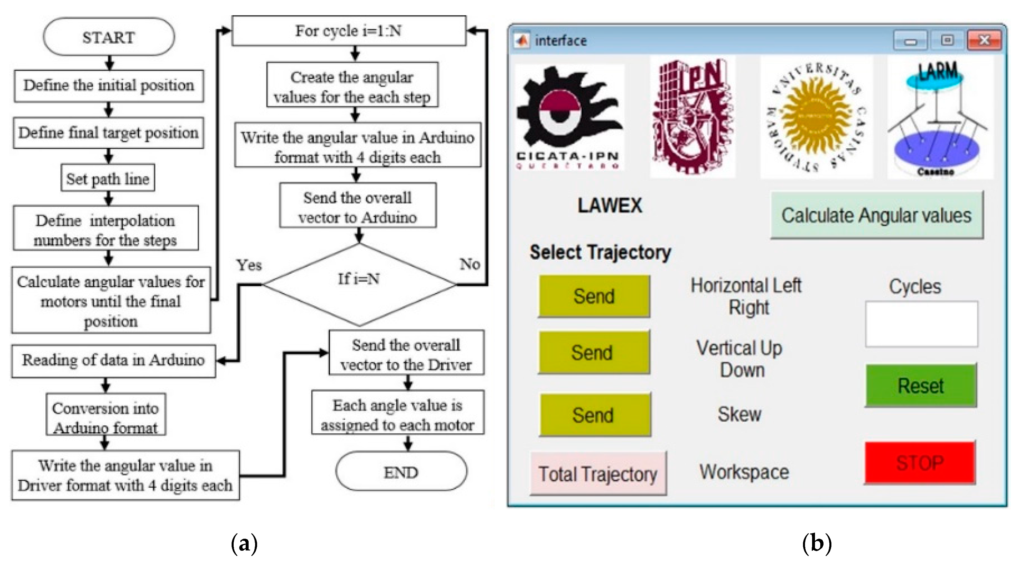
The programming of LAWEX has been developed according to
Figure 4. In particular,
Figure 4b shows a specifically developed user-friendly interface of LAWEX that runs in Java and can also be operated with Android smartphones. The user interface includes a button to perform the path planning. This is obtained by using the inverse kinematics of LAWEX, as discussed in the previous section and in [
13]. The obtained results of the inverse kinematics are the cable lengths versus time, with which we are able to generate the desired path of the end-effector. The computed cable lengths are then converted into the angular positions of the servomotors. This is done by considering that the rotation of each servomotor winds or unwinds its cable about its own winch. Each winch consists of a cylindrical drum of known diameter. Accordingly, each servomotor rotation generates a known increase or decrease of the cable length. The computed vector of angular positions versus time is sent to an Arduino board, which drives all four servomotors.
The path planning can be generated in real time for short motions or off-line for predefined motion paths such as horizontal motions from left to right and vice versa, vertical motions up and down and vice versa, or a skew (diagonal) motion combining the previous two pre-defined paths. The latter achieves up–down motion followed by left–right motion. For each of these predefined paths it is possible to set a desired number of cycles N so that the path is cyclically repeated N times. The button “calculate angular values” starts the calculations for path planning and sends the output vector of angular positions to the Arduino board. One can set other trajectories through the “total trajectory” button by setting up a list of the point coordinates one wishes to reach versus time.
If the system has a failure, one can push the reset button and the end-effector returns to its initial configuration, which means it is at top up configuration and centered. One can also push the stop button in an emergency.
3. Motion Strategy after Failure
The main goal of the proposed strategy is planning and achieving a motion for reaching a safe position after a cable failure. In this application, such a strategy takes into account the Wrench Exertion Capability (WEC) of the rehabilitation robot and allows the motors to exert a braking force in the opposite direction of motion. To make sure that the strategy works, the end-effector should also be inside the feasible workspace after the cable failure. In the proposed case, this condition is certainly respected when cable 4 breaks: indeed, when another cable breaks, the workspace can degenerate into a bidimensional shape and the motion of the end-effector cannot be easily controlled. It is worth noting that, during a therapy rehabilitation task, cable 4 can reach tensions higher than the other cables. Therefore, it might be advisable to increase the number of cables to distribute the corresponding load on more cables in a redundant setup.
The force that can be exerted in a specific direction, before and after the cable failure, can be computed by means of a performance index called Wrench Exertion Capability (WEC). As mentioned above, this index computes the maximum force (or torque) that can be exerted in a given direction while keeping all the other components null. This index can be used to compute the maximum exertable braking force in the direction of motion, aimed at stopping the end-effector. It is important to note that a specific reference frame should be defined in order to compute the WEC index. Such a reference frame should have an axis that lies along the direction of motion d. Accordingly, the braking force is computed by searching for the cable tensions that guarantee the maximum braking force along the direction of motion d by referring to the axis of the abovementioned reference frame. The following linear programming problem allows for achieving the proper cable tension:
where
is defined as the row of the Structure Matrix that refers to the direction of motion. Let us define as the rotation matrix that identifies the novel reference frame by means of the following relation: ;
is the matrix obtained by by removing the row ;
and are the vectors that define the range of the proper cable tensions;
identifies the broken cable, whose tension is set to a null value.
From a practical point of view, following a cable failure, a wise choice can be to reduce the value of the maximum allowed cable tension in order to reduce the risk of another cable failure. Therefore, in this application we assume the maximum allowed cable tension after failure to be reduced to 70% of the maximum allowed cable tension before failure so that .
An important issue that is related to optimization problems is that they are iterative and time-consuming. For this reason, their application in a real-time environment is discouraged and sometimes not applicable. This aspect is thus carefully considered to keep the computational costs within a feasible range for real-time implementation. Accordingly, the proposed case study considers a computationally efficient approach for computing the WEC index and the maximum allowed braking force as soon as a cable failure is detected. The chosen method for computing the WEC index has already been proposed in [
13]. It is based on a geometric representation of the forces that can be exerted. The main idea behind the algorithm is to consider the possible exertable wrenches as a polytope in the n-dimensional space (where n is the number of degrees of freedom). The n-dimensional space is represented so that the
x-axis is oriented with the direction of interest d. The intersections between the
x-axis and the skull of the wrench polytope represent the maximum and minimum exertable forces, respectively, in the direction of interest. The proposed algorithm also allows the corresponding tension configuration able to exert such forces. The corresponding tension vector is in the skull of the tension polytope in the m-dimensional case (where m is the number of cables). This algorithm allows for cutting 80% of the computational time compared with classic optimization-based algorithms.
4. Performance Analysis
This section reports a preliminary analysis of the performance (in terms of workspace and exertable force) of the cable robot before and after failure. The structure of the robot is described in
Section 2. Considering the sizes of LAWEX, parameters
,
are both set to 0.36 m;
is 0.46 m, while
can be neglected. For the performance analysis the origin of the fixed reference frame is attached to point
.
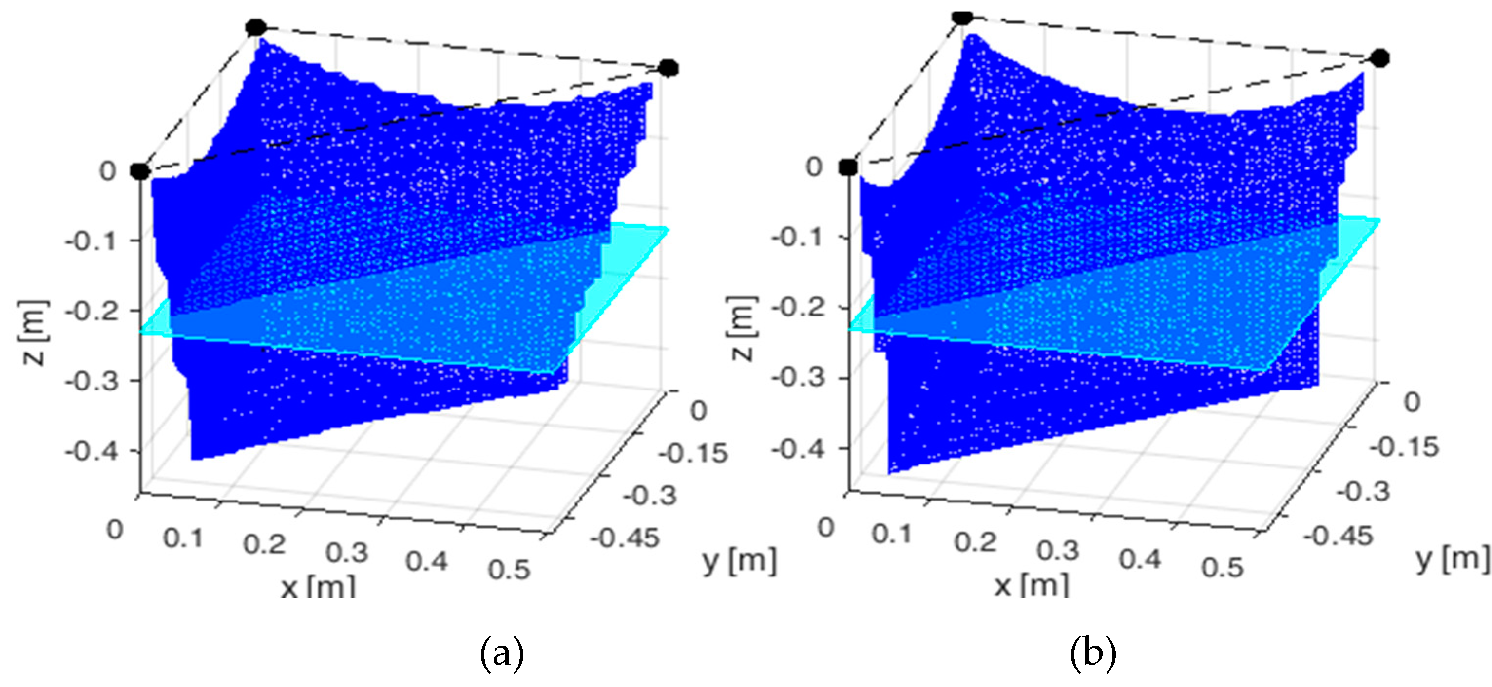
Figure 5 represents the static equilibrium workspace before and after failure.
Figure 5 is obtained by setting a minimum tension of 0.5 N and a maximum acceptable tension of 10 N as referring to the twisted iron cables of LAWEX. The mass of the end-effector is equal to 5 N (robot unload). On the other hand, the force exertion capability has been investigated by considering the directions of motion that the robot is supposed to have, i.e., left–right and up–down. The left–right motion in the considered reference frame results in a straight-line motion in the direction 45° in the plane x-y. The cyan rectangle in
Figure 5 represents the plane for which the performance regarding the right–left motion has been investigated. Simulations suggest that the best performance for this motion can be reached when z = −h/2.
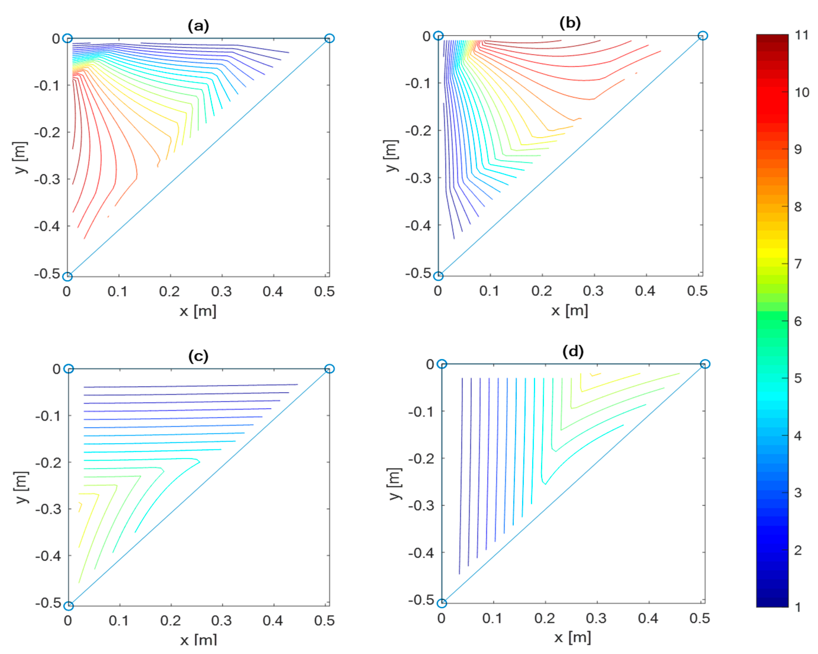
Figure 6 shows the computed maximum exertable force in the right direction (a–c) and in the left direction (b–d). This has been computed before (a–b) and after (c–d) the failure of the cable with a color indicating the force magnitude. The color scale in [N] is reported on the right side of
Figure 6. The shape of the polytope changes according to the position of the end-effector, since it is strictly related to the structure matrix
. It is important to note that only the tension polytope after failure is shown here, since it has a three-dimensional shape. Instead, the tension polytope before failure is a four-dimensional polytope that is not representable in a 3D plot.
5. Simulations
This section addresses the simulation of the behavior of LAWEX within its operation workspace. Discussion is also provided to clarify the main differences between the proposed approach and other previous approaches that are available in the literature, such as those reported in [
5,
6].
5.1. Simulation with Previous Approaches
Previous approaches are conceptually totally different from the proposed one as they aim to compensate for the lost wrench due to a cable failure by mostly considering the static equilibrium conditions.
A numerical simulation is reported to clarify the main features of the approaches in literature by referring to the case study of LAWEX. Namely, one can consider the LAWEX robot with the end-effector lying within its static feasible workspace. Without lack of generality, a feasible generic point P has been chosen with coordinates
. In this position the static equilibrium is guaranteed by the vector of cable tensions
that allows one to achieve a null wrench
in Equation (11) so that:
Since the robot is redundant, there are infinite tension vectors that satisfy Equation (14). In this case the solution with the minimum tension is chosen. Indeed, in this case one of the cables exerts the minimum allowed tension, 0.5 N, so that the vector of cable tensions is: .
If one considers the failure of one cable, its tension becomes zero. In case of failure of the fourth cable, its tension became null (
). The existing methods in the literature, such as [
5,
6], aim at achieving a new set of cable tensions that satisfies Equation (4) under the condition that one cable is no longer able to exert any force. Accordingly, one can compute the wrench vector
as follows:
In this case, the robot is no longer redundant, since one cable is considered broken. Accordingly, there is only one feasible tension vector that satisfies Equation (15) and vector can be computed as . This new tension vector allows for maintaining the static equilibrium of the end-effector after a cable failure.
5.2. Simulation of the Proposed Motion Strategy
The proposed approach differs totally from other existing methods, since it deals with a cable failure by planning a motion strategy under dynamic conditions, instead of addressing the static case as in existing methods. A numerical simulation is reported here to clarify the main features of the proposed novel approach by referring to the case study of LAWEX.
An algorithm has been written in Matlab-Simulink in order to prove its effectiveness. In a first test, a periodic motion from left to right has been considered. Such a motion has been defined by considering the center of the end effector starting at coordinates
and stopping its motion at coordinates
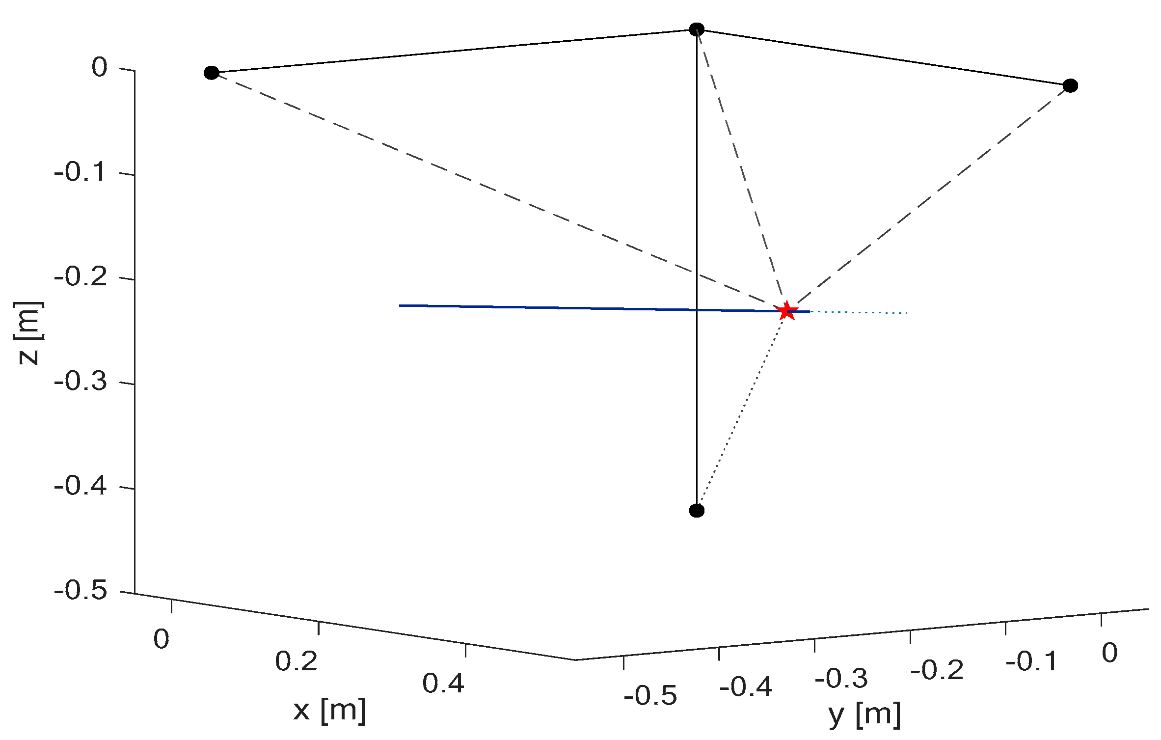
; the period of the full motion (roundtrip) requires about 2 s equally distributed in the forward motion (lasting one second) and the backward motion (lasting 1 s). We have considered a failure of cable 4 occurring at
s. In
Figure 7 the full motion performed by the end-effector is shown by a blue line, while the instant of failure is depicted in red.
Dashed lines in
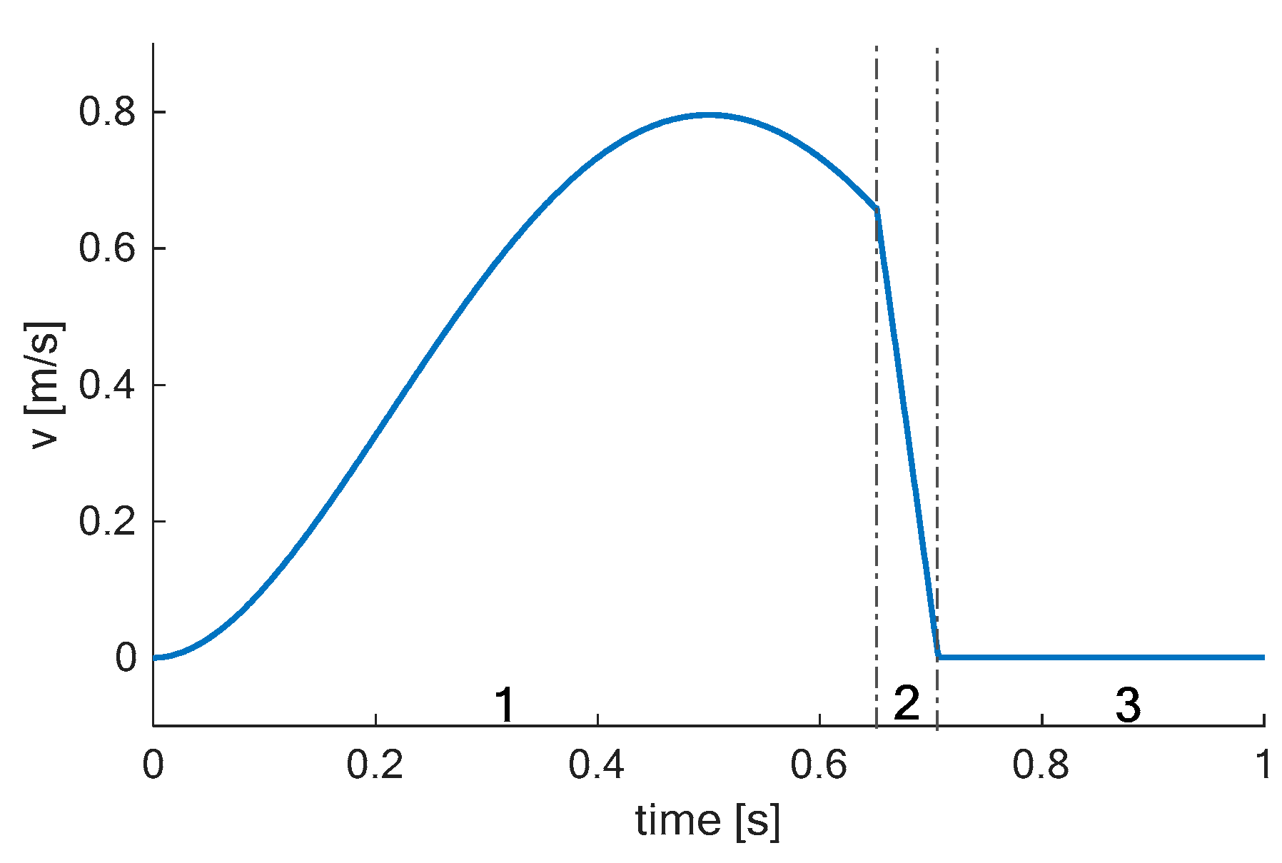
Figure 7 refer to cables that are still active after the failure of another cable. The damaged or broken cable has been highlighted with a dotted line. The absolute velocity of the whole path has been plotted in
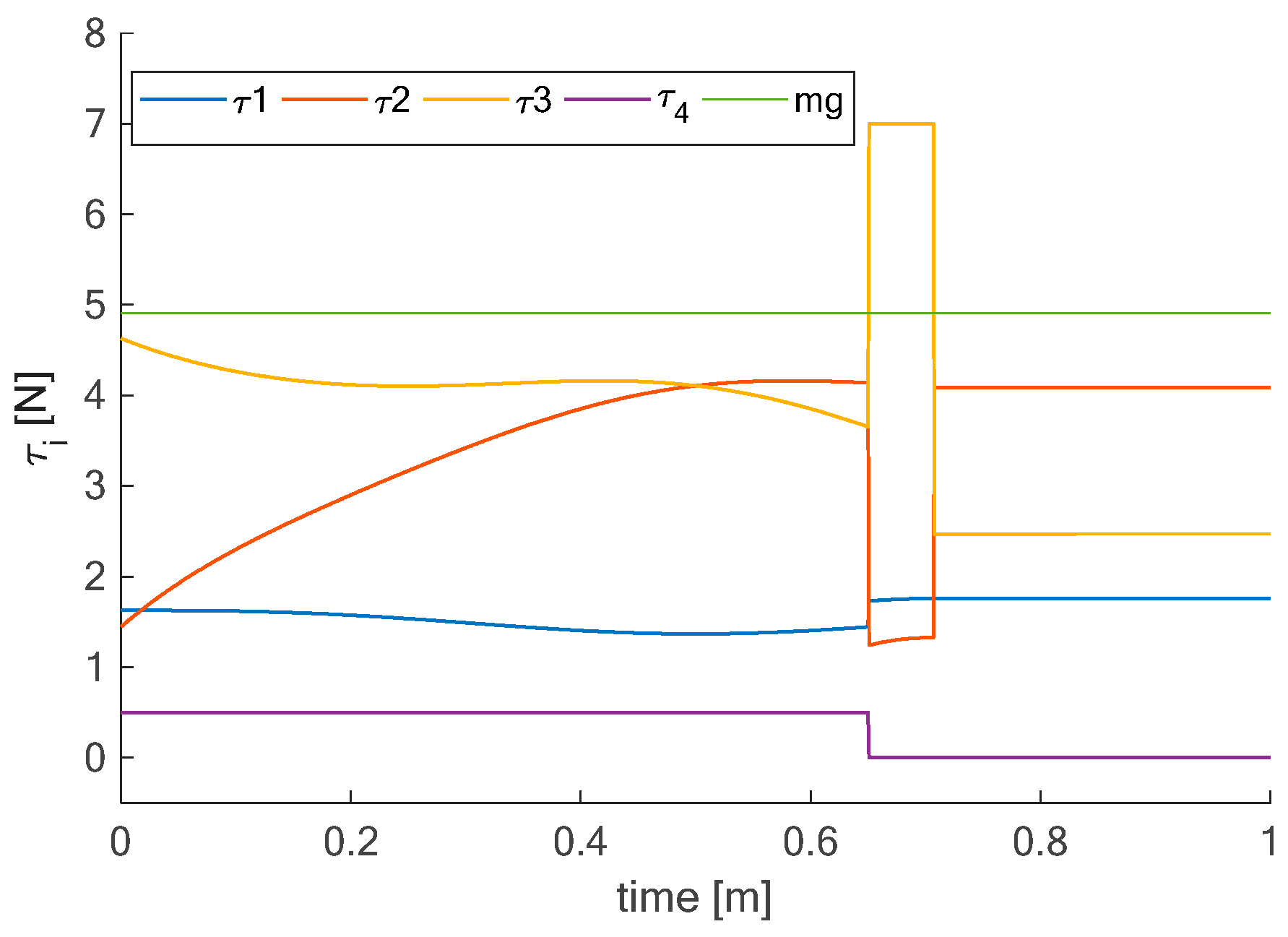
Figure 8 by showing the motion before the cable failure as phase 1 (from 0 to 0.65 s); the motion after cable failure as phase 2 (from 0.65 to 0.7 s); the reaching of final configuration as phase 3 (from 0.7 to 1 s). The tensions of the cables are depicted in
Figure 9. The time axis lasts 1 s in order to highlight the three different phases. During the first phase the end-effector is moving along the planned trajectory; in the second phase, after the cable failure, the proposed algorithm computes the cable tensions that are needed for exerting the braking force that is needed to stop the end-effector. The last phase begins when the velocity of the end-effector is close to zero. In this phase the cable tension reaches a static equilibrium configuration in the actual position.


