1. Introduction
Closed-chain mechanisms, particularly parallel mechanisms, are reputed to exhibit favorable characteristics with respect to their serial counterparts, mainly due to the possibility of distributing the load on the output member to several kinematic chains assembled in parallel and reducing moving inertia by locating the motors on or close to the fixed frame. Their potential advantages include: a larger payload to robot weight ratio, greater stiffness, better accuracy, and higher dynamic performance. Common drawbacks are a lower dexterity, a smaller workspace, complex kinematic geometry, and existence of singular configurations.
While the synthesis and optimization of translational parallel manipulators is a well understood problem that has been addressed in several works [
1,
2,
3], the conceptual design of orientational parallel mechanisms with a large rotation range remains a challenging task. In this article, the practical implementation of this class of mechanisms is considered for the wrist design of humanoid robots. The reference application here is the iCub, a 53DOF open-source humanoid robot developed to support research in embodied cognition [
4].
There has been significant research towards the design of robotic wrists over the years and the literature is rather large [
5,
6]. Early studies presented the use of a redundant spherical wrist with four converging revolute (R) joint serial chain; kinematically equivalent to a spherical joint [
7,
8]. A conceptual design to achieve unbounded joint motions by replacing the intermediate joint of a Euler-angle wrist with a four-bar linkage was proposed in [
9], but its practical implementations showed considerable restrictions on the workspace. The “standard” two-axis gimbal system tends to be one of the predominant choices for its wide range of decoupled yaw/pitch motions, fully isotropic workspace and a straightforward kinematics [
10,
11]. Since traditional layouts are not suitable for the iCub because of volume limitations, the implementation of an orientational parallel mechanism was brought into consideration for the robot’s wrist.
The humanoid robotics literature is rich of examples of 2DOF mechanisms with parallel kinematics, based on linear actuators; among these we can cite the wrist of the robot AILA [
12], the ankle of WABIAN-2RIII [
13] and the wrist of Roboray [
14]. Preliminary implementations showed that this class of mechanisms is not viable for the iCub wrist, mainly for the following three reasons: (i) the large volume occupied by the linear ball-screw stages, (ii) limited rotation range due to the mechanism’s self-collisions and iii) the presence of kinematic singularities in the workspace.
The focus was then shifted to a class of fully decoupled 2DOF PKMs that provide hemispherical workspace. Spherical linkage mechanisms such as the spherical five-bars [
15] and spherical six-bar mechanisms [
16,
17], have all the revolute joint axes intersecting at a common point, thus promising more uniform kinematic behavior.
Another one of the most prominent works, was the OmniWrist-III [
18] mechanism by
Ross-Hime Designs, Inc., which falls under the class of N-UU mechanism. Each limb of the mechanism comprises a pair of universal joints, which is mirror symmetric about a common plane [
19,
20]. In comparison to a single universal joint which is a Euler-angle mechanism, a N-UU mechanism works under the same principle of a homokinetic joint or coupling [
19,
21], and can be effectively analyzed using Lie group methods [
22,
23]. It is shown to have large workspace, hemispherical rotation capability, and slender form factor for the overall system.
Recently, Kim et al. reported on their implementation of the Quaternion joint [
24], a design similar to the one patented by Lande and David in 1978 [
25]. This has a 2 DOF joint emulating spherical pure rolling motion and is surrounded by two pairs of actuating wires, the motions of which directly correspond to the Quaternion values of the joint.
This article is further structured as follows:
Section 2 discusses various strategies of actuator relocation to reduce the motor power requirements. The iCub wrist mk.2 design is presented in
Section 3 and the desired design objectives are proposed in
Section 4.
Section 5 describes the computer-aided design (CAD) modeling and simulation of the selected mechanisms form the ones mentioned previously and
Section 6 illustrates the various couplings between the workspace features and the joint angles obtained from the simulations. The obtained analyses are further discussed in
Section 7 and concluded in
Section 8.
2. Actuator Relocation
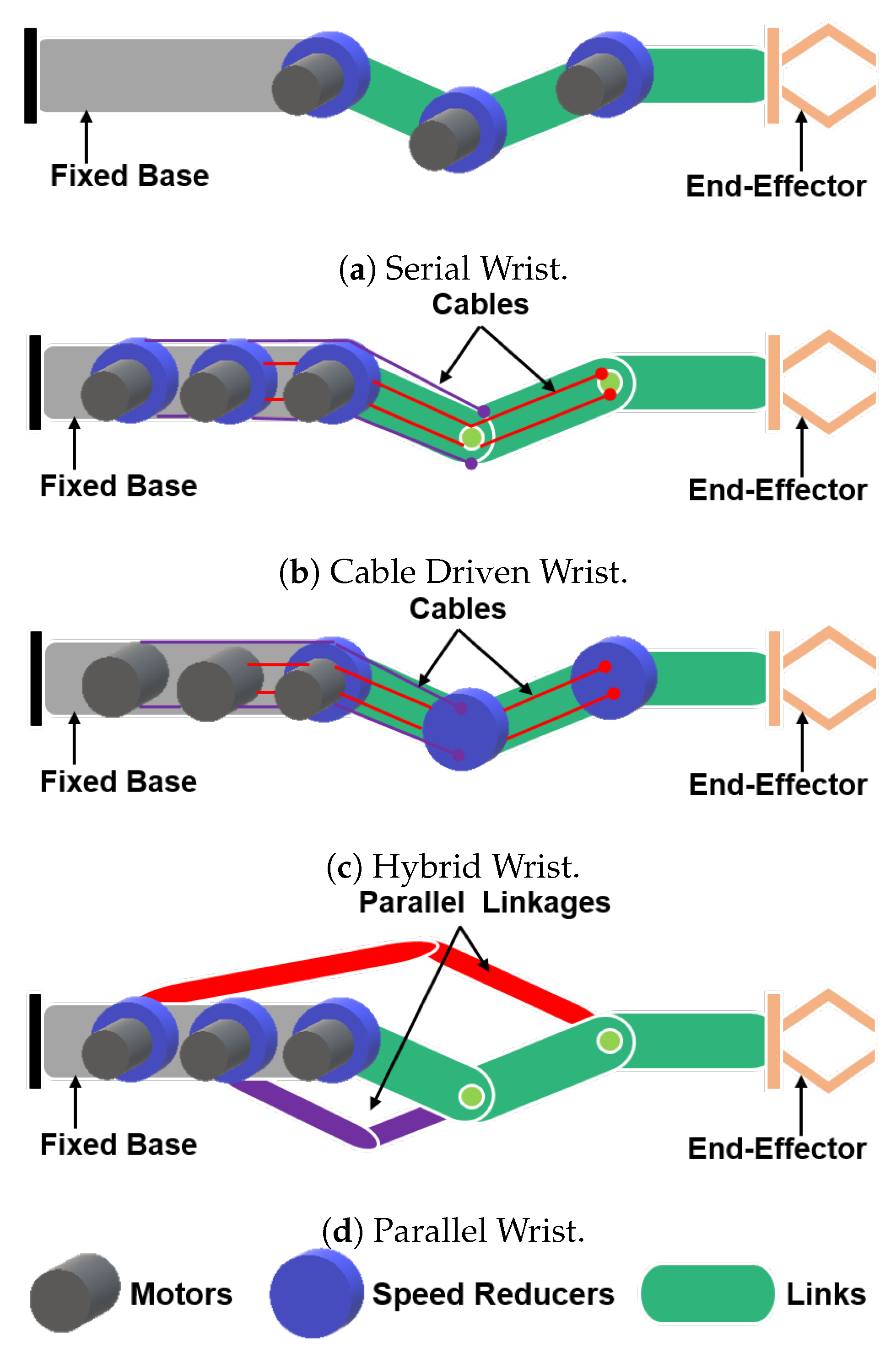
Most serial robotic manipulators comprise six or more DOF to provide complete control of the position in space and orientation of the end-effector. In most robots a functional distinction between the function of the DOF can be observed. The first three or four, most proximal DOF are generally employed to move the robot end-effector in space, while the distal DOF are used to orient the end-effector. The proximal and distal robot links and DOF are thus often loosely referred to as respectively the “arm” and “wrist” (
Figure 1a). Given their position, it is of the utmost importance for robotic wrists to be light-weight because distal masses increase the power requirements of proximal DOF. A possibility to overcome this shortcoming is to relocate the wrist actuators to more proximal locations. In electrically actuated robots (The current article focuses on electrically actuated robots since the vast majority of autonomous robots that have demonstrated practical capabilities are electrically actuated; similar considerations nevertheless hold for other actuation technologies like hydraulics), conceptually there are three main ways to achieve this goal. These approaches are illustrated in
Figure 1b–d where mechanisms are represented as planar for clarity.
The first one, represented in
Figure 1b is to place the motors fixed to the frame of previous links, and to convey the motive power to the wrist joints through a transmission system. Because of the complex rotations of wrist systems cable transmissions are generally adopted. This solution, for example, is employed in the wrist of the iCub robot (see
Section 3). A drawback of this solution is that the use of cables introduces elasticities which, in turn, complicates the accurate control of the system.
The second one, represented in
Figure 1c is to separate motors and speed-reducers, to keep the speed-reducers on the driven DOF, but to place the motors on proximal links and to connect them with fast, low force transmissions. Many authors have followed this approach; one of the first implementations, dating back to 1989, is the elbow mechanism of the Whole-Arm Manipulator (WAM) proposed by
Barrett Technologies and later developed by Townsend and Salisbury [
26]. More recent examples can be found in the work by Seok et al. [
27] and of Kim on the LIMS robot arm [
28].
The above two approaches will, however, inevitably increase the mechanical complexity of robots. Moreover, additional components are generally needed, which add to the total mass. Therefore, designers often face a delicate trade-off in striking a balance between adding masses (and complexity) for the transmissions, to reducing distal masses hence improving the functionality of a system. Also, these approaches are technically simpler in the case of planar motions. Unfortunately, most robots require non-planar joint arrangements.
A third alternative, represented in
Figure 1d, is to achieve mass relocation by combining adjacent joints into multi-DOF (degree of freedom) parallel kinematics mechanisms. Examples of this approach can be found in [
16,
18,
24,
29]. A typical characteristic of parallel mechanisms is that their kinematic behavior tends to be more complex, often “non-uniform” (see [
30,
31]) with respect to their serial counterparts. This complicates both the design and control of this type of mechanisms.
This work compares the kinematic behavior of four such parallel mechanisms with large and regular workspaces, with that of the iCub wrist mk.2 (belonging to the category of
Figure 1b) and the serial 2DOF gimbal mechanism (
Figure 1a category) that are considered as a reference. The analyses focused on mechanisms with rotational actuators as inputs, although the authors envision extending this work to cover mechanisms with linear actuators as inputs (e.g., see [
12,
32]).
3. iCub Wrist mk.2
The hand-forearm assembly of the iCub humanoid robot [
4], has 12 independent DOF, weighs 0.95 kg and has a volume of approximately 290 mm × 70 mm × 40 mm. These characteristics allow considerable dexterity, which comes, however, at the price of a limited robustness and great mechanical complexity. Significant amounts of efforts were devoted in recent years to improving the dependability of this sub-assembly, starting from the hand sub-system (e.g., see [
33]). The current article instead, shifts the focus to the wrist.
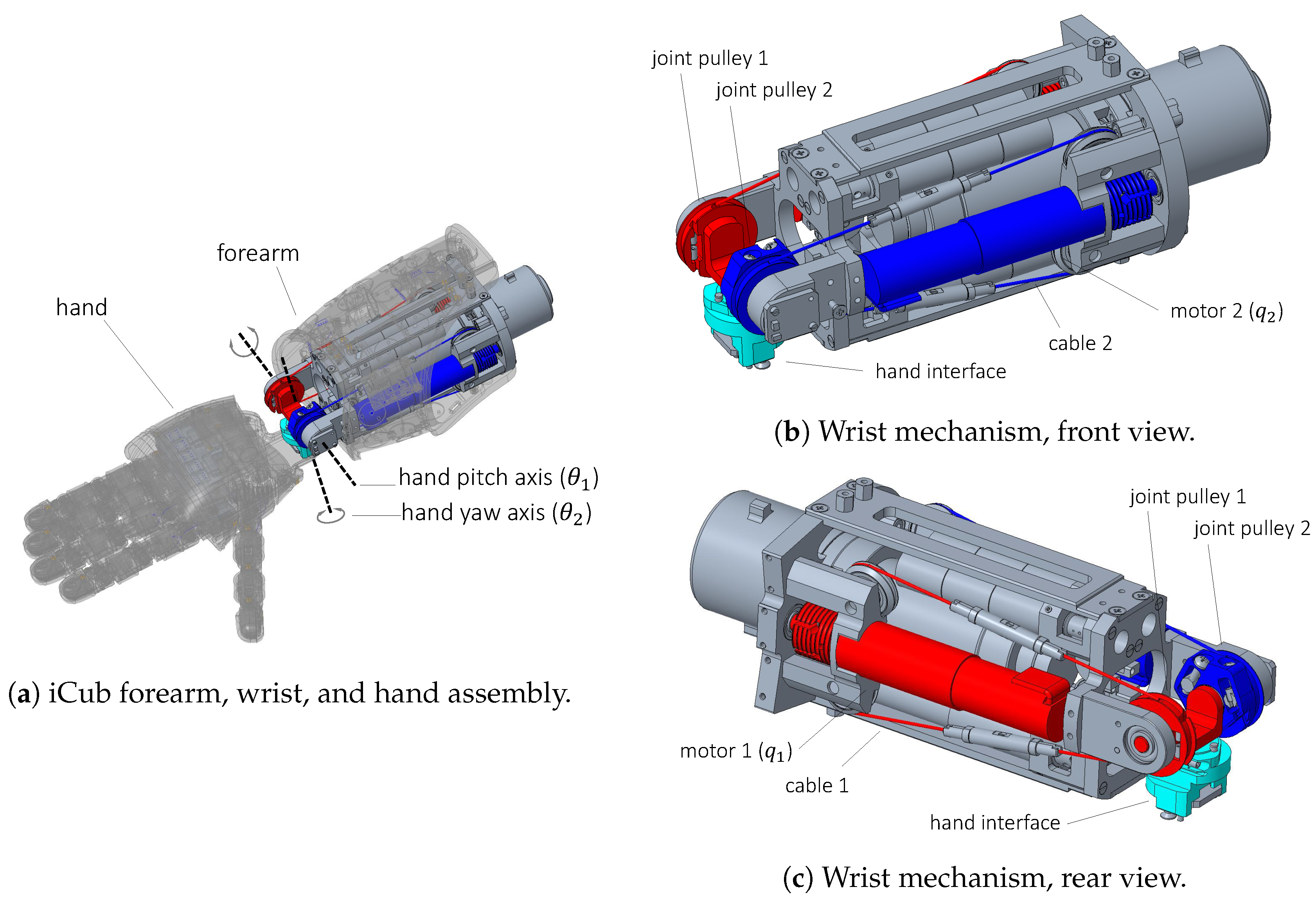
The iCub wrist mk.2 is a 2DOF cable driven mechanism, as shown in
Figure 2. The wrist is actuated by two Faulhaber 1331T012SR brushed DC motors, coupled to 159:1 planetary gear-heads that drive the pitch and yaw rotations of the hand. The motive power is transmitted by means of a cable-drive system (as represented in
Figure 2b,c). The motor pulley and the driven pulley have slightly different diameters resulting in a 1.38 transmission ratio.
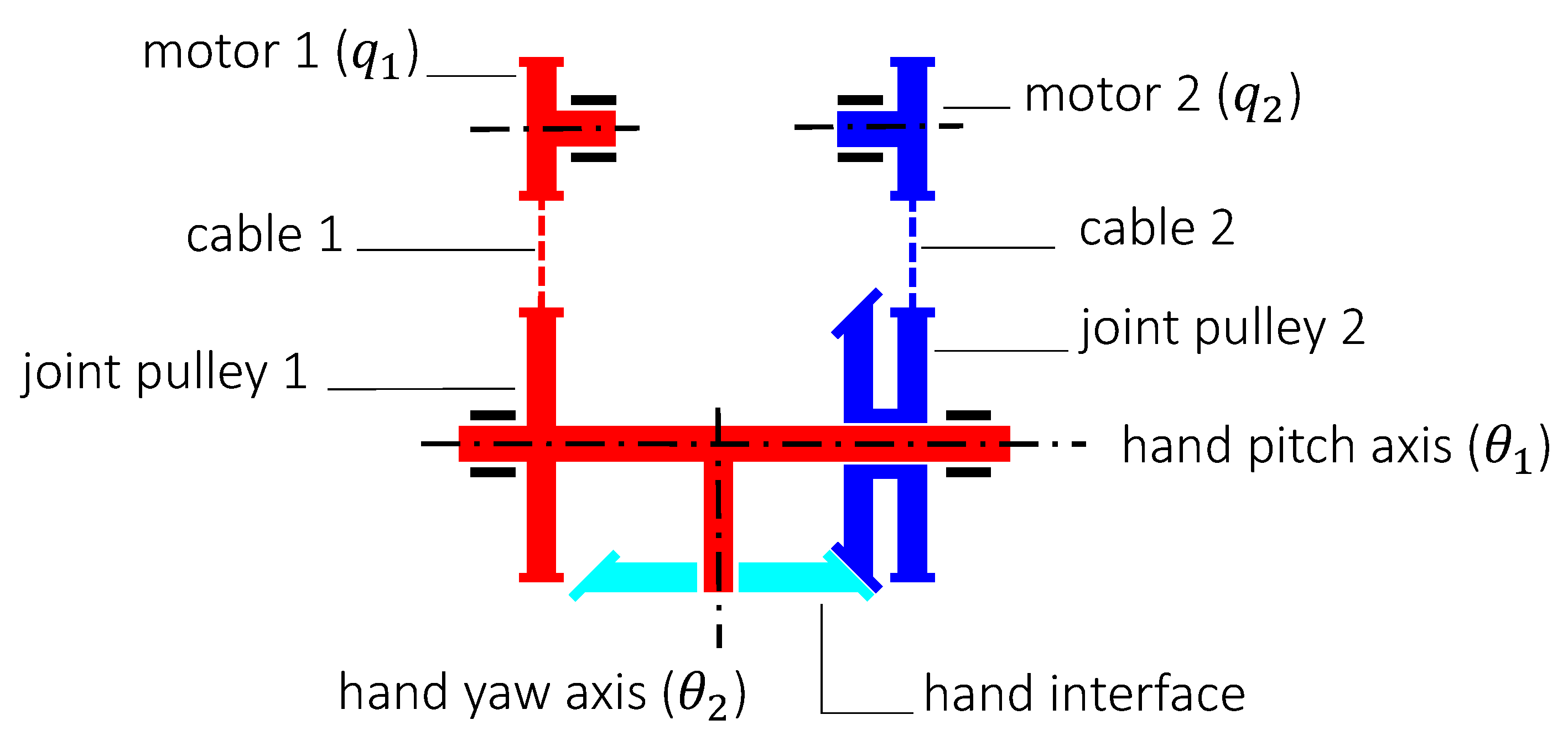
The motion of motor 2 is transmitted to the hand yaw joint with a secondary cable system which conveys motion to the hand interface (the cyan part in
Figure 2). This coupling is represented in the diagram of
Figure 3, and gives rise to the following relation between the motor positions
and hand orientations
:
The characteristics of the wrist mechanism are summarized in
Table 1.
4. Design Objectives
As mentioned in the previous sections a promising way to overcome the shortcomings of the current iCub mk.2 wrist implementation is to consider a new wrist design, to improve robustness, and dependability. Furthermore, the elasticity of the current cable-drive system is detrimental for the control of the system and should be eliminated of possible.
Alternative wrist implementations should improve upon the baseline defined by
Table 1, while fulfilling the following design criteria:
2 DOF: The mechanism shall possess two DOF (e.g., a pitch and yaw motion along the two Cartesian axes). The 3rd DOF for the wrist (roll) is obtained at the level of the elbow of the robot and its mechanics are housed within the forearm. The wrist roll is not considered in the current analysis.
Large Range of Motion (ROM): The mechanism shall possess a full hemispherical workspace, that is, a range of motion, possibly in the order of ° for each of the DOF.
Singularity-Free: The workspace of the mechanism should be free of singularities, thus allowing a highly uniform or isotropic behavior of the mechanism throughout the workspace.
Full Decoupling: An important feature for the mechanism is to have a decoupled motion, i.e., that the motion of one actuator results in the motion of one DOF independently from of the other, thus simplifying controller synthesis.
High Isotropy: The Jacobian matrix for the mechanism should be constant and equal to identity throughout the workspace to allow easier control implementations.
Compact Design: The maximum volume occupied by the wrist sub-assembly should be compact enough and compatible with the current hand-forearm assembly of the iCub humanoid, thus allowing easy integration of the new wrist into the system. The available volume can be approximated as a truncated cone with top and base diameters of 70 mm and 50 mm respectively and a height of 150 mm.
High Payload-to-Weight Ratio: The moving mass of the mechanism must be minimized (or relocated in the proximal part) to allow manipulation of heavier payload with limited motor power/torque.
The current study presents the analyses of the 2DOF gimbal mechanism and the iCub mk.2 wrist mechanisms that are presented, for reference, as benchmarks. Besides these mechanisms, four alternative parallel mechanisms are considered:
a spherical parallel mechanism with five curved links (bars) adapted from the one presented in [
15];
a spherical six bar mechanism as proposed in [
16]
an implementation of a N-UU parallel mechanisms similar to the OmniWrist-III mechanism [
18] developed by
Ross-Hime Designs, Inc.;
a Quaternion joint, similar to the N-UU class, as proposed by Kim in [
24] for the LIMS2-AMBIDEX robot.
5. CAD Modeling and Simulation
One of the drawbacks with the PKMs is that their kinematic relations are intricate and obtaining closed-form analytical solutions is rather complex. Thus, a CAD approach was followed to expedite the modeling and analysis process of the mechanisms. For each of the candidate mechanism, a CAD model of the kinematic architecture was developed using PTC Creo Parametric 4.0 and its Mechanism multi-body module. The workspace of the mechanisms was spanned by considering a mesh grid of all actuator input combinations within their admissible range. During the simulation, the in-built solvers from Creo compute the forward/inverse kinematics of the mechanism based on the modeled CAD structure for each of the input grid points. The simulation fails in case of any singularities and the does not produce a result for respective grid point. The resulting platform coordinates and orientation angles for the corresponding grid points were recorded from the simulation and later extracted for the analyses.
Indeed, the CAD-based method proved to be extremely convenient for rapidly assessing the workspace properties of the mechanism. Also, the CAD-based analysis can be very helpful in visualizing and detecting possible collisions and thus accelerating the overall design process.
To have a homogenized form factor for the mechanisms, based on the design objectives, all mechanism dimensions have been scaled to obtain a unit distance from the origin to the end-effector. This allows the workspace features of the mechanisms to be represented in an adimensional fashion. Consequently, in the following subsections, lengths will not be associated with their natural measurement units.
5.1. Gimbal
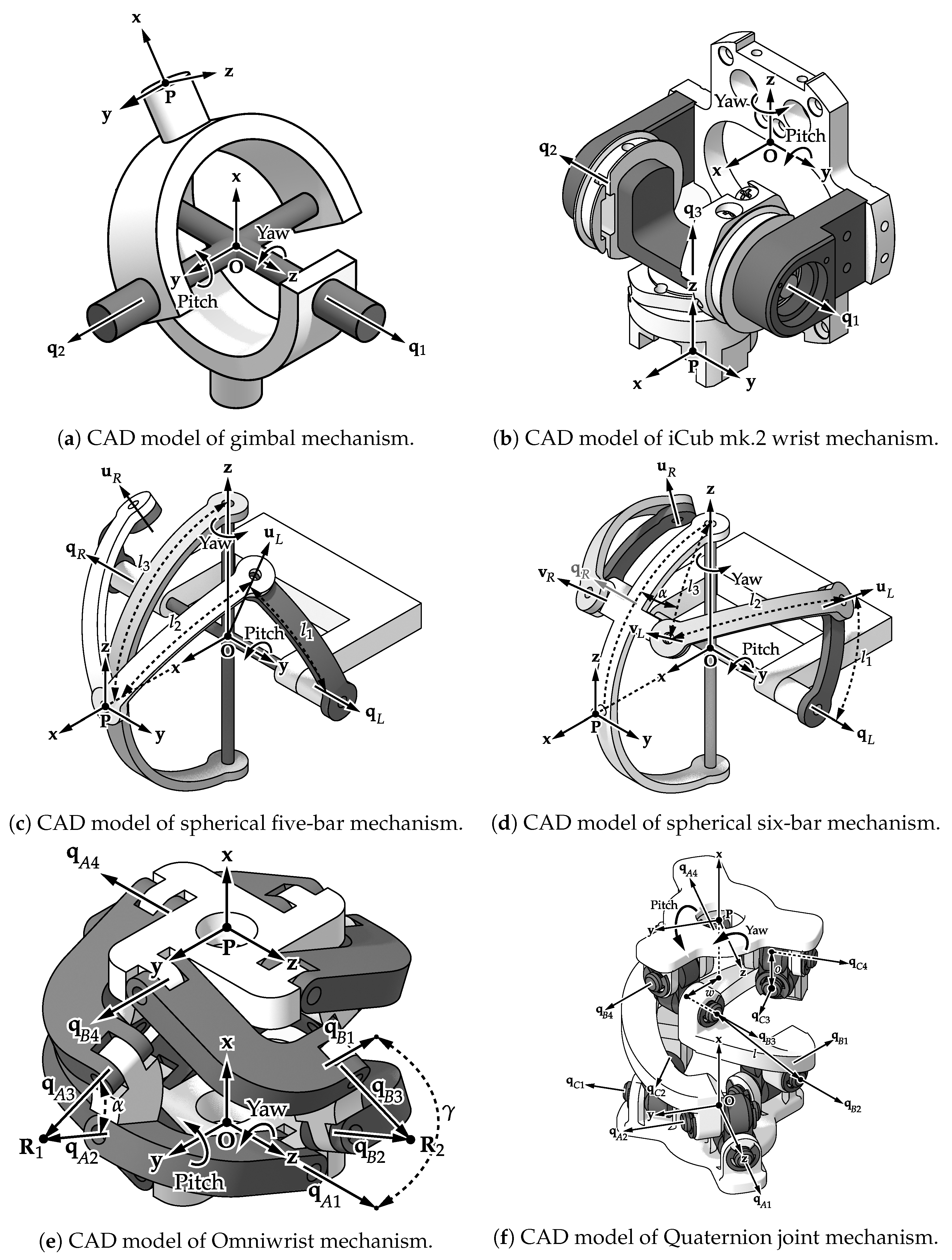
The 2DOF gimbal mechanism is a standard serial chain mechanism with two revolute joint axes successively placed along the two Cartesian axes, as shown in
Figure 4a. The axes of the two actuators
and
lie along the Z-axis and Y-axis respectively, of the base frame attached to the fixed point
O and result in the yaw and pitch motions.
5.2. iCub mk.2 Wrist
The structure of the iCub mk.2 wrist (
Figure 4b) was described in detail in
Section 3. The pitch and yaw motions are along the Y-axis and Z-axis, respectively.
5.3. Spherical Five-Bar Linkage
The spherical five-bar mechanism has a kinematic chain of five revolute joints connected with curved linkages.
Figure 4c shows a CAD model for this mechanism. All the axes of the mechanism intersect at the common central point
O and the mechanism is symmetric with regard to the XZ-plane. The two actuation joints are attached diametrically opposite to the fixed base, and are indicated as
and
in
Figure 4c. The joints
and
are passive. The end-effector point
P undergoes pitch and yaw motions about the Y-axis and Z-axis respectively of the base frame attached to the fixed point
O. It should be noted here that the mechanism has an additional constraint limb with a passive gimbal to restrict the parasitic roll motion of the end-effector. However, for simplicity, within this work the mechanism is referred to as a ’spherical five-bar mechanism’.
The parameter
represents the angle between the Y-axis and the line along the joint
, parameter
represents the angle between the line along
and the end-effector point
P and the parameter
represents the angle between the Z-axis and the end-effector point
P. Starting from the geometric parameters proposed by the respective authors [
15], the values were tweaked to suit the current application and were set to be
°,
° and
°.
5.4. Spherical Six-Bar Linkage
The spherical six-bar mechanism is a spherical mechanism composed of six revolute joints and interconnected with curved links [
16,
17]; its CAD model is represented in
Figure 4d. Similar to the spherical five-bar, the ’spherical six-bar mechanism’, also has the additional constraint limb with a passive gimbal and it follows the similar nomenclature for the joint axes and frames. All the axes of the mechanism intersect at the common central point
O and the mechanism is symmetric with regard to the XZ-plane. The actuated joints are
and
and the passive joints here are
,
,
and
. The pitch and yaw motions are along the Y-axis and Z-axis, respectively.
The parameter
represents the angle between the Y-axis and the line along the joint
, parameter
represents the angle between the lines joining
and
,
corresponds to the angle between the line joining
and the Z-axis and the additional parameter
here, corresponds to the angle between
and the XZ-plane. The parameter values were set to an optimal solution computed by differential evolution as proposed in [
17];
°,
°,
°, and
°.
5.5. OmniWrist-III (4-UU)
The OmniWrist-III mechanism is an N-UU type PKM with a moving platform connected to a fixed base through three or four identical limbs, each comprising of a serial chain of four non-coplanar revolute joints (RRRR) or equivalently two universal joints (UU).
Figure 4e represents the CAD model for the 4-UU mechanism with joint angles
,
limbs and
joints. The axes of rotation of the first two joints of each limb intersect at point
O, the center of the fixed base. The axes of rotation of the last two joints intersect at the center
P of the moving platform. The axes of rotation of the middle two joints of each limb also intersect in points
equidistant to the centers of the both base and the platform [
20]. The mechanism can be actuated using the first joints of any two adjacent limbs, in this case,
and
being the actuated ones.
The system geometry is defined by the geometric parameters
and
. The parameter
is the angle between the middle joints for each limb, that is, axis 2/axis 3 for all the limbs. The parameter
represents the angular offset between two adjacent limbs; in the hypothesis of equally spaced “limbs” this parameter also defines the total number of limbs in the system. The lengths
,
and
are translational offsets in the defined coordinate frames. The L-shaped link of the limb has a geometry of,
. Also,
can be expressed as a function of
and
as
. Parameters
,
and
, were scaled in order to obtain a unit distance from the center of the moving platform (point
P) to the center of the mechanism base (point
O). The parameter values of
° and
°, which are the ones normally employed for N-UU mechanisms with 4 limbs (4-UU) [
18], were chosen for this study. Given
,
and a unit
distance the values of
,
and
and their ratios were univocally determined.
5.6. Quaternion Joint
Figure 4f shows a CAD model for a “Quaternion joint” mechanism as proposed in [
24], and based on [
25]. This mechanism has a kinematic architecture of three identical limbs of two universal joints (equivalent to RRRR chains) and the joint angles
,
limbs and
joints. This arrangement achieves a structure similar to a three-dimensional anti-parallelogram. The two universal joints of each limb are diagonally attached to the fixed base and the moving platform such that the outer axes are parallel. Also, the two axes of each universal joint have an offset.
The system geometry is fully determined with three parameters: l, o, and w. The parameter l corresponds to the diagonal distance between inner axes of the universal joints of each limb. The parameter o represents the offset between the axes of the universal joint. The parameter w signifies the radial distance of the outer joint axes from the origin of the fixed frame O. These parameters are set to be , and . These values are proportional to the ones set by the proposing authors, but allow normalizing the size of the mechanism by setting the platform to base distance equal to 1.
It should be noted here that this mechanism proposes to only approximate the ideal spherical rolling motion, but with a very high accuracy (again see [
24] for details). This error, however small, still exceeds the tolerance limits allowed by the CAD simulation tools. Thus, only for this mechanism, the authors followed an inverse kinematic approach to solve for the joint angles by minimizing the error.
5.7. Orientation Parametrization
The first four mechanisms (i.e., the 2DOF gimbal, the iCub mk.2 wrist, the five-bar mechanism and the six-bar mechanism) have an inherent gimbal-like structure. In this case, it becomes natural to choose the Roll-Pitch-Yaw Euler-angle parameterization for the platform orientations as it implies a straightforward geometric interpretation. Since the mechanisms presented in this study are 2DOF, the pitch and yaw angles were considered in the analyses while the roll for these mechanisms is always equal to zero.
Instead for the Omniwrist and the Quaternion joint mechanisms, the Tilt-and-Torsion (T & T) parameterization as proposed by Bonev et al. [
34] was selected. These mechanisms fall under the class of zero-torsion mechanisms; in this case, the T&T angles yield a compact and very intuitive representation of the orientation workspace. For these mechanisms only the azimuth and tilt angles were considered in the analyses.
6. Workspace Analysis
To compare the previously presented mechanisms, the end-effector positions and orientations recorded from the CAD simulations were analyzed. The end-effector positions correspond to the Cartesian coordinates of point P with respect to the base frame attached to the fixed point O. The orientation parameterization is chosen with respect to the mechanism and is as described previously. The following subsections present the results of the CAD simulations.
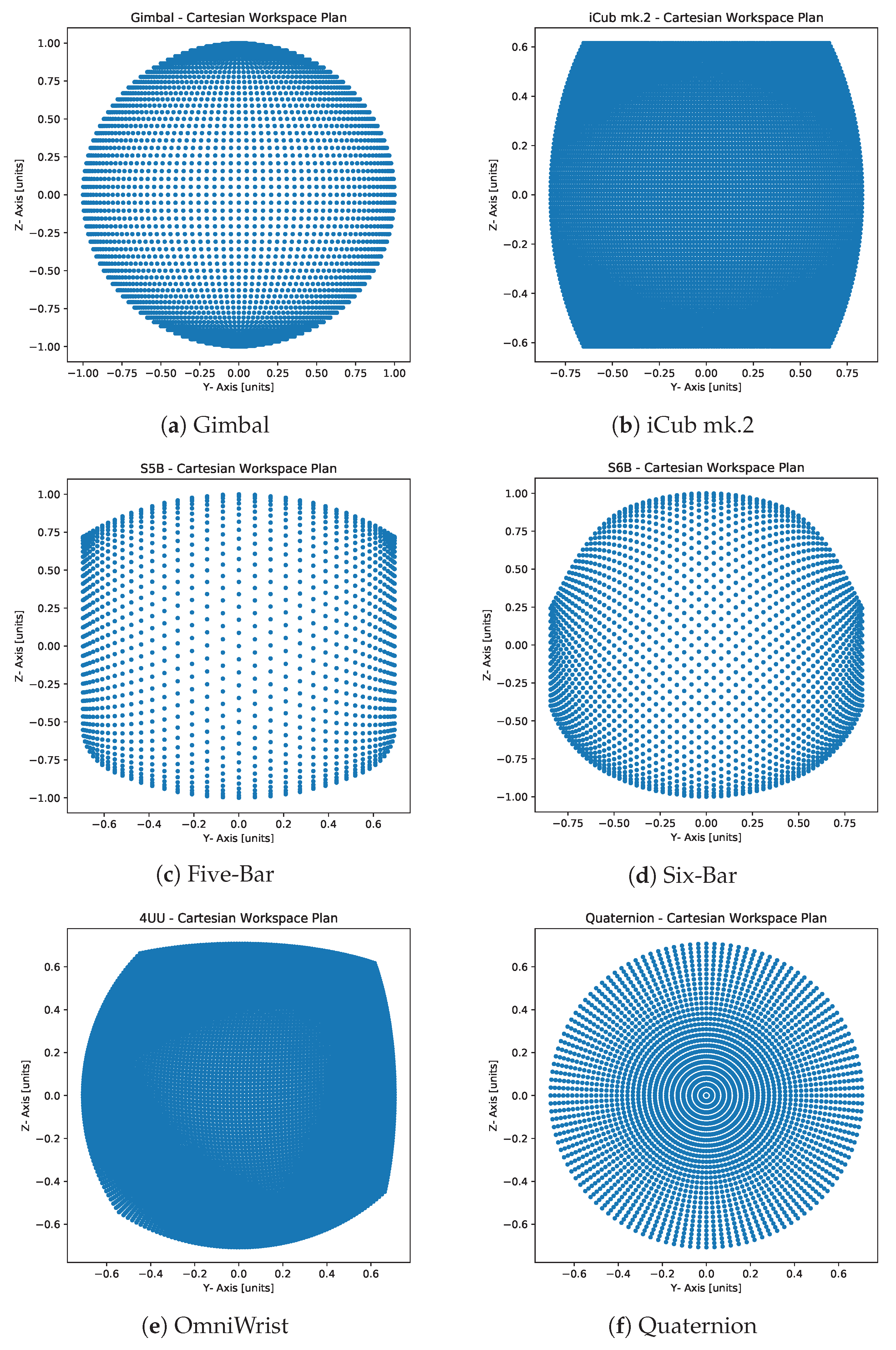
6.1. Normalized Cartesian Workspace
The
Figure 5 show the
plot representing the top view of the normalized Cartesian workspace for each mechanism. The plot for gimbal mechanism (
Figure 5a) shows a perfect circle, signifying a full hemispherical workspace. In the case of the iCub mk.2 wrist, the hardware limitations result in a truncated section of a hemisphere (
Figure 5b). The Quaternion joint mechanism also has a full hemispherical workspace (
Figure 5f). However, for the other three cases, the Cartesian workspace is only a partial hemisphere. Interestingly, the top view of the workspace of the Omniwrist mechanism (
Figure 5e) shows its boundaries are not symmetric with respect to the zero-abscissa and zero-ordinate axes, as reported in [
30].
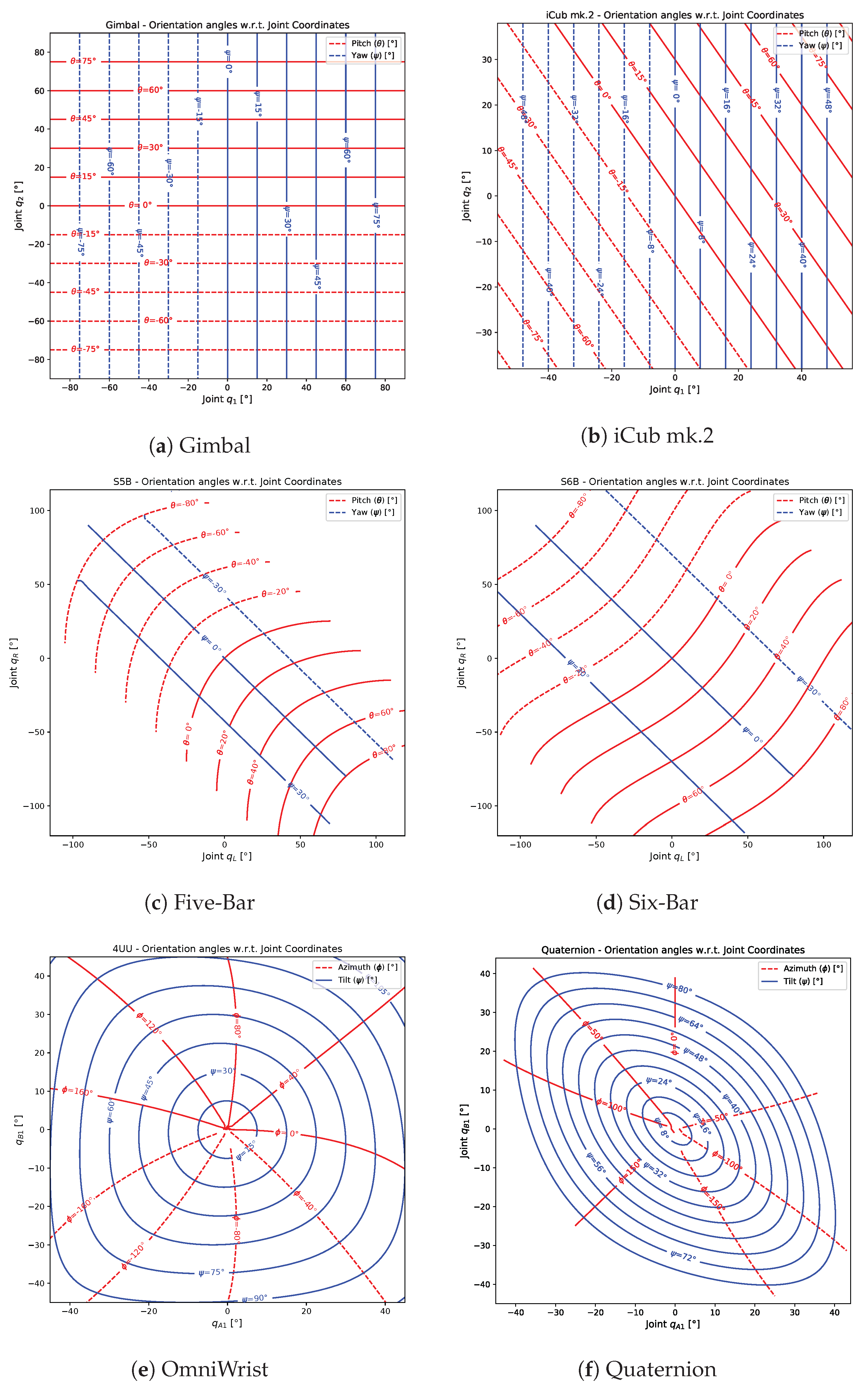
6.2. Orientation Angles with Regard to Joint Coordinates
The
Figure 6 show the
contour mapping of the orientation angles (pitch and yaw or the azimuth and tilt angles for the respective cases) with respect to the actuator joint coordinates. These plots show the direct mapping of desired output against the input and gives a fair idea about the complexity of control law necessary for the system. A perfectly square grid for this plot, implies that the two DOF are fully decoupled, as in the case of gimbal (
Figure 6a). Each of the actuator contributes exactly to 1 DOF. For the case of iCub mk.2 wrist, the yaw motion is fully decoupled whereas the pure pitch motion is dependent on both the motors (
Figure 6b). For the spherical five-bars and six-bars mechanisms, the two actuators when opposite, produce a pure yaw (diagonal blue lines) and when equal produce a pure pitch (red curves). The empty spaces in the corners, result due to the failure of simulation, possibly due to singularities. Both these mechanisms achieve a very high range of motion for pitch (
°), whereas that for yaw is restricted up to
° for five-bar (
Figure 6c) and up to
° for the six-bar (
Figure 6d). Both the Omniwrist and the Quaternion mechanisms (
Figure 6e,f), achieve a full tilt (90°) for all values of azimuth angle
. However, a peculiar “warping” (asymmetry) behavior is observed in case of the Omniwrist mechanism, as described in the previous work of the authors [
30].
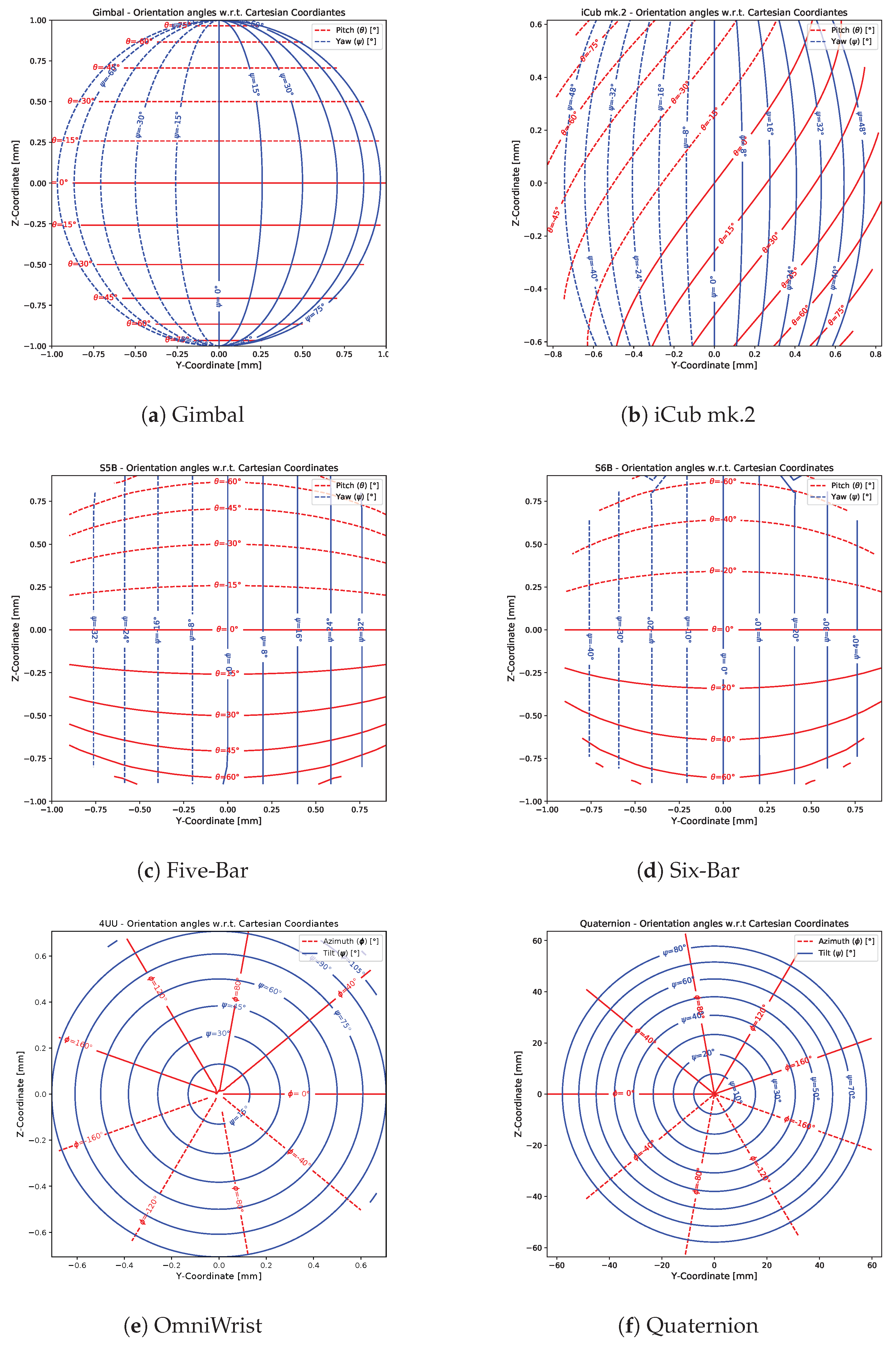
6.3. Orientation Angles with Regard to Normalized Cartesian Coordinates
The
Figure 7 show the
contour mapping of the orientation angles (pitch and yaw or the azimuth and tilt angles for the respective cases) with respect to the normalized Cartesian coordinates of point
P on the platform. These plots depict the coupling between the position and the orientation of the mobile platform. For both the spherical linkage mechanisms, only the platform yaw exhibits a linear relation with its position in the Cartesian space (
Figure 7c,d) and this behavior is symmetric. Similarly, both the Omniwrist (
Figure 7e) and the Quaternion (
Figure 7f) mechanisms, the platform tilts perfectly symmetric about the torsional axis (X-axis).
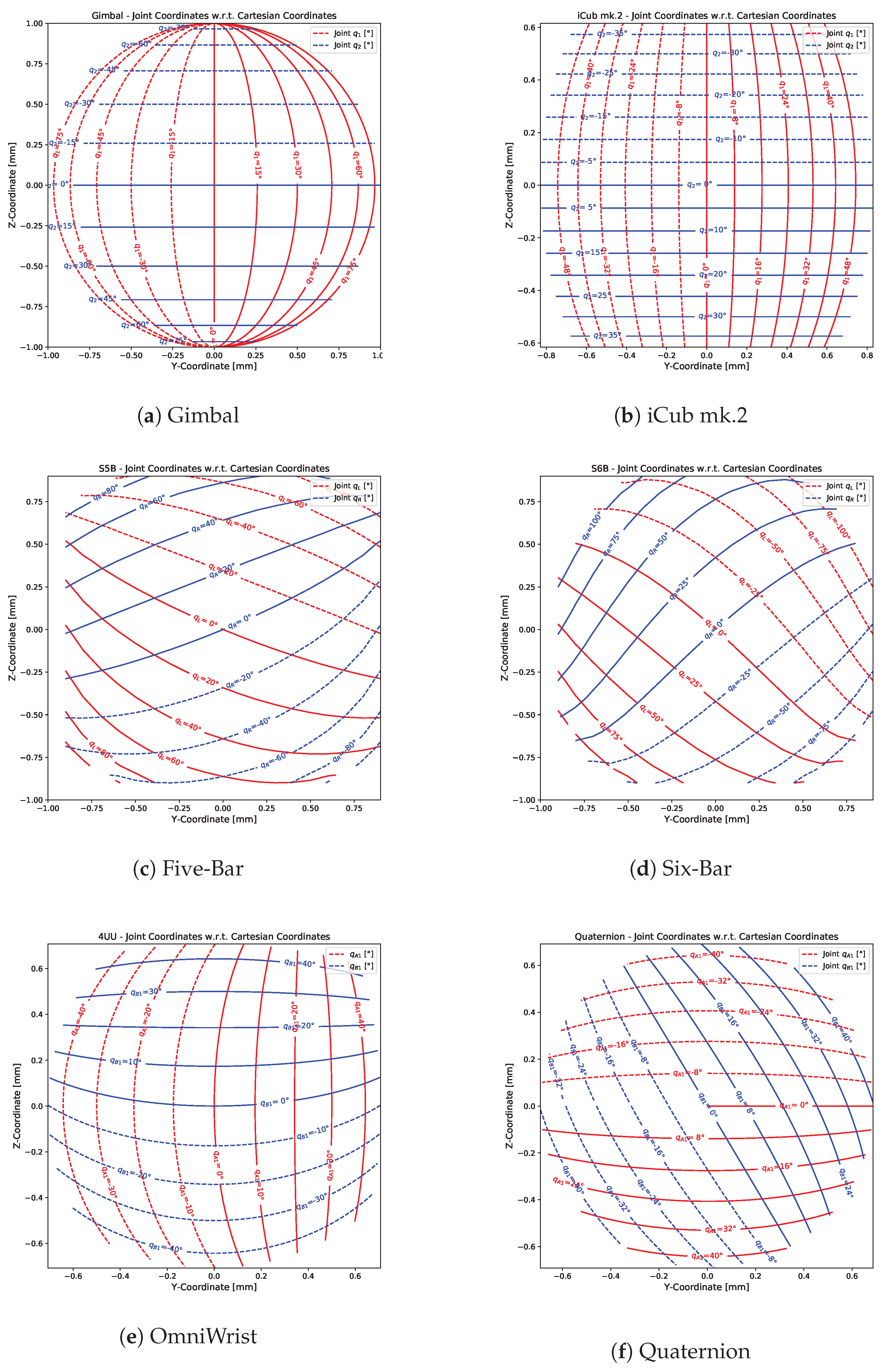
6.4. Joint Coordinates with Regard to Normalized Cartesian Coordinates
The
Figure 8 show the
contour mapping of the actuator joint coordinates with respect to the normalized platform coordinates in the Cartesian space. These plots show the coupling between the platform position and the input joint angles. The plots for the gimbal (
Figure 8a) and the iCub mk.2 wrist (
Figure 8b) show a symmetric relation, as expected. In addition, again, it is observed that the five-bar and six-bar mechanisms (
Figure 8c,d) show a quasi-linear relation albeit skewed. The Omniwrist plot (
Figure 8e) is not symmetric with respect to the zero-abscissa and zero-ordinate axes, thus further implying the “warping” behavior of the workspace. On the other hand, the Quaternion joint plot (
Figure 8f) is fairly regular.
7. Discussion
Some of the important observations from the analyses presented above are summarized in
Table 2 and are discussed as follows:
Similar to the gimbal mechanism, only the Omniwrist and the Quaternion joint mechanisms provide a full hemispherical workspace (
Figure 5). Consequently, these two exhibit the highest orientational range of motion (Tilt up to 90°). The restriction of the yaw motion for the spherical linkage mechanisms arises possibly due to the presence of kinematic singularities.
From the input to output mapping (
Figure 6), only the gimbal mechanism has a perfect decoupled DOF. All the other cases show dependence on both the inputs for 1 pure DOF, except yaw motion for iCub mk.2.
For the cases of Omniwrist and Quaternion joint mechanism, the highest amplification of inputs to the output is observed, that is, for a range of ≈° of the actuators, full tilt of 90° is achieved.
The relation between the platform position and its orientation is observed to be fairly symmetric and regular in all the cases (
Figure 7).
The relation between the input joint angles and the platform position in the case of the Omniwrist mechanism (
Figure 8) illustrates an example of asymmetric “warping” behavior of the workspace.
From the analyses thus presented, both the Omniwrist and the Quaternion joint mechanisms stand out. However, the non-linear behaviors described above for the Omniwrist case have significant consequences for the actual mechanism implementation and control. Firstly, the same control input given to the system in two different configurations will yield significantly different output motions. This issue could, in theory, be solved by using configuration-dependent actuator PID gains, but this would imply a substantial complication of the existing robot control infrastructure. For these reasons, and given the desired design objectives, the Quaternion joint mechanism seems to be most suitable for implementation for the iCub humanoid wrist. Further research efforts will be devoted towards analytical kinematics and parameter optimization of this mechanism for the subsequent development of the new iCub wrist. It shall finally be noted that a series of alternative decoupled 2DOF wrist architectures were proposed by Carricato in [
19]. Although simple CAD implementations of these architectures do not seem to comply with the aforementioned constraints, further work is needed to thoroughly evaluate the viability of this option for the iCub platform.
8. Conclusions
With the vision of developing a new dexterous wrist for the iCub humanoid, a comparative analysis of several state-of-the-art robot wrist implementations was presented. The spherical five-bar linkage, spherical six-bar linkage, OmniWrist-III mechanism, and the Quaternion joint mechanism were modeled and simulated using PTC Creo Parametric 4.0. The platform positions and orientation angles for each of these mechanisms were analyzed and compared against the standard 2DOF gimbal mechanism and the current iCub mk.2 wrist implementation. The Quaternion joint mechanism emerges as a promising candidate for the new iCub wrist and calls for further exploitation towards the design and development of the wrist, as well as for a better modeling of its kinematics.

 ,
, 
