Article

Vacuum-Actuated Bending for Grasping

Schlumberger-Doll Research, 1 Hampshire St., Cambridge, MA 02139, USA
*
Author to whom correspondence should be addressed.
Now a Senior Associate with Exponent, 9 Strathmore Road, Natick, MA 01760, USA.
Robotics 2018, 7(4), 73; https://doi.org/10.3390/robotics7040073
Submission received: 19 October 2018 / Revised: 9 November 2018 / Accepted: 13 November 2018 / Published: 16 November 2018
(This article belongs to the Special Issue Soft Machines: Integrating Sensing, Actuation and Computation)

Abstract

:
Soft robotic devices typically are actuated with the application of a positive pressure (compared to ambient pressure), but some exciting work has been done with negative pressure application, with advantages for safety and robustness. Here, we present a negative pressure bending actuator inspired by previous work by Yang et al., fabricated using rapid prototyping techniques and elastomeric polymers. We describe the mechanical behavior of the system from a cellular solids perspective, showing the steps needed for the analysis and characterization of future similar systems. We find good agreement between experimentally measured values of displacement and force generated in atmospheric pressure conditions.

Graphical Abstract

1. Introduction

Soft robotics enable devices to mimic natural constructs [1,2] and provide information-rich interactions with the environment when embedded with sensors [3,4]. Indeed, with many applications and design factors to consider, soft robotics is a fertile ground for cross-disciplinary contributions and collaborations [5,6,7]. Understanding soft robotic actuators and their behavior for modeling and control requires mechanical analysis involving large deflections and instabilities. A growing body of work studies metamaterials that consist of a material with strategically placed and shaped voids [8,9,10,11,12,13,14,15], which, when compressed, exhibit unique mechanical responses such as a negative Poisson’s ratio. These materials present an opportunity for soft robotics. Metamaterials allow for a negative pressure differential, with ambient pressure as the actuation source. This strategy has been applied in spheres that can encapsulate/release with pressure changes [16], in linear actuators [17], and in actuators with a changeable surface pattern enabling twisting or bending [18].
In this study, we present a bending actuator inspired by previous work on linear actuators [17]. Instead of coupling this linear actuator with rigid parts [19,20], which has been shown to achieve promising results, we aim to keep the actuator fully soft. A cellular solid material is produced, consisting of square and rectangular voids inspired by negative Poisson’s ratio materials [21] with the same geometry as studied in [17], but in a different elastomeric material. This cellular solid is encapsulated on all sides, and the voids are interconnected so that a pressure differential can be applied between the internal and external volumes of the structure. On one face of the actuator parallel to the cellular solid plane, a thin stiff layer is added. When the cellular solid is actuated, the whole structure bends instead of shrinking linearly. Utilizing a negative pressure differential is advantageous, as it eliminates the risk of bursting associated with the more common positive pressure actuation. The cellular structure and negative pressure actuation combine to make a repairable and robust design to small damage. Furthermore, as more industrial work occurs in the subsea environment [22], it becomes advantageous to design manipulators that can take advantage of the hydrostatic pressures at depth. Previous work with soft robotics tested to depths of 800 m [23] have relied on a positive pressure actuation, which also requires the careful design of systems to avoid a chemical release in the case of a burst actuator.
The remainder of this paper proceeds as follows: The design and construction of the actuator is described in Section 2, and the kinematics of the actuator are described in Section 3, where we first outline the mechanical behavior of cellular solids alone and then in conjunction with a stiff layer. The experimental setup is described in Section 4, and results are presented for characterization of the cellular solid as well as displacement and force generation of the actuator system.

2. Actuator Structure and Construction

As described above, our actuator was constructed as a bilayer beam with a thin stiff layer bonded to a thicker, more compliant layer. The thick layer was a cellular solid (meta-material) composed of solid and interconnected void spaces. The thick layer was isolated from the ambient atmosphere by an encapsulating skin, allowing for controlling the differential pressure. For ease of mold design as well as comparison to previous results, we chose to use a patterned void space as in [19]. The macro-dimensions of the overall bi-layer beam were 93 mm long (L) × 34.0 mm wide (b) × 31 mm thick (h), composed of a 29 mm-thick cellular solid layer, and two 1.5 mm-thick soft outer encapsulating faces). The stiff layer was bonded to one of the soft faces and was 0.37 mm thick. For the microstructure, voids could either be “large” (11 mm wide, w c 2 in Figure 1c, by 6 mm long, h c ) or “small” (6 mm wide, w c 1 by 6 mm long). Voids were separated horizontally by “thick” columns (4 mm, t v in Figure 1c) and vertically by “thin” beams (1.5 mm, t h ). The skin of the sides and faces of the beam were 1.5 mm thick. For materials, the thin stiff layer was made out of card stock with a Young’s modulus, E, of 2–4 GPa [24]. We assumed E = 2 GPa for subsequent analysis, although the effect on model predictions of varying E over the range of 2–10 GPa was found to be negligible. The solid component of the meta-material was made out of a silicone-based elastomer (Zhermack Elite Double 8, a two part vinylpolysiloxane polymer) with E = 220 kPa [11].
A two-part mold was fabricated using stereolithography 3D printing with Accura 60 (similar to polycarbonate), as shown in Figure 1a,b. Each mold accounted for one quarter of the overall beam structure. To fabricate the beam, four smaller sections were molded with the Zhermack Elite Double 8 elastomer, one of which is shown in Figure 1c. Each of the four units was length L / 2 , width b, and thickness h / 2 . Two long parts were made by fusing two molded units end to end (making a unit of length L, width b, and thickness h / 2 ). Each of these long parts was joined along the outside edge of the face open to the cellular solid (such that the cellular solid structure was encapsulated), resulting in an actuation with length L, width b, and thickness h. The interface between the cellular solid faces was not fused, allowing free airflow between the voids. A single piece of card stock approximately 90 mm long × 32 mm wide × 0.37 mm thick was placed on a face of the structure, parallel to the plane of the microstructure, as shown in Figure 1d. Fresh polymer was placed under and over the card stock as well as along its edges to bond it with the beam structure, as shown in Figure 1e. An air hose connection was placed at one end of the beam, connected to the void space, and fused onto the overall structure, allowing for pneumatic control of the actuator. The cross section of the actuator is shown in Figure 1f.
For creating the sample used to characterize the cellular solid, only two monolithic parts were fabricated entirely with Zhermack Elite Double 8 and fused together to create a structure half as long as the beam used for the actuator. This length was sufficient to test the properties of the cellular solid under pressure differential, as discussed in the next section.

3. Actuator Kinematics

3.1. Mechanical Behavior of Cellular Solids

We analyzed the mechanical behavior of our actuator with a cellular solids framework [24], allowing us to provide a generalized approach for actuator design and to provide a different viewpoint of the problem from [17], which took a more thermodynamics-based approach. An important parameter for cellular solids analysis is the relative density, ρ / ρ s , which is the ratio of the volumetric mass density of the overall cellular solid, ρ , to the density of the constituent solid material, ρ s . We follow the convention throughout the remainder of the paper that parameters with an asterisk (*) indicate properties of the cellular solid and the absence of an asterisk indicates fully dense material (sometimes further indicated with an “s” subscript). For a cellular solid composed of a single material, this is equivalent to the volume fraction of the solid. While often a measured value for natural and manufactured foams, the selected geometry for our system is simple enough to compute the relative density as
ρ ρ s = ( 2 t h + 2 h c ) ( 3 t w + 2 w c 2 ) ( 3 h c w c 2 + 2 h c w c 1 ) ( 2 t h + 2 h c ) ( 3 t w + 2 w c 2 ) ,
where t h is the thickness of the horizontal beam elements, h c is the height of the voids, t w is the width of the thick vertical columns, w c 1 is the width of the smaller voids, and w c 2 is the width of the larger voids, as shown in Figure 1c.
A common feature of both natural and fabricated cellular solids is orthotropic material properties (having three mutually orthogonal directions with differing material properties) [24]. As can be seen in Figure 1c, the structure considered follows this trend, wherein we expect the structure to be most compliant in the 1 direction due to bending the thin horizontal beams and least compliant in the 3 (out of plane) direction due to compressing solid material without bending. This can be alternatively expressed as E 1 < E 2 E 3 , where again subscript numbers indicate direction (as defined in Figure 1c) and asterisk indicates a cellular solid property.
The value of ρ / ρ s is useful for calculating [24] the Young’s modulus, E i , of dense (relative density over 30%):
E i = C 1 i E s ρ ρ s 2 1 1 + ρ / ρ s ,
where C 1 i is a coefficient that must be determined from experiments for each direction i. As deformations out of the plane of the cellular solid (direction 3 in Figure 1c) are dictated by the solid material stiffness whereas the in-plane deformations (directions 1 and 2 in Figure 1c) are dominated by bending, a plane strain assumption is made, allowing a reduction in the calculation of deformations in the linear-elastic regime along the two principal in-plane directions. Furthermore, we are primarily interested in deformations in the 2 direction (axial direction of our actuator) [24]:
ϵ 2 = 1 E 2 σ 2 ν 21 σ 1 ν 23 σ 3 ,
where ϵ 2 indicates strain in the 2 direction and ν 2 i = ϵ i / ϵ 2 is the Poisson’s ratio in the i direction due to loading in the 2 direction, where i = 2 , 3 .
The actuator system will experience uniform non-deviatoric stress loading such that σ 1 = σ 2 = σ 3 . Furthermore, this stress will be the difference in pressure between atmospheric pressure, P a t m , and the pressure inside the voids of the cellular solid, P i n . This pressure differential, Δ P will be defined to be positive as the pressure inside the matrix of the cellular solid drops below atmospheric: Δ P = P a t m P i n . Lastly, an equivalent expression for ν 23 = ( E 2 / E 3 ) ν s , where ν s is the bulk material Poisson ratio and E i is the Young’s modulus is the i direction. The planar cellular solid is much stiffer in the out-of-plane direction (3 direction) than either in-plane direction, making ν 23 0 . Using this knowledge, we can simplify Equation (3) for the linear-elastic strain along the long axis of the actuator system, ϵ 2 ,
ϵ 2 = 1 E 2 1 ν 21 Δ P .
With Equation (4), we have a direct relationship between the axial strain and applied pressure for our cellular solid system. This can be thought of in similar terms of a coefficient of thermal expansion or swelling parameter. To avoid confusion in subsequent mechanical analysis and to conform with standard literature notation, we shall refer to this strain as α , with the negative sign indicating that a positive value of α corresponds to a compressional (negative) strain in the 2 direction. Substituting Equation (2) into Equation (4), we obtain
ϵ 2 ( Δ P ) = α = 1 C 12 ( 1 ν 21 ) Δ P E s 1 + ρ ρ s ρ ρ s 2 ,
which expresses axial strain as a function of known parameters, E s and ρ / ρ s , a control parameter, Δ P , a measurable quantity, ν 21 , and a single fitting parameter, C 12 .
We expect the linear-elastic assumptions to be valid up to an elastic collapse stress, σ e l , where [24]
σ e l 0.03 ρ ρ s 2 1 + ρ ρ s 1 / 2 2 ,
after which a short plateau region of increasing strain under approximately constant stress will precede a rapid strain hardening regime as cell walls deform enough to contact and the structure’s stiffness approaches that of the constituent solid (known as densification [24]).

3.2. Composite Bending

Considering the bonding of our cellular solid matrix with a thin stiff membrane, we arrive at the classical mechanics problem of a bilayer, whereby differential expansion/contraction of the two layers results in bending of the overall structure [25], as bending is energetically favorable to stretching. Further examination of the problem reveals a tri-layer problem, with the first layer being the thin, stiff card stock layer bonded to a softer Elite Double 8 layer with a cellular solid structure which is bonded to a third Elite Double 8 layer with a cellular solid structure (referred to as layers 1, 2, and 3, as shown in Figure 2). The difference between layers 2 and three is actuation: layer 2 will not actuate ( α = 0 ) with a pressure differential, whereas layer 3 will ( α 0 ).
Our cellular solids analysis assumed that the constraints imposed by the encapsulating layer surrounding the cellular solid were negligible and that the faces would essentially deform as needed to allow the microstructure’s members to bend as needed. However, layer 2 being bonded to a much stiffer layer 1 restricts that motion considerably. The 1 mm air gap between layers 2 and 3 is likely reduced to a negligible gap upon initial pressurization, leaving 28 mm of cellular solid material (with there being another 1.5 mm of Elite Double 8 polymer as the face opposite the card stock). Finding the boundary between layers 2 and 3 is discussed in the Results Section.
Bilayer and tri-layer actuation systems were modeled for the case of conjugated polymer actuators (a gold conducting layer over an electroactive polymer which can produce curvature from swelling/shrinkage in the presence of electrical current) in [26,27]. For the case of constant modulus and actuation strain, α , for each layer, the closed form solution for beam curvature was found to be [27]:
κ = α h 1 6 m a n a 1 + m a + m a 2 n b + m b ( 2 + m a n b ) 1 + m b 4 n b 2 + 4 m a n a + 6 m a 2 n a + 4 m a 3 n a + 4 m b 3 ( n b + n a n b n a ) + 6 m b 2 ( ( n b + 2 m a n a + m a 2 n b n a ) + 4 m b ( n b + 3 m a ( 1 + m a ) n a + m 3 n b n a ,
where m a = t 3 / t 1 , m b = t 2 / t 1 , n a = E 3 / E 1 , and n b = E 2 / E 1 . This case simplifies to the classic bilayer solution [25] when m b 0 and α is taken to the be coefficient of thermal expansion. With Equations (5) and (7), we can now express actuator curvature as a function of applied differential pressure, which will allow for a direct comparison to experimental results.
The moment generated per unit width, M, to create the beam curvature in Equation (7) can be expressed, in the case of a tri-layer beam, as [27]:
M = E 1 h 1 2 m a n a ( 1 + m a + m b 2 n b + m b n a ( 2 + m a n b ) ) 2 ( 1 + m b n b + m a n a ) α ,
which would result in a reaction force (in the case of a beam blocked by a point load at the tip) of [27]:
F = 3 b M 2 L ,
where b is the beam width and L is the beam length.

4. Results

4.1. Setup

The actuator was mounted on an acrylic plate which had a hole large enough for the pneumatic connection to pass through. A water-filled U-tube of flexible PVC tubing was hung under the acrylic plate with a 50 mL syringe connected to the air volume of the actuator. The other end of the U-tube was left open to atmospheric pressure. The whole setup is shown schematically in Figure 3a. For experiments, a Nikon D5200 digital SLR camera was mounted on a tripod viewing the specimen in profile to record the horizontal displacement of the free tip. The syringe was manually controlled to produce a change in the water head, δ h , of 25.4 ± 1.6 mm (equal to a change in Δ P of 250 ± 15 Pa) before the next photo was taken. For actuator test series, images were analyzed by tracking the horizontal displacement, δ , of the upper-left corner of the beam as it deflected, as shown in Figure 3b,c.
Two other tests were run with the same pneumatic connections: one for characterizing the cellular solid response to pressure differential (measuring C 12 to give α from Equation (5)) and another test to measure the force generated from a blocked actuator. The initial conditions of these tests are shown in Figure 3d,e, respectively.

4.2. Cellular Solid Characterization
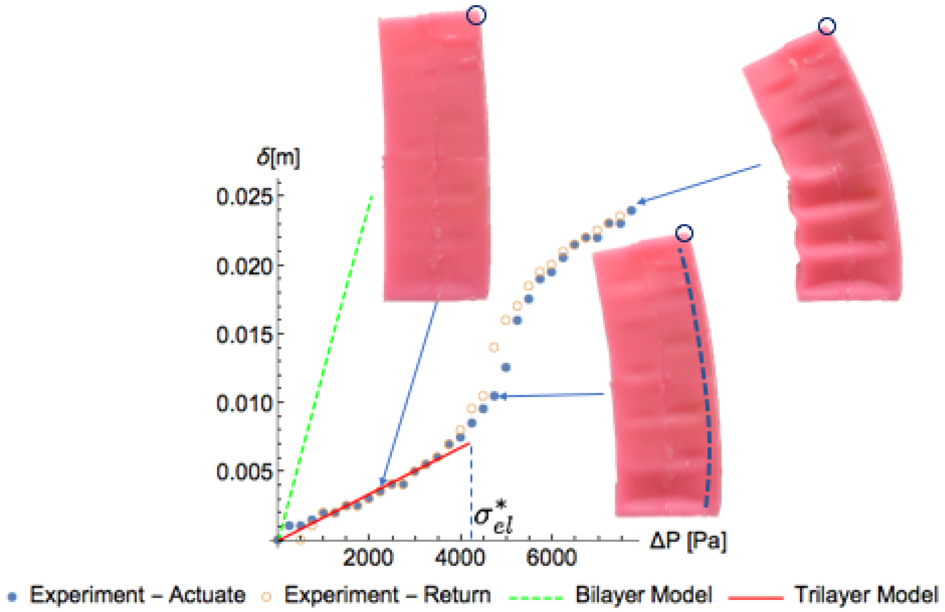
The mechanical analysis of our actuator system began with the characterization of the actuating meta-material. The relative density, ρ / ρ s , of our cellular solid was calculated directly using Equation (1) as 0.471. Using this value along with the Young’s modulus of the solid material, E s = 220 kPa, we calculated the elastic collapse stress, σ e l , below which we expect approximately linear stress–strain behavior, to be 4155 Pa. We used a 1-D Deltron ball slide positioning stage and Canon EOS 70D digital SLR camera to measure the Poisson ratio of the microstructure (images processed with Fiji software [28]) to be ν 21 = 0.33 over 10% compressive strain in the 2-direction (we acknowledge that a constant ν is a simplification for this type of cellular solid, which will exhibit auxetic behavior above a critical strain—e.g., see [9]). Figure 4 shows a plot of experimentally measured values of actuation strain (defined as an engineering strain), α = Δ l / l 0 , as a function of applied differential pressure, Δ P . Photographs of three representative sample configurations during actuation are shown, with the point tracked for strain calculations (originally 27.1 mm from the base of the sample) indicated with a green circle. Solid points in the plot indicate values during actuation, and hollow circles indicate points measured while returning the actuator to its original configuration (decreasing Δ P back to 0). As can be seen in Figure 4, there is very little hysteresis during actuation and return, and we see three distinct regions of mechanical behavior. Below the predicted value of σ e l 4.1 kPa, we see approximately linear behavior. At stresses higher than σ e l , we see a brief plateau with increasing strain at constant pressure of approximately 5 kPa followed by a stiffening behavior. This stiffening region is the onset of densification, were we see opposite cells walls nearly touching in the last representative photograph.
Using the experimental points during actuation up to the predicted elastic collapse stress, we used a linear fit of the data to calculate our observed value of C 12 from Equation (5) to be 0.3356. Out-of-plane deformations are clearly observable in the upper half of the sample in the last two representative photographs. This behavior was not predicted in our linear cellular solids analysis, which reinforces the limitation of analysis to the initial linear regime of behavior. While a single actuation cycle is presented, we observed the actuation to be repeatable across several cycles. However, no reliability study was performed.

4.3. Displacement

Figure 5 plots the lateral displacement of the tip of the stiff layer, δ , as a function of the applied pressure differential, Δ P . A negligible amount of hysteresis was observed. The tip displacement behavior matched that of the cellular solid strain, with an initial linear portion, followed by a short plateau region, finishing with a densification zone. Two model predictions are plotted with the experimental data: the bilayer model with a dashed green line (which assumes all of the cellular solid material actuates under differential pressure) and the tri-layer model with a solid red line (which assumes a region of non-actuating cellular solid material between the stiff layer and actuating cellular solid material). The bilayer model clearly over-predicted the displacement of the actuator prior to elastic collapse of the actuator, whereas the tri-layer model was in good agreement with measured values. For both models, the curvature calculated in Equation (7) was converted to a tip displacement through the relation δ = 1 κ ( α ) ( 1 cos ( κ ( α ) L ) ) , where L is the length of the beam. Again, while a single actuation cycle is presented, we observed tip displacement to be repeatable across several cycles, but no in-depth reliability study was performed.
Choosing the thickness of the middle layer of the tri-layer model was accomplished by measuring the zone on the material close to the stiff layer that did not appear to actuate when viewing the sample in profile. In Figure 5, one can observe the thin sidewalls distorting into the cellular voids. However, there was a zone, measured to be approximately constant across pressures as 5.5 mm thick, which did not appear to be pulled into the voids. This boundary is indicated in Figure 5 on the middle representative photograph as a dashed line, but did appear nearly immediately upon initial depressurization. To plot the tri-layer model shown, the curvature of the actuator was calculated according to Equation (7), using t 1 = 0.37 mm, t 2 = 5.5 mm, and t 3 = 22.5 mm. The Young’s moduli used were E 1 = 2 GPa (varying E 1 in the range of 2–4 GPa had negligible effect) and E 2 = E 3 = E = 10,923 Pa (calculated from Equation (2)).

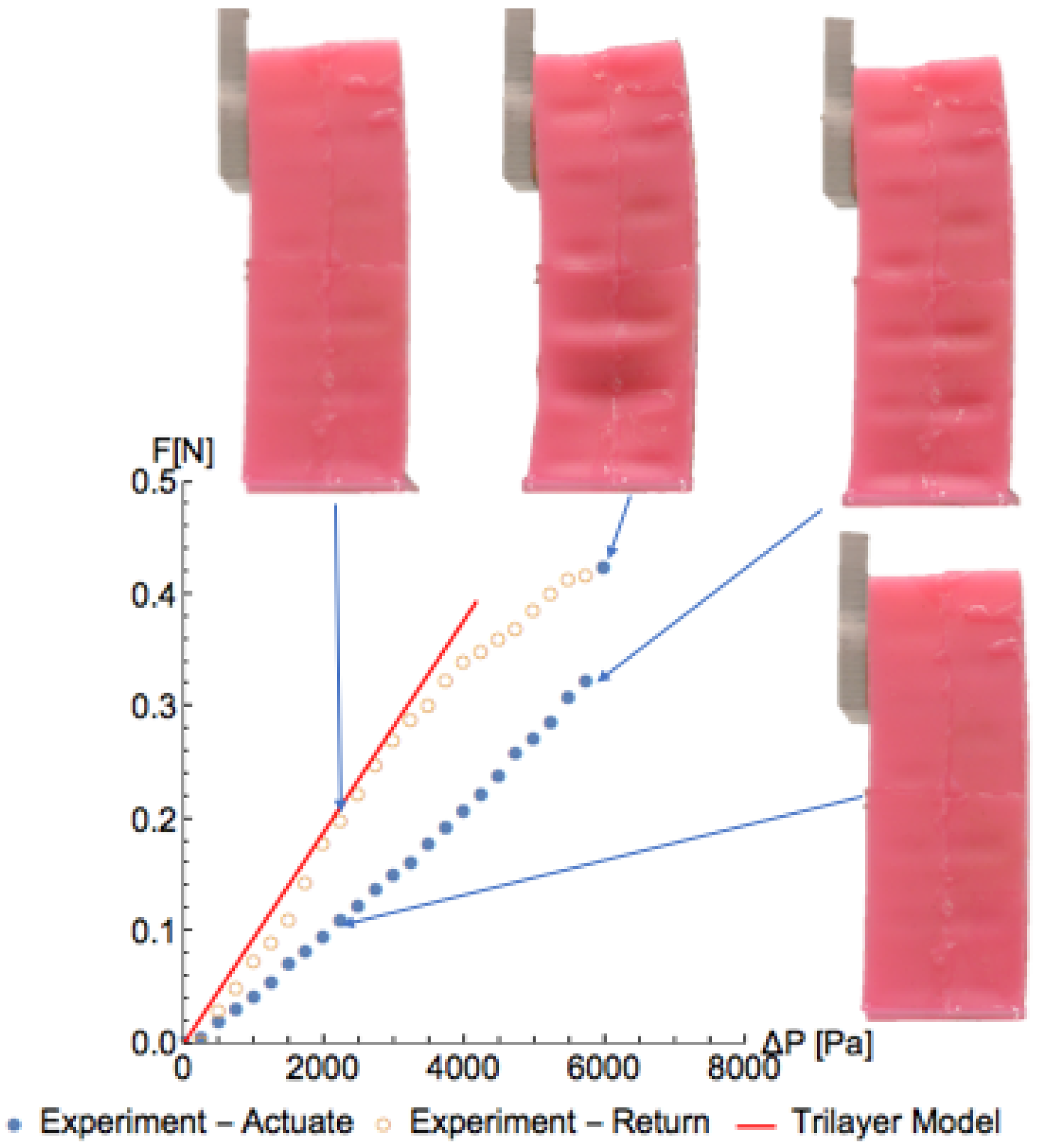
4.4. Force Generation

The force generated during actuation was also experimentally measured by blocking the free end of the actuator with a 2.5 cm acrylic square mounted to a Futek miniature S-beam load cell in line with the direction of force application, as shown in Figure 6. Solid points indicate points measured during actuation, and hollow points are those recorded during return of the actuator. Four photographs of the actuator during the experiment are also shown for the indicated points. There was a highly linear response of actuation force, F, to differential pressure up to a critical value between Δ P = 5.73 and 5.98 kPa, when the structure buckled slightly (with a noticeable change in the actuator observed near the bottom end). As the actuator returned to Δ P = 0 kPa, we again saw a linear relationship between F and Δ P .
The red solid line in Figure 6 is the prediction of the tri-layer model in Equation (9), and captures the return phase after actuation very well. In this configuration, the actuator was in a slightly buckled configuration. While we did not rationalize the lower actuation phase force, we hypothesize that there may be more force being exerted parallel to the long axis of the actuator on the blocking plate.

5. Conclusions and Future Work

We presented a new, negative-pressure-activated bending actuator based on linear actuator work presented in [17]. We described the system behavior using techniques from the mechanical analysis of cellular solids with good agreement with experimental results, which encourages their use for the future design and control of actuators based on similar principles. Further areas of investigation could include further mechanical analysis to rationalize the thickness of the non-actuating layer of cellular solids as well as practical studies into the cyclical fatigue life of this style of actuator as well as developing control schemes for force and speed control. Embedding sensors into soft robotics, especially for haptic feedback, is an exciting area of research in which this style of actuator could be augmented to participate.
References

Author Contributions

Conceptualization, J.T.M. and N.W.; Investigation, J.T.M.; Writing—Original Draft Preparation, J.T.M.; Writing—Review & Editing, N.W. and J.T.M.

Funding

This research received no external funding.

Acknowledgments

The authors wish to thank Jahir Pabon and Tianxiang Su for helpful conversations and Schlumberger for supporting publication of this work.

Conflicts of Interest

The authors declare no conflict of interest.

References

  1. Marchese, A.D.; Onal, C.D.; Rus, D. Autonomous soft robotic fish capable of escape maneuvers using fluidic elastomer actuators. Soft Robot. 2014, 1, 75–87. [Google Scholar] [CrossRef] [PubMed]
  2. Shepherd, R.F.; Ilievski, F.; Choi, W.; Morin, S.A.; Stokes, A.A.; Mazzeo, A.D.; Chen, X.; Wang, M.; Whitesides, G.M. Multigait soft robot. Proc. Natl. Acad. Sci. USA 2011, 108, 20400–20403. [Google Scholar] [CrossRef] [PubMed] [Green Version]
  3. Morrow, J.; Shin, H.S.; Phillips-Grafflin, C.; Jang, S.H.; Torrey, J.; Larkins, R.; Dang, S.; Park, Y.L.; Berenson, D. Improving Soft Pneumatic Actuator fingers through integration of soft sensors, position and force control, and rigid fingernails. In Proceedings of the 2016 IEEE International Conference on Robotics and Automation (ICRA), Stockholm, Sweden, 16–21 May 2016; pp. 5024–5031. [Google Scholar]
  4. Homberg, B.S.; Katzschmann, R.K.; Dogar, M.R.; Rus, D. Haptic identification of objects using a modular soft robotic gripper. In Proceedings of the 2015 IEEE/RSJ International Conference on Intelligent Robots and Systems (IROS), Hamburg, Germany, 28 September–2 October 2015; pp. 1698–1705. [Google Scholar]
  5. Ilievski, F.; Mazzeo, A.D.; Shepherd, R.F.; Chen, X.; Whitesides, G.M. Soft robotics for chemists. Angew. Chem. 2011, 123, 1930–1935. [Google Scholar] [CrossRef] [Green Version]
  6. Lu, N.; Kim, D.H. Flexible and stretchable electronics paving the way for soft robotics. Soft Robot. 2014, 1, 53–62. [Google Scholar] [CrossRef]
  7. Cianchetti, M.; Ranzani, T.; Gerboni, G.; Nanayakkara, T.; Althoefer, K.; Dasgupta, P.; Menciassi, A. Soft robotics technologies to address shortcomings in today’s minimally invasive surgery: The STIFF-FLOP approach. Soft Robot. 2014, 1, 122–131. [Google Scholar] [CrossRef]
  8. Bertoldi, K.; Boyce, M.C.; Deschanel, S.; Prange, S.; Mullin, T. Mechanics of deformation-triggered pattern transformations and superelastic behavior in periodic elastomeric structures. J. Mech. Phys. Solids 2008, 56, 2642–2668. [Google Scholar] [CrossRef]
  9. Bertoldi, K.; Reis, P.M.; Willshaw, S.; Mullin, T. Negative Poisson’s ratio behavior induced by an elastic instability. Adv. Mater. 2010, 22, 361–366. [Google Scholar] [CrossRef] [PubMed] [Green Version]
  10. Bertoldi, K.; Vitelli, V.; Christensen, J.; van Hecke, M. Flexible mechanical metamaterials. Nat. Rev. Mater. 2017, 2, 17066. [Google Scholar] [CrossRef] [Green Version]
  11. Florijn, B.; Coulais, C.; van Hecke, M. Programmable mechanical metamaterials. Phys. Rev. Lett. 2014, 113, 175503. [Google Scholar] [CrossRef] [PubMed]
  12. Mullin, T.; Deschanel, S.; Bertoldi, K.; Boyce, M.C. Pattern transformation triggered by deformation. Phys. Rev. Lett. 2007, 99, 084301. [Google Scholar] [CrossRef] [PubMed]
  13. Overvelde, J.T.; Shan, S.; Bertoldi, K. Compaction through buckling in 2D periodic, soft and porous structures: Effect of pore shape. Adv. Mater. 2012, 24, 2337–2342. [Google Scholar] [CrossRef] [PubMed] [Green Version]
  14. Overvelde, J.T.; Bertoldi, K. Relating pore shape to the non-linear response of periodic elastomeric structures. J. Mech. Phys. Solids 2014, 64, 351–366. [Google Scholar] [CrossRef]
  15. Taylor, M.; Francesconi, L.; Gerendás, M.; Shanian, A.; Carson, C.; Bertoldi, K. Low porosity metallic periodic structures with negative Poisson’s ratio. Adv. Mater. 2014, 26, 2365–2370. [Google Scholar] [CrossRef] [PubMed] [Green Version]
  16. Shim, J.; Perdigou, C.; Chen, E.R.; Bertoldi, K.; Reis, P.M. Buckling-induced encapsulation of structured elastic shells under pressure. Proc. Natl. Acad. Sci. USA 2012, 109, 5978–5983. [Google Scholar] [CrossRef] [PubMed] [Green Version]
  17. Yang, D.; Verma, M.; So, J.H.; Mosadegh, B.; Keplinger, C.; Lee, B.; Khashai, F.; Lossner, E.; Suo, Z.; Whitesides, G.M. Buckling Pneumatic Linear Actuators Inspired by Muscle. Adv. Mater. Technol. 2016, 1. [Google Scholar] [CrossRef]
  18. Lazarus, A.; Reis, P.M. Soft actuation of structured cylinders through auxetic behavior. Adv. Eng. Mater. 2015, 17, 815–820. [Google Scholar] [CrossRef]
  19. Yang, D.; Mosadegh, B.; Ainla, A.; Lee, B.; Khashai, F.; Suo, Z.; Bertoldi, K.; Whitesides, G.M. Buckling of elastomeric beams enables actuation of soft machines. Adv. Mater. 2015, 27, 6323–6327. [Google Scholar] [CrossRef] [PubMed]
  20. Yang, D.; Verma, M.S.; Lossner, E.; Stothers, D.; Whitesides, G.M. Negative-Pressure Soft Linear Actuator with a Mechanical Advantage. Adv. Mater. Technol. 2017, 2, 1600164. [Google Scholar] [CrossRef]
  21. Bowick, M.; Cacciuto, A.; Thorleifsson, G.; Travesset, A. Universal negative Poisson ratio of self-avoiding fixed-connectivity membranes. Phys. Rev. Lett. 2001, 87, 148103. [Google Scholar] [CrossRef] [PubMed]
  22. Shukla, A.; Karki, H. Application of robotics in offshore oil and gas industry—A review Part II. Robot. Auton. Syst. 2016, 75, 508–524. [Google Scholar] [CrossRef]
  23. Galloway, K.C.; Becker, K.P.; Phillips, B.; Kirby, J.; Licht, S.; Tchernov, D.; Wood, R.J.; Gruber, D.F. Soft robotic grippers for biological sampling on deep reefs. Soft Robot. 2016, 3, 23–33. [Google Scholar] [CrossRef] [PubMed]
  24. Gibson, L.J.; Ashby, M.F. Cellular Solids: Structure and Property; Cambridge University Press: Cambridge, UK, 1999. [Google Scholar]
  25. Timoshenko, S. Analysis of bi-metal thermostats. JOSA 1925, 11, 233–255. [Google Scholar] [CrossRef]
  26. Christophersen, M.; Shapiro, B.; Smela, E. Characterization and modeling of PPy bilayer microactuators: Part 1. Curvature. Sens. Actuators B Chem. 2006, 115, 596–609. [Google Scholar] [CrossRef]
  27. Shapiro, B.; Smela, E. Bending actuators with maximum curvature and force and zero interfacial stress. J. Intell. Mater. Syst. Struct. 2007, 18, 181–186. [Google Scholar] [CrossRef]
  28. Schindelin, J.; Arganda-Carreras, I.; Frise, E.; Kaynig, V.; Longair, M.; Pietzsch, T.; Preibisch, S.; Rueden, C.; Saalfeld, S.; Schmid, B.; et al. Fiji: An open-source platform for biological-image analysis. Nat. Methods 2012, 9, 676–682. [Google Scholar] [CrossRef] [PubMed]
Figure 1. (a) Negative mold used for creating the actuator. (b) Two-part silicone-based polymer poured into mold. (c) Monolithic structure composed of Zhermack Elite Double 8 with voids with widths of w c 1 = 6 or w c 2 = 11 mm, height h c = 6 mm, vertical columns t v = 4 mm wide, and horizontal beams t h = 1 . 5 mm thick (flashing is still visible around the edges from demolding). Directions 1 and 2 are defined to be in the plane of the cellular structure. (d) Four molded parts are joined to create a beam with a stiff card stock placed on one side parallel to the plane of the cellular structure. (e) The card stock is fused to the beam structure with more Elite Double 8. Overall beam dimensions are 93 mm long (L) × 34 mm wide (b) × 31 mm thick (h). (f) Cross section of the actuator.
Robotics 07 00073 g001
Figure 2. Tri-layer structure of the actuator system. Layer 1 is a thin stiff layer with thickness t 1 and Young’s modulus E 1 . Layers 2 and 3 have a cellular solid microstructure with E 2 = E 3 = E . Layer 3 is the actuation layer, and exhibits a strain dependent on external pressure, α = α ( Δ P ) .
Robotics 07 00073 g002
Figure 3. (a) Schematic of the experimental setup, involving a sample mounted on a horizontal acrylic plate. A U-tube is connected to the bottom of the sample, with a syringe used to control the volume of air in the left of the U-tube and sample. The pressure differential, Δ P = P a t m P i n , between atmospheric pressure and the internal pressure is measured by the height differential of the water levels in the U-tube, δ h . (b) Un-actuated sample ( Δ P = 0 ). (c) Fully-actuated sample ( Δ P = 7.91 kPa) with a horizontal displacement of approximately 20 mm (vertical dashed line indicates the reference point for displacement measurements). (d) A load cell was set up to block the motion of the actuator and measure the resultant force production. (e) A half-length sample was made with no stiff layer to measure the strain due to depressurization of the cellular solid (tracking the change in the indicated length l 0 ).
Robotics 07 00073 g003
Figure 4. Actuation strain, α , as a function of applied pressure, Δ P , for the cellular solid metamaterial actuator, as well as a linear fit shown up to the predicted elastic collapse stress, σ e l .
Robotics 07 00073 g004
Figure 5. Horizontal displacement of the stiff layer tip, δ , as a function of applied pressure, Δ P , for the actuator system during actuation (solid blue points) and return (hollow orange points), as well as three representative photographs of the actuator configuration during testing at the indicated points. The dashed green line is the model prediction assuming full actuation of the cellular solid layer (the so-called bilayer model) and the solid red line is the model prediction assuming no actuation of the cellular solid within 5.5 mm of the stiff layer (the so-called tri-layer model). This matches the observed boundary between clear actuation and no observed actuation in the profile view, as indicated by the dashed line in the middle representative photograph.
Robotics 07 00073 g005
Figure 6. Horizontal reaction force, F, of the actuator as a function of applied pressure, Δ P , for a blocked test during actuation (solid blue points) and return (hollow orange points), as well as four representative photographs of the actuator configuration during testing at the indicated points. The solid red line is a prediction of the tri-layer model.
Robotics 07 00073 g006

