Abstract
This article presents a novel design of a continuum arm, which has the ability to extend and bend efficiently. Numerous designs and experiments have been done to different dimensions on both types of McKibben pneumatic muscle actuators (PMA) in order to study their performances. The contraction and extension behaviour have been illustrated with single contractor actuators and single extensor actuators, respectively. The tensile force for the contractor actuator and the compressive force for the extensor PMA are thoroughly explained and compared. Furthermore, the bending behaviour has been explained for a single extensor PMA, multi extensor actuators and multi contractor actuators. A two-section continuum arm has been implemented from both types of actuators to achieve multiple operations. Then, a novel construction is proposed to achieve efficient bending behaviour of a single contraction PMA. This novel design of a bending-actuator has been used to modify the presented continuum arm. Two different position control strategies are presented, arising from the results of the modified soft robot arm experiment. A cascaded position control is applied to control the position of the end effector of the soft arm at no load by efficiently controlling the pressure of all the actuators in the continuum arm. A new algorithm is then proposed by distributing the x, y and z-axis to the actuators and applying an effective closed-loop position control to the proposed arm at different load conditions.
1. Introduction
Recent years have seen a clear interest in designing, modelling and implementing (biological-based) continuum robot arms [1,2,3,4]. These types of robots are backbone-less structures, similar to such biological counterparts as elephant trunks and octopus arms, which have the ability of moving and bending without the need for any rigid joints. In this article, the McKibben pneumatic muscle actuator (PMA) has been used to implement this type of soft robot. This actuator has advantages when compared with typical pneumatic cylinders, such as: The high force-to-weight ratio, the need for only a small workspace, flexibility in implementing [5,6,7,8,9,10], the large number of degrees of freedom (DOF) [11,12,13], no mechanical wear, low compressed-air consumption, availability of dimension, low cost, robust reliability for human use and safe for use by human beings [7,10]. As well as these advantages, PMA has been regarded as an appropriate substitute for wide-use actuators, such as hydraulic and electrical [6,14]. Moreover, the soft robot is likely to be safer for human-robot interactions and more flexible [7,9,15].
Despite its important advantages, the PMA presents highly nonlinear performances [9,10,14,16,17,18,19] which are time dependent. The showing of nonlinearity in the PMA is caused by the compressibility of air, the inner tube elastic-viscous properties and geometrically complex performances of the braided sleeve [5,7,9]. Furthermore, the hysteresis behaviour is produced by the inner tube, which creates different characteristics of PMA during contraction and expansion [1,8,10]. These features increase the complexity of the model and control systems [5,6,7,20,21]. Also, the poorness in the rigidity makes the PMA not suitable for applications that require high force [22].
A new generation of robots have been proposed during recent decades, using this type of soft actuator. Continuum robots, with distinctive capabilities, reach places that are typically unreachable for rigid machines and risky for individuals. The low cost of the material used to build the soft robot arm makes the losses in case of an accident negligible. The continuum arms are also recognised for their varied range of grasping capabilities. They can definitely grasp objects of different forms and dimensions, as shown in [23]. The grasping can also be achieved by numerous naturally inspired approaches; for example, the continuum robot featured in [23] can grasp a plastic box like an octopus by using the suction cup.
Several soft robot arms are proposed to reach a single requirement, for example, the OctArm by [4], which is elastic, flexible and has good power, but is difficult to construct and control because of the multiple pressurised central actuators which increase the mechanical challenges for the design. McMahan, et al. [3] presented the Air-Octor continuum arm with less complexity in terms of implement and control due to the single central soft actuator and the use of tendons as actuators. However, it lacks flexibility and force because of the friction of the cable. It is difficult to overcome the friction effect caused by low pressure in the central member, which leads to cable binding and, consequently, unwanted actions of the soft arm.
Another configuration is constructed by Neppalli and Jones [24] by utilising only one extensor muscle and three tendons to position the path of the distal end. This form offers a constant arc of curvature at easiest way to control by motors, at a maximum air pressure of 483 kPa. Nevertheless, the data about the load conditions and the grasping performance is not provided by the authors.
Giannaccini, et al. [25] designed a variable stiffness continuum arm by using two layers of three contraction actuators and single extensor core actuator. Activate any of the two contraction PMAs bend the arm in one direction while the extensor actuator controls the arm stiffness.
Despite the number of prototypes and the constructed commercial continuum robots [26], numerous difficulties continue to surface in the design and kinematics of continuum robots. First, the development of a robust soft robot arm that is easy to implement and control [24]. Secondly, one that performs multiple actions, making it suitable for several applications. Moreover, the presented soft arms are constructed by using either contractor or extensor actuators.
The basic behaviour of the McKibben actuator is either contraction or expansion, depending on the structure [4,27,28]. Recently, several modifications were presented to modify the behaviour of the contractor PMA. Amongst the research, Razif, et al. [29] presented and analysed [30] a modified approach bending behaviour by using double chambers. Natarajan, et al. [31] designed a soft finger that can bend in various ways by controlling the form of the coverage sleeve. Wang, et al. [32], Nordin, et al. [33] and Faudzi, et al. [34] developed a bending actuator by using different braided angles.
Controlling the soft robot arm is a challenge. Recent research has been done to control this type of robot arm by using neural networks (NN). Amongst this research, Melingui, et al. [35] used an adaptive NN to control a compact bionic handling arm (CBHA). Melingui, et al. [36] used the NN to find the inverse kinematics model of the CBHA by mapping the task data space and the actual joint space. Melingui, et al. [37] used the Radial Basis Function (RBF) and the Multilayer Perceptron (MLP) NN to find the forward kinematics model (FKM) of the CBHA.
Lakhal, et al. [38] used multiple neural networks to achieve the mapping from the task set requirements to the high dimensions data achieved by experiments.
A new design of bending-actuator is proposed using the fact of constant-volume [4] on the single extensor actuator and single contractor pneumatic muscle to achieve the bending behaviour. A new two-segment soft robot arm has been constructed by using the simple contractor and extensor actuators. The presented continuum arm has the ability to expand, contract and bend in multiple directions. The modified contractor bending-actuator has been used to design and build a modified version of the proposed soft arm to increase the bending performance.
The position of the end effector is controlled by two control strategies: an inverse neural network is used together with the cascaded position control to achieve the desired position of the end effector by controlling the air pressure; then a closed-loop NN position control system is applied directly to the soft robot arm at different loads.
The main contribution of this article can be summarised as: (i) Design a new continuum robot arm by using two different PMA types; (ii) Modifying the lower section of the robot arm by using the self-bending contraction actuator (SBCA) to increase the bending performance; (iii) Applying both a cascaded control system to track the position of the end effector and a direct position control system by using the distribution of axis algorithm.
2. The Structure of the Pneumatic Muscle Actuator
The construction of the PMAs formed its behaviour as a contractor or an extensor actuator. The basic structure of the pneumatic muscle actuator is illustrated in Figure 1. L and D are the length and the diameter of the actuator respectively, while the initial values are denoted as L0 and D0, where their values vary according to the dimensions of both the inner tube and the braided sleeve. The braided angle θ at relaxed condition (unpressurised) controls whether the actuator will act as an extension or contraction muscle. The braided angle less than 54.7° leads to produce a contractor PMA [28], while, the actuator behaves as an extensor PMA if the initial braided angle is greater than 54.7° [15,27,39].
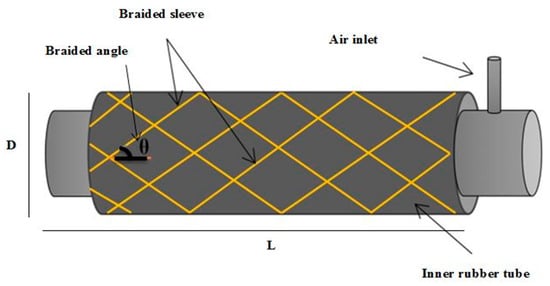
Figure 1.
The structure of the pneumatic muscle actuator.
Sárosi, et al. [40] set 25% as a maximum contraction ratio for the contraction PMA, however, the structure of the actuator, the specifications and the dimensions of the inner rubber tube effects on its value [28], as well as the maximum diameter of the braided sleeve. However, it is not more than 35% [15] [28]. On the other hand, the extensor PMA could be extended to more than 50% [4,27,41]. The contraction ratio and the extension ratios are defined in (1) and (2), respectively.
2.1. The Parallel Structure of Pneumatic Muscle Actuators
In this section, we designed and built two continuum arms by using either 4-contractor PMAs or 4-extensor PMAs, as shown in Figure 2.
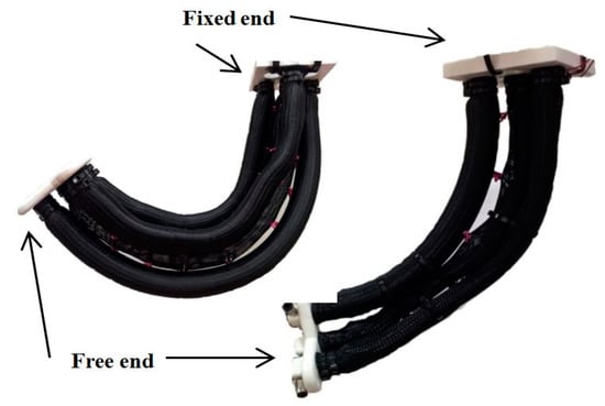
Figure 2.
The continuum arms at 300kPa. (Left) An extensor arm; (Right) A contractor arm.
Figure 2 (left arm) illustrates a continuum arm of four 30 cm extensor actuators, one in the centre and three set around it by 120° displacements. The central muscle acts as a backbone to the continuum arm and it provides an additional actuated force. This layout provides an elongation of 17 cm, which represents 56% of the un-actuated condition at 500 kPa air pressure in all air muscles. Connecting numerous extensor PMAs in parallel provides a bending behaviour. The actuators are fixing together along their entire length to form a continuum arm [13] by using a high tension thread. Increasing the pressure in any of corner actuator; establish a bending performance depends on the amount of P in the muscle and the attached weight. The bending behaviour for this structure occurs when the length is changed in one muscle more than in others.
The maximum angle at no load for the continuum arm under test was measured at 164°, while it reduced to 116° at 0.5 kg payload. On the other hand, Figure 2 (right arm) shows the soft robot arm of four 30 cm contractor actuators. This continuum arm is constructed in a similar way to the extensor soft arm. Table 1 lists the average maximum bending angle at different loads.

Table 1.
The maximum bending angle at different loads for the extensor and contractor soft arms.
Applying equal air pressure on all actuators simultaneously causes contraction by 30%, similar to the contraction ratio of a single contraction actuator. The bending behaviour could also be achieved by the constructed contraction arm, which provides a maximum bending angle of 84.3° at no load and 47° when the attached load is increased to 0.5 kg.
For both soft arms, the no pressure angle is set to (0°) and a 6-axis motion tracking (MPU 6050) sensor by (DFROBOT, Switzerland) is used and mounted to the free end to measure the bending angle at 500 kPa. And ultrasonic sensor (HC-SR04) by (ElecFreaks, Shenzhen, China) is attached to the bottom of the free end to measure the length of each arm. The load has been attached to the centre of the free robot end. The experiment for both arms is repeated five times to maintain the accuracy of the measurement and the average bending angles are listed in Table 1.
2.2. The Actuated Force for the Contraction and the Extension PMA
Numerous authors tested and modelled the force of pneumatic actuators, such as Tondu and Lopez [17], Chou and Hannaford [42], Davis, et al. [15], Godage, et al. [43] and Davis and Caldwell [44]. They have explained the main affected parameters on the tensile force of the contractor PMA. To explain the main performances of the contraction and the extension actuators used in this article, the actuated forces for both types of pneumatic actuators have been illustrated in Figure 3. For measuring the tensile force, the contraction actuator is fixed from one side, and the other side is attached to the fixed weight scale. The pressure is increased by 50 kPa steps from 0 to 500 kPa and at each step; the contraction actuator produces a tensile force with the effect of shortening the length. This experiment is repeated three times and the average force is plotted.
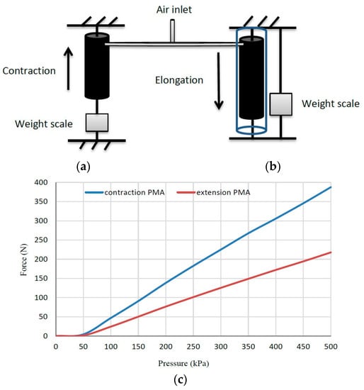
Figure 3.
The tensile force for the 30 cm contraction PMA and the compressive force for the 30 cm extension PMA. (a,b) The experiment schematic. (c) The force-pressure characteristics.
A similar procedure has been applied to the extensor actuator by increasing the air pressure step by step. At each point, the length of the actuator is raised and pulls the weight scale to a specific value. The extensor actuator is surrounded by a cylindrical tube to stop its buckling.
Figure 3 illustrates the experiment diagrammatically and it shows that the force of the contraction actuator almost doubles the force of the extension actuator with similar PMA dimensions.
This figure shows the force of single pneumatic actuators. while the force of the parallel structures in Figure 2 is almost quadruple the force of a single actuator [28].
3. Design and Construction of the Soft Arm
In this section, we have designed a new continuum arm based on the pneumatic muscle actuator, which has the ability to extend and bend. The proposed soft arm has been designed and built to provide multiple degree of freedoms (DoF) and performances based on the knowledge we have obtained from the designs and results in Section 2. It is designed to operate close to humans due to its softness and safe operation performances.
Designing any robot arm is subject to project requirements. The main objective of this project is to get a robot arm to pick up an object from the ground and move it to any position within 360° of the vertical robot arm axis. To achieve this objective, the following performances are required:
- The ability for length increment.
- The ability to bend in all directions.
- The arm force is big enough to pick up different objects.
Five extensor PMAs have been used to build the top section of the soft robot arm. The suggested structure of the top section provides a bending performance (as explained in Section 2), in addition to the elongation behaviour of the proposed arm.
The second section is made from five contractor actuators which offer a high tensile force and a contraction of about 30% of the reset length in addition to the bending behaviour, as shown above. The full design of the two sections of the proposed soft arm is illustrated in Figure 4.
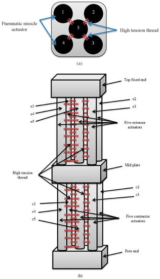
Figure 4.
The proposed soft arm. (a) The layout of actuator distributions. (b) The structure of the entire arm.
Using five actuators instead of three [45] increases the force of the robot arm for similar diameters [28]. The high-tension thread used to connect the corner actuators with the centre PMA longitudinally, performs the bending behaviour. The bending payload along the x-axis and along the y-axis is performed by two actuators that increase the bending force due to the parallel structure, as previously shown [28].
The extension segment has been made from identical 25 cm extensor PMAs, while the lower section is made from 30 cm contractor actuators. The length of the soft arm, including the fixed, the mid end, the free end and the end-effector bracket, is 72 cm. The cross section appears as a square of 10 cm in length, which represents the dimensions of the fixed and free ends.
The actuator’s caps are made from aluminium and the fixed, mid and free ends have been designed by Solidworks 2016 and built by a 3D printer using plastic material (see Figure 4a). The proposed continuum arm achieves the requirements above by reaching 12 cm elongation (elongation by increasing 48%) and a 117-degree full bending angle using both sections at no load. The weight of the contractor section is 0.2 kg and the weight of the end-effector support is 0.3 kg.
The Bending and Displacement Test of the Soft Arm
The bending performance of the proposed soft arm can be achieved by either pressurising one actuator (but not the centre PMA because the thread prevents its bending) in the top section, one in the bottom section or both. Other possibilities of bending could be achieved through a combination of either two, three or more PMAs, in both the top and the bottom sections. Referring to Figure 4a, the probable bending performances can be explained in Figure 5, where (e) refers to the extensor actuator and (c) refers to the contractor actuator. Figure 6 illustrates the bending angle of the free end in three patterns.
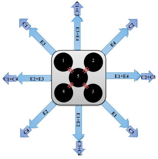
Figure 5.
Possible direction movements by pressurising one or two actuators in each section.
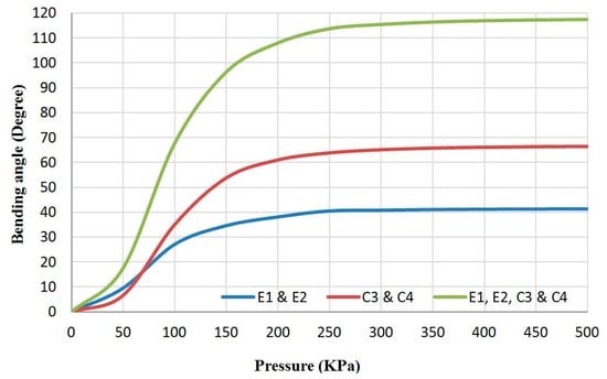
Figure 6.
The bending angle of the proposed soft arm due to three different pressurise patterns.
A pressure sensor (0–500 kPa) and an MPU 6050 sensor have been used to record both the air pressure and the bending angle at different air pressure values from zero to 500 kPa for three repetitions. The MPU 6050 sensor has been mounted onto the free end of the arm to measure the bending angle. The experiment is set by applying an air pressure via solenoid valve (Matrix MK754.8E1D2XX) by (MATRIX, Ivrea, Italy) by steps of 50 kPa which is controlled by microcontroller (Arduino mega 2560) by (Arduino, Ivrea, Italy).
In Figure 6, the bending angle of the extension segment is lower than the angle of the contraction segment due to the weight of both the bottom section and the end effector support, in addition to the reverse bending behaviour of the contraction part because of its material. On the other hand, the bending behaviour of the contraction part is similar to the bending of the contraction arm (Figure 2) at a 0.3 kg load, which represents the weight of the end-effector bracket. Pressurising two actuators in both the extension and the contraction sections simultaneously, produces a bending angle which is more than the summation of the separated operations.
Furthermore, activate the two sections simultaneously increases the displacement into x and y directions in addition to z, which increases with the bending.
4. The Modified Design of the Proposed Arm
In order to increase both the bending and the payload of the robot arm, we have used the self-bending contraction actuator (SBCA) by Al-Ibadi, et al. [46] instead of the simple contraction PMA. The bending angle for this type is more than the bending angle of the contraction section of the proposed robot arm (see Figure 4). Furthermore, the weight of the bottom section will be reduced by removing the centre actuator; this also decreases the controller parameters. The bending muscles are positioned to bend into the corners of the square plate. Figure 7 shows the new design of the proposed continuum arm with an ability to extend longitudinally and bend in all direction, and Figure 8 illustrates the bending of the new design by activating the same actuators as in Figure 6.
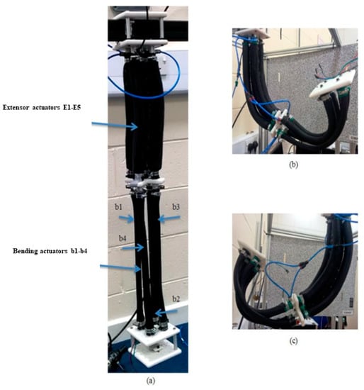
Figure 7.
The modified multi-function soft arm. (a) The arm at no pressure. (b,c) represent two different bending possibilities.
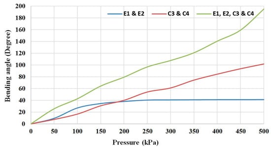
Figure 8.
The bending angle of the modified multi-function soft arm due to three different pressurised patterns.
5. Controlling the Presented Soft Arm
Controlling a system such as a soft continuum robot arm is a challenge due to: (i) the various motions performed, such as contraction, extension and bending; (ii) the nature of the material properties, including hysteresis and the viscos elastic behaviour; (iii) the unique performances for each design [47]. To control the presented continuum robot arm, two different strategies are applied.
5.1. Cascaded Position Control
The no-load position control of the free-end has been set by mapping the Cartesian coordinates of the end effector as a function of the air pressure in the five extensor PMAs and four SBCAs. Numerous patterns are applied in this experiment by pressurising one actuator at a time, or two actuators or more, until all of the actuators in the robot arm have been pressurised. The patterns are selected to cover all the probabilities by 50 kPa steps and for three repetitions. Each time the air pressure is increased from zero to 500 kPa, the position of the free-end is recorded.
In this experiment, two cameras (Pixy CMUcam5) by (CMUcam, Amazon, UK) have been used to track the 3D position of the arm. An Arduino MEGA 2560 by (Arduino, Ivrea, Italy) is also used in addition to the nine pressure sensors (0–500 kPa) and three Solenoid Valves (Matrix MK754.8E1D2XX) by (MATRIX, Ivrea, Italy).
The Pixy camera only tracks x and y positions for a predefined object. To solve this issue, two cameras have been used in two positions to get a 3D reading of the tracking object. A blue ball has been chosen as a tracking object and it is attached to the end of the robot arm so as to be seen as a blue circle at all times. Figure 9 explains the layout of the cameras and the ball.
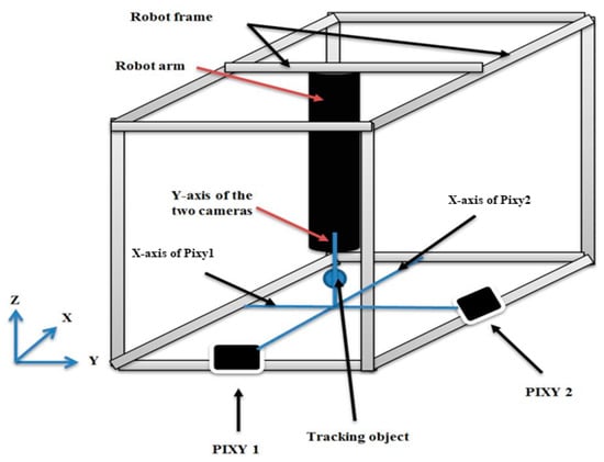
Figure 9.
The layout of the robot arm and the camera system.
The X-axis of Pixy1 and the X-axis of Pixy2 have been set at the Y-axis and X-axis of the robot arm, respectively. Meanwhile, the Y-axis of the two cameras has been set as the Z-axis of the robot arm, with the reference point at no pressure set to (0, 0, −720) mm.
The vision system provides 3D position data for mapping the robot’s movements and this data is used to train a neural network (NN) with 3-inputs and 9-outputs at mean square error (MSE) equal to 8.69 × 10⁻⁸. The NN configuration is implemented in Matlab and it provides the reverse information of the robot (inverse kinematics), where the inputs are the position of the robot and the outputs are the air pressures in the nine actuators.
The mapping data of x-y, x-z and y-z are illustrated in Figure 10a–c for different pressurising patterns in the nine actuators at pressure steps from 0 to 500 kPa. The results show non-symmetrical movements due to the difficulties of build a symmetrical continuum arm and the friction between the parallel actuators.
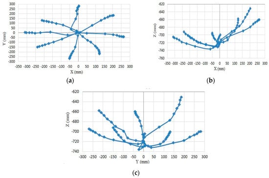
Figure 10.
Mapping of the movement data. (a) X-Y mapping. (b) X-Z mapping. (c) Y-Z mapping.
The pressure control has been applied to control the offline position of the soft arm at no load. Nine pairs of NN controllers are used to control the pressure in the nine actuators, where each pair contains two controllers for filling and venting the PMA, respectively. In each pair, the individual controller work depends on the error of air pressure. Figure 11 illustrates the flowchart of each pair.
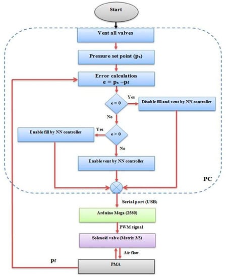
Figure 11.
The flowchart of single pair of neural network controllers.
The NN controller has been designed as the specification in previous work in [46] to fill or vent the actuator depending on the error of the pressure, and the model used in this system is the approximate relationship between the duty cycle of the controller output and the air pressure in the PMA as in (3), during 0.5 s steps.
where y is the pressure in kPa, the number (500) represents the maximum air pressure in kPa, u is the controlled duty cycle and the (98) refers to 98% of the maximum duty cycle for the control signal to avoid the continuous supply to the solenoid valve. Figure 12 shows the relation between the actuator air pressure and the duty cycle.
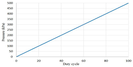
Figure 12.
The approximate relation between air pressure and duty cycle.
Using (3) as a model to train the NN controller instead of the trend line of the actual data does not affect the plant output, therefore, the approximate equation has been used.
The full block diagram of the cascaded position control system is shown in Figure 13 and a random pattern of movement is selected to validate the cascaded control system, as shown in Figure 14, starting from the initial point (0, 0, −720) mm. The pneumatic muscles for both sections are called PMA1 to PMA9 for the extensor muscles (e1, e2, e3, e4 and e5) and the bending muscles (b1, b2, b3 and b4) (see Figure 4 and Figure 7).
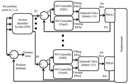
Figure 13.
The full block diagram of the cascaded position control system.
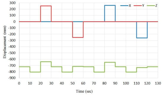
Figure 14.
A random pattern to validate the cascaded position control system.
In this pattern, we wanted to get movement along the X-axis by 260 mm and Y-axis by 252 mm; the z displacement is the result of these two actions. Therefore, the control system which is described in Figure 13 will control the pressure in all actuators to track the desired position pattern. The pressure outputs from the inverse identifier system and their feedback values have been illustrated in Figure 15, while Figure 16 shows the position set point and the position feedback at no-load, and Figure 17 shows the position error.
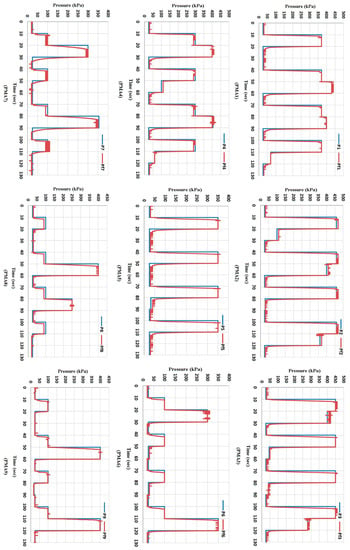
Figure 15.
The output and feedback air pressure for the nine actuators, which have been programmed to control the position of the multi-function soft arm at no-load by using the cascaded control system.
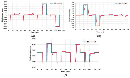
Figure 16.
The desired feedback position for the multi-function soft arm by the cascaded control system. (a) The x position. (b) The y position and (c) is the z position.
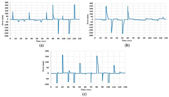
Figure 17.
The error of x, y, z displacements, respectively (a) The x position error. (b) The y position error and (c) is the z position error.
According to Figure 15, the pressure control has been fulfilling the controller requirements, where the error is set to be (±5 kPa) to increase the stability of the controller system by increasing the gap between the filling and venting controllers for each actuator. According to the sign of the pressure error, a switch is designed to select either the filling or venting controller. While the air pressure is under the closed loop control, the position in this cascaded system is under an open loop control system.
Figure 16 and Figure 17 show the desired x, y and z displacements and the feedback data from the cascaded control system at no-load and the error, respectively. It is clear that there is no correction to y when the x changes, and vice versa. Furthermore, in a load condition, the pressure control will work properly while the position will present a high error.
5.2. Closed-Loop Position Control of the Modified Multi-Function Soft Arm
A large amount of data has been used to map the movement of the soft arm by pressurising the 9-actuators into different patterns and repeating these values several times. Due to the softness, nonlinearity and hysteresis of the PMA, the positions at similar pressure patterns differ each time, and that makes the inverse identifier system not accurate enough, which causes an error in position even at no-load.
Due to the unique design of the proposed soft arm, the pressure in each muscle effects the position of the end effector significantly. Consequently, a suitable control algorithm has to be applied to solve the position control under load conditions.
According to Figure 5 and Figure 10, the movement of the extension section covers 360° at displacement up to an average of 260 mm in all directions, which can represent a base joint for the robot arm. On the other hand, pressurising the bottom section causes a movement toward the z-axis by about 150 mm (see Figure 5, Figure 8 and Figure 10).
An infinitive degree of freedom and the numbers of base joints make the motion planning for the robot arm quite difficult since the search space will be large, as it is exponential in the number of robot joints [48]. To reduce these difficulties, another classification might be present for the arm joints according to the active actuator in section one.
At the beginning, a certain task is asked of the robot arm, such as grasping objects of different weights each time and moving them to a specific position in space by selecting a suitable path. This plane can be generated and then executed by applying a suitable control system [49].
In the case of the proposed continuum arm, both the joint classification and the motion plan have been explained in Figure 18, which only shows the motion by the extension section.
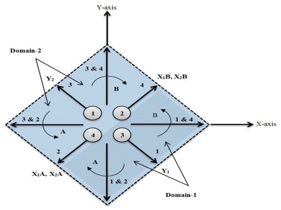
Figure 18.
Joints and motion of the extension section.
Assuming that each muscle represents a joint, the robot arm will move towards the arrows (1, 2, 3 and 4) when one actuator (single joint) has been activated. The motion starts from the initial point P0 (0, 0) into points P1 (125, −229), P2 (−249, −157), P3 (−224, 135) and P4 (213, 189) (see Figure 10) by an approximately straight line, and its displacement depends on the amount of air pressure, which varies from 0 kPa to 500 kPa.
Referring to Figure 18, domain-1 illustrates the motion of the continuum arm by activating the actuators 1, 2 and 4 (joints 1, 2 and 4), which represents 50% of the full motion of the robot arm due to the top section. Domain-2 shows the motion due to the extension actuators 3, 2 and 4 (joints 3, 2 and 4), and that is the other half of the robot motion. Figure 19 shows the movement of the three joints in domain-1, according to the explanation above.
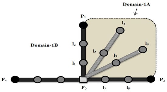
Figure 19.
The top view of the three joint movements of actuators 1, 2 and 4 at x-y plan.
Applying air pressure to the extensor PMA1, drawing a path from P0 to P1 through l1 and l2 at zero pressure in PMA2 and PMA4 while pressurising PMA2, leads to moving the robot arm toward P2 through l7 and l8. The rest of the l-points refer to the other locations of the robot arm due to different pressurising conditions for PMA1 and PMA2.
According to Figure 18 and Figure 19, the following position control algorithm is proposed for the soft robot arm under study:
Assign y-axis to actuators 1 and 3 as follows:
- Actuator 1 covers y values at domain-1 and defines as Y1.
- Actuator 3 covers y values at domain-2 and defines as Y2.
- If the desired position point locates under Y1; the PMA2 and PMA4 define as:
- Actuator 2 covers x-values at domain-1A and defines as X1A.
- Actuator 4 covers x-values at domain-1B and defines as X1B.
- If the desired position point locates under Y2; the PMA2 and PMA4 define as:
- Actuator 2 covers x-values at domain-2A and defines as X2A.
- Actuator 4 covers x-values at domain-2B and defines as X2B.
While the bottom section is built from bending-contraction actuators which provide bending behaviour effects directly to the z-direction of the robot arm, these PMAs have been classified into two pairs to work together and control the z-position as the following:
- If the desired position point locates under Y1, bending-actuator3 and bending-actuator4 pressurise simultaneously.
- If the desired position point locates under Y2, bending-actuator1 and bending-actuator2 pressurise simultaneously.
The length’s increment of the proposed soft arm is considered to be a special motion at the origin of the x-y plan. To achieve this movement the controller applies equally suitable values of air pressure to all 5-actuators in the extension section at the same time.
The layout of the soft robot arm and the pixy cameras have been used (see Figure 9) to control the position of the end-effector according to the block diagram in Figure 20.
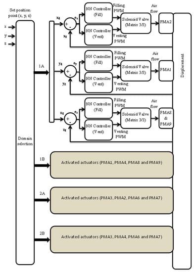
Figure 20.
The full block diagram of the closed loop position control system.
The algorithm distributes the axes to the actuators and provides an easy and effective strategy to control the position of the soft robot arm at any load condition. The controller system in Figure 20 has been applied to an example of movement from the initial point (0, 0, −720) to the target point (−30, −120, −650) at three load conditions (no-load, 300 g and 500 g) and for three repetitions at acceptable accuracy as in Figure 21. Moreover, this motion used four actuators (PMA1, PMA2, PMA8 and PMA9), while other motions could use other combinations of actuators but under the algorithm above.
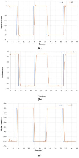
Figure 21.
The reference and the feedback positions at 300 g. (a) Is the X and Xf position. (b) Is the Y and Yf position. And (c) Is the Z and Zf position.
The results of this experiment have been illustrated in Figure 21 and Figure 22, and since changing the air pressure in PMA1, not only affects the y-position but also both the x and z positions. Therefore, each time the controller of PMA1 tries to track the desired position on y, the controller of PMA2 changes the pressure of the (x) actuator to track x and the controller of the bending actuators adjusts the pressure of the (z) actuators to correct the z-position.
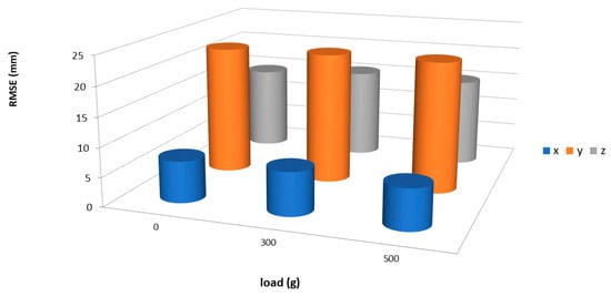
Figure 22.
The RMSE for the position control at three different load conditions.
This is useful if the x-controller will first affect the y and z positions, and the z-controller affects the x and y controller.
The maximum air pressure in the activated actuators is listed in Table 2 at different load conditions and it is clear that the air pressure is increased when the load is increased.

Table 2.
The maximum pressure in kPa in the activated actuators at different load values.
Figure 21 shows the tracking of x, y and z at 300 g with low steady state error, which proves the quality of the presented algorithm and the closed loop controller. The root mean square error (RMSE) for no-load, 300 g, and for 500 g is shown in Figure 22. While the maximum applied air pressure has been listed in Table 2, it rises with the increment in load to increase the payload for the soft robot arm.
6. Conclusions
The basic construction of McKibben’s pneumatic muscle actuator (PMA) has been explained in this article. Furthermore, the actuated force for samples of both types of PMA have illustrated that the tensile force of the contraction actuator is about double the amount of the force of the compressive PMA at similar actuator size and material specifications.
Moreover, four extensor PMAs have been laid in parallel to explain the bending behaviour of multi extensor actuators. The bending could be achieved by a structure parallel to the contraction PMA. A new continuum arm structure is proposed by using both types of actuators as two sections of the soft robot arm. The first section has been made from five extensor PMAs while the bottom section is made from five contractor air actuators. This design provides special performances of this type of robot arm, such as elongation, contraction, bending by single or both sections towards all directions.
A modified design of the presented continuum arm has been implemented by replacing the five (simple) contraction actuators in the bottom section with four self-bending contraction actuators (SBCA) to reduce the number of actuators and enhance the bending performance. A full mapping of its movement is then illustrated. A cascaded position control has been applied by using inverse model identification and a valuable closed-loop neural network (NN) controller for air pressure. This method shows the ability to achieve a specific position in the space at no load of the proposed soft arm.
A new position control algorithm has been proposed from the mapping data and moving performances of the presented continuum arm. This algorithm distributes the x-axis and y-axis on corner actuators of the top section and the z-axis on the two pairs of the bending-contraction actuators in the bottom section.
A specific layout of two PIXY cameras is explained to get three-dimensional data from the free-end of the continuum arm by using the two-dimensional output of the camera. The proposed algorithm and the feedback from the vision system are used to design and apply an efficient closed-loop position control of the presented continuum arm at different load conditions.
Numerous applications can be achieved by using the proposed continuum arm in its modified version, such as manufacture food processing and as a classification robot arm, can pick up objects and move them depending on their colour, weight or shape by using specific end-effectors and sensors.
As a future work, two continuum arms could be designed and implemented to perform task sharing for a multi-robot system and a collaborative control system might be applied to achieve this task.
Author Contributions
A.A.-I. designed and performed the experiments; A.A.-I. and S.D. analysed the data; A.A.-I. wrote the paper; and S.N.-M. and T.T edited the paper.
Funding
This research received no external funding.
Acknowledgments
The authors would like to thank the Ministry of Higher Education (Iraq), University of Basrah, Computer-Engineering Department for providing scholarship support to the first author of this paper.
Conflicts of Interest
The authors declare no conflict of interest.
References
- Godage, I.S.; Branson, D.T.; Guglielmino, E.; Caldwell, D.G. Pneumatic muscle actuated continuum arms: Modelling and experimental assessment. In Proceedings of the 2012 IEEE International Conference on Robotics and Automation (ICRA), Saint Paul, MN, USA, 14–18 May 2012; pp. 4980–4985. [Google Scholar]
- Bartow, A.; Kapadia, A.; Walker, I. A novel continuum trunk robot based on contractor muscles. In Proceedings of the 12th WSEAS International Conference on Signal Processing, Robotics, and Automation, Cambridge, UK, 20–22 February 2013; pp. 181–186. [Google Scholar]
- McMahan, W.; Jones, B.A.; Walker, I.D. Design and implementation of a multi-section continuum robot: Air-Octor. In Proceedings of the 2005 IEEE/RSJ International Conference on Intelligent Robots and Systems, Edmonton, AB, Canada, 2–6 August 2005; pp. 2578–2585. [Google Scholar]
- McMahan, W.; Chitrakaran, V.; Csencsits, M.; Dawson, D.; Walker, I.D.; Jones, B.A.; Pritts, M.; Dienno, D.; Grissom, M.; Rahn, C.D. Field trials and testing of the OctArm continuum manipulator. In Proceedings of the 2006 IEEE International Conference on Robotics and Automation, Orlando, FL, USA., 15–19 May 2006; pp. 2336–2341. [Google Scholar]
- Kelasidi, E.; Andrikopoulos, G.; Nikolakopoulos, G.; Manesis, S. A survey on pneumatic muscle actuators modeling. In Proceedings of the 2011 IEEE International Symposium on Industrial Electronics (ISIE), Gdansk, Poland, 27–30 June 2011; pp. 1263–1269. [Google Scholar]
- Ranjan, R.; Upadhyay, P.; Kumar, A.; Dhyani, P. Theoretical and Experimental Modeling of Air Muscle. Int. J. Emerg. Technol. Adv. Eng. 2012, 2, 112–119. [Google Scholar]
- Wickramatunge, K.C.; Leephakpreeda, T. Study on mechanical behaviors of pneumatic artificial muscle. Int. J. Eng. Sci. 2010, 48, 188–198. [Google Scholar] [CrossRef]
- Leephakpreeda, T. Fuzzy logic based PWM control and neural controlled-variable estimation of pneumatic artificial muscle actuators. Expert Syst. Appl. 2011, 38, 7837–7850. [Google Scholar] [CrossRef]
- Jamwal, P.K.; Xie, S.Q. Artificial Neural Network based dynamic modelling of indigenous pneumatic muscle actuators. In Proceedings of the 2012 IEEE/ASME International Conference on Mechatronics and Embedded Systems and Applications (MESA), Suzhou, China, 8–10 July 2012; pp. 190–195. [Google Scholar]
- Kang, B.-S.; Kothera, C.S.; Woods, B.K.; Wereley, N.M. Dynamic modeling of Mckibben pneumatic artificial muscles for antagonistic actuation. In Proceedings of the IEEE International Conference on Robotics and Automation, Kobe, Japan, 12–17 May 2009; pp. 182–187. [Google Scholar]
- Trivedi, D.; Rahn, C.D.; Kier, W.M.; Walker, I.D. Soft robotics: Biological inspiration, state of the art, and future research. Appl. Bionics Biomech. 2008, 5, 99–117. [Google Scholar] [CrossRef]
- Zheng, T.; Branson, D.T., III; Kang, R.; Cianchetti, M.; Guglielmino, E.; Follador, M.; Medrano-Cerda, G.A.; Godage, I.S.; Caldwell, D.G. Dynamic continuum arm model for use with underwater robotic manipulators inspired by octopus vulgaris. In Proceedings of the 2012 IEEE International Conference on Robotics and Automation (ICRA), Saint Paul, MN, USA, 14–18 May 2012; pp. 5289–5294. [Google Scholar]
- Godage, I.S.; Walker, I.D. Dual Quaternion based modal kinematics for multisection continuum arms. In Proceedings of the 2015 IEEE International Conference on Robotics and Automation (ICRA), Seattle, WA, USA, 26–30 May 2015; pp. 1416–1422. [Google Scholar]
- Anh, H.P.H. Online tuning gain scheduling MIMO neural PID control of the 2-axes pneumatic artificial muscle (PAM) robot arm. Expert Syst. Appl. 2010, 37, 6547–6560. [Google Scholar] [CrossRef]
- Davis, S.; Tsagarakis, N.; Canderle, J.; Caldwell, D.G. Enhanced modelling and performance in braided pneumatic muscle actuators. Int. J. Robot. Res. 2003, 22, 213–227. [Google Scholar] [CrossRef]
- Thanh, T.D.C.; Ahn, K.K. Nonlinear PID control to improve the control performance of 2 axes pneumatic artificial muscle manipulator using neural network. Mechatronics 2006, 16, 577–587. [Google Scholar] [CrossRef]
- Tondu, B.; Lopez, P. Modeling and control of McKibben artificial muscle robot actuators. IEEE Control Syst. 2000, 20, 15–38. [Google Scholar]
- Szepe, T. Accurate force function approximation for pneumatic artificial muscles. In Proceedings of the 3rd IEEE International Symposium on Logistics and Industrial Informatics (LINDI), Budapest, Hungary, 25–27 August 2011; pp. 127–132. [Google Scholar]
- Nakamura, T.; Shinohara, H. Position and force control based on mathematical models of pneumatic artificial muscles reinforced by straight glass fibers. In Proceedings of the 2007 IEEE International Conference on Robotics and Automation, Roma, Italy, 10–14 April 2007; pp. 4361–4366. [Google Scholar]
- More, M.; Líška, O. Comparison of different methods for pneumatic artificial muscle control. In Proceedings of the IEEE 11th International Symposium on Applied Machine Intelligence and Informatics (SAMI2013), Herl’any, Slovakia, 31 January–2 February 2013; pp. 117–120. [Google Scholar]
- Andrikopoulos, G.; Nikolakopoulos, G.; Manesis, S. Advanced Nonlinear PID-Based Antagonistic Control for Pneumatic Muscle Actuators. IEEE Trans. Ind. Electron. 2014, 61, 6926–6937. [Google Scholar] [CrossRef]
- Yang, Q.; Zhang, L.; Bao, G.; Xu, S.; Ruan, J. Research on novel flexible pneumatic actuator FPA. In Proceedings of the 2004 IEEE Conference on Robotics, Automation and Mechatronics, Singapore, 1–3 December 2004; pp. 385–389. [Google Scholar]
- Neppalli, S.; Jones, B.; McMahan, W.; Chitrakaran, V.; Walker, I.; Pritts, M.; Csencsits, M.; Rahn, C.; Grissom, M. Octarm-a soft robotic manipulator. In Proceedings of the IEEE/RSJ International Conference on Intelligent Robots and Systems, San Diego, CA, USA, 29 October–2 November 2007; p. 2569. [Google Scholar]
- Neppalli, S.; Jones, B.A. Design, construction, and analysis of a continuum robot. In Proceedings of the IEEE/RSJ International Conference on Intelligent Robots and Systems, San Diego, CA, USA, 29 October–2 November 2007; pp. 1503–1507. [Google Scholar]
- Giannaccini, M.E.; Xiang, C.; Atyabi, A.; Theodoridis, T.; Nefti-Meziani, S.; Davis, S. Novel design of a soft lightweight pneumatic continuum robot arm with decoupled variable stiffness and positioning. Soft Robot. 2018, 5, 54–70. [Google Scholar] [CrossRef] [PubMed]
- Robinson, G.; Davies, J.B.C. Continuum robots-a state of the art. In Proceedings of the IEEE International Conference on Robotics and Automation, Detroit, MI, USA, 10–15 May 1999; pp. 2849–2854. [Google Scholar]
- Al-Ibadi, A.; Nefti-Meziani, S.; Davis, S. Design, implementation and modelling of the single and multiple extensor pneumatic muscle actuators. Syst. Sci. Control Eng. 2018, 6, 80–89. [Google Scholar] [CrossRef]
- Al-Ibadi, A.; Nefti-Meziani, S.; Davis, S. Efficient structure-based models for the McKibben contraction pneumatic muscle actuator: the full description of the behaviour of the contraction PMA. Actuators 2017, 6, 32. [Google Scholar] [CrossRef]
- Razif, M.R.M.; Bavandi, M.; Nordin, I.N.A.M.; Natarajan, E.; Yaakob, O. Two chambers soft actuator realizing robotic gymnotiform swimmers fin. In Proceedings of the IEEE International Conference on Robotics and Biomimetics (ROBIO), Bali, Indonesia, 5–10 December 2014; pp. 15–20. [Google Scholar]
- Razif, M.; Rusydi, M.; Elango, N.; Nordin, M.; Aimi, I.N.; Faudzi, M.; Athif, A. Non-linear finite element analysis of biologically inspired robotic fin actuated by soft actuators. Appl. Mech. Mater. 2014, 528, 272–277. [Google Scholar] [CrossRef]
- Natarajan, E.; Faudzi, M.; Athif, A.; Jeevanantham, V.M.; Razif, M.; Rusydi, M.; Nordin, M.; Aimi, I.N. Numerical Dynamic Analysis of a Single Link Soft Robot Finger. Appl. Mech. Mater. 2014, 459, 449–454. [Google Scholar] [CrossRef]
- Wang, B.; Aw, K.C.; Biglari-Abhari, M.; McDaid, A. Design and fabrication of a fiber-reinforced pneumatic bending actuator. In Proceedings of the IEEE International Conference on Advanced Intelligent Mechatronics (AIM), Banff, AB, Canada, 12–15 July 2016; pp. 83–88. [Google Scholar]
- Nordin, I.N.A.M.; Razif, M.R.M.; Natarajan, E.; Iwata, K.; Suzumori, K. 3-D finite-element analysis of fiber-reinforced soft bending actuator for finger flexion. In Proceedings of the IEEE/ASME International Conference on Advanced Intelligent Mechatronics (AIM), Wollongong, Australia, 9–12 July 2013; pp. 128–133. [Google Scholar]
- Faudzi, A.A.M.; Razif, M.R.M.; Nordin, I.N.A.M.; Suzumori, K.; Wakimoto, S.; Hirooka, D. Development of bending soft actuator with different braided angles. In Proceedings of the 2012 IEEE/ASME International Conference on Advanced Intelligent Mechatronics (AIM), Kachsiung, Taiwan, 11–14 July 2012; pp. 1093–1098. [Google Scholar]
- Melingui, A.; Lakhal, O.; Daachi, B.; Mbede, J.B.; Merzouki, R. Adaptive neural network control of a compact bionic handling arm. IEEE/ASME Trans. Mechatron. 2015, 20, 2862–2875. [Google Scholar] [CrossRef]
- Melingui, A.; Merzouki, R.; Mbede, J.B.; Escande, C.; Daachi, B.; Benoudjit, N. Qualitative approach for inverse kinematic modeling of a compact bionic handling assistant trunk. In Proceedings of the 2014 International Joint Conference on Neural Networks (IJCNN), Beijing, China, 6–11 July 2014; pp. 754–761. [Google Scholar]
- Melingui, A.; Escande, C.; Benoudjit, N.; Merzouki, R.; Mbede, J.B. Qualitative approach for forward kinematic modeling of a compact bionic handling assistant trunk. IFAC Proc. Volumes 2014, 47, 9353–9358. [Google Scholar] [CrossRef]
- Lakhal, O.; Melingui, A.; Merzouki, R. Hybrid approach for modeling and solving of kinematics of a compact bionic handling assistant manipulator. IEEE/ASME Trans. Mechatron 2016, 21, 1326–1335. [Google Scholar] [CrossRef]
- Tate, J.S.; Kelkar, A.D.; Whitcomb, J.D. Effect of braid angle on fatigue performance of biaxial braided composites. Int. J. Fatigue 2006, 28, 1239–1247. [Google Scholar] [CrossRef]
- Sárosi, J.; Bíró, I.; Németh, J.; Cveticanin, L. Dynamic modeling of a pneumatic muscle actuator with two-direction motion. Mech. Mach. Theory 2015, 85, 25–34. [Google Scholar] [CrossRef]
- Al-Ibadi, A.; Nefti-Meziani, S.; Davis, S. 3D position mapping of continuum arm. In Proceedings of the International Conference for Students on Applied Engineering (ICSAE), Newcastle upon Tyne, UK, 20–21 October 2016; pp. 1–6. [Google Scholar]
- Chou, C.-P.; Hannaford, B. Measurement and modeling of McKibben pneumatic artificial muscles. IEEE Trans. Robot. Autom. 1996, 12, 90–102. [Google Scholar] [CrossRef]
- Godage, I.S.; Branson, D.T.; Guglielmino, E.; Medrano-Cerda, G.A.; Caldwell, D.G. Dynamics for biomimetic continuum arms: A modal approach. In Proceedings of the 2011 IEEE International Conference on Robotics and Biomimetics (ROBIO), Karon Beach, Thailand, 7–11 December 2011; pp. 104–109. [Google Scholar]
- Davis, S.; Caldwell, D.G. Braid effects on contractile range and friction modeling in pneumatic muscle actuators. Int. J. Robot. Res. 2006, 25, 359–369. [Google Scholar] [CrossRef]
- Walker, I.D.; Dawson, D.M.; Flash, T.; Grasso, F.W.; Hanlon, R.T.; Hochner, B.; Kier, W.M.; Pagano, C.C.; Rahn, C.D.; Zhang, Q.M. Continuum robot arms inspired by cephalopods. Defense Secur. 2005, 5804, 303–314. [Google Scholar]
- Al-Ibadi, A.; Nefti-Meziani, S.; Davis, S. Active soft end effectors for efficient grasping and safe handling. IEEE Access 2018, 6, 23591–23601. [Google Scholar] [CrossRef]
- Thuruthel, T.G.; Ansari, Y.; Falotico, E.; Laschi, C. Control Strategies for Soft Robotic Manipulators: A Survey. Soft Robot. 2018, 5, 149–163. [Google Scholar] [CrossRef] [PubMed]
- Choi, J.; Amir, E. Factor-guided motion planning for a robot arm. In Proceedings of the IEEE/RSJ International Conference on Intelligent Robots and Systems, San Diego, CA, USA, 29 October–2 November 2007; pp. 27–32. [Google Scholar]
- Latombe, J.-C. Robot Motion Planning; Springer Science & Business Media: Berlin, Germany, 2012. [Google Scholar]
© 2018 by the authors. Licensee MDPI, Basel, Switzerland. This article is an open access article distributed under the terms and conditions of the Creative Commons Attribution (CC BY) license (http://creativecommons.org/licenses/by/4.0/).