1. Introduction
Autonomous multi-robot systems are good candidates for extraterrestrial mission scenarios. NASA has several missions in extraterrestrial areas. For instance, the missions Mars Exploration Rover [
1] and Mars Science Lab NASA [
2] deal mainly with the exploration of the planet’s surface and the analysis of what the surface consists of. The robots are able to take surface samples by using a drill and take them back to a base station for later analysis. In the future, the autonomy of robots in planetary missions will become an almost mandatory requirement. Besides, a team of heterogeneous robots can speed up the missions enormously if different robots are optimized for certain tasks. Furthermore, a distributed team organization is recommended to avoid a single point of failure, which might result in a failed mission.
In this paper, we present the final results of the research project Integrated Mission Planning for Distributed Robot Systems (IMPERA). In the project, a team of heterogeneous robots had to explore a simulated lunar environment and collect lunar soil samples. The main goal was the development of a mission planning and execution architecture for autonomous control of a team of heterogeneous exploration robots.
An IMPERA mission starts with a coordinated search, where the robots explore an unknown area and try to find specific samples on the lunar surface. Additionally, the team has to transport all of the samples to a collection point. The team is coordinated in a distributed way, which is defined by the IMPERA project. The communication channel is assumed to be unreliable during the mission. Thus, the robots should be able to perform their tasks autonomously without communication for certain time intervals and to continue the coordinated behavior when the communication link is reestablished. In this paper, a basic robot behavior is called a “skill”. All skills of the robots are defined using our coordination language A Language for Interactive Agents (ALICA) [
3]. The mission is guided by the planning system Reactive Planning Engine for Multi-Agent Systems (pRoPhEt MAS) [
4]. The control center starts the mission interactively by defining the goal state using a logic description. From the goal specification, pRoPhEt MAS will generate a suitable ALICA plan. The control center is able to accept, decline or even modify this plan. If the plan fails, pRoPhEt MAS will suggest automatically a new suitable plan.
Details on the definition of robot skills and some intermediate results of IMPERA were presented in the publication “Towards Coordinated Multirobot Missions for Lunar Sample Collection in an Unknown Environment” [
5]. The main contribution of this paper is the integration of a modular, powerful and intuitive planning engine. Hence, we expand the formal language of ALICA and integrate a logic description to enable planning. Furthermore, we realize a generic task allocation using utilities. Finally, we optimize the planning step by parallel computing.
The remainder of this paper is organized as follows. In the next section, we outline briefly our robot platform. Project requirements are presented in
Section 3.
Section 4 is devoted to the discussion of related works. In
Section 5, we introduce the basic software architecture.
Section 6 presents the robot communication and coordination. Furthermore, in
Section 6.4, we specify the basic skills of the robots. The planning engine pRoPhEt MAS is presented in
Section 7. The evaluation of pRoPhEt MAS by means of three different scenarios is given in
Section 8. Finally, the work is concluded in
Section 9.
2. Robots
Our robot team consists of the three different robots, as shown in
Figure 1.
Figure 1.
The three types of robots used in Integrated Mission Planning for Distributed Robot Systems (IMPERA). (Left) The mobile robot Stummel with a manipulator arm, 2D LiDAR and color camera. (Middle) The Scout robot equipped with 2D LiDAR and color camera. (Right) The mobile robot Amparo with a manipulator arm and 3D perception unit.
All three systems are based on the Pioneer 3-AT platform from Adept (
http://www.mobilerobots.com). Because no robot is equipped with a drill, we simplify the mission by assuming that the drill samples are contained in containers distributed over the unknown environment where the team has to find and pick up these samples.
Robot Stummel is equipped with a 2D LiDAR system (Hokuyo UTM-30LX, Osaka, Japan) for the exploration task. Additionally, a 2D color camera (Point Grey Flea with a resolution of 1024 × 768 pixel) is used to locate and detect potential objects that have to be transported during the second phase of the mission. The computation unit is an embedded Intel I7 dual core processing unit with 3.2 GHz and wireless communication capabilities. Stummel has an integrated six-degrees-of-freedom (6-DOF) manipulator attached onto the mobile base, developed by Kinova (Boisbriand, QC, Canada). During the mission, Stummel has the task of generating a map of the operation area, locating and identifying the potential positions and transporting the drill samples. Robot Scout is equipped with a 2D LiDAR system (Hokuyo UTM-30LX, Osaka, Japan) for the exploration task. Similar to Stummel, this robot uses a 2D color camera (Point Grey Guppy C36 with a resolution of 752 × 480 pixels, Richmond, BC, Canada) to locate and identify potential object candidates. For computation, Scout uses an embedded Intel I7 dual core processing unit with 2.66 GHz and wireless communication. During the mission, Scout primarily has the task of generating a map of the operation area, as well as locating and identifying the potential positions of the sample containers. This robot is not able to transport objects. Robot Amparo is equipped similar to Stummel. It has additional sensors for 3D perception. The 3D LiDAR system consists of a 2D laser range finder (Hokuyo UTM-30LX with 30-m range, Osaka, Japan) and a Direct Perception DP-46 pan-tilt unit. Furthermore, Amparo is equipped with a stereo vision system with two color cameras. In the IMPERA mission, Amparo has the same capabilities as Stummel, but it uses 3D sensing to determine a more precise position of the samples. For localization and obstacle avoidance, Amparo uses a Sick LMS-111 laser (Düsseldorf, Germany).
The IMPERA demonstration is done in a flat area, to reduce the complexity of the project. Hence, the 2D LiDAR system of Stummel and Scout are suitable for the IMPERA scenario.
3. Requirements
The goal of project IMPERA is to realize a lunar mission scenario, simulated on Earth, using a team of autonomous and heterogeneous robots. The requirements for IMPERA missions can be summarized as:
multi-robot mission planning,
unreliable communication,
coordinated exploration and mapping,
object perception, localization and transportation with application to a lunar mission.
A team of autonomous heterogeneous mobile robots requires a suitable and intuitive description of team activities instead of providing only single agent programs [
6]. Task allocation and coordination should be dynamic instead of using predefined task-specific mapping to certain robots. Additionally, the description must be compatible with planning systems. The communication bandwidth is limited and unreliable. The team still should be able to cope with the unreliable communication. Moreover, the team has to explore and map an unknown environment collaboratively under unreliable communication. Finally, the team should be able to perceive drill samples, localize them in the mapped environment and carry them to the collection point.
4. Related Work
The Mars Exploration Rovers (MER) Mission has the goal to explore the surface of the planet Mars. The work in [
7] shows an overview of the rover technology and describes the relevant mission scenarios. The software of MER is based on the CLARAty software system. IMPERA realizes, similar to MER, an exploration of unknown environments. However, the software system CLARAty is controlled by a central system, while the IMPERA solution is based on decentralized control.
ALICA [
3] is a language to model the activities of a team of robots similar to CLARAty. The language is suitable for heterogeneous robots, works in dynamic environments using a low communication bandwidth and organizes the robots in a completely decentralized way. Furthermore, ALICA features functionality for task allocation and cooperation. Finally, ALICA is based on a formal language using a logic that facilitates the integration of planning systems.
Brenner and Nebel introduced the language MAPL (Multiagent Planning Language) [
8] for describing a continual planning algorithm realized with MAPL. For a proof-of-concept, they evaluate MAPL in the grid world domain. A small team consisting of four robots must find its positions on the grid. This evaluation is done by simulation only.
Nissim
et al. [
9] developed a distributed planning system that uses a heuristic forward search. This framework is evaluated in different international planning competitions. The main disadvantage is that the communication effort increases rapidly as the number of agents increases.
Burns
et al. [
10] developed parallel versions of best-first search to harness modern multicore machines. They showed that a set of previously-proposed algorithms for parallel best-first search can be much slower than running the well-known search algorithm A* sequentially. They presented a hashing function for parallel retracting A* (called PRA*) that takes advantage of the locality of a search space and gives superior performance. They also presented another algorithm, PBNF, which approximates a best-first search ordering while trying to keep all threads busy.
5. System Architecture
Figure 2 shows an overview of the system architecture of IMPERA. On top of the framework is the “LebtClient”, which is used to observe and control the team behavior. The control is done by defining a goal description via the command user interface. The planning engine pRoPhEt MAS creates a plan for the team, which will be executed. The actual status can be observed with the LebtClient.
In multi-agent systems, communication is an important prerequisite for robot cooperation. In the IMPERA mission, the robots have to explore and map an unknown lunar environment by using a cooperative SLAM (simultaneous localization and mapping) approach [
11]. We have to guarantee that the concurrently-created maps will be shared with all team members. However, communication is a critical factor. The robots might lose the communication link during the exploration. Hence, we are using DDS (Data Distribution Service) [
12] to decouple the communication; DDS is deployed on all robots.
Figure 2.
System architecture for IMPERA.
Figure 2.
System architecture for IMPERA.
The robot software framework is based on the popular and widely-used ROS middleware (Robot Operating System,
http://www.ros.org/). If a robot loses the connection to its teammates, DDS will buffer all messages, which are sent via the “ROS Proxy”. These messages will be passed on time-delayed when the connection is reestablished. Moreover, the communication module offers to send messages via DDS or UDP. In some cases, it is not necessary to use DDS and to store the sent data, because old information is not useful anymore. For example, if we are interested only in the current robot positions, we do not need to store outdated positions via DDS.
Every participating robot uses the same software as shown in
Figure 2. Every robot is able to create plans and execute these via ALICA. All sensor information collected during the mission will be stored in a so-called shared “WorldModel”. The world model information is shared with all teammates by using the “ROS Proxy”. Every robot integrates this information in its local copy of the shared WorldModel. In the IMPERA mission, the robots share the robot positions, map information, found drill samples and invalid sample candidates. The shared WorldModel represents the basic knowledge to coordinate the team activities.
6. Multirobot Communication and Coordination
6.1. ALICA
ALICA provides modeling features for cooperative behaviors with clear operational semantics. Furthermore, the language can be used in highly dynamic domains [
6]. Let us start to give an overview for how multi-agent plans can be defined. The core elements of the language are:
Basics:
- -
: Language describes the agents’ belief with a set of predicates and a set of function symbols
- -
: Set of roles, which the agent can take
- -
: Set of atomic behaviors, which can interact with the environment
- -
: Set of cooperative behavior description/plan
- -
: Set of alternative plans
- –
: Every task describes a function in a plan
- -
: States exists in plans and represents a step in that plan
Plan elements:
- –
Behaviors (atomic single-agent action programs)
- –
Plans (abstract multi-agent activity descriptions)
- –
Plantypes (sets of alternative plans defined by PlanTypes)
- –
Tasks (denote specific activities within plans defined by Tasks)
- –
Roles (descriptions of capabilities)
Conditional elements:
- –
Pre (denotes a pre-condition of a behavior or plan defined by Pre)
- –
Run (denotes a runtime condition of a behavior or plan defined by Run)
- –
Post (denotes a post-condition of a state defined by Post)
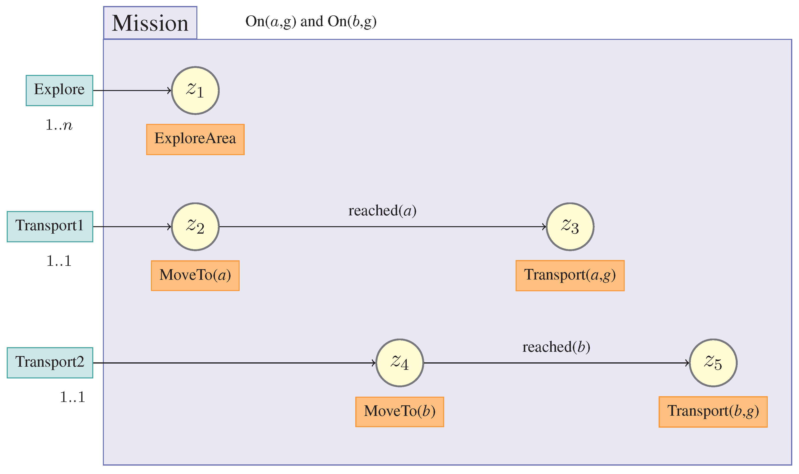
Figure 3 illustrates an example ALICA plan using the core elements of the language for an IMPERA mission. The goal is to achieve the world situation “On(
a,g)” and “On(
b,g)”. The plan shows how to explore the environment till we find the drill samples
a and
b. These samples will be transported to goal position
g. The resulting plan consists of three tasks
(Explore, Transport1 and Transport2). Every agent in the team can be assigned to one of the tasks with respect to the minimum and maximum cardinalities
. The “Mission” plan
contains a state machine for every agent in the team with several states
(yellow circle). Every state contains a plan (orange boxes), which contains a state machine of basic behaviors
. These plans represent the skills of the agents, which will be defined in detail later. The agents can switch states with conditional transitions.
Figure 3.
Example A Language for Interactive Agents (ALICA) plan.
Figure 3.
Example A Language for Interactive Agents (ALICA) plan.
6.2. Constraint Satisfaction Problems
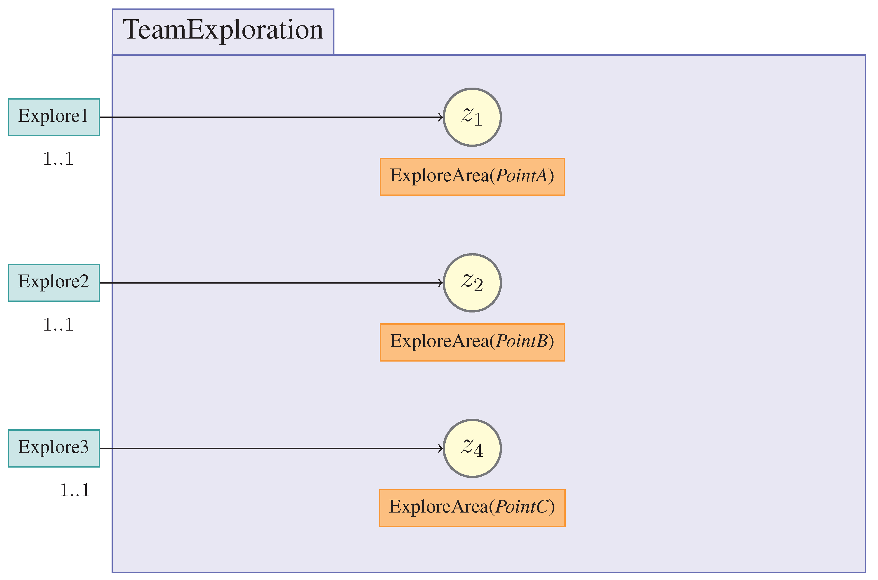
While modeling team activities, we would like to specify high-level behaviors, which are suitable for a random number of agents. However, in many cases, we need a very specific behavior depending on some variables, such as coordinates
,
and
of the behavior in
Figure 4.
Figure 4.
Example modeling problem.
Figure 4.
Example modeling problem.
Finally, we have to define points, where the robots have to drive to. In this case, we have a very specific implementation of the plan “Team Exploration”. Hence, to provide flexibility and modeling convenience, ALICA supports constraint satisfaction problems (CSP) defined by [
3]:
Definition 6.1. A constraint is a formula with free variables , . ϕ is said to constrain . Every is representing a value in a domain . A solution to a constraint formula with respect to a belief base B is a substitution θ, such that is ground, is consistent with B and .
ALICA plans span an acyclic tree; therefore, the constraints have to satisfy recursiveness for all related plans with respect to the belief base B. In our example, the belief base B consists of the facts in the World Modeland predefined predicates.
Consider the following simple example constraints
c:
The constraints state that all goal points in
should maintain a maximal distance to each other (see Equation (
1)), but the agents
should have a minimal distance to these points (see Equation (
2)).
The domain-specific predicates
and
can be expressed as:
Figure 5.
Example plan for constraint satisfaction problems (CSP).
Figure 5.
Example plan for constraint satisfaction problems (CSP).
The resulting plan is now very generic and is suitable for any number of robots.
6.3. Utility Function
ALICA supports a default task assignment using a priority list. Therefore, we have to define an ordered list for how the tasks should be allocated. However, this approach does not work for generating new tasks at runtime. Hence, ALICA uses utility functions to define specific task assignments [
3]. Utility functions will capture the applicability of a plan in a certain situation and determine a task allocation. ALICA imposes a structure on utility functions, which allows one to evaluate these tasks.
A utility function depends on the current situation captured by a domain-specific part, and the current role assignment, captured by a domain-independent function.
Definition 6.2. The function
determines the preferences of all acting agents in task
τ, and plan
p:
where
.
The function represents the sum of all preferences of all agents which are allocated in their corresponding task. This result will be normalised by the factor . Negative preferences express an inability to do something.
Definition 6.3 (Utility Function). The utility
of a plan
p and the belief base
is defined by:
A utility function is a weighted sum of several functions
over belief sets. The weights
are constants defined by
and
. The functions
represent domain-specific information.
6.4. Skills
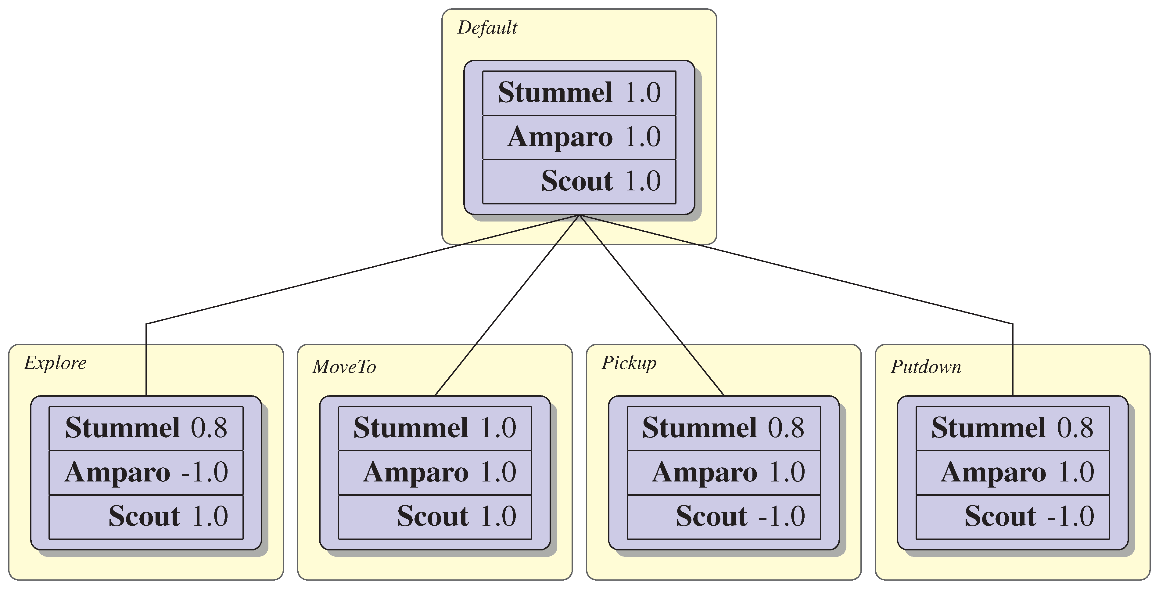
This section describes all skills used in IMPERA. At first, we define the role-task priorities as shown in
Figure 6 that are needed by ALICA. In our mission scenario, we have three different types of roles based on our three different robots. The top-level task is named “Default”. Every robot has the same priority to enter in this task. All robots can move to new tasks, as shown by the edges. However, the tasks “Explore”, “MoveTo”, “Pickup” and “Putdown” have different priorities towards the roles. Amparo is not allowed to explore, because it is too heavy. Scout is the quickest robot; hence, it has the highest priority for “Explore”. We are allowed to send all robots to a certain position defined in the role-task priority “MoveTo”. Scout is not able to “Pickup” and “Putdown”. Furthermore, Amparo has a higher priority to manipulate objects, because its 3D-perception is more precise.
Figure 6.
IMPERA role-task priorities.
Figure 6.
IMPERA role-task priorities.
6.4.1. Multirobot Exploration
At the beginning of our mission scenario, the robots have to explore an unknown environment. One popular approach is to use an occupancy grid map representation, which is explored using frontier cells [
13]. Unknown cells are searched in the local neighborhood of known cells. The map is constructed by the distance scan of the Hokuyo Laserscanner. Algorithm 1 describes how the robots evaluate frontier cells [
14].
![Robotics 04 00435 i001]()
The algorithm starts by using a wave front propagation for every frontier cell f. For every propagation, we remember all traveled cells, observed frontier cells and cells near the map boundary. Condition wave front propagationis true if unexplored cells exist. The information gain of the frontier cells depends on the traveled while a robot discovers a frontier cell f. The cells that are close to the map border will be marked. Afterwards, the algorithm removes observed cells from the frontier cell list. Finally, the algorithm returns a sorted list of frontier cells regarding the information gain charged with boundary relations.
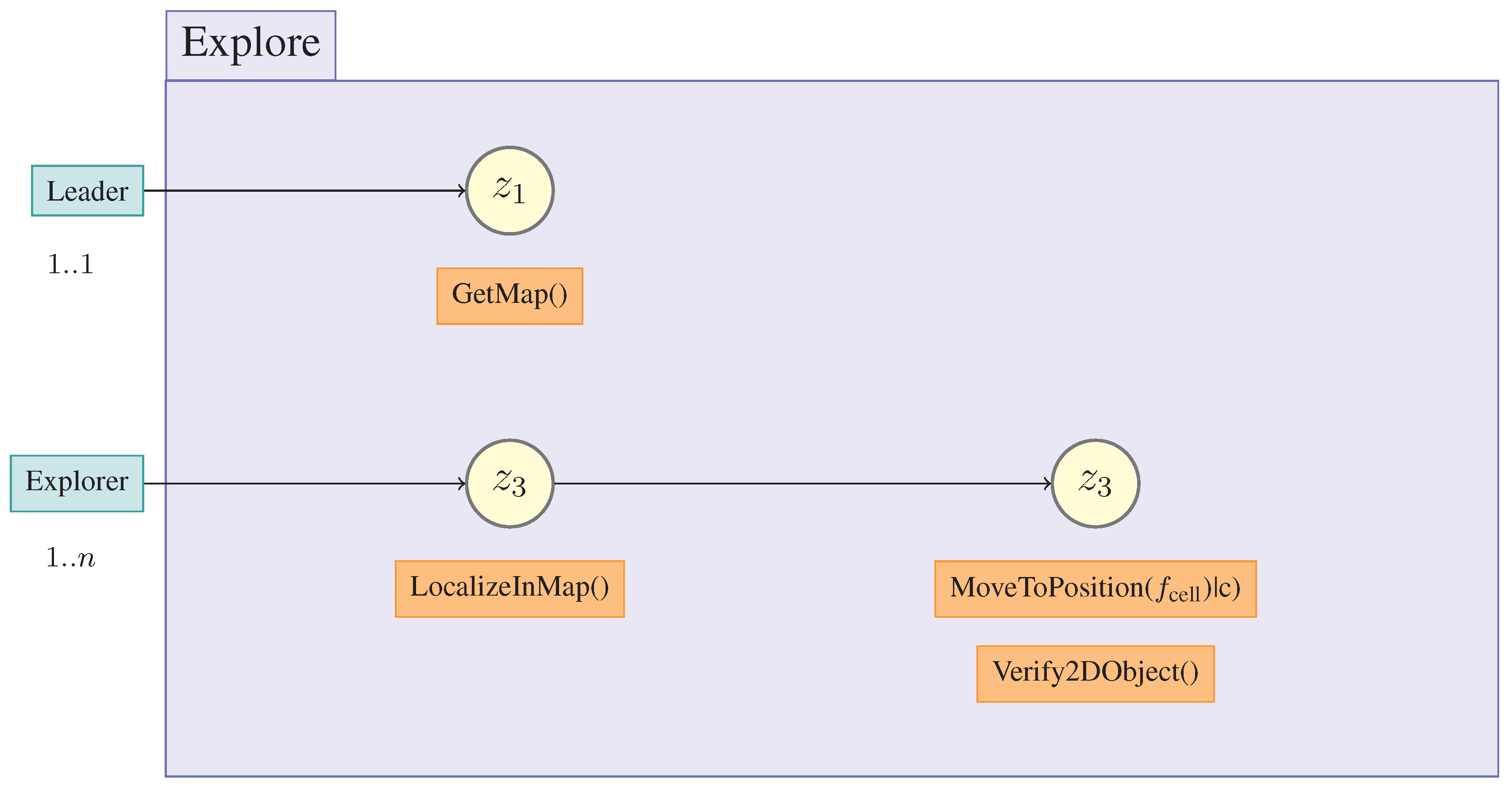
Based on the sorted frontier cells, we start to define the ALICA skill “Explore” shown in
Figure 7. The plan has two tasks. Initially, the team has no map. Hence, one robot starts to create the first map with “GetMap”. After this task is done, all robots localize themselves in this map and start to explore the environment using the frontier cells.
Figure 7.
Exploration skill model in an ALICA plan.
Figure 7.
Exploration skill model in an ALICA plan.
The constraint
c is to coordinate the frontier cell selection:
The goal of the constraint
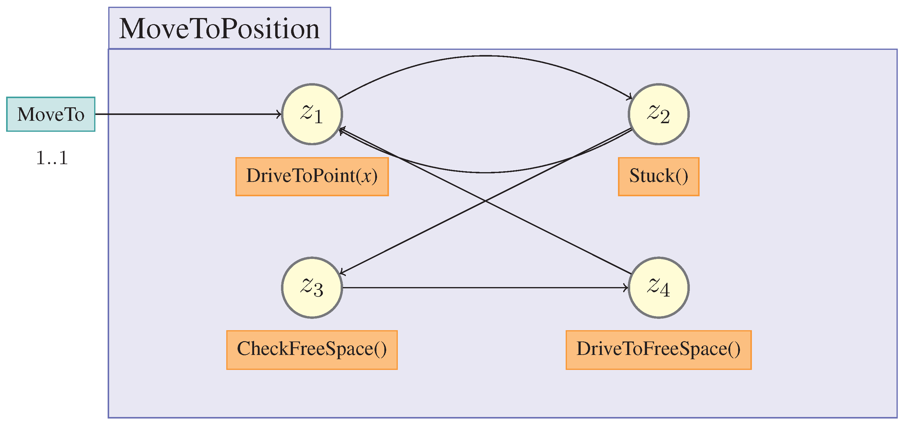
c is to find for every robot the minimal distance to travel, but the distance of the frontier cells should be maximal. Further, the robot will check the environment for drill samples while driving. This plan will be described later. However, for the skill “Explore”, we need a basic navigation skill. This is realized with the plan “MoveToPosition” shown in
Figure 8. The robot should drive to a goal point. If the robot gets stuck in a corner, it will drive into free space.
Figure 8.
Realization of the MoveToPosition skill.
Figure 8.
Realization of the MoveToPosition skill.
6.4.2. Sample Container Detection Using Semantic Perception
The perception of the drill sample has to be robust in the face of noisy sensor data. Based on the perceived information, the robot should be able to grasp the drill sample containers. The identification of the drill sample is solved by a combination of feature extraction and spatial reasoning [
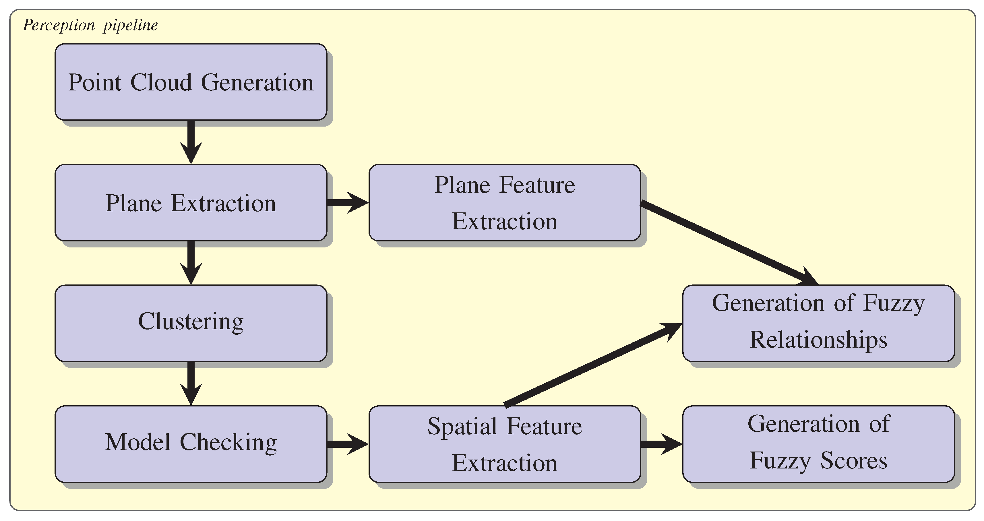
15]. The perception pipeline is shown in
Figure 9. Amparo creates a 3D point cloud using the stereo vision system. The ground plane extraction from the point cloud is solved by a RanSaC (random sample consensus)-based segmentation approach, as described by Schnabel
et al. [
16]. After the ground plane extraction, the rest of the point cloud will be clustered. Points with a minimal distance are added into one cluster. Every cluster is checked if a drill sample model fits. In the next step, the features of the drill sample and of the plane are passed to the FuzzyDL[
17]. Beforehand, the FuzzyDL gets a fuzzy description of the drill sample properties, like radius, height and orientation. Based on this description, FuzzyDL gives an estimate for drill candidates. The key feature of this approach is that we can describe random objects using basic geometries combined with rough semantic relations. Hence, we can easily add new objects.
Figure 9.
Perception pipeline.
Figure 9.
Perception pipeline.
The corresponding plan is shown in
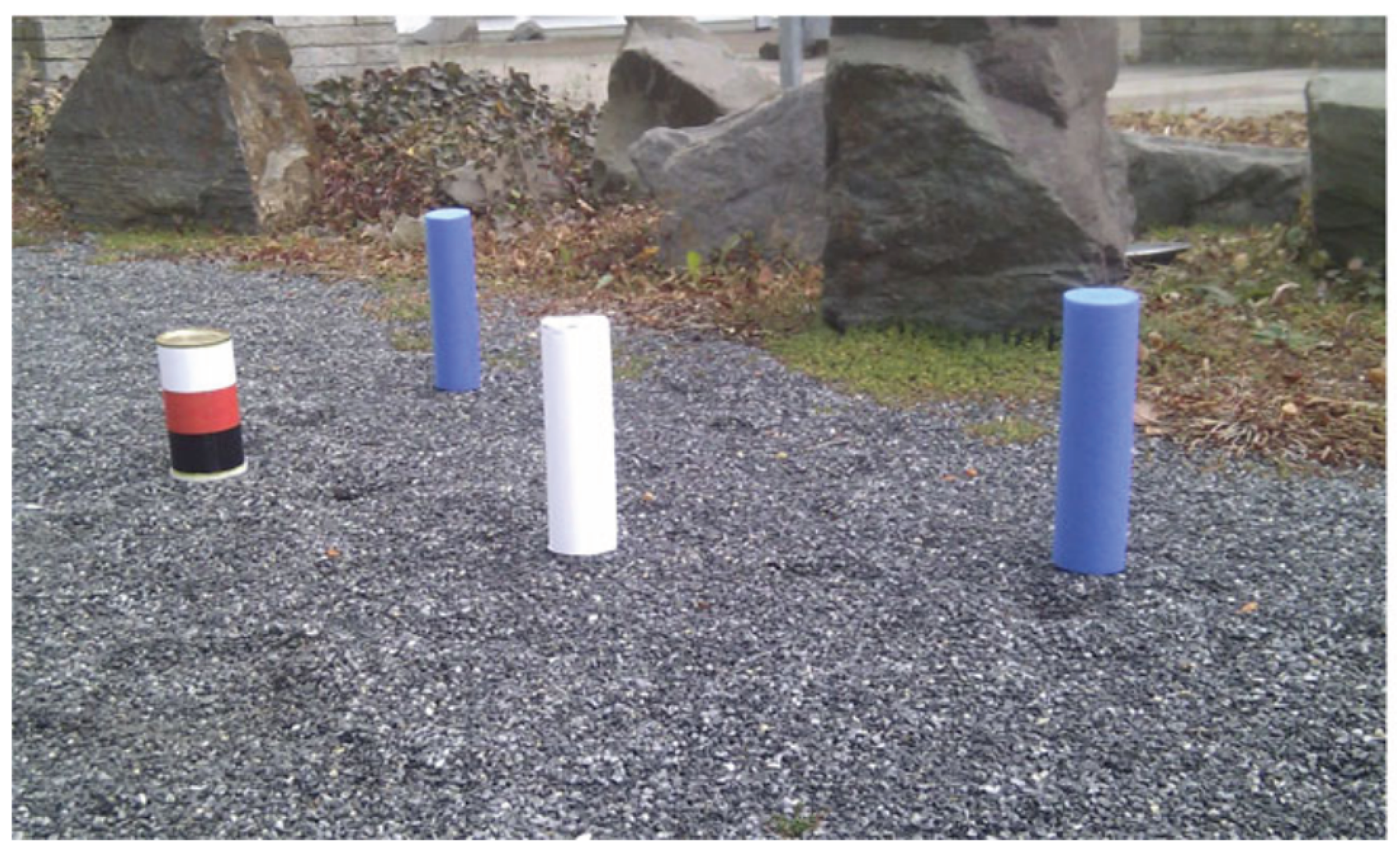
Figure 10 and calls the previously-described perception pipeline. An example of different drill samples that can be distinguished is shown in
Figure 11.
Figure 10.
Semantic perception plan.
Figure 10.
Semantic perception plan.
Figure 11.
Different drill samples.
Figure 11.
Different drill samples.
6.4.3. Sample Container Detection Using Directed Vision
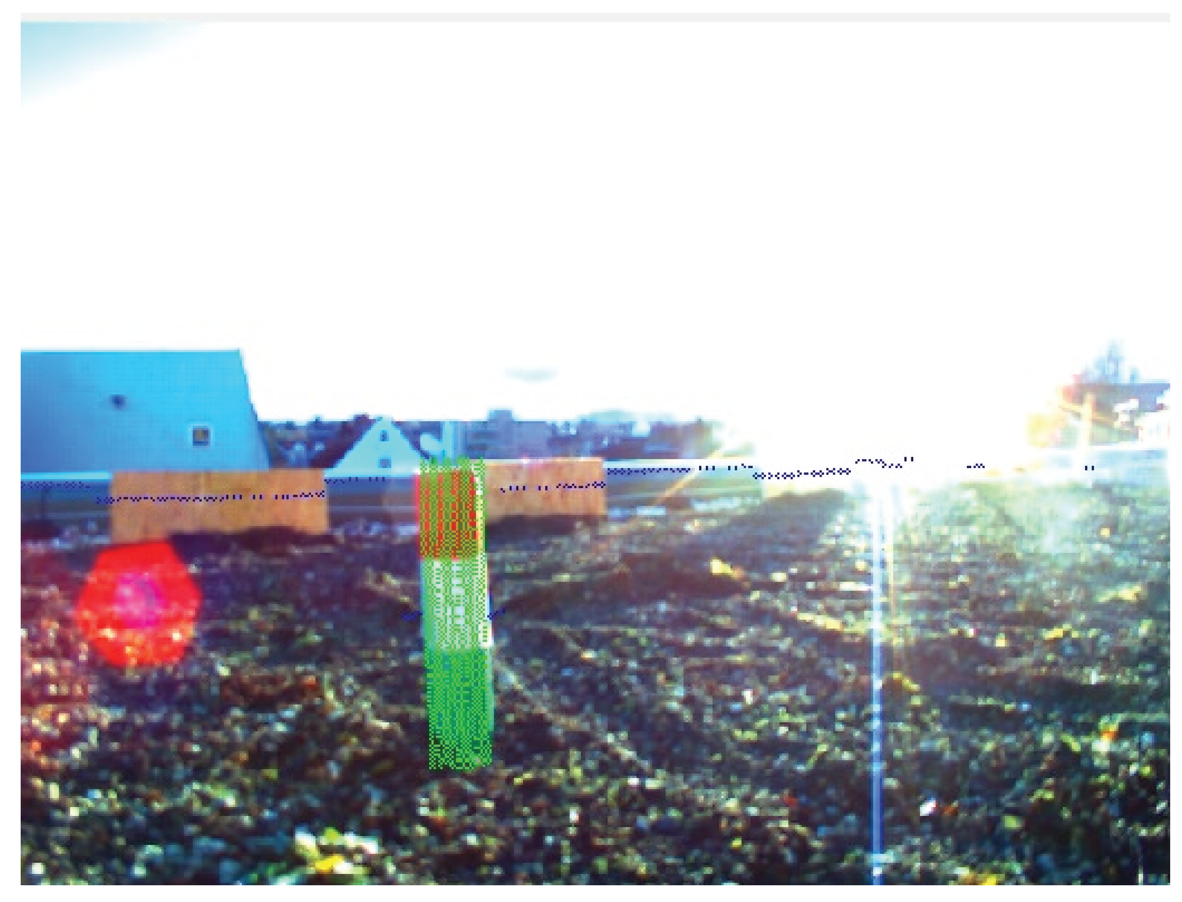
Stummel and Scout have a directed camera. Both robots are able to verify drill samples. Normally, the robots should perform a drill, pick it up and take it back to the base station. We simplify the skill by only detecting the drill samples. We assume the drilling has already been done. Based on the distance scan, taken by the Hokuyo Laserscanner, we search a circular shape with the radius of our predefined drill samples. The laser scanner is able to detect circular-shaped objects for longer distances. Furthermore, we crop the position of the drill sample candidate in the image. For the candidate image, we perform a blob detection [
18] and search for a defined green and red color. The blob detection is done to verify the object and works only for shorter distances. The different predefined samples are encoded by the upper, middle and lower section of the drill samples. The upper and lower sections of the sample can be green or red. The middle section can be black or white. Hence, we are able to encode six different samples. An example image is shown in
Figure 12. In the example, we can see one drill sample with the overlaid area.
Figure 12.
Different drill samples.
Figure 12.
Different drill samples.
The corresponding ALICA plan is shown in
Figure 13.
Figure 13.
Realization of the plan Verify2DObject.
Figure 13.
Realization of the plan Verify2DObject.
6.4.4. Manipulation
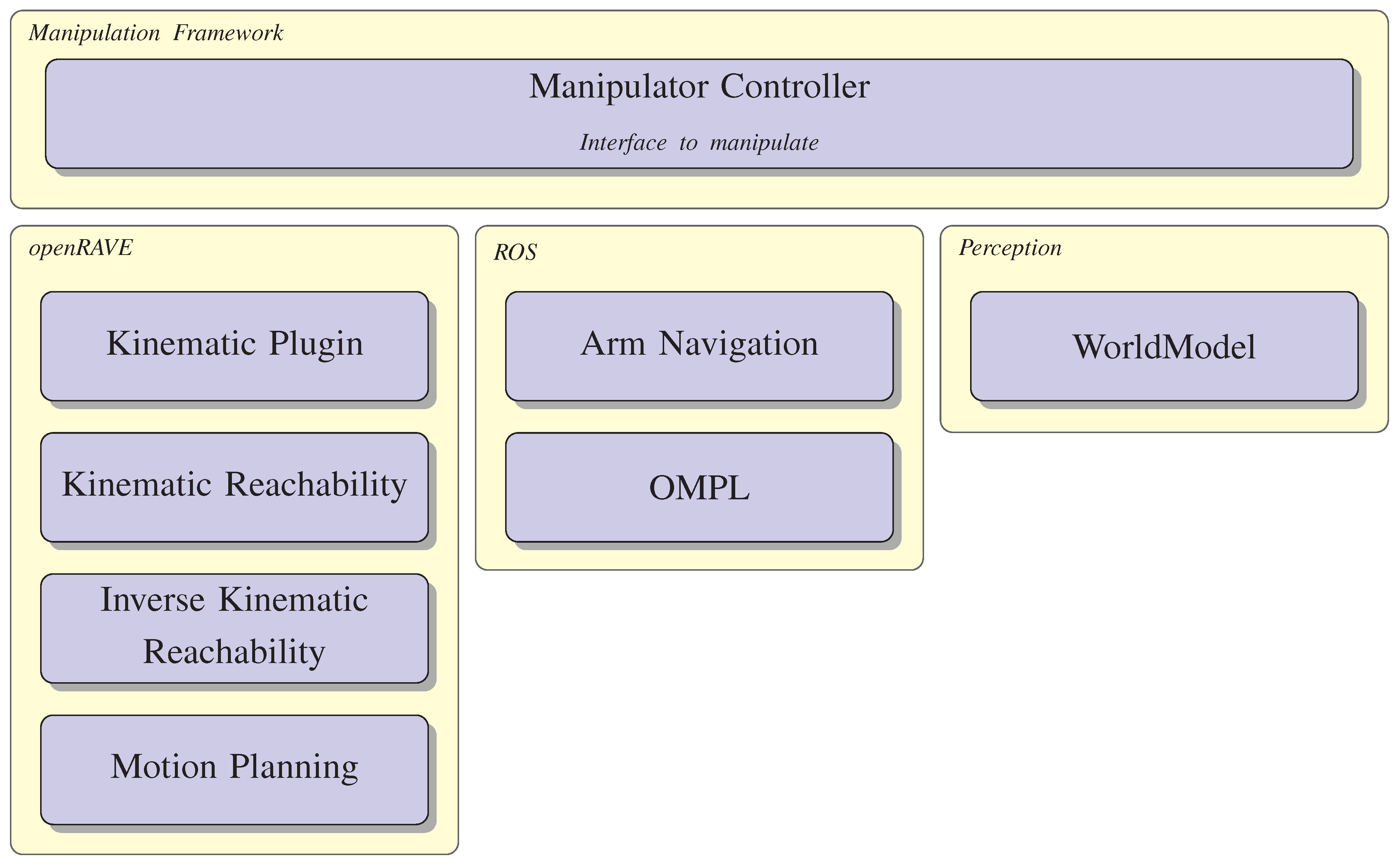
The manipulation task can be done by Stummel and Amparo. For this, both robots are equipped with a Jaco arm. The manipulation framework is shown in
Figure 14. Basically, ALICA can access the arm via the manipulation controller. This controller contains three packages. openRAVE is used to verify the motion planning based on the robot model description. This package will check if the arm has collisions with any joints for forward and inverse kinematics. The execution of the manipulation process is done by the ROS packages Arm Navigation and OMPL (Open Motion Planning). Furthermore, the manipulation controller has access to the WorldModel. If the sensor data change during the execution, the controller is able to react to the environment changes.
Figure 14.
Manipulation framework.
Figure 14.
Manipulation framework.
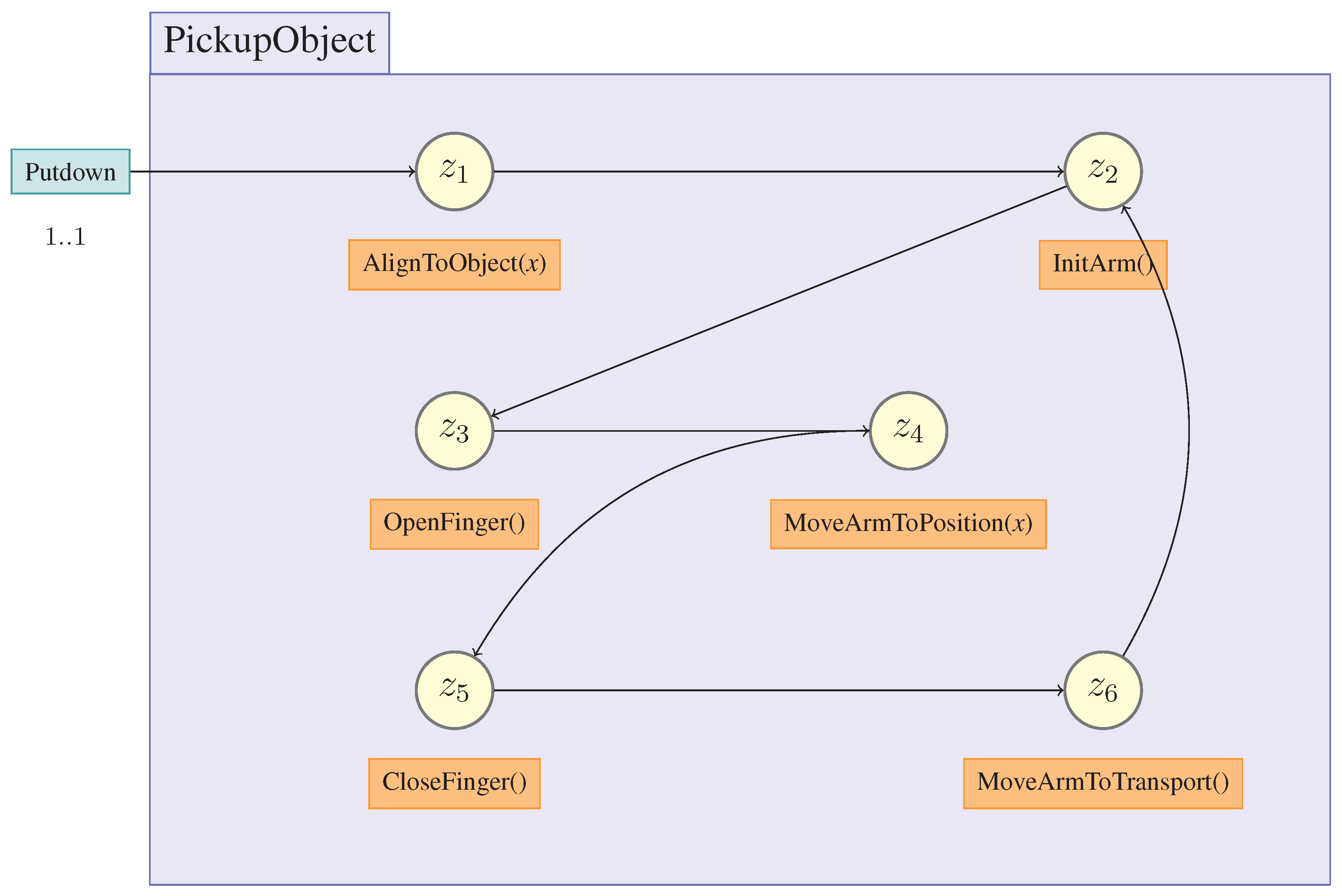
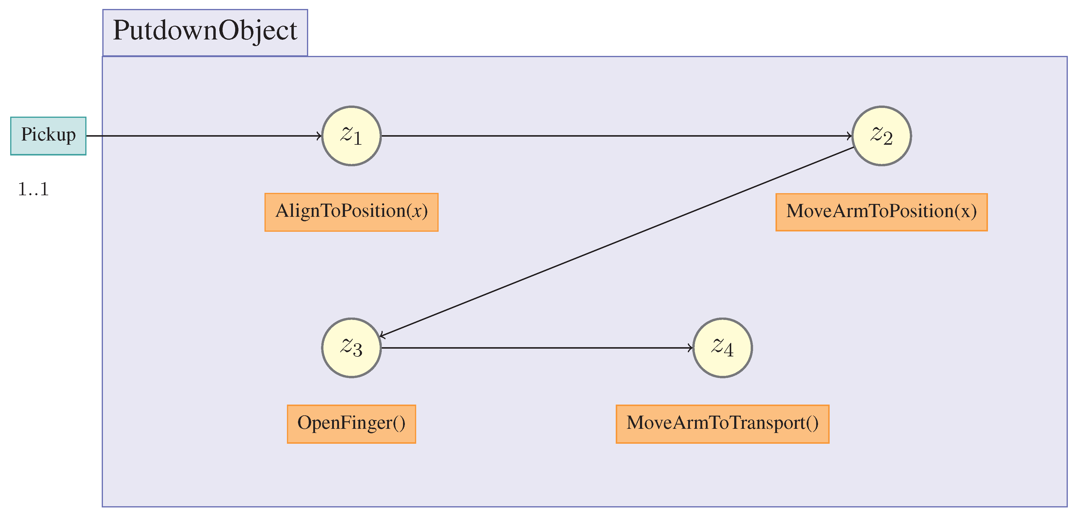
The skills “Pickup” and “Putdown” are shown in
Figure 15 and
Figure 16. Before we pickup an object, we have to align precisely with the object. Afterwards, we are able to grasp the object. After finishing MoveArmToTransport, we validate the force of the fingers. If grasping fails, we will retry the procedure. In the IMPERA scenario, it is assumed that no sample will be inaccessible because of surrounding obstacles.
Figure 15.
Realization of the Pickup skill.
Figure 15.
Realization of the Pickup skill.
Figure 16.
Realization of the Putdown skill.
Figure 16.
Realization of the Putdown skill.
7. Planning
7.1. ALICA Expansions
The language ALICA supports the description of multi-agent plans that can be executed by a team of cooperative robots. This requires that the joint plan has to model every imaginable world state or, otherwise, the team cannot act in unanticipated situations that may happen in our IMPERA mission scenario. Hence, ALICA requires expansions for integrating a planner.
A ProblemElement defines a set of plans . These plans represent our basic skills. The UpdateTimerepresents the soft real time boundary for the planner. pRoPhEt MAS, at a frequency of the UpdateTime, will check if there exists already some possible skills and may update the actual plan. This feature realizes an anytime planning because the planner will offer an intermediate plan by evaluating the heuristic of the search space. Until the first intermediate plan is available, the team executes the WaitPlan. This can be used for positioning or setup for the planning problem. If the planner fails, the team will execute the AlternativePlan as a fallback plan. Finally, the planning problem contains a world and goal description. Furthermore, ALICA uses conditions that were manually coded beforehand. The world situation “World” will update automatically at runtime considering the world model information. However, “World” can be defined specifically to solve planning problems in offline mode or can be set interactively.
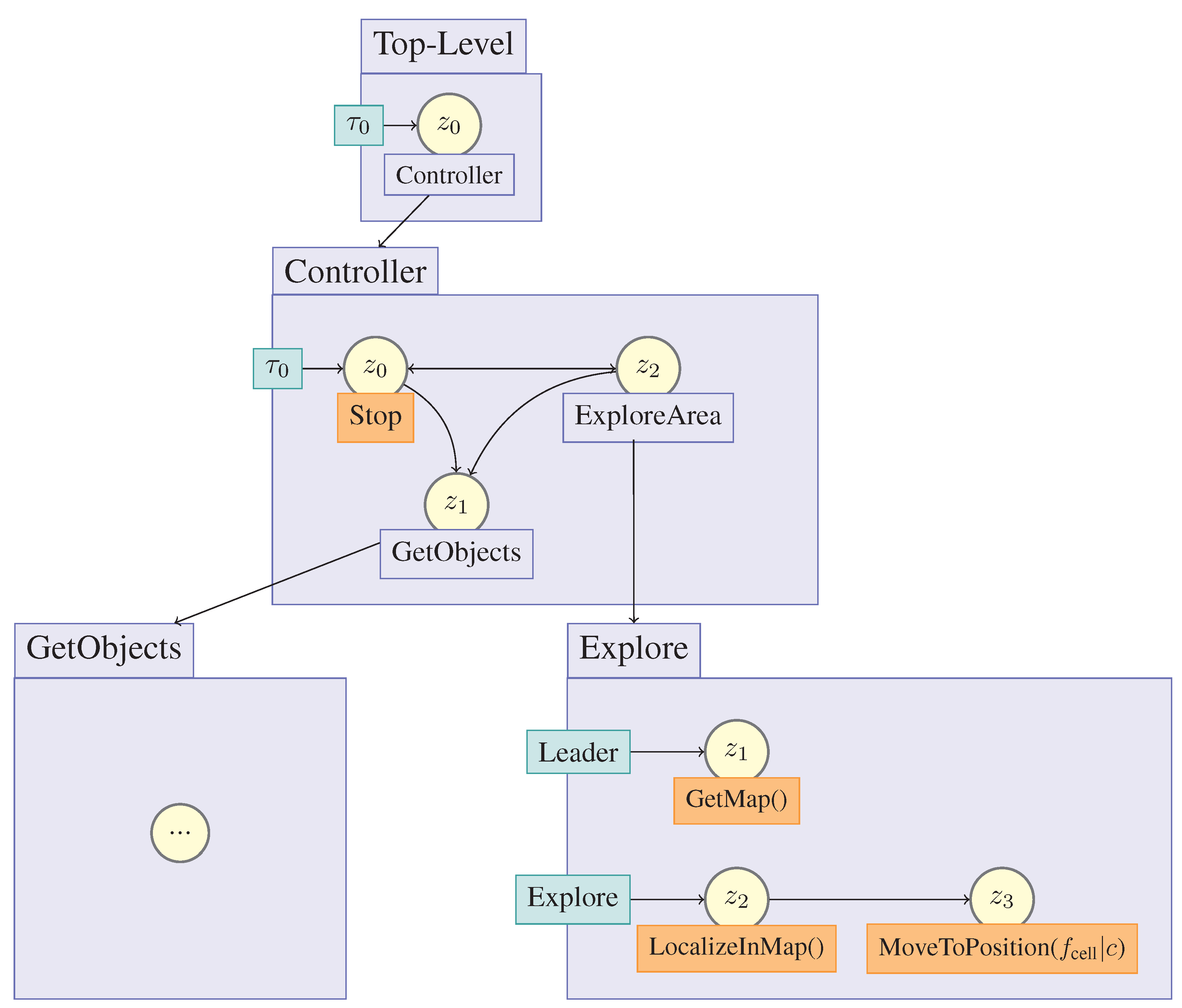
Let us explain how to use planning problems
.
Figure 17 shows an example problem for IMPERA. At the beginning, it is possible to start and stop the team’s behavior. This plan illustrates that the team of agents has to explore an unknown environment. We explicitly model a plan to solve this problem. The problem “GetObjects” is defined as the planning problem, which may contain basic skills like “MoveToObject”, “Pickup” and “Putdown”; therefore, the engine tries to find a plan at runtime. pRoPhEt MAS (Reactive Planning Engine for Multi-Agent Systems) updates the plans depending on the “UpdateTime”. The integrated planning engine searches a valid sequence of skills of the “ProblemElement”, which satisfies the goal. Every root plan must span an acyclic “plan tree” like in
Figure 17. In every situation, we can define a planning problem instead of a static plan.
Figure 17.
Example plan for IMPERA.
Figure 17.
Example plan for IMPERA.
7.2. Planning Engine
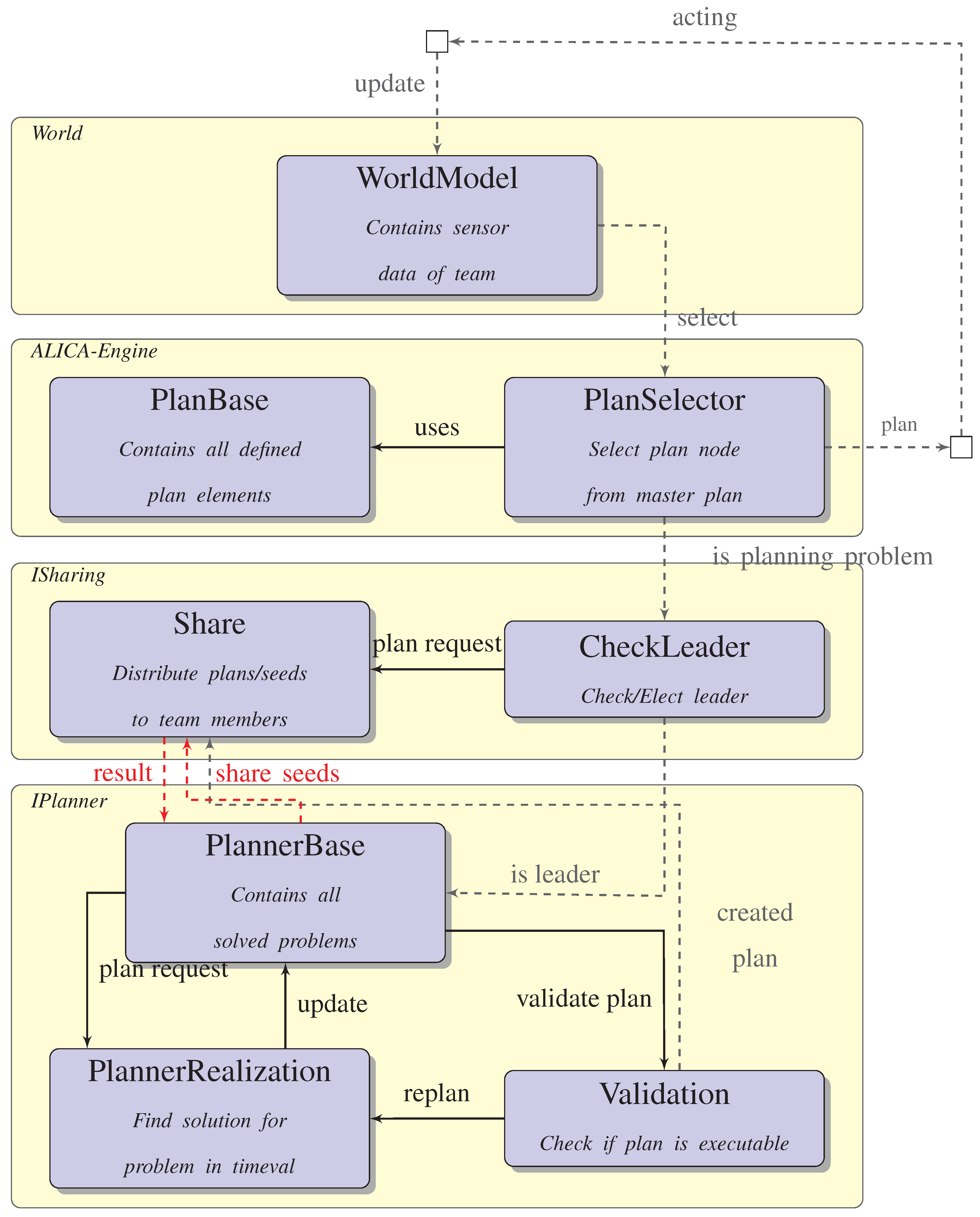
The planning framework pRoPhEt MAS [
4] is shown in
Figure 18.
World and
ALICA Engine are the basic components of the framework. The
WorldModel contains the information about the robots’ environment. In addition, pRoPhEt MAS represents this information in first-order logic. ALICA selects a suitable plan from the
PlanBase, which is modeled by the developer. The ALICA-Engine reacts to environment changes and actively selects new plans. If a planning problem
is defined, the engine will use a planning system for creating a suitable plan. The plan generation is handled by a central leader to reduce the amount of communication. The leader is elected by the team implicitly, while sharing team information periodically via the
ISharing component. Currently, the robot with the lowest ID becomes the leader. The leader starts the computation to solve the planning problem considering
WorldModel. If the leader gets the first results from the planning system, it will share them with its team members after the plan has been validated by the
Validation component. If the team receives new plan updates, the task allocation may need to change. However, ALICA is able to handle switching tasks by its dynamic task allocation. pRoPhEt MAS observes the execution process. If the steps of the planning system do not fulfill the goal, the plan will fail. Every robot will move to the
WaitPlan. Finally, the leader restarts the planning process.
Figure 18.
Planning framework consisting of ALICA for describing team activities expanded by a planning engine.
Figure 18.
Planning framework consisting of ALICA for describing team activities expanded by a planning engine.
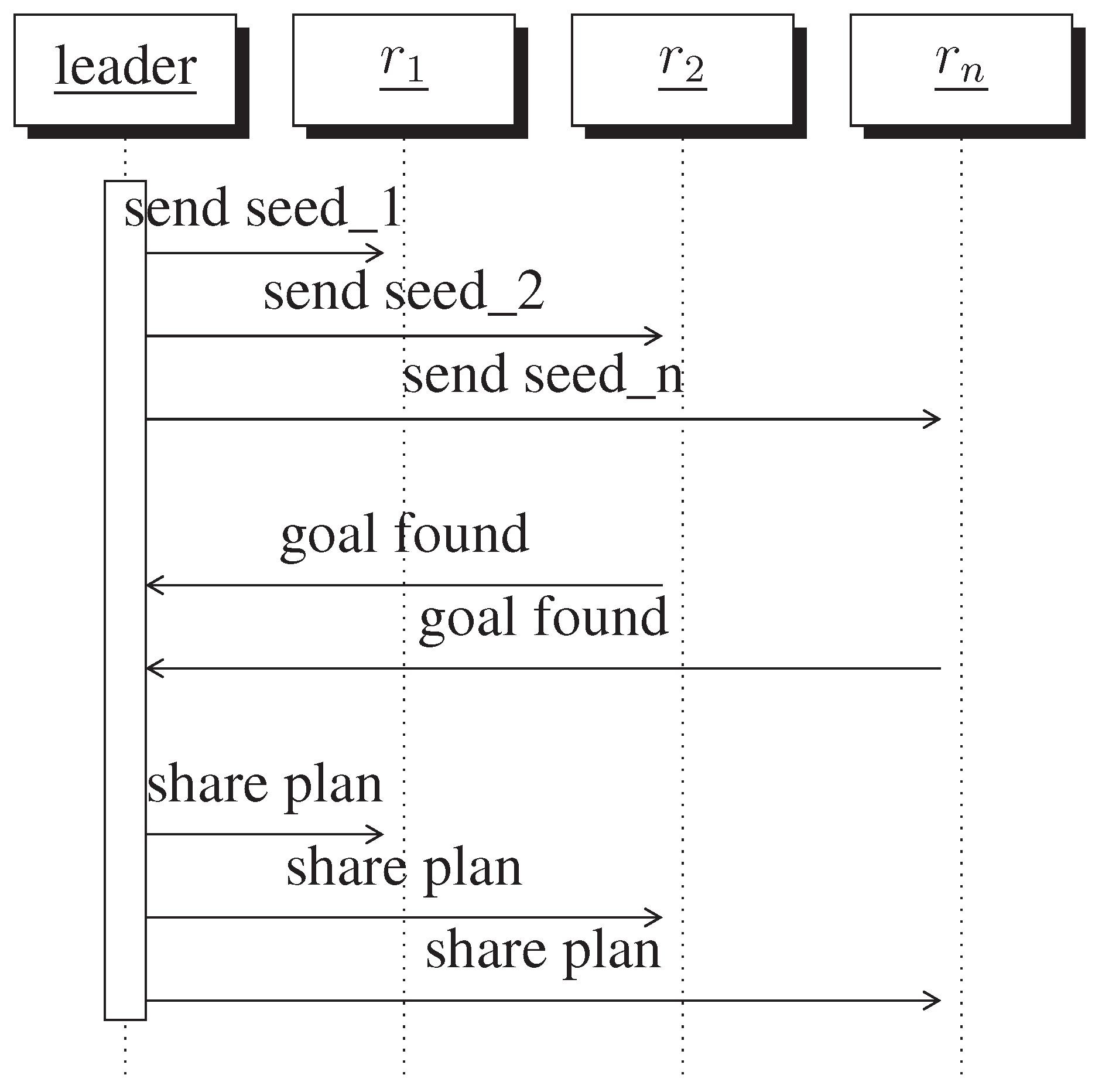
In order to decrease the search time and save memory for the planning process, the leader is able to distribute seeds of the search space to teammates using the “PlannerBase”. If an agent receives a seed, it will start the search and send the solution back to the leader. If the leader receives the first result, he will share this solution with all other members, which will stop the search. The underlying engine to optimize the search is named MAGiC (multi-agent planning using grid computing concepts) [
19]. The strategy for how the leader shares the seeds can be defined by using the
WorldModel. For example, if a robot has low battery capacity, it can be excluded from the parallel planning process. Besides, ALICA sends periodically team messages to observe which robot is reachable. If a robot is no longer reachable, MAGiC will redistribute the seed.
The architecture of pRoPhEt MAS is highly modular. It is possible for
IPlanner to integrate every PDDL-based planner [
20]. Furthermore, it is possible to define planning problems in every desired state, so we can choose a specific planning system suitable for the specific planning problem.
7.3. Task Creation
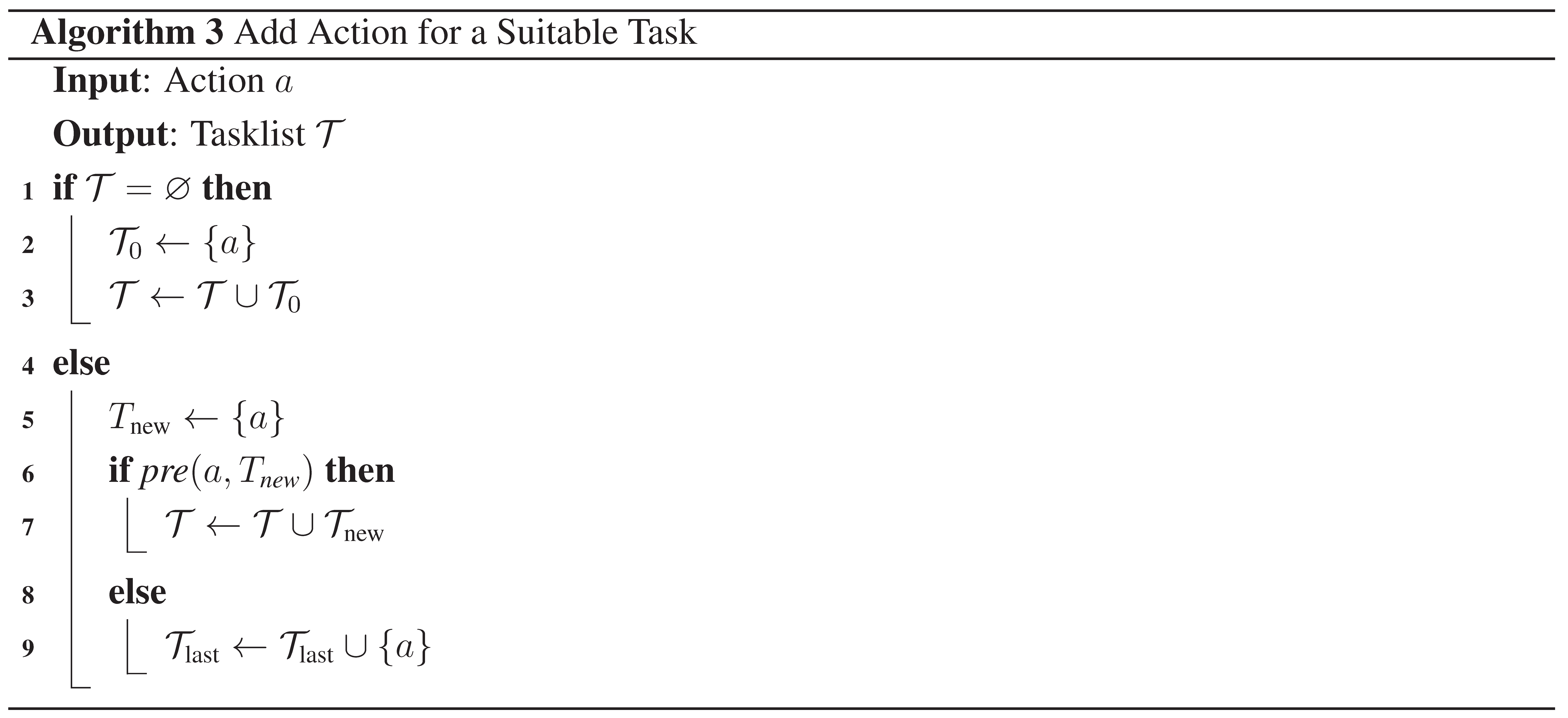
pRoPhEt MAS will create single agent plans. Thus, the search spaceof the problem will be reduced enormously. We divide the problem into two subproblems, i.e., search a single agent plan and find a parallelization of this single agent plan. The algorithm for parallelizing the actions is shown in Algorithms 2 and 3. The algorithm tries to add every action a to a new task, if the precondition (pre) of the action a in a new task holds, which the team has to execute. If an action cannot be executed in a new task , it relies on the task before . Therefore, the algorithm adds this action to the last task.
If pRoPhEt MAS has determined all tasks, we have to define the role-task mapping for the new tasks. It is important to execute these tasks sequentially for the worst case, if the team consists of only one robot. Hence, we define the following role-task mapping.
We prioritize the task from . However, we have to integrate the role priority of the planning problem entry point. Thus, will be normalized for every role with . Finally, pRoPhEt MAS has to set the correct cardinalities for each task. We concatenate different skills with different cardinalities. The minimal cardinalities can be guaranteed if we set the minimum cardinality to . The maximum cardinalities can be guaranteed if we set the maximum cardinality to .
7.4. Utility Function
The generic task allocation of ALICA is not suitable, because it uses a priority list, and in the IMPERA scenarios, we are not able to define this list beforehand. Hence, we have to define a generic utility function that fits for every generated plan regarding the robot preferences. Based on the utility definition of
Section 6.3, we define three different summands, where
x is the number of agents that found a suitable task and
n defines the total number of tasks.
defines the weight of how many tasks are allocated correctly. It is possible that
agents find a suitable task. Hence, the maximum weight is one. As the second weight, we include the task preferences defined in
Section 6.4. If we find an allocation where all robots find the best fitting task, but no robot is allowed to work regarding the precondition, we will prefer an allocation where at least one robot is able to work regarding
. The same fact holds for the last weight
, which defines a similarity value. The robots can oscillate between tasks if the utility changes slightly.
supports changing only if the utility differs at least by
to prevent oscillating tasks. However, we prefer to allocate tasks based on priorities using
rather than a similar allocation
.
8. Evaluation
In the following section, we evaluate our design for three different scenarios:
The planning problem in project IMPERA, which is quite simple, but offers an appropriate proof of concept.
For more dynamic environments, we evaluate pRoPhEt MAS with another team of robots.
Finally, we evaluate the parallel computation of a planning problem in the rover domain.
8.1. Scenario 1: IMPERA Mission
The goal was to explore an unknown environment. Afterwards, the controller should select which interesting object should be brought back by the team. In
Section 6.4, we presented all necessary skills for this scenario. The formal description of the skills containing the conditions is defined by the following pseudocode:
(:action Explore
 :parameters ()
 :precondition
  (not explored)
 :effect
  (explored)
(:action Pickup
 :parameters (?r ?x)
 :precondition
  (and (onground ?x)
  (handempty(?r)))
 :effect
  (and (and (not (onground ?x))
  (not (handempty(?r))))
  (holding ?r ?x)))
(:action Putdown
 :parameters (?r ?x)
 :precondition
  (holding ?r ?x)
 :effect
  (and (not (holding ?r ?x))
  (and (onground ?x)
  (handempty(?r) ) )))
(:action MoveTo
 :parameters (?r ?x)
 :precondition
  (not (on ?r ?x))
 :effect
  (on ?r ?x))
)
The role-task priorities shown in
Figure 6 in
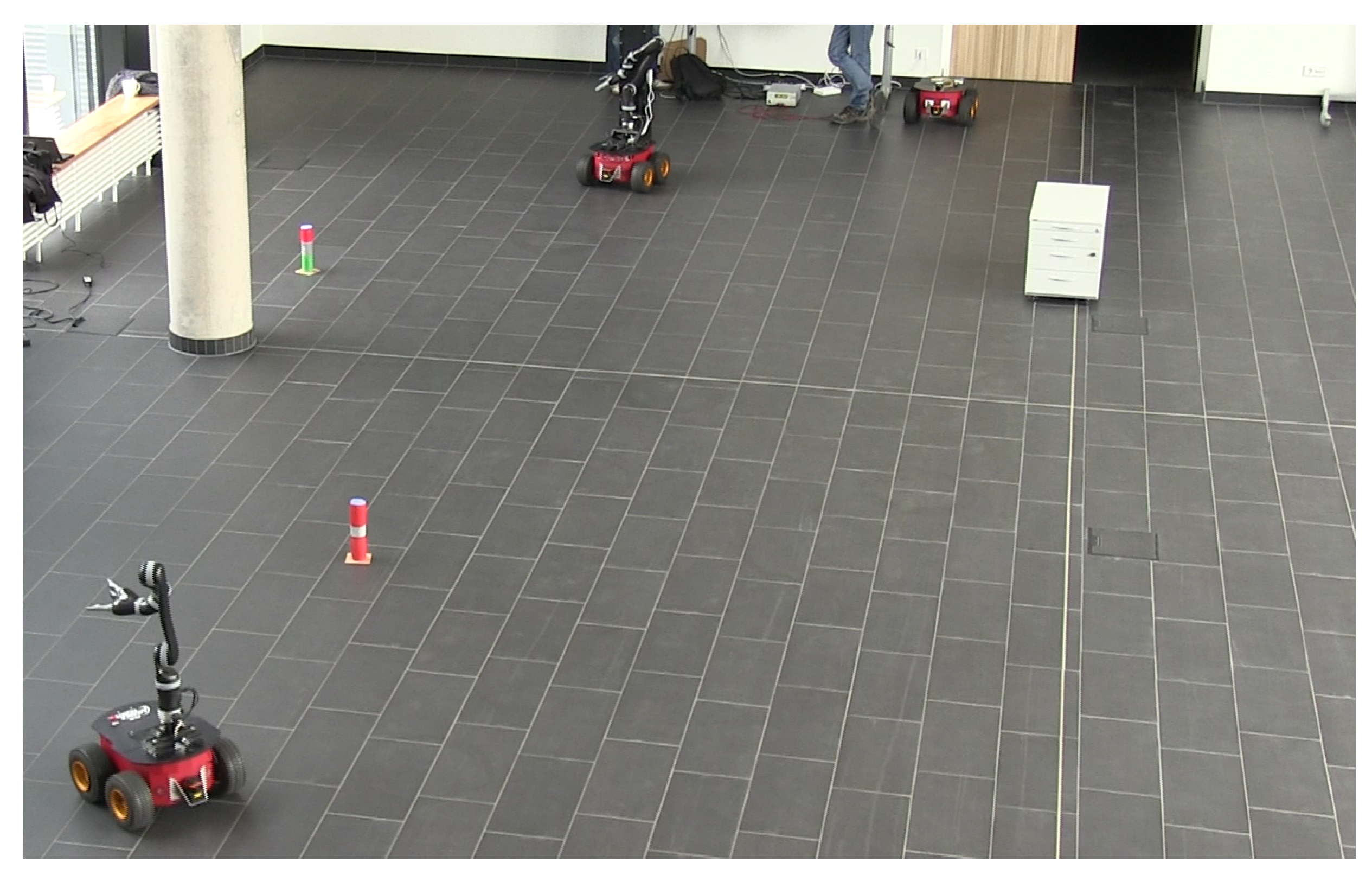
Section 6.4 illustrate that we do not necessarily need all three robots to finalize the mission. Hence, we simulate several robot crashes during the mission. If Scout crashes, ALICA will assign Stummel to explore the environment. If Amparo crashes, Stummel will automatically be assigned to its task, but the plan will fail, if Amparo fails after grasping the object. A snapshot of the final IMPERA demonstration is shown in
Figure 19.
The planning engine pRoPhEt MAS realizes a proof of concept in IMPERA, but cannot be evaluated properly, because the planning problem was too simple. Hence, we evaluate pRoPhEt MAS in further scenarios.
Figure 19.
IMPERA demo scenario.
Figure 19.
IMPERA demo scenario.
8.2. Scenario 2: Dynamic Domain
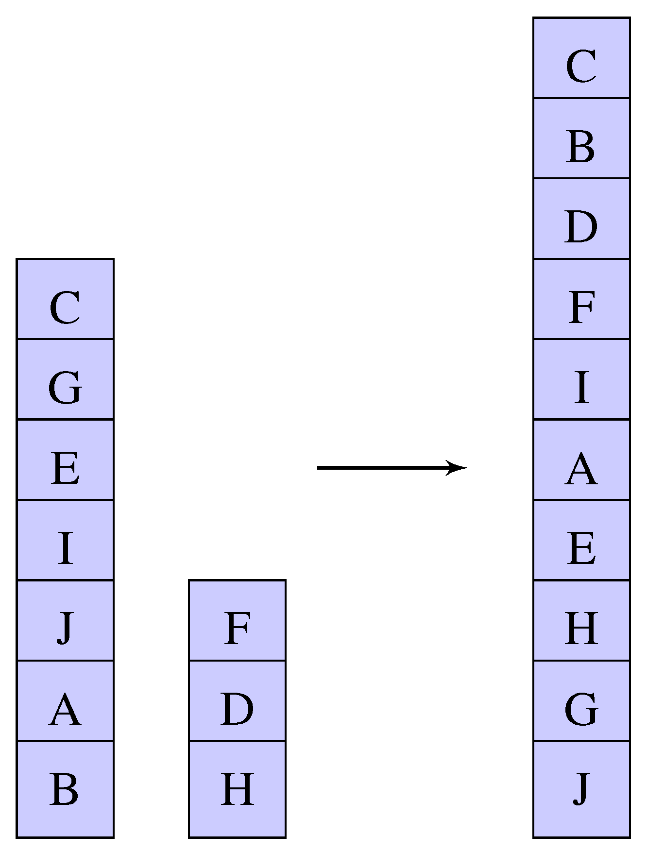
The evaluation focuses on a scenario from the blocks world domain, since the blocks world offers a suitable test bed where the state space increases very quickly. The situation of the scenario is shown in
Figure 20, where the robots can execute four skills, “Pickup”, “Putdown”, “Unstack” and “Stack”. The blocks on the left represent the current situation, which is defined in a planning problem as
World. The blocks on the right represent the situation the team has to reach, which is defined in a planning problem as
Goal. In
WaitPlan, every agent drives to a free position, so as not to disturb other tasks.
AlternativePlan is not defined, so we assume a suitable plan can be found.
Figure 20.
Scenario description.
Figure 20.
Scenario description.
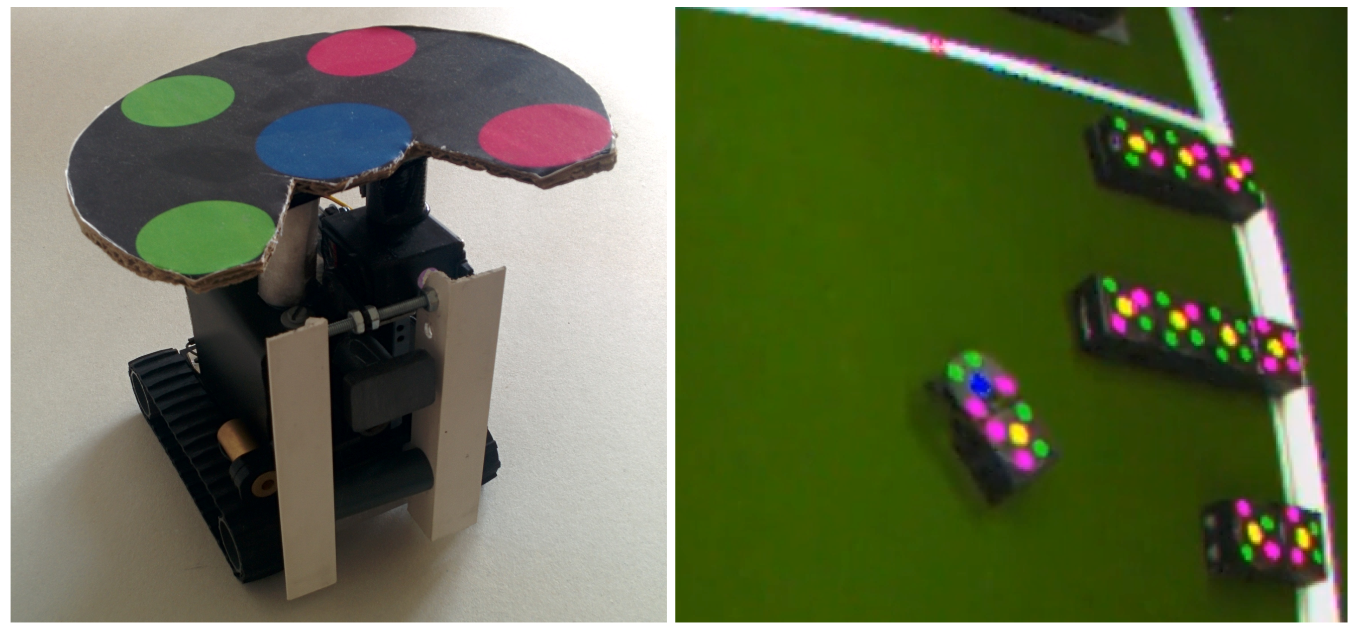
We execute the scenario on real robots. The team consists of up to five Surveyor SRV1 robots (
http://www.surveyor.com). Every robot is equipped with a marker. This marker is used to localize every agent with the localization of the “Robocup Small Size League” [
21]. The localization is a vision-based system and uses one or two overhead cameras to calibrate the markers. In addition, every stack is detected by a marker. To reduce the overhead for grasping, we project the stacks to 2D; if a robot needs to manipulate stacks, it will push the blocks across the ground, as shown in
Figure 21.
Figure 21.
(Left) The Surveyor SRV with marker; (Right) Image from the localization where a robot is pushing a box.
Figure 21.
(Left) The Surveyor SRV with marker; (Right) Image from the localization where a robot is pushing a box.
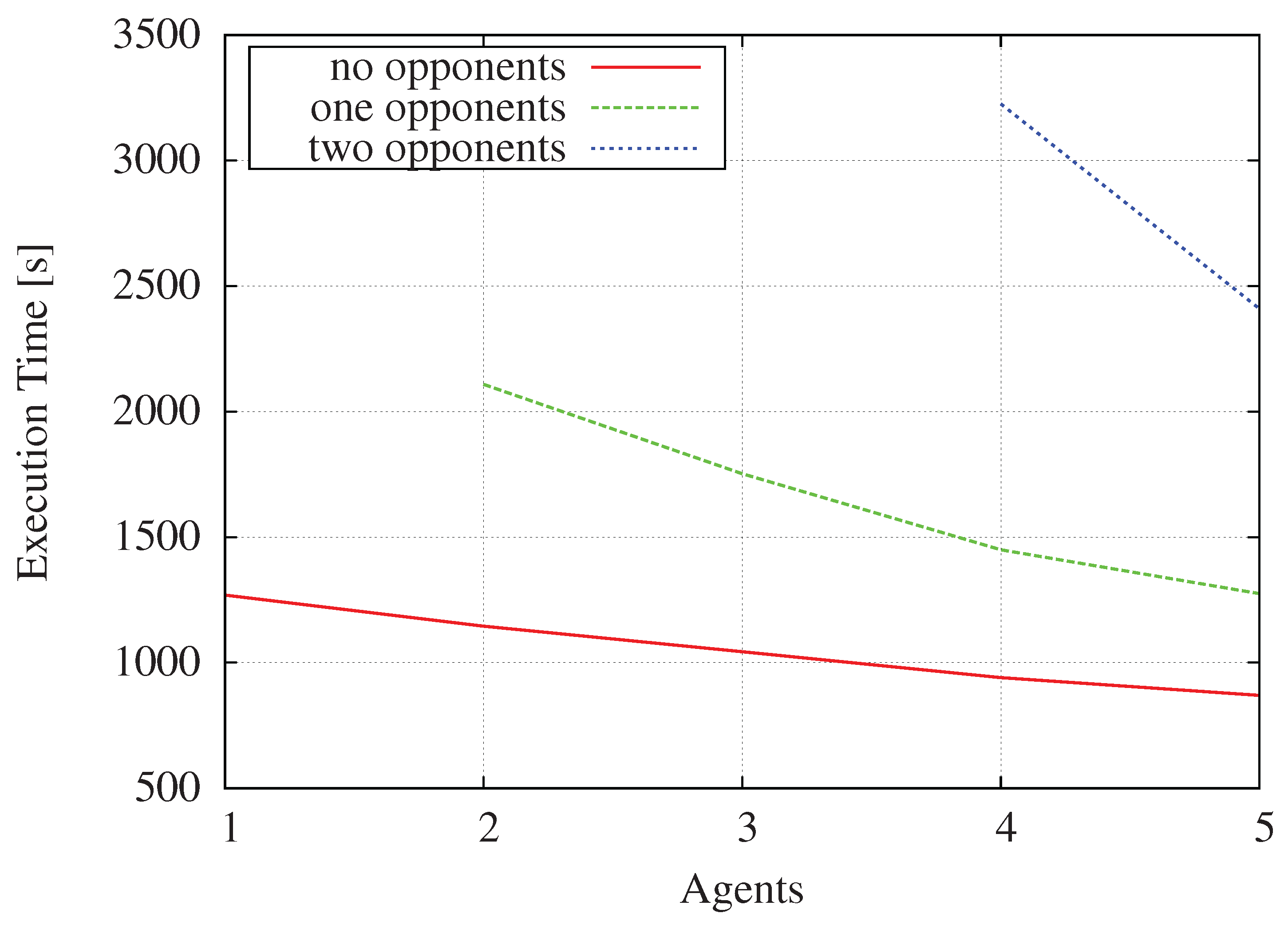
In the first experiment, we use five robots and an
UpdateTime of one second. Next, to realize a dynamic environment, we use different agents as opponents. They are able to select a random skill, if no other robot is blocking this stack at this point. The results are shown in
Figure 22. Without opponents, the total execution time decreases with the number of agents. The robots have to drive slower for a precise position, because of sensor noise. Furthermore, the execution time is higher, since the obstacle avoidance takes more time. With opponents, the time increases, because pRoPhEt MAS has to plan again. However, the selected actions of the opponents are random. Therefore, sometimes, they even help to reach the goal. At the end of the scenario, the opponents often were not able to act, because the stack was blocked by an agent.
Figure 22.
Execution time of the SRV1 surveyor.
Figure 22.
Execution time of the SRV1 surveyor.
8.3. Scenario 3: Parallel Planning Problem
We used NASA’s Mars Rover domain to evaluate MAGiC [
19]. This problem is used as a benchmark for the International Planning Competition (IPC-2002). Rovers have to collect soil and rock samples and bring them back to the lander. This problem is quite similar to the IMPERA domain, where a team of robots has to explore an unknown environment to find objects and carry them back to a certain location.
The evaluation of the IPC problems is shown in
Table 1. For all planning problems, we ran a modified fast downward planner (FDP) [
22], which divides the search space into the number of agents in the team. Moreover, we add the results of multi-agent forward search (MAFS) [
9] into the table. All lines with minus were not evaluated by MAFS. Both use eager best-first search and an alternation open list with one queue for each of the two heuristic functions
ff [
23] and
context-enhanced additive heuristic[
9]. Experiments were run on an Intel i7-2630QM CPU 2.00 GHz processor; the time limit was set to 30 minutes; and memory usage was limited to 4 GB. For all problems, the fast downward planner is
faster than MAFS on average, but MAFS got on average
better resulting costs. The costs represent the quality of the found plan. Every action in a plan generates a unit cost. pRoPhEt MAS divides the seeds over all team members, as shown in
Figure 23.
The leader needs to distribute the problem to all n agents. These agents return the result. Finally, the central agent distributes the final solution. The upper communication bound for n agents is limited to . On average, FDP requires 98.2% fewer messages than MAFS for the evaluated problems “Rovers5” to “Rovers17”.
Overall, the evaluations demonstrate a simple strategy to optimize the planning time using parallel computation, compared to Nissim [
9]. Algorithms for parallel computation similar to Burns
et al. [
10] are able to further improve the planning time. However, to achieve planning with parallel computing, the communication overhead increases substantially. Our focus is to communicate as little as possible to cope with unreliable communications and to save battery capacity.
Table 1.
The table contains an evaluation for NASA’s Mars Rover domain of multi-agent forward search (MAFS) and fast downward planner (FDP). Solution cost (steps), running time (in s) and the number of sent messages are shown.
Table 1.
The table contains an evaluation for NASA’s Mars Rover domain of multi-agent forward search (MAFS) and fast downward planner (FDP). Solution cost (steps), running time (in s) and the number of sent messages are shown.
| Problem | # | Costs | Runtime | Messages |
|---|
| Agents | MAFS | FDP | MAFS | FDP | MAFS | FDP |
|---|
| Rovers1 | 1 | - | 10 | - | 0.046 | - | 0 |
| Rovers2 | 1 | - | 8 | - | 0.037 | - | 0 |
| Rovers3 | 2 | - | 13 | - | 0.05 | - | 3 |
| Rovers4 | 2 | - | 10 | - | 0.054 | - | 3 |
| Rovers5 | 2 | 22 | 22 | 0.13 | 0.069 | 84 | 3 |
| Rovers6 | 2 | 37 | 38 | 0.07 | 0.074 | 27 | 3 |
| Rovers7 | 3 | 18 | 18 | 0.07 | 0.076 | 225 | 6 |
| Rovers8 | 4 | 26 | 28 | 0.2 | 0.143 | 937 | 6 |
| Rovers9 | 4 | 38 | 34 | 0.82 | 0.206 | 380 | 6 |
| Rovers10 | 4 | 38 | 36 | 0.41 | 0.251 | 271 | 6 |
| Rovers11 | 4 | 37 | 38 | 0.34 | 0.382 | 299 | 6 |
| Rovers12 | 4 | 21 | 22 | 0.09 | 0.05 | 435 | 6 |
| Rovers13 | 4 | 49 | 46 | 0.15 | 0.272 | 472 | 6 |
| Rovers14 | 4 | 31 | 32 | 0.42 | 0.208 | 310 | 6 |
| Rovers15 | 4 | 46 | 44 | 0.33 | 0.306 | 252 | 6 |
| Rovers16 | 4 | - | 43 | - | 0.374 | - | 6 |
| Rovers17 | 6 | 52 | 52 | 0.57 | 0.3 | 628 | 15 |
| Rovers18 | 6 | - | 48 | - | 1.36 | - | 15 |
| Rovers19 | 6 | - | 74 | - | 16.099 | - | 15 |
| Rovers20 | 8 | - | 87 | - | 9.673 | - | 21 |
| Rovers21 | 6 | - | 68 | - | 5.887 | - | 15 |
| Rovers22 | 6 | - | 69 | - | 15.93 | - | 15 |
| Rovers23 | 8 | - | 80 | - | 16.493 | - | 21 |
| Rovers24 | 8 | - | 122 | - | 214.782 | - | 21 |
| Rovers25 | 10 | - | 31 | - | 2.418 | - | 27 |
| Rovers26 | 10 | - | 62 | - | 5.682 | - | 27 |
| Rovers27 | 10 | - | 103 | - | 73.524 | - | 27 |
| Rovers28 | 10 | - | 78 | - | 28.361 | - | 27 |
| Rovers29 | 10 | - | 60 | - | 22.616 | - | 27 |
| Rovers30 | 10 | - | 115 | - | 113.091 | - | 27 |
| Rovers31 | 12 | - | 140 | - | 1168.313 | - | 33 |
| Rovers32 | 12 | - | 0 | - | 0 | - | 33 |
Figure 23.
Share seeds to accelerate search.
Figure 23.
Share seeds to accelerate search.
9. Conclusions and Future Work
In our research project IMPERA, we solved a problem similar to the Mars Exploration Rover of NASA. However, our focus is on the coordinated teamwork of autonomous robots. The robot team has to collaboratively explore an unknown lunar environment and collect lunar drill samples.
In this paper, first, we gave an overview of the IMPERA system architecture. ALICA enables one to organize the robots in a completely decentralized way. Then, we described all necessary robot skills for the IMPERA scenario. Key components of our solution are the plan description language ALICA, which is used to define the team behavior, and the planning system pRoPhEt MAS, which extends ALICA to realize a mission planning system. As proof of concept, we evaluated the planning system in three different scenarios. pRoPhEt MAS aims at dynamic multi-robot environments. We have shown that pRoPhEt MAS effectively supports parallel planning in the rover domain.
Our next steps will concentrate on a plan repair mechanism. Currently, we re-plan if the team is no longer able to reach the goal. Obviously, planning and re-planning increases the communication load substantially. Thus, an improvement would be to evaluate and tune the coordination overhead for re-planning, similar to [
24], considering the communication load.
Acknowledgments
The project IMPERA was funded by the German Space Agency (DLR, Grant Number: 50RA1112) with federal funds of the Federal Ministry of Economics and Technology (BMWi) in accordance with the parliamentary resolution of the German Parliament.
Author Contributions
D.S. is the main software developer of the planning engine pRoPhEt MAS. The language ALICA was developed by H.S. Finally, the described skills were implemented by the DFKIBremen during the collaborative research project IMPERA.
Conflicts of Interest
The authors declare no conflicts of interest.
References
- NASA. Mars Exploration Rover. Available online: http://mars.nasa.gov/mer/home (accessed on 30 February 2015).
- NASA. Mars Science Lab. Available online: http://mars.nasa.gov/msl (accessed on 30 February 2015).
- Skubch, H. Modelling and Controlling of Behaviour for Autonomous Mobile Robots; Westdeutscher Verlag GmbH: Wiesbaden, Germany, 2013. [Google Scholar]
- Saur, D.; Geihs, K. pRoPhEt MAS: Reactive Planning Engine for Multi-Agent Systems. In Proceedings of the 13th International Conference on Intelligent Autonomous Systems (IAS), Padova, Italy, 3 September 2015; pp. 147–157.
- Eich, M.; Hartanto, R.; Kasperski, S.; Natarajan, S.; Wollenberg, J. Towards Coordinated Multirobot Missions for Lunar Sample Collection in an Unknown Environment. J. Field Robot. 2014, 31, 35–74. [Google Scholar] [CrossRef]
- Skubch, H.; Wagner, M.; Reichle, R.; Geihs, K. A modeling language for cooperative plans in highly dynamic domains. Mechatronics 2011, 21, 423–433. [Google Scholar] [CrossRef]
- Volpe, R. Rover Functional Autonomy Development for the Mars Mobile Science Laboratory; Jet Propulsion Laboratory: Pasadena, CA, USA, 2003. [Google Scholar]
- Brenner, M.; Nebel, B. Continual planning and acting in dynamic multiagent environments. Auton. Agent Multi Agent Syst. 2009, 19, 297–331. [Google Scholar] [CrossRef]
- Nissim, R.; Brafman, R.I. Distributed Heuristic Forward Search for Multi-Agent Systems. Available online: http://arxiv.org/abs/1306.5858 (accessed on 30 February 2015).
- Burns, E.; Lemons, S.; Ruml, W.; Zhou, R. Best-first heuristic search for multicore machines. J. Artif. Intell. Res. 2010, 39, 689–743. [Google Scholar]
- Gutmann, J.S.; Konolige, K. Incremental mapping of large cyclic environments. In Proceedings of the Computational Intelligence in Robotics and Automation (CIRA), Monterey, CA, USA, 8–9 November 1999; pp. 318–325.
- Pardo-Castellote, G. Omg data-distribution service: Architectural overview. In Proceedings of the 23rd International Conference on IEEE Distributed Computing Systems Workshops, Washington, DC, USA, 19–22 May 2003; pp. 200–206.
- Yamauchi, B. A frontier-based approach for autonomous exploration. In Proceedings of the Computational Intelligence in Robotics and Automation (CIRA), Monterey, CA, USA, 10–11 July 1997; pp. 146–151.
- Kasperski, S.; Wollenberg, J.; Eich, M. Evaluation of cooperative exploration strategies using full system simulation. In Proceedings of the 16th International Conference on Advanced Robotics (ICAR), Montevideo, Uruguay, 25–29 November 2013; pp. 1–6.
- Eich, M.; Dabrowska, M.; Kirchner, F. Semantic labeling: Classification of 3D entities based on spatial feature descriptors. In Proceedings of the IEEE International Conference on Robotics and Automation (ICRA), Anchorage, AK, USA, 3–7 May 2010.
- Schnabel, R.; Wahl, R.; Klein, R. Efficient RANSAC for point-cloud shape detection. Comput. Gr. Forum 2007, 26, 214–226. [Google Scholar] [CrossRef]
- Bobillo, F.; Straccia, U. FuzzyDL: An expressive fuzzy description logic reasoner. In Proceedings of the IEEE International Conference on Fuzzy Systems. FUZZ-IEEE 2008, (IEEE World Congress on Computational Intelligence), Hong Kong, China, 1–6 June 2008; pp. 923–930.
- Danker, A.J.; Rosenfeld, A. Blob detection by relaxation. Pattern Anal. Mach. Intell. IEEE Trans. 1981, 6, 79–92. [Google Scholar] [CrossRef]
- Saur, D.; Haque, T.R.; Herzog, R.; Geihs, K. MAGiC : Multi-Agent Planning Using Grid Computing Concepts. In Proceedings of the 12th International Symposium on Artificial Intelligence, Robotics and Automation in Space-i-SAIRAS, Montreal, QC, Canada, 17–19 June 2014.
- Ghallab, M.; Isi, C.K.; Penberthy, S.; Smith, D.E.; Sun, Y.; Weld, D. PDDL—The Planning Domain Definition Language; Yale Center for Computational Vision and Control: New Haven, CT, USA, 1998. [Google Scholar]
- Zickler, S.; Laue, T.; Birbach, O.; Wongphati, M.; Veloso, M.M. SSL-Vision: The Shared Vision System for the RoboCup Small Size League; Springer: Cham, Switzerland, 2009; Volume 5949, pp. 425–436. [Google Scholar]
- Helmert, M. The fast downward planning system. J. Artif. Intell. Res. 2006, 26, 191–246. [Google Scholar]
- Hoffmann, J.; Nebel, B. The FF planning system: Fast plan generation through heuristic search. J. Artif. Intell. Res. 2001, 14, 253–302. [Google Scholar]
- Skubch, H.; Wagner, M.; Reichle, R.; Triller, S.; Geihs, K. Towards a comprehensive teamwork model for highly dynamic domains. In Proceedings of the 2nd International Conference on Agents and Artificial Intelligence, Valencia, Spain, 22–24 January 2010; pp. 121–127.
© 2015 by the authors; licensee MDPI, Basel, Switzerland. This article is an open access article distributed under the terms and conditions of the Creative Commons Attribution license (http://creativecommons.org/licenses/by/4.0/).


