
IPAnema Safe: A Cable-Driven Parallel Robot for Safe Operation Above People

 , , , , , and
Abstract
1. Introduction
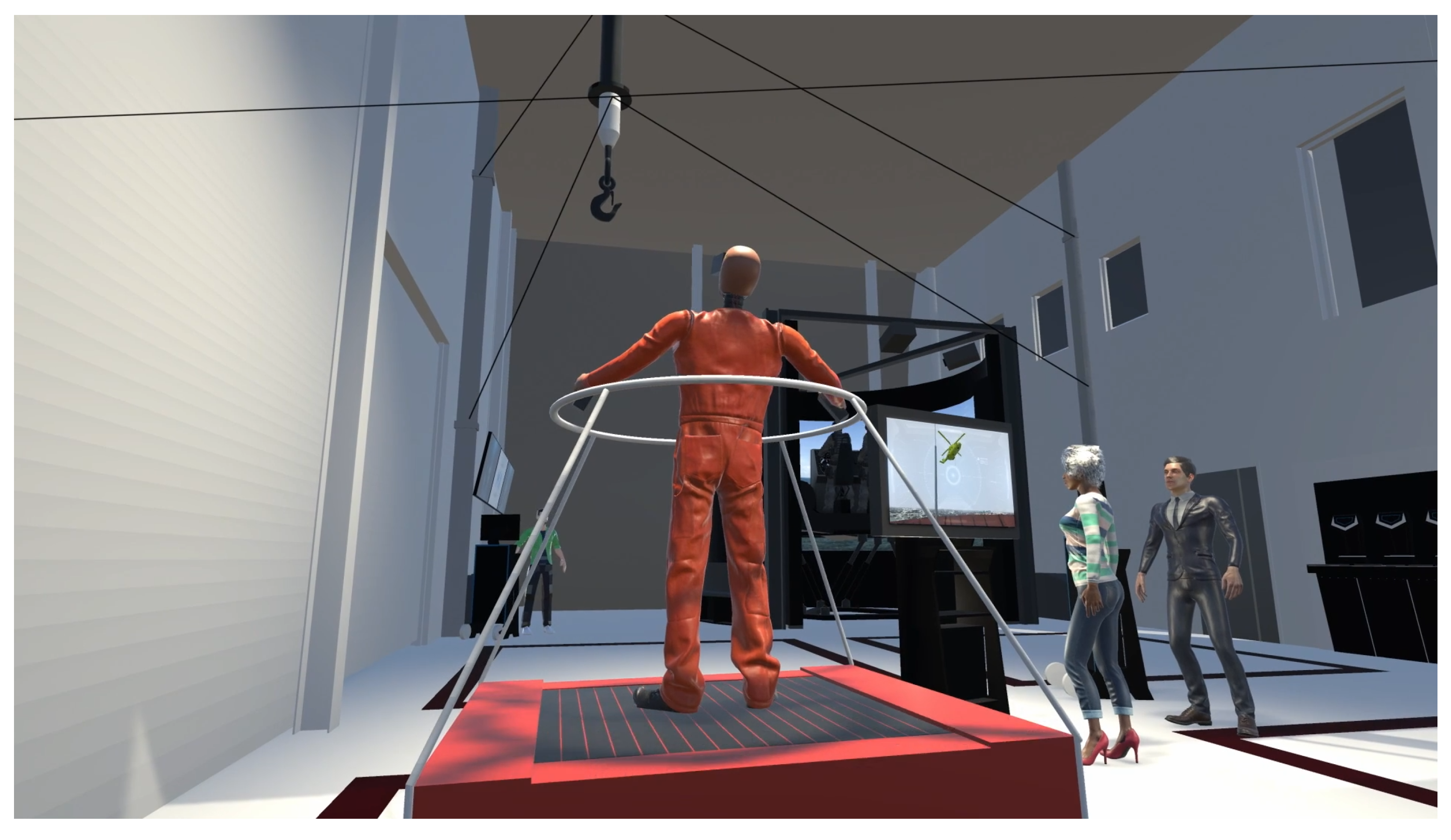
2. Use Case
3. Requirements
3.1. Mechanical and Physical Requirements
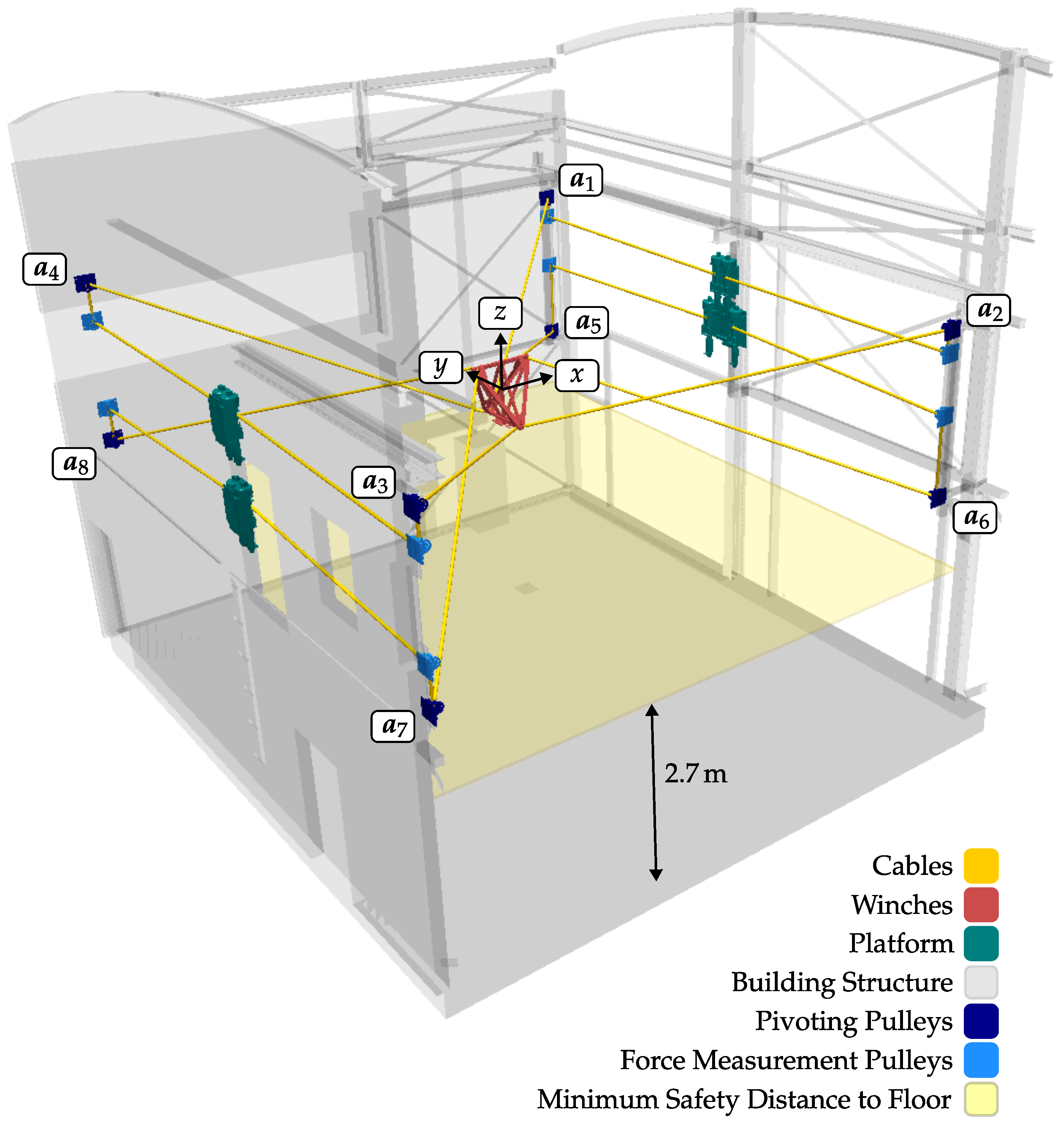
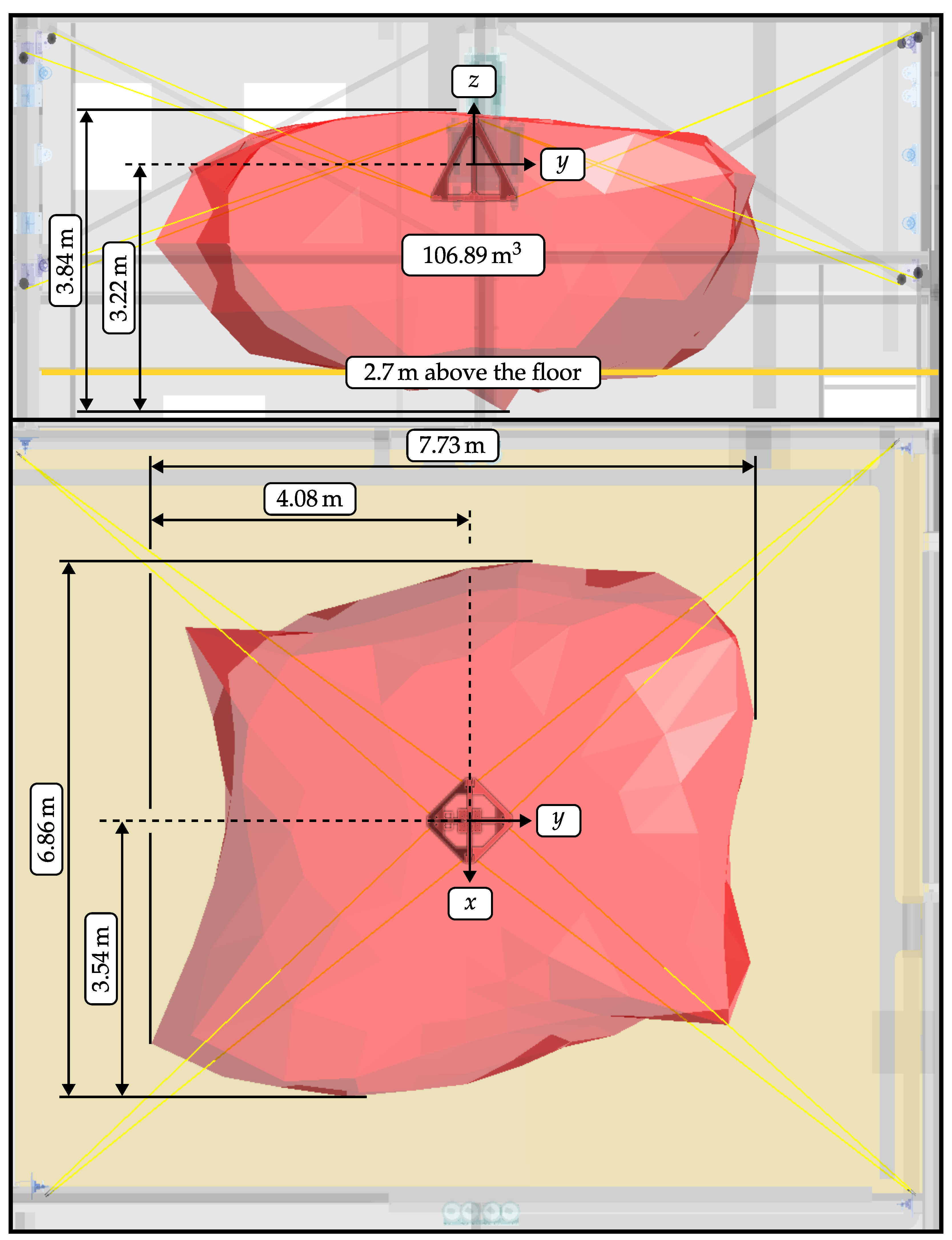
- The installation space of the robot is given by the steel frame structure of the room:10.2 m × 11.1 m × 3 ().
- The translational workspace should be as large as possible.
- The rotational workspace should cover rotations of ±20° around the horizontal x- and y-axis, ±10° around the vertical z-axis.
- The absolute accuracy should be in the magnitude of centimeters.
- The reuse of existing drive components, which constrains the torque and speed performance of the winches.
- A maximum platform mass of 40 without payload.
- A maximum payload of 60 , with a maximum size of 0.3 m × 0.3 m × 0.3 , attached at the bottom of the platform.
- A translational platform speed of up to 1.4 −1. Since for CDPRs the translational platform speed is equal to or higher than the cable speed [1], the maximum required cable speed is also defined as 1.4 −1.
3.2. Safety Requirements
- During normal operation, all components of the CDPR must stay 2.7 above the ground.
- If the platform is lowered under 2.7 for maintenance work, its speed is safely limited below 0.25 −1.
- The brakes of the winches must be redundant.
- The following safety functions (defined in [11]) must be electrically realized and implemented in the safety software:
- –
- Safe Torque Off (STO)
- –
- Safe Stop 1 (SS1) and Safe Stop 2 (SS2)
- –
- Safely Limited Position (SLP)
- –
- Safely Limited Speed (SLS)
- –
- Safe Brake Control (SBC)
- –
- Safe Brake Test (SBT)
- –
- Safely Limited Cable Force (SLCF)(The safety function SLCF is not explicitly defined in [11], where instead Safely Limited Torque (SLT) is specified, which serves a comparable purpose. For CDPRs, directly limiting the cable forces provides a more sensible safety constraint than motor torque, thereby ensuring that no damage occurs to the cables and cable-platform connectors due to overload.)
According to DIN EN ISO 13849-1 Safety of machinery—Safety-related parts of control systems [8], each safety function is assessed with regard to: severity of injury, frequency and/or exposure times to hazard and the possibility of avoiding or limiting harm. Based on the assessment, the required Performance Level r (PL r) is defined. In case of the IPAnema Safe, all safety functions must be implemented at the highest Performance Level e (PL e).
4. Design
4.1. Layout of the IPAnema Safe
- All moving components of the IPAnema Safe must be located above a height of 2.7 , thus eliminating the need for a safety housing.
- The winches are built without cable-guiding spools (see Section 4.2.3). Therefore, there has to be a distance of more than 4 between the drum of the winch and the first pulley to ensure proper spooling of the cable [12].
- For the safety function SLCF, the cable forces must be measured by safety-certified sensors.
- The number of pulleys per cable should be as small as possible to minimize cable bending cycles and thus increase the cable’s lifespan.
- Coming from the drum of the winch, the cable length between the drum and the last pulley before the platform has to be kept to a minimum and should be almost the same for each cable. This reduces cable elongation effects due to cable elasticity.
- There must be no collision between the cables and the steel structure of the hall.
- The space on the floor of the hall, occupied by components of the IPAnema Safe, should be kept to a minimum.
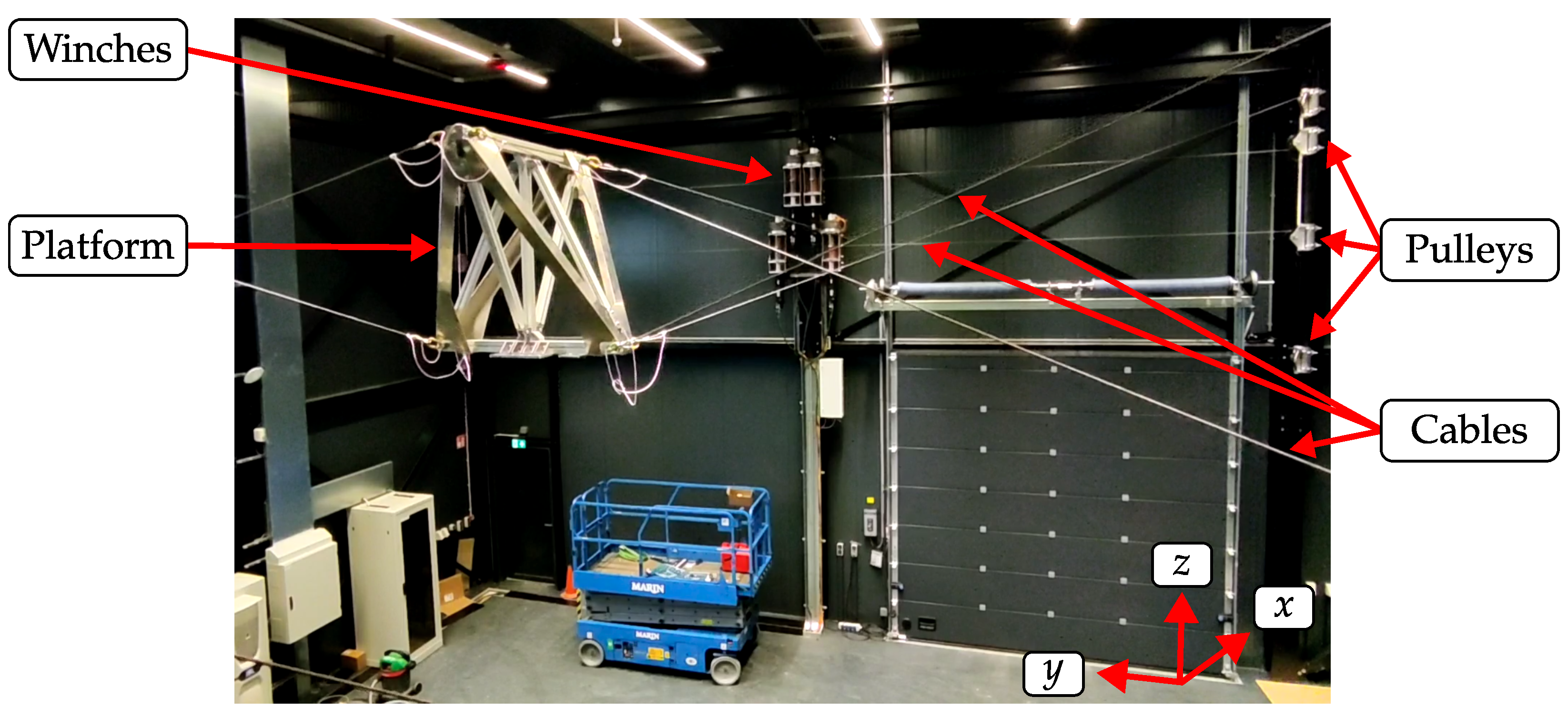
- The resulting layout of the cable robot is depicted in Figure 3. The winches are arranged in pairs in a vertical position. Each cable runs from its winch to a fixed force measurement pulley (light blue, Figure 3), which redirects the cable at a constant angle of around 90°. From there, it is guided to the bi of the platform via a pivoting pulley (dark blue, Figure 3).
4.2. Winches
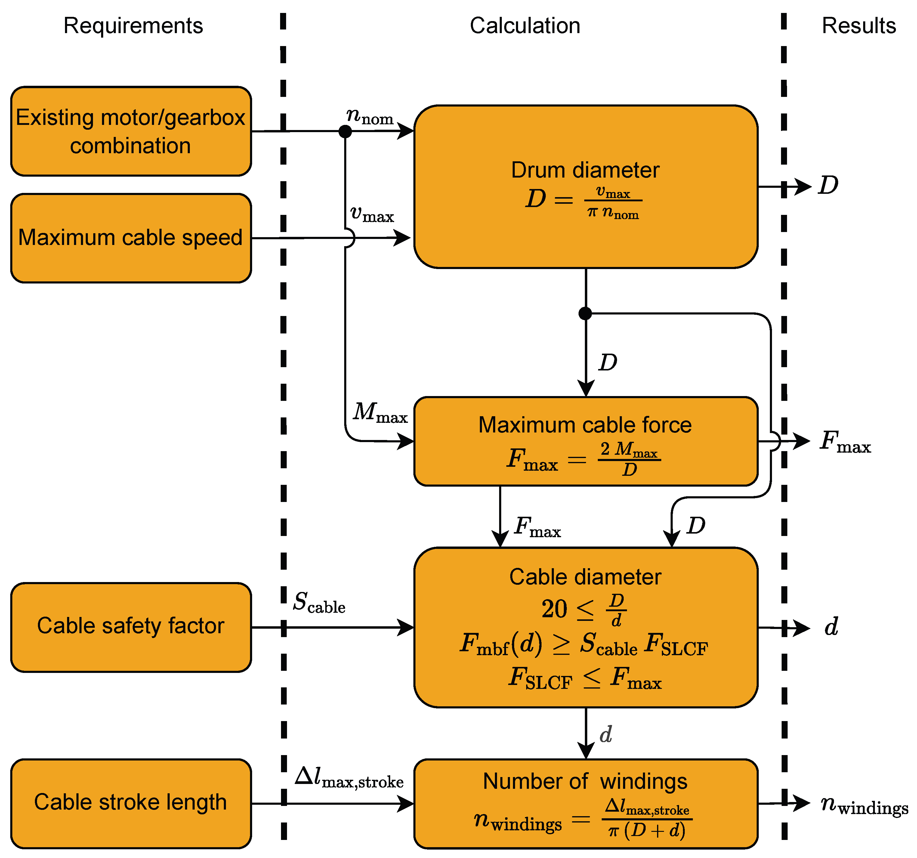
4.2.1. Design of the Drum
4.2.2. Safety Features: Redundant Brakes and Safety-Certified Encoders
4.2.3. Cable Guiding
4.2.4. Cable Securing Mechanism in Case of Cable Tension Loss
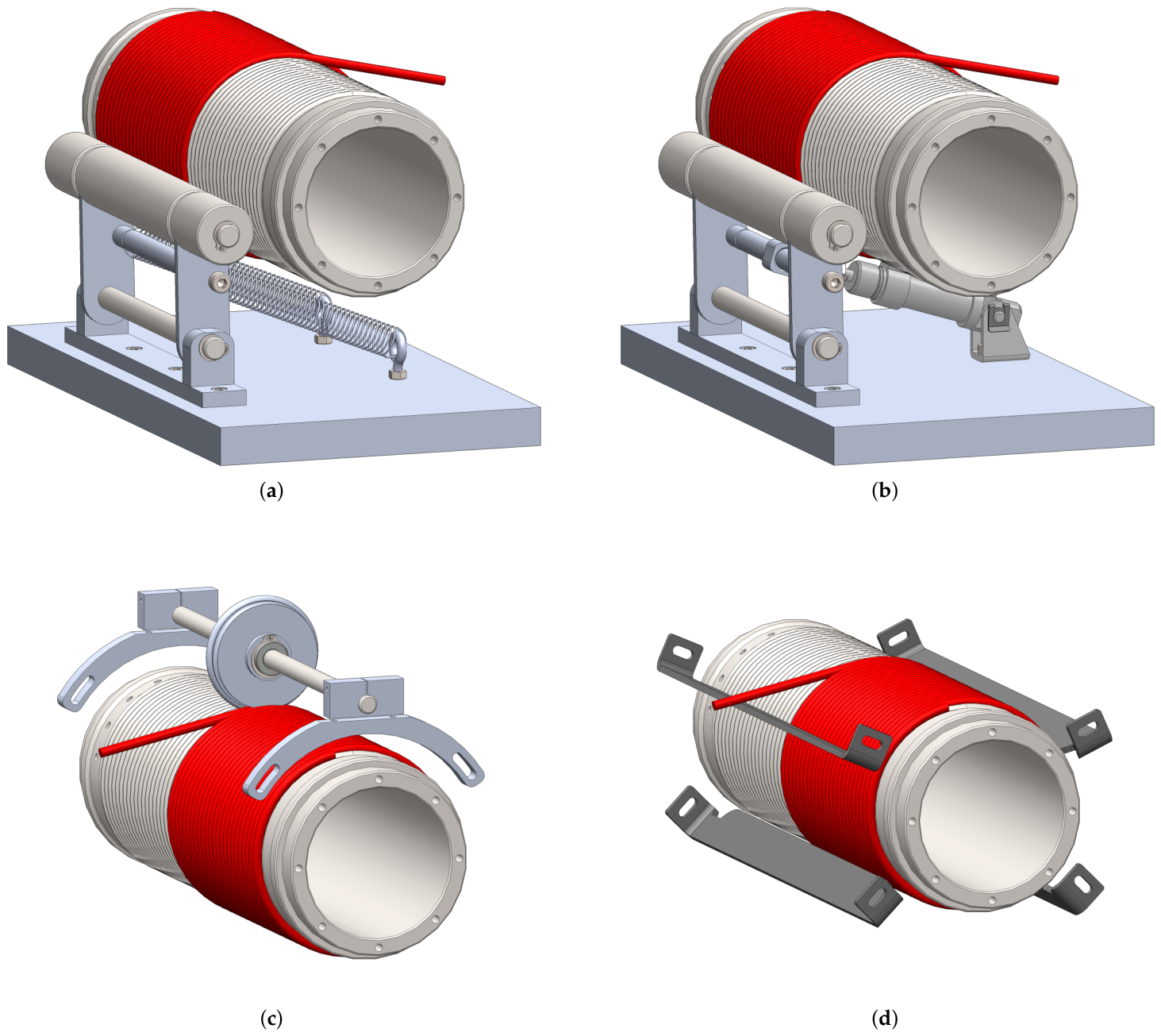
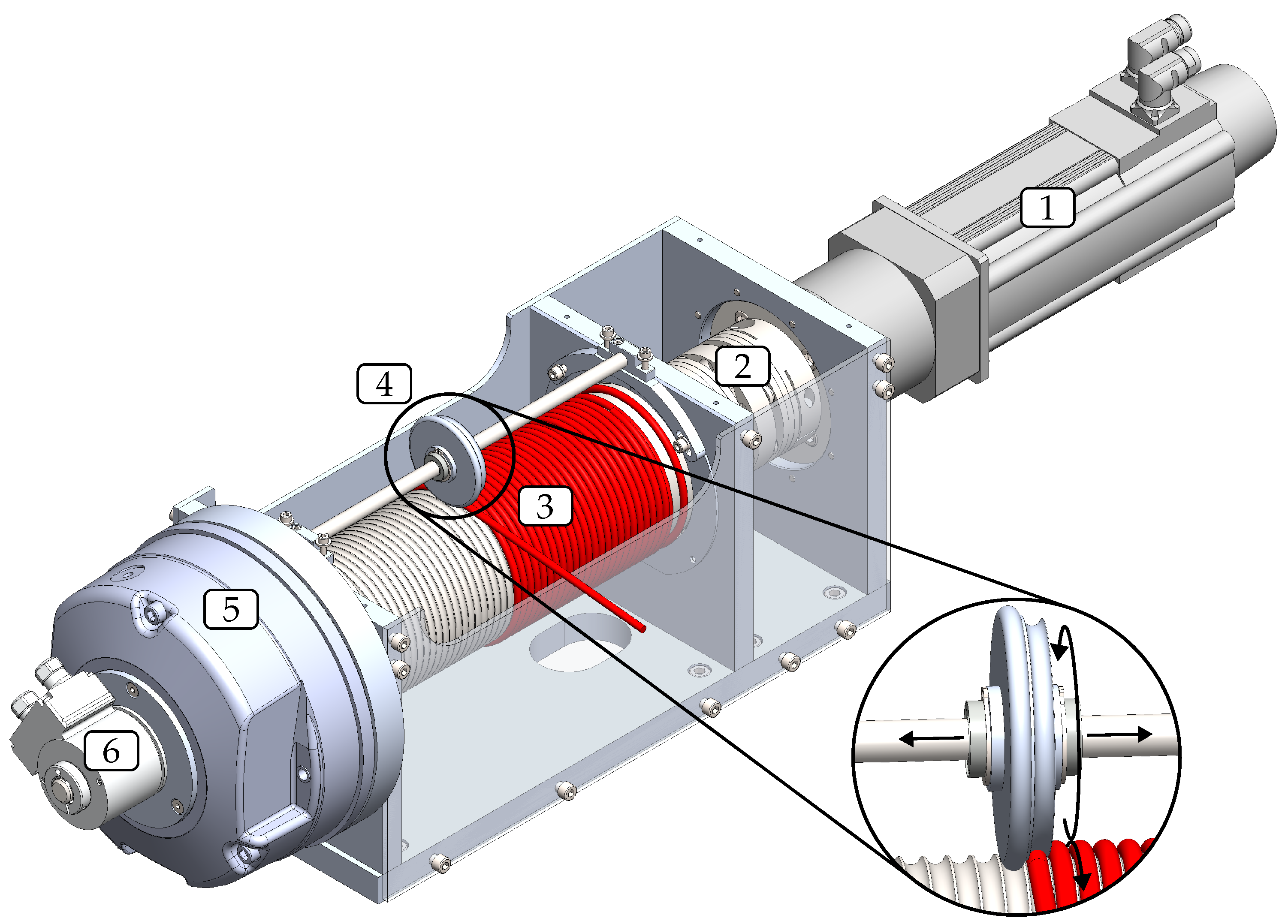
- Figure 5a: A wide pressure roller is designed, which rests on the cables over the entire length of the drum to press the cable into the grooves. The roller is pulled against the drum by springs.
- Figure 5b: Since the cable tensions are safely monitored by the safety-certified controller during normal operation of the robot, they do not lose their tension. Thus, the solution of Figure 5a can be enhanced by a pneumatic cylinder, so that the pressure roller can be pushed away from the drum if not needed and does not rest permanently on the spooled cable.
- Figure 5c: Instead of a wide pressure roller, a narrow pressure roller can be used, which presses solely on the cable at the point where the cable has the first or last contact to the drum while being spooled or unspooled. Guided by the cable and the grooves, the narrow pressure roller moves translationally up and down during the spooling and unspooling of the cable, parallel to the rotation axis of the drum. A detailed view of the mechanism can be seen in Figure 6.
- Figure 5d: Finally, four steel rails can be mounted evenly spaced around the drum’s axis. They extend the entire length of the drum and are positioned so that the correctly spooled cable does not touch the rail, yet is close enough to prevent the cable from skipping any grooves.
- In order to test the functionality of the proposed cable securing options, a prototype winch is built and mounted vertically. The following results are obtained by conducting various spooling tests.
4.3. Platform Model
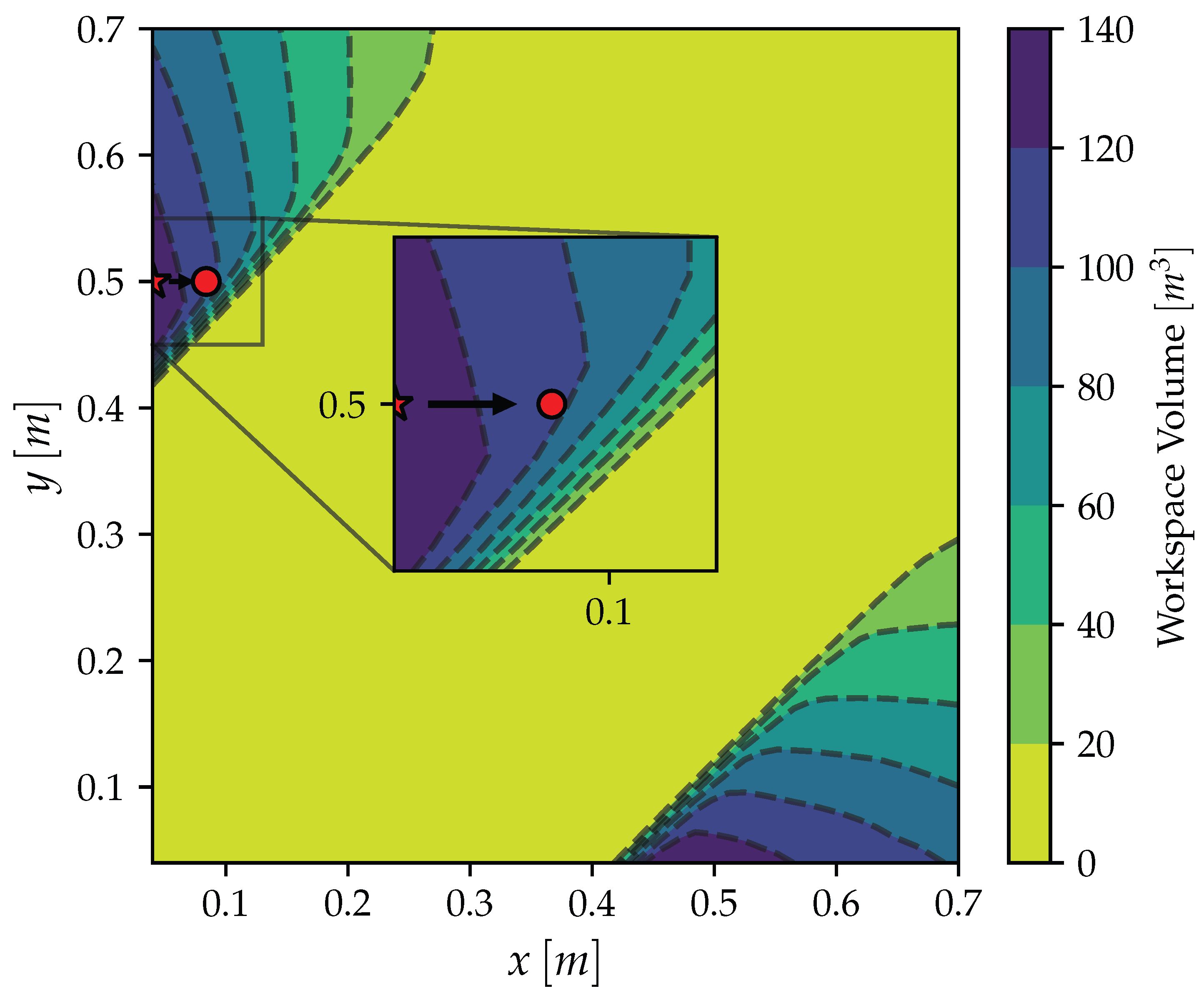
- Reduction of the dimension of the search space from 24 to 6 by restricting the platform design to be symmetric in the x- and y-directions.
- The distal anchor points are centered around the origin of their coordinate system in the z-direction, which further reduces the dimension of the search space to 5.
- The upper proximal anchor points are connected with the lower distal anchor points and vice versa in each quadrant of the -plane. This layout with crossed cables in the z-direction is a common choice for CDPRs to increase their workspace volume in the z-direction.
- This results in five free variables and z, which can be used to describe all distal anchor points :
- The optimized distal anchor points have a large z component, close to its maximum.
- The optimized value of the free variable is almost equal to and is almost equal to .
- For constant orientation, cable-cable-collision are effectively not constraining the workspace.
5. Functional Safety
5.1. Safely Limited Cable Force (SLCF)
5.2. Safely Limited Position (SLP) and Safely Limited Speed (SLS)
5.2.1. Amplification Between Cable Lengths/Speeds Tolerances and Platform Pose/Speed Deviations
5.2.2. Parameterization of the Safety Function Safely Limited Position (SLP)
5.2.3. Parameterization of the Safety Function Safely Limited Speed (SLS)
5.2.4. Verification and Experimental Validation of the Safety Functions
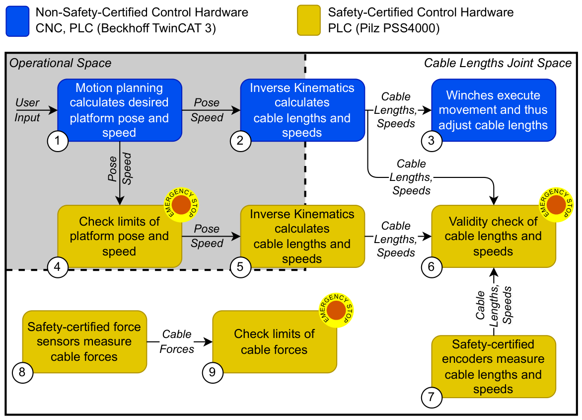
- SLCF: To validate the SLCF safety function, both the upper and lower cable force limits are exceeded for each cable in order to ensure that the safety-certified controller detects the limit violation and initiates an emergency stop.
- SLP: To validate the SLP safety function, two tests are carried out. First, the platform is commanded to a pose outside the safety position limits, where the resulting limit violation must be detected by the safety-certified controller and trigger an emergency stop (Figure 9, ➃). Second, the pose data transmission between the non-safety-certified controller and the safety-certified controller (Figure 9, connection between ➀ and ➃) is actively manipulated such that a constant pose is transmitted by the non-safety-certified controller. When the platform is subsequently commanded to move, the safety-certified controller must detect the incorrect pose data within the parameterized tolerance and trigger an emergency stop (Figure 9, ➅).
- SLS: The safety function SLS is, in principle, tested with the same two tests as the SLP safety function. For the first test, the platform is commanded to move at a speed beyond the limit of 0.25 −1. As soon as the speed limit is exceeded, the safety-certified controller must stop the robot by an emergency stop (Figure 9, ➃). In the second test, the data transmission between the safety-certified controller and the non-safety-certified controller is actively manipulated between ➀ and ➃, Figure 9, by keeping the transmitted speed constant. As soon as the platform is commanded to move, the safety-certified controller must detect the incorrect velocity data within the parameterized tolerance and subsequently stop the robot by an emergency stop (Figure 9, ➅).
- System performance to achieve the intended risk reduction: The system performance to achieve the intended risk reduction is measured according to DIN EN ISO 13855 Safety of machinery—Positioning of safeguards with respect to the approach of the human body [17]. Therefore, the distance traveled by the robot’s platform after an emergency stop is triggered at maximum speed in the negative z-direction is experimentally measured using a certified stopping performance device. To ensure that the platform stops above 2.7 , the lower workspace limit in the safety-certified controller is parameterized considering a buffer of 0.3 for the platform’s braking distance in addition to the 0.2 due to the possible pose uncertainty (Section 5.2.2). Consequently, the braking distance measured by the certified stopping performance device must not exceed 0.3 .Tests are performed at various -positions (in meters): , , , , and . Each test starts at , with the emergency stop triggered at . The tests are repeated 10 times at each -position. Across all tests, the maximum braking distance is measured as 0.233 , which is within the allocated buffer of 0.3 and verifies that the platform remains at least 2.7 above the floor in case of an emergency stop.
6. Conclusions
Author Contributions
Funding
Data Availability Statement
Conflicts of Interest
References
- Pott, A. Cable-Driven Parallel Robots: Theory and Application; Springer: Cham, Switzerland, 2018. [Google Scholar] [CrossRef] [Scilit]
- Surdilovic, D.; Bernhardt, R. STRING-MAN: A New Wire Robot for Gait Rehabilitation. In Proceedings of the IEEE International Conference on Robotics and Automation (ICRA ’04), New Orleans, LA, USA, 26 April–1 May 2004; Volume 2, pp. 2031–2036. [Google Scholar] [CrossRef] [Scilit]
- Otis, M.J.D.; Comtois, S.; Laurendeau, D.; Gosselin, C. Human Safety Algorithms for a Parallel Cable-Driven Haptic Interface. In Proceedings of the Brain, Body and Machine, Montreal, QC, Canada, 10–13 November 2010; Springer: Berlin/Heidelberg, Germany, 2010; pp. 187–200. [Google Scholar] [CrossRef] [Scilit]
- Merlet, J.P. MARIONET, A Family of Modular Wire-Driven Parallel Robots. In Advances in Robot Kinematics: Motion in Man and Machine; Springer: Dordrecht, The Netherlands, 2010; pp. 53–61. [Google Scholar] [CrossRef] [Scilit]
- Tempel, P.; Schnelle, F.; Pott, A.; Eberhard, P. Design and Programming for Cable-Driven Parallel Robots in the German Pavilion at the EXPO 2015. Machines 2015, 3, 223–241. [Google Scholar] [CrossRef] [Scilit]
- Miermeister, P.; Lachele, M.; Boss, R.; Masone, C.; Schenk, C.; Tesch, J.; Kerger, M.; Teufel, H.; Pott, A.; Bulthoff, H.H. The CableRobot Simulator Large Scale Motion Platform Based on Cable Robot Technology. In Proceedings of the 2016 IEEE/RSJ International Conference on Intelligent Robots and Systems (IROS), Daejeon, Republic of Korea, 9–14 October 2016. [Google Scholar] [CrossRef] [Scilit]
- Maritime Research Institute Netherlands (MARIN). Integrating eXtended Reality at New MX Lab: A LEVIATHAN Amongst Simulators. 2024. Available online: https://magazine.marin.nl/marin-report-140/mx-lab (accessed on 22 October 2024).
- DIN EN ISO 13849-1:2023; Safety of Machinery—Safety-Related Parts of Control Systems—Part 1: General Principles for Design. International Organization for Standardization: Berlin, Germany, 2023.
- Bons, A. MARIN Builds Most Realistic Simulator Centre for Maritime Operations in the World. 2022. Available online: https://www.marin.nl/en/publications/marin-builds-most-realistic-simulator-centre-for-maritime-operations-in-the-world (accessed on 21 May 2026).
- DIN EN ISO 12100:2011-03; Safety of Machinery—General Principles for Design—Risk Assessment and Risk Reduction. Deutsches Institut für Normung: Berlin, Germany, 2011; German edition: Sicherheit von Maschinen—Allgemeine Gestaltungsleitsätze—Risikobeurteilung und Risikominderung.
- Pilz GmbH & Co. KG. Safety Compendium. 2017. Available online: https://www.pilz.com/mam/pilz/content/editors_mm/safety_compendium_en_2017_12_low.pdf (accessed on 16 April 2025).
- Martin, C.; Fabritius, M.; Lehnertz, C.; Jurašić, P.; Stoll, J.T.; Ernst, M.O.; Kraus, W.; Pott, A. IPAnema Silent: A CDPR for Spatial Hearing Experiments. In Proceedings of the International Conference on Cable-Driven Parallel Robots; Springer: Cham, Switzerland, 2023; pp. 407–418. [Google Scholar] [CrossRef] [Scilit]
- Deutsche Gesetzliche Unfallversicherung (DGUV). DGUV Information 215-313—Loads over Positions Where People May be Present; Deutsche Gesetzliche Unfallversicherung e.V. (DGUV): Berlin, Germany, 2020; German edition: Lasten über Personen. [Google Scholar]
- DIN 15020-1:1974-02; Lifting Appliances—Principles Relating to Rope Drives—Calculation and Construction. Deutsches Institut für Normung: Berlin, Germany, 1974; German edition: Hebezeuge—Grundsätze für Seiltriebe, Berechnung und Ausführung.
- German Social Accident Insurance (DGUV). FBHM-005—Gravity-Loaded Axes—Vertical Axes; German Social Accident Insurance (DGUV): Berlin, Germany, 2021; German edition: Schwerkraftbelastete Achsen—Vertikalachsen, Webcode: p021977. [Google Scholar]
- Idà, E.; Mattioni, V. Cable-Driven Parallel Robot Actuators: State of the Art and Novel Servo-Winch Concept. Actuators 2022, 11, 290. [Google Scholar] [CrossRef] [Scilit]
- DIN EN ISO 13855:2025-10; Safety of Machinery—Positioning of Safeguards with Respect to the Approach of the Human Body. Deutsches Institut für Normung: Berlin, Germany, 2025; German edition: Sicherheit von Maschinen—Anordnung von Schutzeinrichtungen im Hinblick auf Annäherung des menschlichen Körpers.




| Nominal rotation speed | nnom | 203 min−1 |
| Maximum torque | Mmax | 255 N m |
| Maximum cable speed | vmax | 1.4 m s−1 |
| Maximum cable stroke | Δlmax,stroke | 19.05 m |
| Drum diameter | D | 131.7 mm |
| Maximum cable force | Fmax | 3878 N |
| Safely limited cable force | FSLCF | 3350 N |
| Cable diameter | d | 6 mm |
| Cable minimum breaking force | Fmbf | 33.1 kN |
| Cable safety factor | Scable | 9.88 |
| Number of windings | nwindings | 44 |
| Cable i | a [m] | b [m] |
|---|---|---|
| 1 | ||
| 2 | ||
| 3 | ||
| 4 | ||
| 5 | ||
| 6 | ||
| 7 | ||
| 8 |
Disclaimer/Publisher’s Note: The statements, opinions and data contained in all publications are solely those of the individual author(s) and contributor(s) and not of MDPI and/or the editor(s). MDPI and/or the editor(s) disclaim responsibility for any injury to people or property resulting from any ideas, methods, instructions or products referred to in the content. |
© 2026 by the authors. Licensee MDPI, Basel, Switzerland. This article is an open access article distributed under the terms and conditions of the Creative Commons Attribution (CC BY) license.
Share and Cite
Martin, C.; Fabritius, M.; Lehnertz, C.; Traub, J.; Stoll, J.T.; Kraus, W.; Pott, A. IPAnema Safe: A Cable-Driven Parallel Robot for Safe Operation Above People. Robotics 2026, 15, 124. https://doi.org/10.3390/robotics15070124
Martin C, Fabritius M, Lehnertz C, Traub J, Stoll JT, Kraus W, Pott A. IPAnema Safe: A Cable-Driven Parallel Robot for Safe Operation Above People. Robotics. 2026; 15(7):124. https://doi.org/10.3390/robotics15070124
Chicago/Turabian StyleMartin, Christoph, Marc Fabritius, Christian Lehnertz, Jakob Traub, Johannes T. Stoll, Werner Kraus, and Andreas Pott. 2026. "IPAnema Safe: A Cable-Driven Parallel Robot for Safe Operation Above People" Robotics 15, no. 7: 124. https://doi.org/10.3390/robotics15070124
APA StyleMartin, C., Fabritius, M., Lehnertz, C., Traub, J., Stoll, J. T., Kraus, W., & Pott, A. (2026). IPAnema Safe: A Cable-Driven Parallel Robot for Safe Operation Above People. Robotics, 15(7), 124. https://doi.org/10.3390/robotics15070124