Article

IPAnema Safe: A Cable-Driven Parallel Robot for Safe Operation Above People

1
Research Division Automation and Robotics, Fraunhofer Institute for Manufacturing Engineering and Automation IPA, 70569 Stuttgart, Germany
2
Institute for Control Engineering of Machine Tools and Manufacturing Units (ISW), University of Stuttgart, 70511 Stuttgart, Germany
*
Author to whom correspondence should be addressed.
Robotics 2026, 15(7), 124; https://doi.org/10.3390/robotics15070124
Submission received: 24 April 2026 / Revised: 24 June 2026 / Accepted: 26 June 2026 / Published: 30 June 2026
(This article belongs to the Section Intelligent Robots and Mechatronics)

Abstract

Training ship crews for new scenarios at sea in reproducible sea conditions is weather-dependent and dangerous. The Maritime Research Institute Netherlands (MARIN) addresses this issue by offering a variety of different simulators to safely train people onshore. For scenarios involving a swinging hook or a ladder for a pilot boarding a ship in turbulent sea conditions, a safe cable-driven parallel robot, the IPAnema Safe, is developed. Its safety features allow its platform to move above people during training scenarios. Therefore, in addition to standard safety features and a proper mechanical design, the safety functions Safely Limited Position (SLP) and Safely Limited Speed (SLS) for a cable-driven parallel robot are implemented on safety-certified hardware with Performance Level e (PL e). This work presents the design process and implementation of the IPAnema Safe, focusing on its layout, winches, platform optimization and functional safety features.

1. Introduction

A cable-driven parallel robot (CDPR) is a type of parallel robot that uses cables instead of rigid links to manipulate a platform. It consists of a fixed base frame from which multiple cables are spooled by winches. The cables connect the fixed base frame with a moving platform. By controlling the lengths of these cables, the position and orientation of the platform can be manipulated within its workspace. Advantages of CDPRs, compared to other robot types, are their potential for very large workspaces, high payloads and significant dynamic capabilities due to their lightweight structure [1].
A field of application for CDPRs, which benefits from these advantages, is motion simulation, which often incorporates direct human interaction with the robot. In such environments, with people near the CDPR, functional safety becomes paramount. Surdilovic et al. present the STRING-MAN, a wire robot prototype developed for gait rehabilitation to support patients with motor impairments during training [2]. Since there is a direct physical human–robot connection, safety is an important but still open issue. Otis et al. present safety control methods for a CDPR with a haptic interface for interaction with virtual objects [3]. Based on a risk analysis, the paper addresses strategies in case of sensor faults, the platform leaving the workspace limits and cable interference. Merlet presents another rehabilitation robot (MARIONET-REHAB), based on a wire-driven parallel robot [4]. The robot is intended for arm training after a loss of arm coordination. Furthermore, Merlet proposes the MARIONET-CRANE and MARIONET-ASSIST for rescue operations and assistance for the elderly and people with disabilities, lifting objects as well as individuals. However, the topic of safety is not addressed within the paper. The development of two CDPRs designed to fly above crowds at the EXPO 2015 is described in [5]. Regarding the safety of the robots, the paper outlines the development of a path planning software that verifies whether a desired trajectory adheres to defined safety limits (regarding the workspace, cable forces, velocity, acceleration, and collisions) before execution. Functional safety is also a critical requirement for the CableRobot Simulator at the Max Planck Institute for Biological Cybernetics, which is designed to move occupants within its large workspace [6].
Except for the CableRobot Simulator, the aforementioned literature omits whether safety-certified controllers and sensors are used to implement safety features that are required when robots operate in close vicinity of people. Compared to standard PLCs, safety-certified controllers provide only a limited set of functionalities and lower performance. This poses a challenge to the implementation of safety functionalities, monitoring the kinematics of CDPRs, due to their parallel structure.
This paper presents the development and realization process of the IPAnema Safe CDPR, shown in Figure 1. Commissioned for the Maritime Research Institute Netherlands (MARIN) as part of their Maritime eXperience Lab (MX Lab), the IPAnema Safe is designed for the Safe Operations and Human Factors research program [7]. Its primary objective is to provide a safe and controlled environment for training ship crews in complex maritime operations. This is achieved through the integration of specific safety functionalities, implemented on safety-certified hardware, enabling the robot to operate safely above and interact with personnel during training scenarios.
Generally, if the words ’safe’, ’safely’, ’safety’ or ’safety-certified’ are used in the context of control in the following paper, they indicate that the associated hardware or functionality of the control system is safe according to DIN EN ISO 13849-1 Safety of machinery—Safety-related parts of control systems [8].
The remainder of this paper is organized as follows: Section 2 describes a potential application scenario for the IPAnema Safe. Section 3 outlines the key technical and safety requirements driving the robot’s design. The design process itself is detailed in Section 4. Section 5 focuses on the implementation of functional safety features. Finally, the paper concludes with a summary of the work and potential future directions.

2. Use Case

The primary application envisioned for the IPAnema Safe is the training of maritime personnel for complex and potentially hazardous operations. This necessitates the robot’s capability to safely operate above trainees and, in specific scenarios, to interact with them.
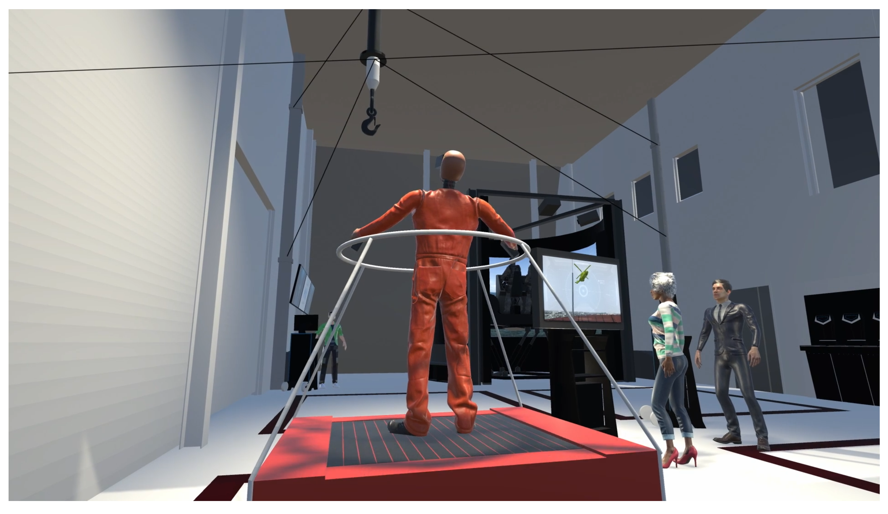
A representative training scenario involves simulating the dynamic behavior of a hook dangling from an approaching helicopter as it nears a ship experiencing rough sea conditions (visualized in Figure 2). In this simulation, the IPAnema Safe’s platform, carrying an auxiliary winch, replicates the motion of the winch hook resulting from the helicopter’s movement. The objective for the trainee is to practice catching this moving hook, a task that is both challenging and dangerous when performed on the open sea.
Direct physical interaction between personnel and the robot during operation introduces complexities regarding compliance with applicable safety standards. Standard operation mandates that all moving parts remain above a height of 2.7 m . Therefore, scenarios requiring the platform or its payload to descend below this height, while a person is present, necessitate an additional risk assessment. Acceptance of the residual risk identified in such an assessment may be justified by comparing the controlled, simulated environment’s safety level to the significantly higher risks associated with performing the equivalent task on the open sea.

3. Requirements

The requirements based on which the IPAnema Safe is designed originate from the boundary conditions of the installation space, its intended use cases, and the corresponding safety regulations.

3.1. Mechanical and Physical Requirements

The mechanical requirements are as follows:
  • The installation space of the robot is given by the steel frame structure of the room:
    10.2 m × 11.1 m × 3 m ( x × y × z ).
  • The translational workspace should be as large as possible.
  • The rotational workspace should cover rotations of ±20° around the horizontal x- and y-axis, ±10° around the vertical z-axis.
  • The absolute accuracy should be in the magnitude of centimeters.
  • The reuse of existing drive components, which constrains the torque and speed performance of the winches.
  • A maximum platform mass of 40 k g without payload.
  • A maximum payload of 60 k g , with a maximum size of 0.3 m × 0.3 m × 0.3 m , attached at the bottom of the platform.
  • A translational platform speed of up to 1.4 m s −1. Since for CDPRs the translational platform speed is equal to or higher than the cable speed [1], the maximum required cable speed is also defined as 1.4 m s −1.

3.2. Safety Requirements

Since the IPAnema Safe is intended to operate safely above people, a risk assessment according to DIN EN ISO 12100 Safety of machinery—General principles for design—Risk assessment and risk reduction [10] is conducted. Based on this risk assessment, the most important measures for risk reduction lead to the following safety requirements:
  • During normal operation, all components of the CDPR must stay 2.7 m above the ground.
  • If the platform is lowered under 2.7 m for maintenance work, its speed is safely limited below 0.25 m s −1.
  • The brakes of the winches must be redundant.
  • The following safety functions (defined in [11]) must be electrically realized and implemented in the safety software:
    Safe Torque Off (STO)
    Safe Stop 1 (SS1) and Safe Stop 2 (SS2)
    Safely Limited Position (SLP)
    Safely Limited Speed (SLS)
    Safe Brake Control (SBC)
    Safe Brake Test (SBT)
    Safely Limited Cable Force (SLCF)
    (The safety function SLCF is not explicitly defined in [11], where instead Safely Limited Torque (SLT) is specified, which serves a comparable purpose. For CDPRs, directly limiting the cable forces provides a more sensible safety constraint than motor torque, thereby ensuring that no damage occurs to the cables and cable-platform connectors due to overload.)
    According to DIN EN ISO 13849-1 Safety of machinery—Safety-related parts of control systems [8], each safety function is assessed with regard to: severity of injury, frequency and/or exposure times to hazard and the possibility of avoiding or limiting harm. Based on the assessment, the required Performance Level r (PL r) is defined. In case of the IPAnema Safe, all safety functions must be implemented at the highest Performance Level e (PL e).

4. Design

The IPAnema Safe is designed as a redundantly-constrained CDPR with six degrees-of-freedom (DoF) and eight cables. Its geometry parameters are described using the notation from [1]. For each cable i, the vector ai describes the position of its fixed proximal anchor point on the CDPR’s frame. The vector bi denotes the distal anchor point on the platform. The following sections describe the design process of the IPAnema Safe.

4.1. Layout of the IPAnema Safe

The steel structure of the MX Lab is utilized to mount the components of the cable robot. The statics of this structure is designed to withstand the maximum forces exerted by the IPAnema Safe. To maximize the robot’s workspace, its proximal anchor points are positioned in the corners of the available installation space. The positioning of the winches is determined by considering the following aspects:
  • All moving components of the IPAnema Safe must be located above a height of 2.7 m , thus eliminating the need for a safety housing.
  • The winches are built without cable-guiding spools (see Section 4.2.3). Therefore, there has to be a distance of more than 4 m between the drum of the winch and the first pulley to ensure proper spooling of the cable [12].
  • For the safety function SLCF, the cable forces must be measured by safety-certified sensors.
  • The number of pulleys per cable should be as small as possible to minimize cable bending cycles and thus increase the cable’s lifespan.
  • Coming from the drum of the winch, the cable length between the drum and the last pulley before the platform has to be kept to a minimum and should be almost the same for each cable. This reduces cable elongation effects due to cable elasticity.
  • There must be no collision between the cables and the steel structure of the hall.
  • The space on the floor of the hall, occupied by components of the IPAnema Safe, should be kept to a minimum.
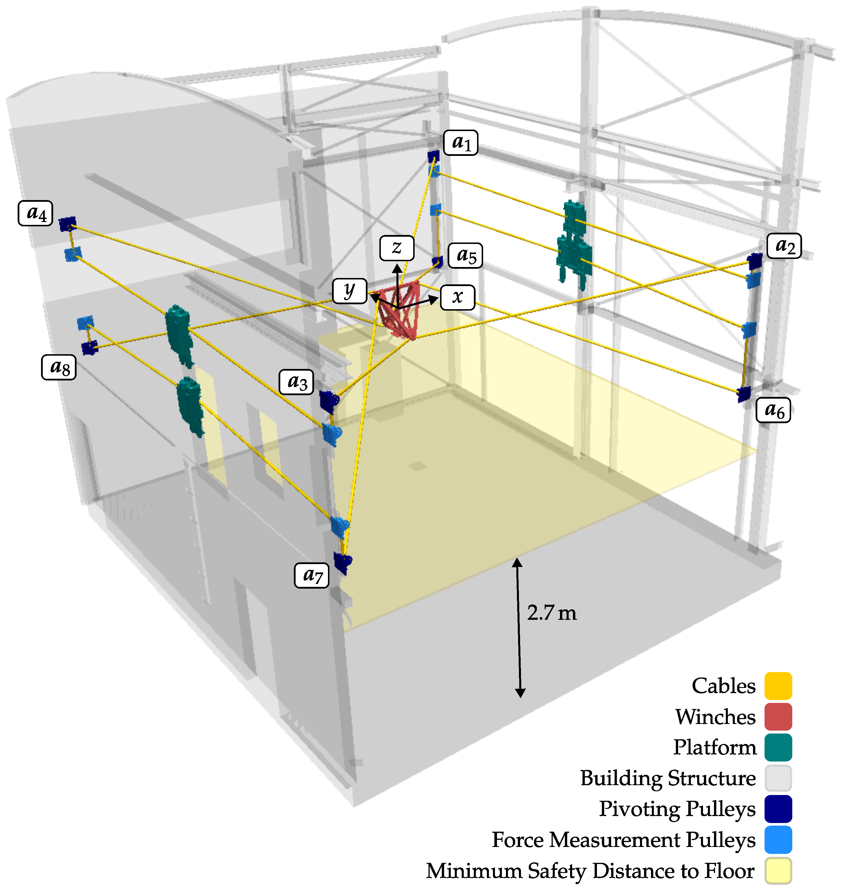
  • The resulting layout of the cable robot is depicted in Figure 3. The winches are arranged in pairs in a vertical position. Each cable runs from its winch to a fixed force measurement pulley (light blue, Figure 3), which redirects the cable at a constant angle of around 90°. From there, it is guided to the bi of the platform via a pivoting pulley (dark blue, Figure 3).

4.2. Winches

In the following, the design of the winches is presented, focusing on the design of the drum, the safety-certified brakes and encoders, the cable guiding and the cable securing mechanism in case of tension loss.

4.2.1. Design of the Drum

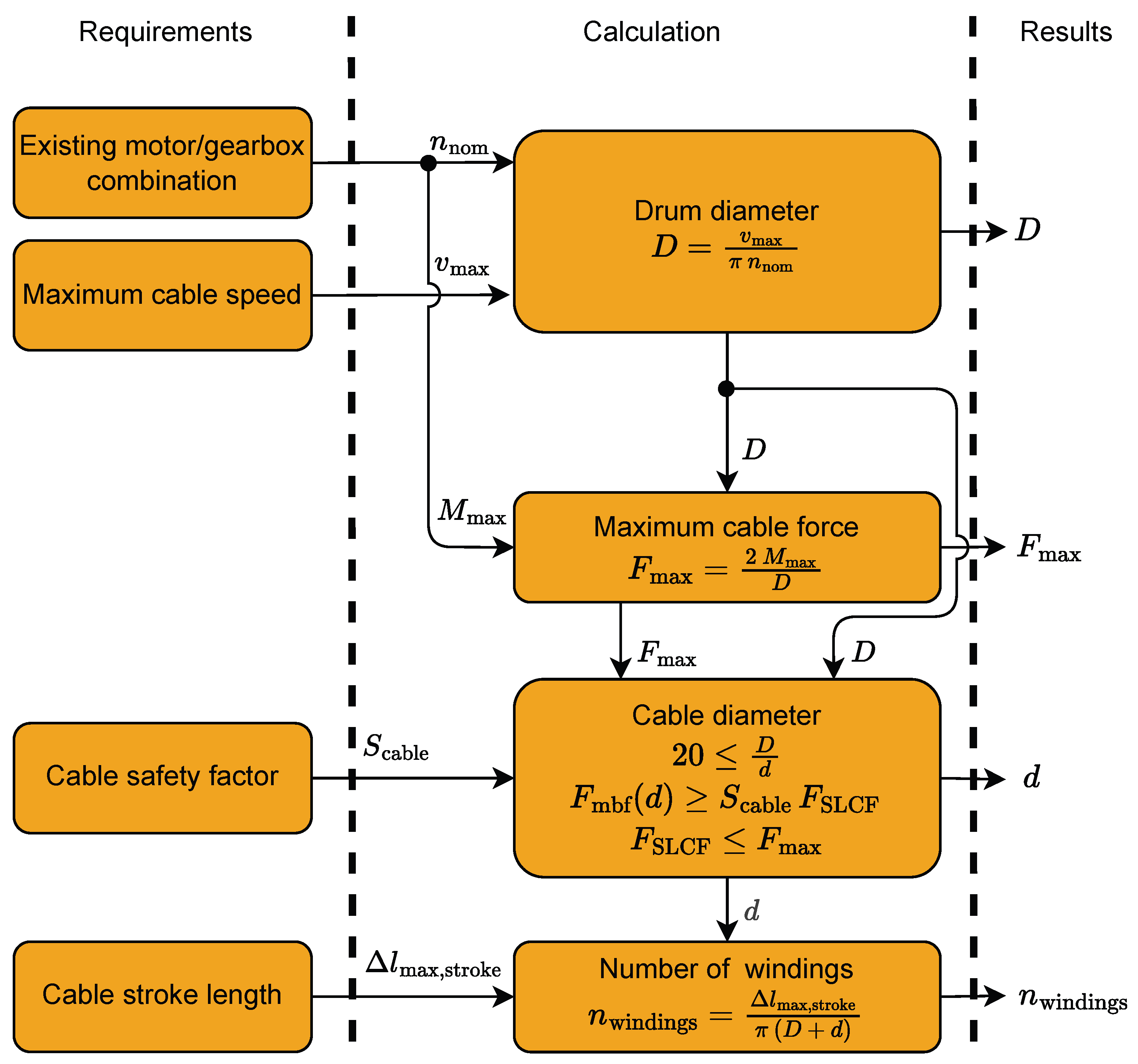
The drums of the winches are designed according to the procedure visualized in Figure 4. The numerical values of the parameters can be found in Table 1. The values of the variables transferred from the column Requirements to Calculation in Figure 4 are defined by the requirements or standards, the values transferred from Calculation to Results are the results from the design calculations.
Starting with the two requirements: the reuse of the existing motor/gearbox combination (nominal rotation speed nnom) and maximum cable speed (vmax), the drum diameter (D) is determined. With the resulting drum diameter and the maximum motor torque (Mmax), the maximum cable force (Fmax) is defined. To choose the cable diameter (d), the references [13,14] are taken into account. In case of the anticipated runtime and the pulley arrangement of the IPAnema Safe, the relation D 20 d is defined as per [14]. The largest possible diameter (rounded to the nearest millimeter) that satisfies the condition is less than 6 m m . According to [13] (Table 1), a safety factor (Scable) of 10 is required for steel cables holding loads above people. Consequently, a cable with a diameter of 6 m m and a minimum breaking force (Fmbf) of 33.1 k N is chosen. The maximum cable force (Fmax) is reduced by the safety function SLCF to FSLCF to account for the required safety factor Scable. Thus, a safety factor of 9.88 is achieved, which is sufficiently close to 10. Finally, the number of cable windings can be calculated with the maximum cable stroke (Δlmax,stroke). The maximum cable stroke is estimated by the diagonal of the IPAnema Safe installation space plus an additional margin. After the determination of these parameters, the drum is finalized by designing the grooves according to [14].

4.2.2. Safety Features: Redundant Brakes and Safety-Certified Encoders

The winches are categorized as gravity-loaded axes operating above persons. In the event of a power loss and without braking systems, the platform and cables would descend uncontrollably. This must be accounted for in the risk assessment according to [15]. To safely prevent such a failure, the winches are equipped with redundant brakes: a built-in brake in the motor and an additional safety-certified brake directly attached to the drum. Furthermore, a safety-certified encoder is mounted directly on the drum to ensure safe position monitoring.

4.2.3. Cable Guiding

Ensuring correct cable spooling on the drum is crucial for the functionality of the winches and to prevent damage to the cables. This can be achieved in multiple ways. A cable guiding spool can be designed, or the whole drum can be moved translationally during the spooling and unspooling process [16].
For the winches of the IPAnema Safe, a simple option without a cable guiding mechanism is chosen. The cable is guided by the grooves on the drum only. Previous experiments at Fraunhofer IPA have shown that this principle works only if the angle of deflection between the cable’s maximum and minimum position on the drum is less than 6° [12]. The IPAnema Safe layout is designed to meet this condition with a distance of more than 4 m between the winch drums and the force measurement pulleys.

4.2.4. Cable Securing Mechanism in Case of Cable Tension Loss

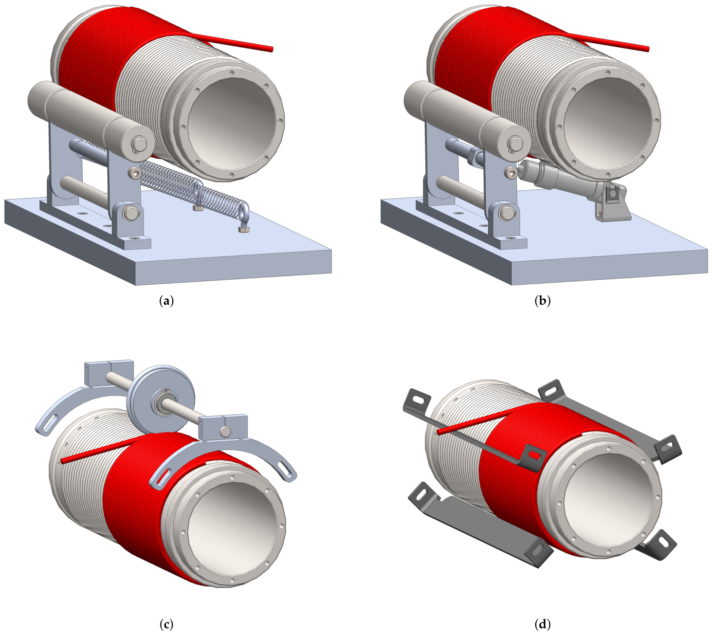
The vertical installation of the winches poses a challenge for the proper spooling of the cables onto the drum in case of cable tension loss. Due to gravity, a loose cable would come out of its groove and hang down on the drum. This leads to spooling errors, which result in positioning errors and may damage the steel cable. A loss of cable tension can occur, for example, during maintenance work. To avoid this, four ways of securing the cable on the drum are designed. Conceptual drawings of the cable securing mechanisms are shown in Figure 5 and explained in the following:
  • Figure 5a: A wide pressure roller is designed, which rests on the cables over the entire length of the drum to press the cable into the grooves. The roller is pulled against the drum by springs.
  • Figure 5b: Since the cable tensions are safely monitored by the safety-certified controller during normal operation of the robot, they do not lose their tension. Thus, the solution of Figure 5a can be enhanced by a pneumatic cylinder, so that the pressure roller can be pushed away from the drum if not needed and does not rest permanently on the spooled cable.
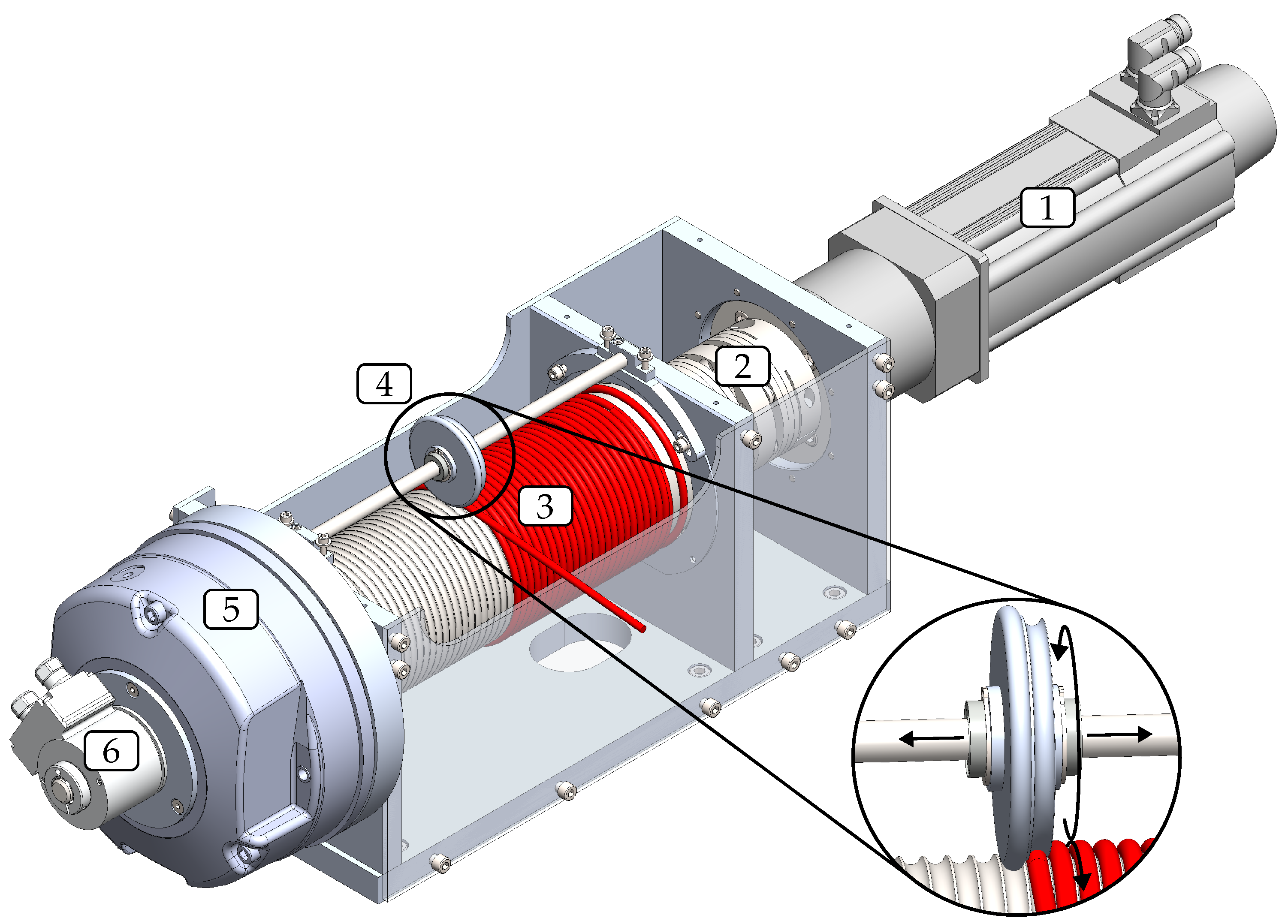
  • Figure 5c: Instead of a wide pressure roller, a narrow pressure roller can be used, which presses solely on the cable at the point where the cable has the first or last contact to the drum while being spooled or unspooled. Guided by the cable and the grooves, the narrow pressure roller moves translationally up and down during the spooling and unspooling of the cable, parallel to the rotation axis of the drum. A detailed view of the mechanism can be seen in Figure 6.
  • Figure 5d: Finally, four steel rails can be mounted evenly spaced around the drum’s axis. They extend the entire length of the drum and are positioned so that the correctly spooled cable does not touch the rail, yet is close enough to prevent the cable from skipping any grooves.
  • In order to test the functionality of the proposed cable securing options, a prototype winch is built and mounted vertically. The following results are obtained by conducting various spooling tests.
The solution depicted in Figure 5d does not work as intended. In case the cable direction deviates from the groove direction during the spooling, the cable is squeezed in the slit between the border of the groove and the steel rail and jumps to the next groove. This can even destroy the structure of the steel cable. The solutions in Figure 5a–c work as intended. The disadvantage of Figure 5a is that there is translational friction between the cable and the pressure roller, resulting in wear on both sides. Figure 5b is the most complex solution as it requires pressured air, an additional actuator and control. Furthermore, for the solutions in Figure 5a,b, the point at which the pressure roller presses on the cable is a quarter turn away from the point at which the cable makes first or last contact with the drum during spooling or unspooling. If the cable direction deviates from the groove direction during the spooling, it is corrected only after a quarter-turn. This results in friction between the cable and the border of the groove and thus cable wear. Finally, the decision is made in favor of solution Figure 5c due to the simple design and best functionality.
The final winch design with its individual parts is shown in Figure 6. All winches of the IPAnema Safe are identical in design and consist of a motor from Lenze with a built-in brake and an encoder (1), a clutch (2), a drum with a cable (3), a narrow pressure roller (4), an additional safety-certified brake from Mayr (5) and a safety-certified encoder from Pilz (6).

4.3. Platform Model

The platform of the IPAnema Safe is designed to maximize the volume V 𝒲 TO of its total-orientation workspace 𝒲TO. This workspace 𝒲TO is defined as the set of all platform positions where, for all platform orientations in a given set, the wrench-feasibility and cable-cable-collision criteria are satisfied. The wrench-feasibility (evaluated with the advanced closed-form method [1], a platform mass of 40 k g and a payload of 60 k g ) and cable-cable-collision criteria are assessed using the methods proposed in [12]. A global optimization algorithm is used to find the platform geometry (i.e., the positions of the distal anchor points b i ), which yields the maximum of V 𝒲 TO . To make this optimization problem tractable, the following assumptions and simplifications are made:
  • Reduction of the dimension of the search space from 24 to 6 by restricting the platform design to be symmetric in the x- and y-directions.
  • The distal anchor points b i are centered around the origin of their coordinate system in the z-direction, which further reduces the dimension of the search space to 5.
  • The upper proximal anchor points are connected with the lower distal anchor points and vice versa in each quadrant of the x y -plane. This layout with crossed cables in the z-direction is a common choice for CDPRs to increase their workspace volume in the z-direction.
  • This results in five free variables x 1 , x 2 , y 1 , y 2 and z, which can be used to describe all distal anchor points b i :
b 1 = x 1 y 1 z T , b 5 = x 2 y 2 z T ,
b 2 = x 1 y 1 z T , b 6 = x 2 y 2 z T ,
b 3 = x 1 y 1 z T , b 7 = x 2 y 2 z T ,
b 4 = x 1 y 1 z T , b 8 = x 2 y 2 z T
Finally, this optimization problem can be stated as:
arg max x 1 , x 2 , y 1 , y 2 , z   V 𝒲 TO ( x 1 , x 2 , y 1 , y 2 , z )
The optimization is implemented using the differential evolution algorithm provided by the SciPy v1.10.1 Python library (https://docs.scipy.org/doc/scipy/reference/generated/scipy.optimize.differential_evolution.html, accessed on 10 April 2023). Except for the free variables, all other parameter settings of the optimizer remain at their default values. Several runs of the optimization with different boundaries for x 1 , x 2 , y 1 , y 2 , z [ 0.04   m , 0.7   m ] and platform orientation sets around the standard orientation with up to ±20° around the x- and y-axes and ±10° around the z-axis are carried out. The lower bound of x 1 , x 2 and y 1 , y 2 is set to 0.04 m since a lower value cannot be realized with the mechanical cable-platform connectors. Solving various versions of this problem while experimenting with the boundary conditions yields the following general findings that remain valid for all variations:
  • The optimized distal anchor points have a large z component, close to its maximum.
  • The optimized value of the free variable x 1 is almost equal to y 2 and x 2 is almost equal to y 1 .
  • For constant orientation, cable-cable-collision are effectively not constraining the workspace.
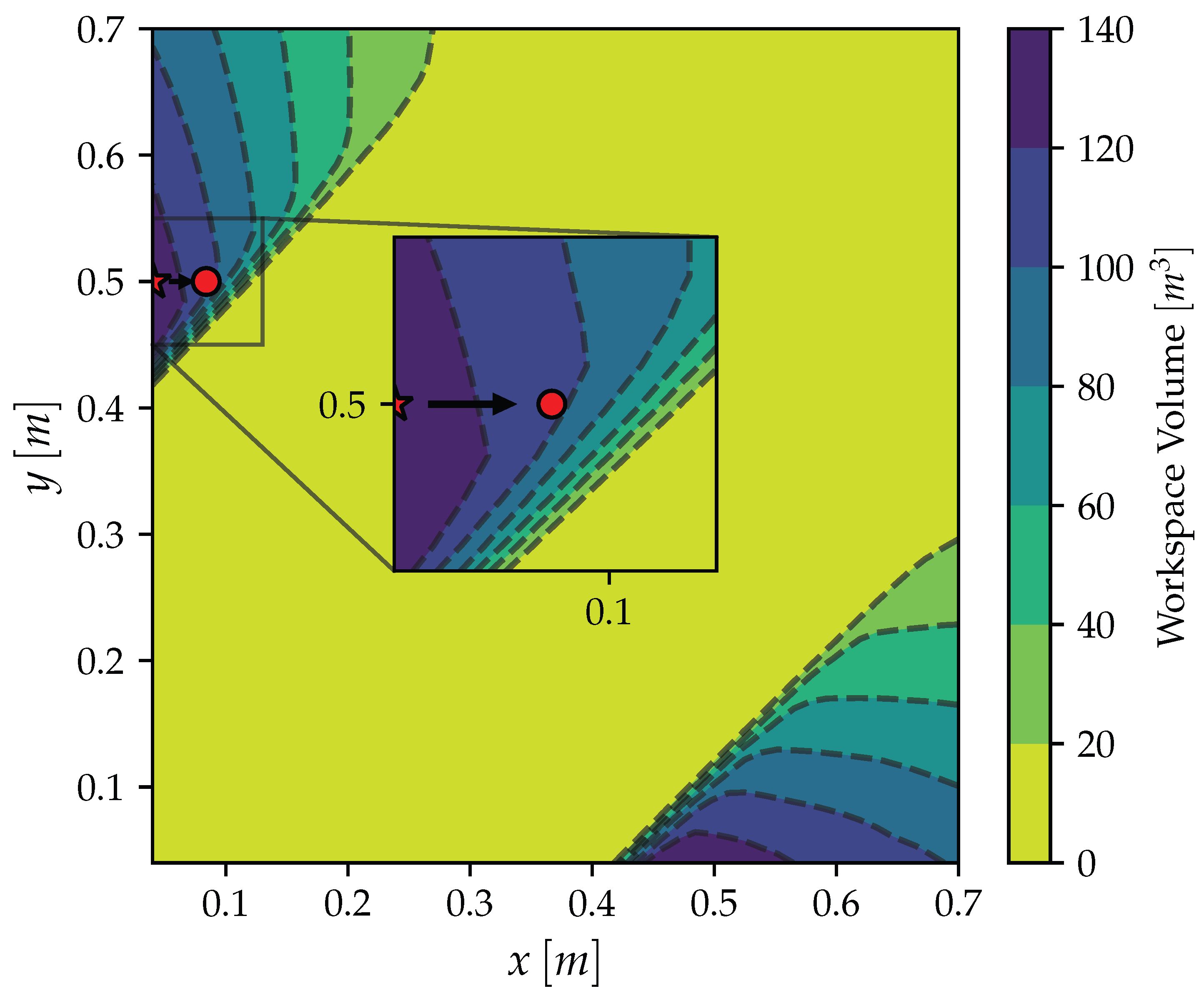
With these findings and a chosen value for the z-component of 0.5 m , the variables x = x 1 = y 2 [ 0.04   m , 0.7   m ] and y = x 2 = y 1 [ 0.04   m , 0.7   m ] in relation to the wrench-feasible, cable-cable-collision free total-orientation workspace 𝒲TO volume are visualized in Figure 7. The optimized result x = 0.04   m , y = 0.5   m , z = 0.5   m is marked with a star.
During mechanical installation of the platform, the minimum value for x was found to be 0.084 m instead of the planned 0.04 m . This is due to the actual size of the aluminum profiles in combination with the cable-platform connectors, which deviate from the dimensions established during the conceptual phase. The change is indicated by the arrow in Figure 7, and the finally realized geometry is marked with a red circle. The plot indicates that, due to the change of the x component, a 2 c m increase in the y component would be preferable to stay at the optimum; however, a change was no longer possible at that point.
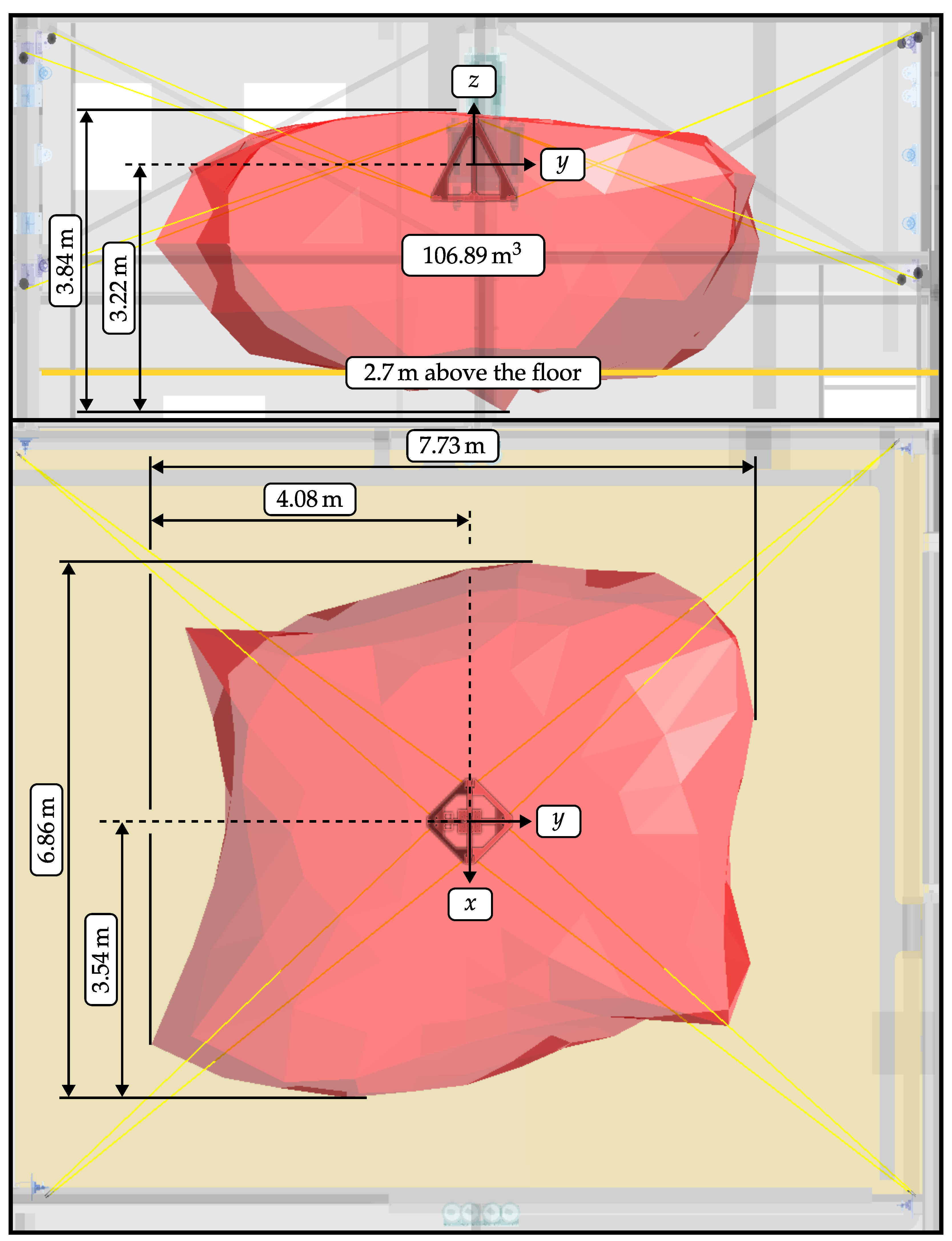
The red volume in Figure 8 visualizes the calculated total-orientation workspace 𝒲TO with a platform mass of 40 k g and a payload of 60 k g of the finally built IPAnema Safe. Furthermore, the geometry data of the IPAnema Safe are listed in Table 2.

5. Functional Safety

The required safety functions of the IPAnema Safe are listed in Section 3.2. The safety functions STO, SS1, SS2, SBC, and SBT are standard safety functions, and their implementation is therefore not further explained. For the implementation of the safety functions SLP, SLS and SLCF, a new concept is developed.
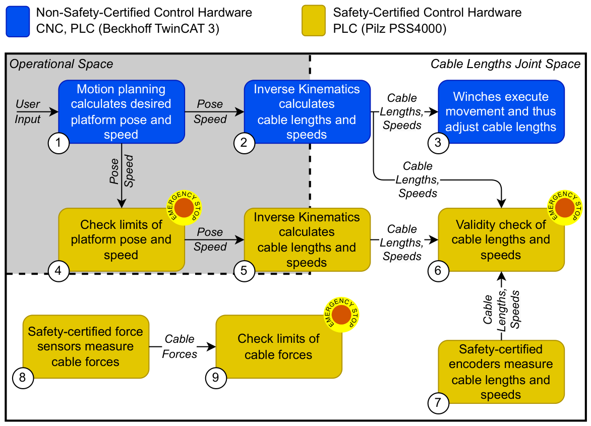
The safety concepts for the implementation of the safety functions SLP, SLS and SLCF are explained according to Figure 9. Yellow blocks represent calculations implemented within the safety-certified controller (Pilz PSS4000) or safety-certified sensors. Blue blocks represent calculations implemented within the non-safety-certified robot controller (TwinCAT 3) or non-safety-certified sensors/actuators. Blocks with an emergency stop symbol in the upper right corner can trigger an emergency stop in case the robot exceeds the safety limits. The blocks located in the area with a gray background operate on the platform pose and speed, i.e., in the operational space. The remaining blocks with a white background operate in the cable length joint space of the robot.

5.1. Safely Limited Cable Force (SLCF)

The safety function SLCF safely limits the cable forces. It is displayed in the lower left corner in Figure 9, ➇–➈. As mentioned in Section 4.1, each cable is redirected by a force measurement pulley, which measures the cable force. The force measurement sensor is safety-certified and fulfills the Performance Level e (PL e). The measured force values are transferred to the safety-certified controller, which assesses whether they are within the permissible safety limits. If one or multiple cables exceed the force limits, an emergency stop is triggered.

5.2. Safely Limited Position (SLP) and Safely Limited Speed (SLS)

Safely monitoring the position, orientation and speed of a robot’s platform or end-effector usually requires the implementation of the robot’s forward kinematics within a safety-certified controller. Thus, the end-effector position can be safely calculated from safety-certified encoder positions and speed measurements of each axis. For redundantly-constrained parallel robots, such as the IPAnema Safe, the forward kinematics is highly nonlinear and cannot be solved explicitly. It requires an iterative numerical solver, which is computationally expensive and cannot be practically implemented within a safety-certified controller.
To circumvent this issue, we propose a novel approach for monitoring the platform pose and speed of a CDPR, which only requires the computation of the simpler, explicitly solvable inverse kinematics within the safety-certified controller. Starting from the upper left corner in Figure 9, a trajectory or commanded target position is given to the motion planning block ➀. The non-safety-certified CNC executes the motion planning and transmits the desired pose and speed to the safety-certified controller and the inverse kinematics of the non-safety-certified controller. The safety-certified controller performs an initial verification to determine whether the transferred pose and speed lie within the safety limits of a predefined volume ➃. In the event that the limits are exceeded, an emergency stop is triggered. If the test is passed, both the non-safety-certified controller and the safety-certified controller calculate the inverse kinematics, i.e., transforming the Cartesian platform pose and speed to cable lengths and cable speeds ➁,➄. Finally, the resulting cable lengths and speeds of both controllers are validated by comparing them to the measurements of the safety-certified encoders ➅,➆. If the difference between the cable lengths, calculated by the inverse kinematics, and the values measured by the safety-certified encoders Δ l R 8 exceeds a certain tolerance Δ l max R , i.e., Δ l > Δ l max , an emergency stop is triggered. Similarly, if the difference between the cable speeds, calculated by the inverse kinematics, and the values measured by the safety-certified encoders Δ v c R 8 exceeds a certain tolerance Δ v c , max R , i.e., Δ v c > Δ v c , max , an emergency stop is triggered. If all verifications are passed, the commanded movement is executed by the winches ➂.
The platform’s pose and speed are indirectly safely limited by comparing the non-safety-certified and safety-certified values of the cable lengths and cable speeds. This comparison is only possible within a tolerance range Δ l max and Δ v c , max . Transforming these tolerances into the platform’s pose and speed deviations can lead to an amplification due to the kinematic structure of CDPRs. This means that a certain deviation of the cable lengths and cable speeds can result in a bigger deviation of the platform’s pose and speed, which has to be taken into account for the parameterization of Δ l max and Δ v c , max . Therefore, the following considerations are made.

5.2.1. Amplification Between Cable Lengths/Speeds Tolerances and Platform Pose/Speed Deviations

The relationship between the cable lengths l R 8 and the platform pose x R 6 of redundantly-constrained parallel robots is highly nonlinear and cannot be solved explicitly. For small deviations Δ x R 6 , Δ l R 8 , this relationship can be linearized with the structure matrix A T R 8 × 6 , which satisfies
Δ l = A T Δ x .
This equation can be inverted using the pseudo-inverse A + T R 6 × 8 of the structure matrix and split into two parts for the translational and rotational components of the pose using the notation A trans + T , A rot + T R 3 × 8 for the respective parts of the pseudo-inverse. To derive upper bounds for the translational and rotational pose deviations, the maximum vector norm · and its induced matrix norm are used. The maximum norm of a vector x is defined as the maximum absolute value of its components. Its induced matrix norm is defined as the corresponding maximum amplification factor of a matrix A
x = max i = 1 , , n x i , A = max x = 1 Ax for x R n and A R m × n .
For the readers’ convenience, we only state the estimate for the translational part, since the rotational part can be derived in the same way.
Δ x trans = A trans + T Δ l A trans + T · Δ l A trans + T Δ l max
This estimate varies for different platform poses as the structure matrix and its pseudo-inverse are dependent on the pose. To find an upper bound on the pose deviations for all platform poses in the potential workspace 𝒲P of the IPAnema Safe, the maximum of A trans + T and A rot + T is calculated using a 6-dimensional grid search within the boundaries
x 3.8   m , 3.8   m , a 20 ° , 20 ° ,
y 4.2   m , 4.2   m , b 20 ° , 20 ° ,
z 5.0   m , 1.5   m , c 10 ° , 10 ° .
This potential workspace 𝒲P of the IPAnema Safe is discretized in 17 steps for each translational direction ( x , y , z ) and in 3 steps for each rotational direction ( a , b , c ) . This discretization is chosen to be fine enough to ensure that the maximum amplification factors are not significantly underestimated, as the pseudo-inverse of the structure matrix A + T is a continuous function of the platform pose x . The resulting maximum amplification factors for the IPAnema Safe are calculated as
max x 𝒲 P A trans + T = 3.68 , max x 𝒲 P A rot + T = 7.19 rad m 1 .
Note that the translational factor is unitless as it maps from Δl to Δx, which are both measured in meters. The rotational factor has the unit rad m −1 because it maps from Δl (in meters) to platform orientation deviations (in radians).

5.2.2. Parameterization of the Safety Function Safely Limited Position (SLP)

The safety function SLP is parameterized by limiting the cable length tolerance to l max = 0.05   m . This value is empirically determined by monitoring the maximum difference between the cable lengths calculated by the non-safety-certified controller and the cable lengths measured by the safety-certified encoders running various trajectories throughout the robot’s workspace at a maximum speed of 1.4 m s −1. It is primarily influenced by the cycle time of the safety-certified controller and the transmission time of the interface between the non-safety-certified controller and the safety-certified controller. Accounting for the maximum translational amplification from Equation (12), this imposes the bound Δ x trans 0.184   m on the maximum deviation of the platform pose. Therefore, the safety function SLP is implemented by subtracting 0.2   m from the maximum allowed platform position limits for the verification within the safety-certified controller (Figure 9, ➃).
Deviations of the platform’s orientation are limited by the second amplification factor from Equation (12). This yields a maximum deviation of Δ x rot 0.3595   rad (20.59°) for the parameterized bound of the cable length tolerance Δ l max = 0.05   m . For use cases where the platform is constrained to remain at least 2.7 m above the ground, this relatively large deviation is not relevant, as people do not directly interact with the platform. For maintenance purposes, where the platform is allowed to move closer to the ground, its safety is ensured by safely limiting its translational and rotational speeds as described in the following section.

5.2.3. Parameterization of the Safety Function Safely Limited Speed (SLS)

For the safety function SLS, the speed of any point on the platform is safely limited below 0.25 m s −1. To achieve this, the same approach as for the SLP is used. The safety-certified controller monitors the tolerance between the cable speeds calculated by the non-safety-certified controller and the cable speeds measured by the safety-certified encoders Δ v c R 8 . An emergency stop is triggered if a certain tolerance Δ v c , max R , i.e., Δ v c > v c , max is exceeded. The implemented value of v c , max = 0.01   m   s −1 is chosen analogously to the cable length tolerance value. The maximum tolerance between the cable speed, calculated by the non-safety-certified controller, and the speed measured by the safety-certified encoders is empirically determined by monitoring the deviation during movements at maximum acceleration of 10 m s −2.
The resulting maximum deviations of the platform’s translational and rotational speeds are bounded by Δ trans 0.0368   m   s −1 and Δ rot 0.0719   rad   s −1. These bounds can be homogenized into a limit for the maximum speed deviation of any point on the platform. Given the platform geometry (Table 2) and the maximum size of the potential payload (Section 3), all points of the platform and potential payload lie within a 1   m radius sphere centered at the platform’s origin. Using this information the homogenized maximum speed deviation of any point on the platform can be calculated as Δ trans + 1   m   rad · rot = 0.1087   m   s −1. Adding this to the implemented speed limit of 0.1   m   s −1 yields a safety limit on the speed of any point on the platform of 0.2087   m   s −1, which fulfills the requirement to safely limit the speed below 0.25 m s −1.

5.2.4. Verification and Experimental Validation of the Safety Functions

As part of the verification process, calculations are carried out using Pilz’s PAScal software to ensure that the safety functions meet the required Performance Level e (PL e). Additionally, the software implemented on the safety-certified controller is verified through code reviews and unit testing to guarantee correct functionality.
After the installation and commissioning of the system, the different safety functions must be validated. In addition to standard tests, such as checking whether the electrical safety system correctly detects wire breaks or short circuits, the following safety tests are performed. Each test is performed multiple times at different positions and directions.
  • SLCF: To validate the SLCF safety function, both the upper and lower cable force limits are exceeded for each cable in order to ensure that the safety-certified controller detects the limit violation and initiates an emergency stop.
  • SLP: To validate the SLP safety function, two tests are carried out. First, the platform is commanded to a pose outside the safety position limits, where the resulting limit violation must be detected by the safety-certified controller and trigger an emergency stop (Figure 9, ➃). Second, the pose data transmission between the non-safety-certified controller and the safety-certified controller (Figure 9, connection between ➀ and ➃) is actively manipulated such that a constant pose is transmitted by the non-safety-certified controller. When the platform is subsequently commanded to move, the safety-certified controller must detect the incorrect pose data within the parameterized tolerance and trigger an emergency stop (Figure 9, ➅).
  • SLS: The safety function SLS is, in principle, tested with the same two tests as the SLP safety function. For the first test, the platform is commanded to move at a speed beyond the limit of 0.25 m s −1. As soon as the speed limit is exceeded, the safety-certified controller must stop the robot by an emergency stop (Figure 9, ➃). In the second test, the data transmission between the safety-certified controller and the non-safety-certified controller is actively manipulated between ➀ and ➃, Figure 9, by keeping the transmitted speed constant. As soon as the platform is commanded to move, the safety-certified controller must detect the incorrect velocity data within the parameterized tolerance and subsequently stop the robot by an emergency stop (Figure 9, ➅).
  • System performance to achieve the intended risk reduction: The system performance to achieve the intended risk reduction is measured according to DIN EN ISO 13855 Safety of machinery—Positioning of safeguards with respect to the approach of the human body [17]. Therefore, the distance traveled by the robot’s platform after an emergency stop is triggered at maximum speed in the negative z-direction is experimentally measured using a certified stopping performance device. To ensure that the platform stops above 2.7 m , the lower workspace limit in the safety-certified controller is parameterized considering a buffer of 0.3 m for the platform’s braking distance in addition to the 0.2 m due to the possible pose uncertainty (Section 5.2.2). Consequently, the braking distance measured by the certified stopping performance device must not exceed 0.3 m .
    Tests are performed at various ( x , y ) -positions (in meters): ( 0 , 0 ) , ( 2 , 2 ) , ( 2 , 2 ) , ( 2 , 2 ) , and ( 2 , 2 ) . Each test starts at z = 0   m , with the emergency stop triggered at z = 0.5   m . The tests are repeated 10 times at each ( x , y ) -position. Across all tests, the maximum braking distance is measured as 0.233 m , which is within the allocated buffer of 0.3 m and verifies that the platform remains at least 2.7 m above the floor in case of an emergency stop.

6. Conclusions

This paper presents the design process of the IPAnema Safe, a cable-driven parallel robot which is used as a simulator for training ship crew workers onshore at the Maritime Research Institute Netherlands (MARIN). Its safety functionalities satisfy the highest functional safety standards, i.e., Performance Level e (PL e), and enable it to operate above people.
The presented methodologies to find an optimized platform design and the implementation of functional safety features can be generalized and applied to other cable-driven parallel robots or parallel kinematic machines. Future research may explore further optimization of the system’s performance and the development of different platform designs to add additional use cases.

Author Contributions

Conceptualization: C.M., M.F., C.L., and J.T.S.; software, C.M., M.F., and J.T.; mechanical design, C.M., C.L., and J.T.S.; writing—original draft preparation, C.M., M.F., C.L., and J.T.; supervision, W.K., and A.P. All authors have read and agreed to the published version of the manuscript.

Funding

This research received no external funding.

Data Availability Statement

Data is contained within the article.

Conflicts of Interest

The authors declare no conflicts of interest.

References

  1. Pott, A. Cable-Driven Parallel Robots: Theory and Application; Springer: Cham, Switzerland, 2018. [Google Scholar] [CrossRef] [Scilit]
  2. Surdilovic, D.; Bernhardt, R. STRING-MAN: A New Wire Robot for Gait Rehabilitation. In Proceedings of the IEEE International Conference on Robotics and Automation (ICRA ’04), New Orleans, LA, USA, 26 April–1 May 2004; Volume 2, pp. 2031–2036. [Google Scholar] [CrossRef] [Scilit]
  3. Otis, M.J.D.; Comtois, S.; Laurendeau, D.; Gosselin, C. Human Safety Algorithms for a Parallel Cable-Driven Haptic Interface. In Proceedings of the Brain, Body and Machine, Montreal, QC, Canada, 10–13 November 2010; Springer: Berlin/Heidelberg, Germany, 2010; pp. 187–200. [Google Scholar] [CrossRef] [Scilit]
  4. Merlet, J.P. MARIONET, A Family of Modular Wire-Driven Parallel Robots. In Advances in Robot Kinematics: Motion in Man and Machine; Springer: Dordrecht, The Netherlands, 2010; pp. 53–61. [Google Scholar] [CrossRef] [Scilit]
  5. Tempel, P.; Schnelle, F.; Pott, A.; Eberhard, P. Design and Programming for Cable-Driven Parallel Robots in the German Pavilion at the EXPO 2015. Machines 2015, 3, 223–241. [Google Scholar] [CrossRef] [Scilit]
  6. Miermeister, P.; Lachele, M.; Boss, R.; Masone, C.; Schenk, C.; Tesch, J.; Kerger, M.; Teufel, H.; Pott, A.; Bulthoff, H.H. The CableRobot Simulator Large Scale Motion Platform Based on Cable Robot Technology. In Proceedings of the 2016 IEEE/RSJ International Conference on Intelligent Robots and Systems (IROS), Daejeon, Republic of Korea, 9–14 October 2016. [Google Scholar] [CrossRef] [Scilit]
  7. Maritime Research Institute Netherlands (MARIN). Integrating eXtended Reality at New MX Lab: A LEVIATHAN Amongst Simulators. 2024. Available online: https://magazine.marin.nl/marin-report-140/mx-lab (accessed on 22 October 2024).
  8. DIN EN ISO 13849-1:2023; Safety of Machinery—Safety-Related Parts of Control Systems—Part 1: General Principles for Design. International Organization for Standardization: Berlin, Germany, 2023.
  9. Bons, A. MARIN Builds Most Realistic Simulator Centre for Maritime Operations in the World. 2022. Available online: https://www.marin.nl/en/publications/marin-builds-most-realistic-simulator-centre-for-maritime-operations-in-the-world (accessed on 21 May 2026).
  10. DIN EN ISO 12100:2011-03; Safety of Machinery—General Principles for Design—Risk Assessment and Risk Reduction. Deutsches Institut für Normung: Berlin, Germany, 2011; German edition: Sicherheit von Maschinen—Allgemeine Gestaltungsleitsätze—Risikobeurteilung und Risikominderung.
  11. Pilz GmbH & Co. KG. Safety Compendium. 2017. Available online: https://www.pilz.com/mam/pilz/content/editors_mm/safety_compendium_en_2017_12_low.pdf (accessed on 16 April 2025).
  12. Martin, C.; Fabritius, M.; Lehnertz, C.; Jurašić, P.; Stoll, J.T.; Ernst, M.O.; Kraus, W.; Pott, A. IPAnema Silent: A CDPR for Spatial Hearing Experiments. In Proceedings of the International Conference on Cable-Driven Parallel Robots; Springer: Cham, Switzerland, 2023; pp. 407–418. [Google Scholar] [CrossRef] [Scilit]
  13. Deutsche Gesetzliche Unfallversicherung (DGUV). DGUV Information 215-313—Loads over Positions Where People May be Present; Deutsche Gesetzliche Unfallversicherung e.V. (DGUV): Berlin, Germany, 2020; German edition: Lasten über Personen. [Google Scholar]
  14. DIN 15020-1:1974-02; Lifting Appliances—Principles Relating to Rope Drives—Calculation and Construction. Deutsches Institut für Normung: Berlin, Germany, 1974; German edition: Hebezeuge—Grundsätze für Seiltriebe, Berechnung und Ausführung.
  15. German Social Accident Insurance (DGUV). FBHM-005—Gravity-Loaded Axes—Vertical Axes; German Social Accident Insurance (DGUV): Berlin, Germany, 2021; German edition: Schwerkraftbelastete Achsen—Vertikalachsen, Webcode: p021977. [Google Scholar]
  16. Idà, E.; Mattioni, V. Cable-Driven Parallel Robot Actuators: State of the Art and Novel Servo-Winch Concept. Actuators 2022, 11, 290. [Google Scholar] [CrossRef] [Scilit]
  17. DIN EN ISO 13855:2025-10; Safety of Machinery—Positioning of Safeguards with Respect to the Approach of the Human Body. Deutsches Institut für Normung: Berlin, Germany, 2025; German edition: Sicherheit von Maschinen—Anordnung von Schutzeinrichtungen im Hinblick auf Annäherung des menschlichen Körpers.
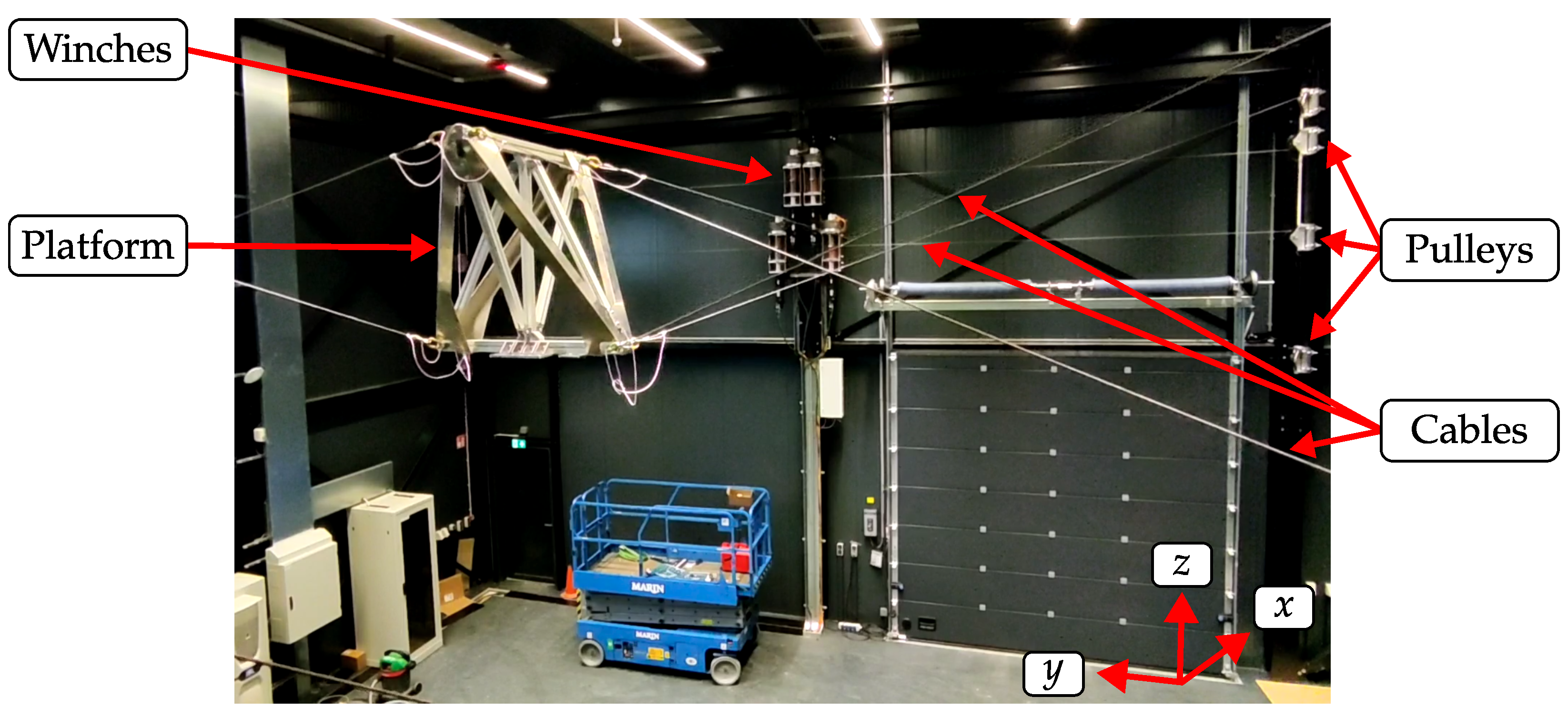
Figure 1. IPAnema Safe (https://youtu.be/vFaTntglG5g, accessed on 24 June 2026) installed at MARIN in Wageningen, The Netherlands.
Robotics 15 00124 g001
Figure 2. Use case visualization: IPAnema Safe simulates the motion of a hook dangling from a helicopter [9].
Robotics 15 00124 g002
Figure 3. Visualization of the IPAnema Safe layout.
Robotics 15 00124 g003
Figure 4. Design process of the drum of the winch.
Robotics 15 00124 g004
Figure 5. Cable securing mechanisms in case of tension loss: (a) wide pressure roller, (b) actuated wide pressure roller, (c) narrow pressure roller, (d) steel rails.
Robotics 15 00124 g005
Figure 6. Final IPAnema Safe winch design.
Robotics 15 00124 g006
Figure 7. Visualization of the volume of the total-orientation workspace in relation to the proximal anchor point variables x and y for z = 0.5   m .
Robotics 15 00124 g007
Figure 8. Total-orientation workspace 𝒲TO (advanced closed-form method [1], platform mass of 40 k g and a payload of 60 k g ).
Robotics 15 00124 g008
Figure 9. Safety concept for the safety functions: SLP, SLS, SLCF.
Robotics 15 00124 g009
Table 1. Technical data of the winches.
Nominal rotation speednnom203 min−1
Maximum torqueMmax255 N m
Maximum cable speedvmax1.4 m s−1
Maximum cable strokeΔlmax,stroke19.05 m
Drum diameterD131.7 mm
Maximum cable forceFmax3878 N
Safely limited cable forceFSLCF3350 N
Cable diameterd6 mm
Cable minimum breaking forceFmbf33.1 kN
Cable safety factorScable9.88
Number of windingsnwindings44
Table 2. Geometrical parameters of the IPAnema Safe.
Cable ia [m]b [m]
1 4.792 , 5.729 , 1.562 T 0.084 , 0.508 , 0.498 T
2 4.803 , 5.454 , 1.547 T 0.084 , 0.492 , 0.499 T
3 4.739 , 5.816 , 1.300 T 0.084 , 0.492 , 0.499 T
4 4.914 , 5.516 , 1.488 T 0.083 , 0.508 , 0.498 T
5 4.820 , 5.733 , 1.451 T 0.501 , 0.089 , 0.500 T
6 4.833 , 5.448 , 1.275 T 0.501 , 0.078 , 0.501 T
7 4.712 , 5.813 , 1.586 T 0.499 , 0.078 , 0.499 T
8 4.885 , 5.521 , 1.531 T 0.498 , 0.089 , 0.499 T
Disclaimer/Publisher’s Note: The statements, opinions and data contained in all publications are solely those of the individual author(s) and contributor(s) and not of MDPI and/or the editor(s). MDPI and/or the editor(s) disclaim responsibility for any injury to people or property resulting from any ideas, methods, instructions or products referred to in the content.