Article

An Intelligent Loading System for Standardized Mining Material Transportation Based on Multimodal Perception and Multi-Arm Collaboration

1
School of Mechanical, Electronic and Control Engineering, Beijing Jiaotong University, Beijing 100044, China
2
Huaneng Coal Technology Research Co., Ltd., Beijing 100070, China
3
Zhalainuoer Coal Industry Co., Ltd., Manzhouli 021410, China
4
Tangshan Research Institute, Beijing Jiaotong University, Tangshan 063000, China
*
Author to whom correspondence should be addressed.
Robotics 2026, 15(6), 105; https://doi.org/10.3390/robotics15060105
Submission received: 31 March 2026 / Revised: 18 May 2026 / Accepted: 22 May 2026 / Published: 27 May 2026
(This article belongs to the Section AI in Robotics)

Abstract

Currently, mining material transportation in warehouses relies heavily on manual operations, which pose safety hazards and suffer from low standardization and automation. Existing automated attempts using single-sensor perception or single-arm manipulators lack robustness and adaptability in harsh mine environments. To address these gaps, this paper proposes an intelligent loading system for standardized mining material transportation based on multimodal perception and multi-arm collaboration. First, the overall architecture of the transportation and loading system is introduced, comprising five modules: a standardized carrier platform and modular transport boxes, a box locking and spreader module, a multi-sensor recognition and positioning module, a multi-manipulator collaborative loading/unloading module, and a perception feedback and (human-controlled) overhead crane module. Next, a standardized hardware system is designed, focusing on the standardization of the separable and easily detachable carrier platform and the modularization of transport boxes, along with the locking mechanism between them, establishing the hardware foundation for the system. Subsequently, a multimodal perception data fusion and recognition positioning technology based on multiple depth cameras, UWB, and IMU is investigated to provide perceptual feedback for automated loading/unloading. Following this, a multi-manipulator collaborative control technology based on multi-agent error consensus is developed, designing a “two-master, two-slave” structure and a collaborative control algorithm to achieve automated loading/unloading of transport boxes. An information-based interactive monitoring software is then designed to monitor system perception data in real time and control the system’s operational status, ensuring safety and controllability. Finally, the feasibility and effectiveness of the system are validated through simulations and prototype experiments. This work provides a foundation for standardized transportation and storage of mining materials and outlines a practical system-level approach.

1. Introduction

Driven by the strategic goals of carbon neutrality, intelligent manufacturing, and high-quality industrial development, the coal industry is undergoing a profound transformation toward intelligent and autonomous mining systems [1,2,3]. In recent years, the integration of robotics, artificial intelligence, machine vision, and multi-sensor perception has significantly accelerated the development of smart mines and intelligent mining equipment [4,5,6]. Among the various subsystems in intelligent mines, material transportation and loading/unloading operations play a critical role in ensuring production continuity, operational safety, and transportation efficiency. Consequently, the development of autonomous and intelligent transportation systems has become a key research direction in modern coal mine engineering [7,8,9].
Coal mine transportation systems are generally classified into rail-bound and trackless categories, which are further divided into primary and auxiliary transportation systems according to operational functions [10,11,12]. Existing studies have explored intelligent transportation robots, transfer robots, and automated auxiliary transportation systems for mining environments. For example, Chen Min [13] and Xu Jinyi [14] designed transfer robots and corresponding control algorithms for small-scale mine transportation applications. Zhou Peng [15] proposed a 5G-based intelligent auxiliary transportation robot system for underground mines, while Liang Honglei et al. [16] developed an intelligent inspection robot for transportation systems operating in harsh underground environments. Rong Guoqing [17] built a patrol robot system based on TD-LTE technology, and Zhou Dehua [18] studied key technologies of a multi-agent control system for trackless coal mine transportation robots. In addition, research on autonomous perception, wireless communication, and multi-agent collaborative control has further promoted the development of intelligent transportation technologies in coal mines [19].
Despite these advances, the loading and unloading processes of mining materials still rely heavily on manual or semi-automatic operations in most mines and storage facilities. The diversity of transported materials, the complexity of underground environments, and the lack of standardized transportation carriers result in low operational efficiency, high labor intensity, and considerable safety risks. Traditional mine cars are widely adopted because of their simple structure and high reliability; however, they suffer from several limitations, including poor material classification capability, inefficient loading and unloading processes, low space utilization, and scheduling difficulties among different vehicle types. Moreover, harsh geological conditions and confined underground environments further increase the operational risks faced by workers. Therefore, achieving a fully automated and intelligent loading/unloading workflow remains a significant challenge for current mining transportation systems.
To address these issues, recent studies have introduced the concept of standardized modular transportation inspired by containerized logistics systems. Cui Tengfei et al. [20] proposed and validated a containerized auxiliary transportation mode, demonstrating its advantages in safety, economy, and transportation efficiency. Wang Wen [21] designed a transfer robot system based on standardized transport containers and hydraulic manipulators for automated loading and unloading operations. Tian Xiang [22] further developed an innovative transfer robot for rail transportation scenarios, promoting the realization of continuous, standardized, and unmanned transportation processes. Hao Mingrui [23] proposed a design for a mine wheeled material transport robot with clean power, environment perception, positioning navigation, and autonomous driving functions. These studies indicate that modularized transportation carriers combined with robotic automation provide an effective solution for improving transportation flexibility and reducing manual intervention in mining operations.
Meanwhile, advances in artificial intelligence and machine vision technologies have provided new opportunities for intelligent perception and autonomous manipulation in industrial environments. Deep learning-based perception algorithms have demonstrated remarkable performance in object detection, visual recognition, and fault diagnosis tasks [24,25,26]. In particular, the YOLO series of real-time object detection algorithms has been widely adopted in industrial robotics due to its high accuracy and fast inference speed. Furthermore, multimodal perception methods integrating depth cameras, ultra-wideband (UWB), inertial measurement units (IMUs), and visual sensors have significantly improved the robustness and reliability of positioning and environmental perception systems in complex industrial scenarios [27,28]. In parallel, multi-manipulator collaborative control techniques have enabled coordinated robotic operations in dynamic and constrained environments, providing an effective approach for automated loading and unloading tasks [29,30,31,32]. The design of specialized end-effectors for such tasks has also been explored, as demonstrated by Wang et al. [33], who developed a multi-functional robotic gripper with optimized design and deep vision-based control for automatic loading systems. For related applications in container handling, the development of twist lock technology has been systematically reviewed [34], and multi-camera-based recognition and localization methods have been studied [35]. Recent surveys have further consolidated the state of the art in autonomous robots and multi-robot navigation, covering perception, planning, and collaboration [36].
Motivated by these developments, this paper proposes an intelligent loading system for standardized mining material transportation based on multimodal perception and multi-manipulator collaboration. Inspired by automated container loading technologies in ports and logistics systems, the proposed framework introduces a standardized carrier platform and modular transport boxes to replace conventional mine cars, thereby improving transportation standardization and operational flexibility. The system integrates multimodal perception technologies, including multiple depth cameras, UWB sensors, and IMU sensors, to achieve accurate positioning and robust state estimation of transport boxes under complex operating conditions. In addition, a multi-manipulator collaborative control strategy is designed to realize autonomous loading and unloading operations, effectively reducing manual labor intensity and improving transportation efficiency.
Compared with traditional mine transportation methods, the proposed system offers several advantages. First, the modular transport boxes support classified transportation and standardized management of mining materials, improving storage and dispatch efficiency. Second, multimodal sensor fusion provides redundant perception and real-time safety monitoring capabilities, enhancing operational reliability in harsh mining environments. Third, the collaborative robotic loading/unloading mechanism significantly reduces operation time and minimizes human exposure to hazardous conditions. Furthermore, the standardized transportation units are compatible with multiple transportation platforms, including underground rail systems, trucks, and trains, enabling flexible deployment across various mining scenarios.
The main contributions of this paper are summarized as follows:
  • A standardized modular transportation architecture for intelligent mining material transportation is proposed, improving transportation flexibility and standardization.
  • A multimodal perception framework integrating depth vision, UWB, and IMU sensors is developed for robust transport box localization and state estimation.
  • A multi-manipulator collaborative loading/unloading strategy is designed to realize autonomous and efficient transportation operations.
  • An intelligent loading system prototype is implemented and validated, demonstrating the feasibility and effectiveness of the proposed framework in mining transportation scenarios.

2. Nomenclature

The following variables and symbols in Table 1 are used in the mathematical formulations throughout this paper.

3. System Architecture for Transportation and Loading

3.1. System Components

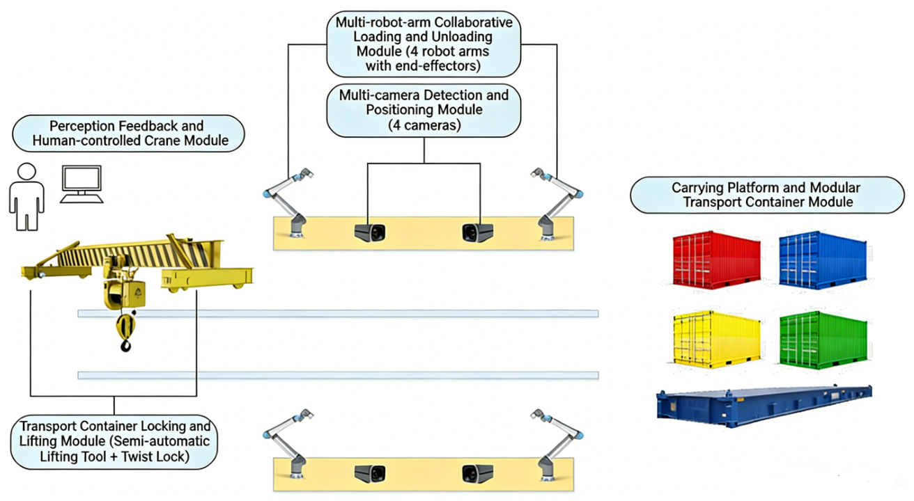
As shown in Figure 1, the material standardized transportation and loading system consists of five modules: (1) standardized carrier platform and modular transport boxes, (2) transport box locking and spreader module, (3) multi-sensor recognition and positioning module, (4) multi-manipulator collaborative loading/unloading module, and (5) perception feedback and (human-controlled) overhead crane module.
  • Standardized Carrier Platform and Modular Transport Boxes Module: The universal standardized carrier platform can serve as a mine flatbed car or be equipped with different modular transport boxes, functioning as various types of mine cars (fixed-body, dump, side-dump, bottom-dump, materials car). Modular transport boxes can carry different material types, meeting diverse transport needs in coal mine production. Inspired by container design [34], the carrier platform and transport boxes utilize clever mechanical structures enabling flexible loading and unloading of boxes.
  • Transport Box Locking and Spreader Module: Similar to containers, modular transport boxes can be locked onto the flatbed to create various mine cars or stacked and locked together to improve warehouse space utilization and above-ground transport efficiency. A universal spreader module adapts to different modular transport boxes, automating attachment and detachment, while accounting for sway during movement. The locking module operates fully automatically, accurately locking/unlocking boxes to the carrier platform or to each other.
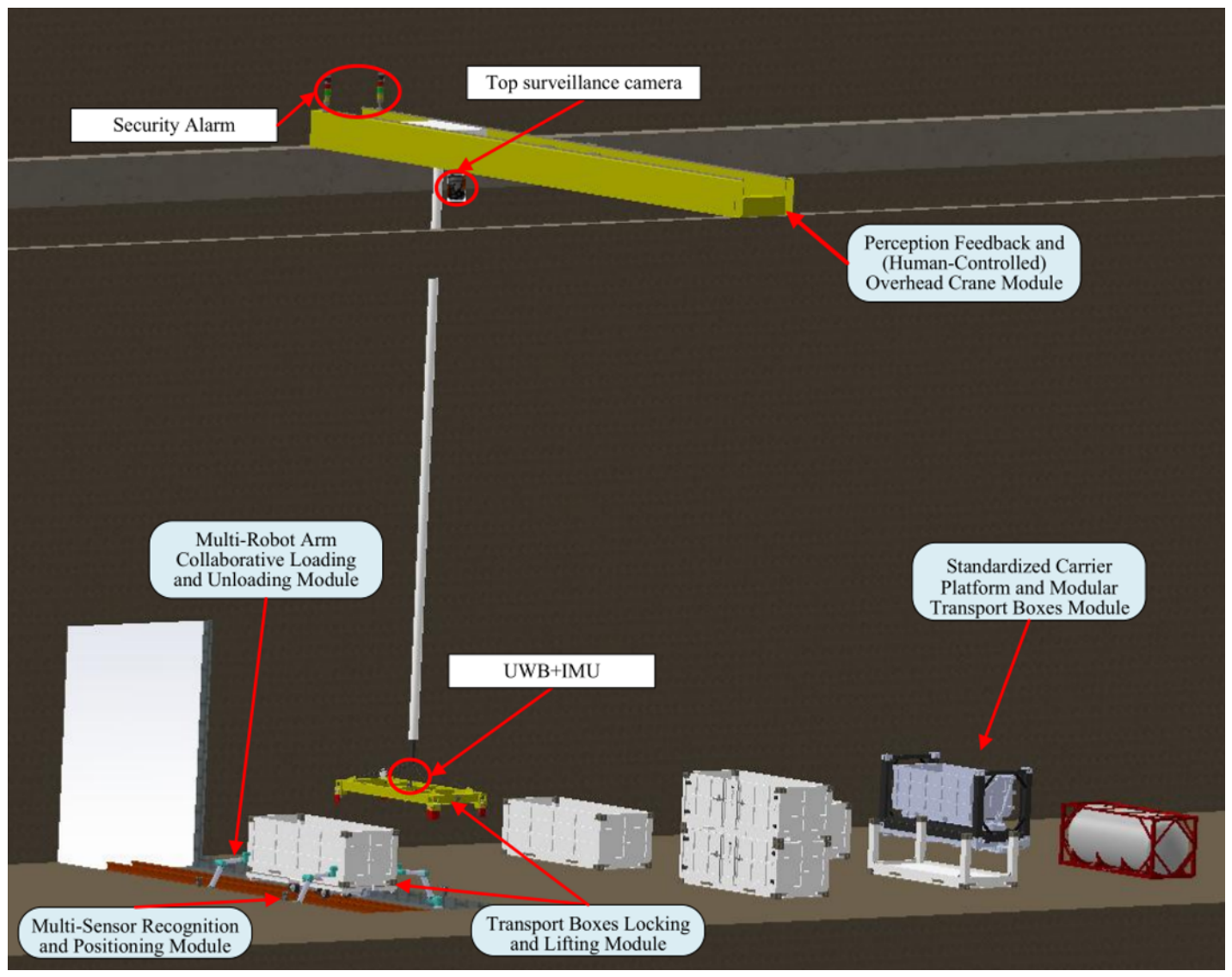
  • Multi-Sensor Recognition and Positioning Module: This module consists of sensors such as UWB, IMU, and multiple depth cameras. UWB and IMU capture the 3D position and attitude of the spreader and transport box. Multiple depth cameras are used to develop intelligent perception algorithms for recognizing the poses of the transport box and carrier platform, calculating their relative position. These measurements provide reference inputs for the multi-manipulator module and support real-time data exchange. Additionally, monitoring cameras on the overhead crane detect personnel intrusion and issue hazard warnings.
  • Multi-Manipulator Collaborative Loading/Unloading Module: Based on perceptual feedback from the multi-sensor module, this module simulates operator loading/unloading actions. It uses collaborative control of multiple manipulators to achieve precise loading/unloading. It processes real-time pose data, automatically corrects the box’s pose, plans paths in real time, and includes obstacle avoidance. The module has fault tolerance; if one or more manipulators fail, the remaining ones can still complete the task. It can build reinforcement learning models using historical data to optimize motion trajectories. The manipulators operate safely and reliably, supporting fully automatic or manual modes, with emergency stop and manual control interfaces.
  • Perception Feedback and (Human-Controlled) Overhead Crane Module: This module monitors and controls the system, displaying all perception data (from the multi-sensor module) and controlling all actuators (manipulators, crane). The overhead crane can be automated or operate in a human-in-the-loop (HITL) mode, with the latter discussed below. It features an HMI (Human–Machine Interface) software displaying live feeds from crane-top and depth cameras, box pose data, and current loading status. In HITL mode, the software guides the crane operator for horizontal, longitudinal, and height control, providing manual interfaces and emergency stop. When the crane positions the box above the carrier platform within the manipulators’ workspace, it prompts no further operator action needed. After the manipulators correct the box’s pose, it signals the operator to lower it. The module monitors progress, detects people in the work area, provides alerts, and includes emergency stop and manual operation buttons for the entire system.

3.2. Overall Architecture

The overall system architecture is shown in Figure 2. The standardized carrier platform and modular transport boxes are combined for various transport tasks. The multi-sensor recognition and positioning module operates reliably under extreme temperatures, providing real-time pose data to the control system. The multi-manipulator collaborative loading/unloading module automates the process, improving efficiency and reducing labor costs. The transport box locking and spreader module automates attachment/detachment between spreader and box, locking/unlocking between boxes, and uses the manipulators to lock/unlock the box to the carrier platform via manually operable twist locks, enhancing safety. The perception feedback and (human-controlled) overhead crane module processes sensor data, displays progress, guides the crane operator, monitors the entire system, and issues hazard warnings.

3.3. Operational Process

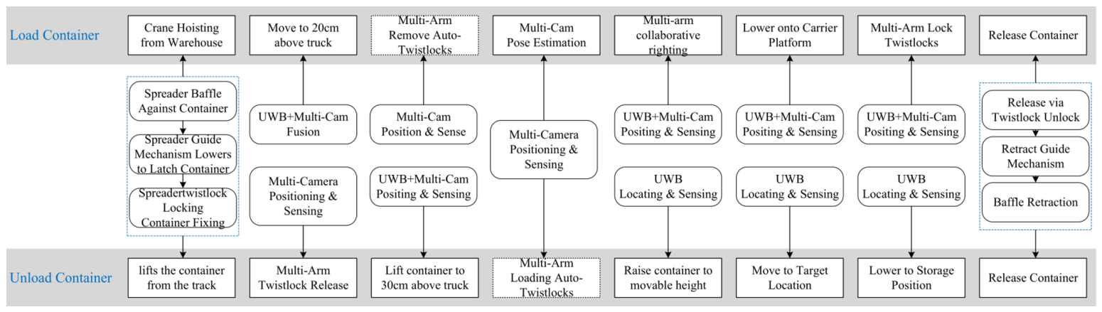
The system operation flow is shown in Figure 3, divided into loading and unloading processes. In HITL mode, the crane requires a human operator, reducing on-site personnel to one. For effective human–machine interaction, the entire process is sensor-monitored. After each step, the monitoring system prompts the operator to proceed or indicates errors. The crane operator must be trained and understand the monitoring system.

3.3.1. Loading Process

When transporting materials from the warehouse to the outside, the human-controlled crane moves the box over the carrier platform. The multi-manipulator module uses data from the multi-sensor fusion perception. When the box is about 25 cm above the platform, the UWB and multiple depth cameras transmit its position to the manipulator and crane modules; the operator stops the crane. Manipulators, guided by depth camera vision, remove the automatic twist locks from the box bottom and place them aside. The IMU and depth cameras then send the box’s pose to the control system to check alignment. Manipulators correct misalignment-based on calculated errors. Finally, the manipulators lock the manual twist locks, guided by vision recognition, completing loading.

3.3.2. Unloading Process

Unloading is the reverse. After the carrier platform arrives, manipulators unlock the manual twist locks guided by vision. The crane lifts the box. When it is about 30 cm above the platform, UWB and depth cameras transmit position data; the operator stops the crane. Manipulators pick up automatic twist locks and, guided by vision, attach them to the box bottom. The crane then moves the box to the designated location.

3.4. Multi-Module Collaborative Working Mechanism

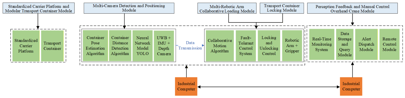
This system establishes a collaborative mechanism centered on an industrial computer, integrating multimodal perception, human–machine collaborative decision-making, and multi-arm cooperative execution. As shown in Figure 4, modules interact closely through information and control flows, forming a “perception-decision-execution” loop under multimodal information fusion and Human-in-the-Loop (HITL) mode.
The loading process exemplifies this synergy, starting with global positioning and human-controlled lifting, ending with fine pose adjustment and mechanical locking.
First, global positioning (UWB) and HITL initiate the workflow. After the carrier platform is positioned, UWB base stations track the box’s tag, displaying its coordinates on the monitoring software. The crane operator decides and moves the crane, attaching the spreader to the box. Here, UWB provides global perception, while the human operator replaces complex automatic recognition and grasping for initial movement and coarse positioning in large, unstructured environments.
Next, the system enters high-precision automated operation driven by multimodal perception. When the operator positions the box within the manipulator workspace (a predetermined height above the platform), control partially transfers to the industrial computer. Multiple depth cameras scan the box and platform twist locks for high-precision relative pose; IMU monitors box sway. The industrial computer fuses this data, generating precise pose adjustment commands. These are sent via TCP/IP to the four manipulator controllers. Using the multi-agent error consensus algorithm and master–slave control strategy (detailed in Section 5), the manipulator cluster performs synchronized box alignment. The system then commands the manipulators to perform fine operations, such as removing automatic twist locks and further adjusting alignment to ensure precise seating of the corner castings onto the platform twist locks. At this stage, the “multi-sensor recognition and positioning module” and the “multi-manipulator collaborative loading/unloading module” form a precise, efficient autonomous execution loop.
Finally, the system uses HMI to complete the final operation. After precise alignment, the industrial computer instructs the operator (via voice or display) to lower the box. After the operator lowers it onto the platform, the manipulators lock the manual twist locks, securing the box. The HMI in the “perception feedback and (human-controlled) overhead crane module” thus seamlessly links automation with manual operation.
Unloading follows the reverse process, adhering to the collaborative pattern: “manual lifting/unlocking → machine vision positioning and manipulator unlocking → manual removal.”

4. Standardized Hardware System

The mechanical components comprise two main parts, both designed with standardization and modularity: the standardized carrier platform and modular transport boxes module, and the transport box locking and spreader module.
The warehouse already has rail transport capabilities. Based on this, a carrier platform suitable for rail transport is designed for at least a 10-ton load capacity while minimizing material use. Due to material diversity, efficient transport requires standardized boxes for classified materials; thus, the carrier platform must also be standardized. Existing platforms lack box fixation and separation features. Therefore, manually operable twist locks are designed at the four corners, which, by turning a handle, lock the box onto the platform.

4.1. Standardized Carrier Platform

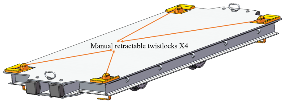
The carrier platform (Figure 5) is designed to transport various boxes.
Its standardization is based on the national standard MPC13-6 mine flatbed car [37], with a load capacity exceeding 10 tons. To enable box fixation, manually operable twist locks are welded onto the frame at the four corners, with a length spacing of 2658 mm and width spacing of 1138 mm. The twist lock consists of a bracket and a lock head. The bracket is welded to the frame. When the box corner casting aligns with the bracket hole, the handle raises the lock head through the casting, then rotates 90°, locking the head against the casting. The reverse operation unlocks. Finite element analysis confirms a load capacity over 15 tons.

4.2. Modular Transport Boxes

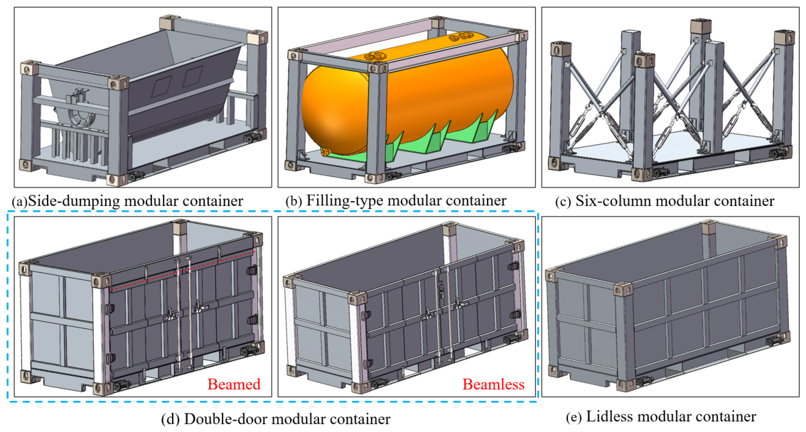
Given the diversity of materials, five types of modular transport boxes (Figure 6) are designed based on material type, shape, size, and weight, as listed in Table 2.
The double-door box has two versions: with or without a beam. The beamed version allows lock installation for security but may hinder loading/unloading of large items; the beamless version facilitates easier loading/unloading.
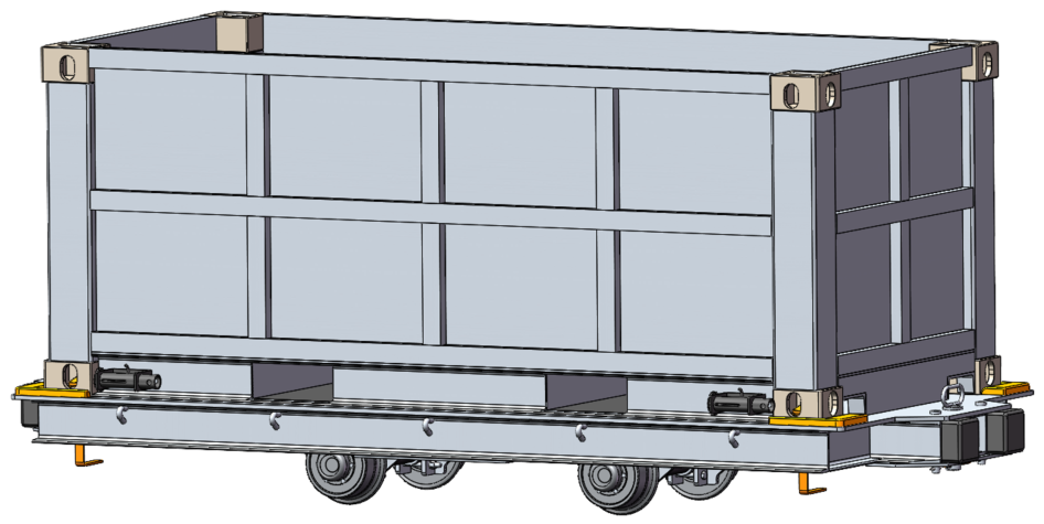
The open-top box was prototyped first and used in subsequent experiments.
Designed referencing container and mine car structures, the open-top box consists of corner posts, corner castings, side panels, bottom plate, bottom side rails, and bottom cross members (Figure 7). It can transport small bulk or oversized materials and, combined with the carrier platform, serves as a fixed-body mine car.
Table 3 lists the key mechanical specifications of the standardized carrier platform and modular transport box.

5. Multimodal Perception and Positioning System

5.1. Multi-Sensor Configuration and Layout

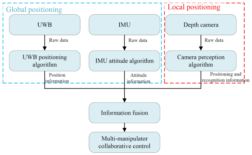
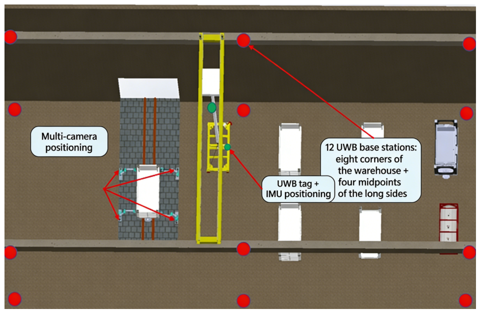
The system’s perception accuracy and robustness rely on the collaboration of heterogeneous sensors (Figure 8). UWB provides global absolute coordinates with lower accuracy, IMU provides high-frequency attitude updates with drift, and vision provides high-precision relative pose but is susceptible to occlusion and lighting. Information fusion combines their strengths into a “global coarse positioning—local fine perception—real-time attitude tracking” solution.
Multiple depth cameras recognize the box’s pose relative to the platform. UWB locates the box’s 3D position in the warehouse, and depth cameras perceive its 3D attitude. Redundancy between the sensors improves safety, and Kalman filtering enhances accuracy. Their layout is shown in Figure 9.

5.2. Global Localization and Attitude Perception

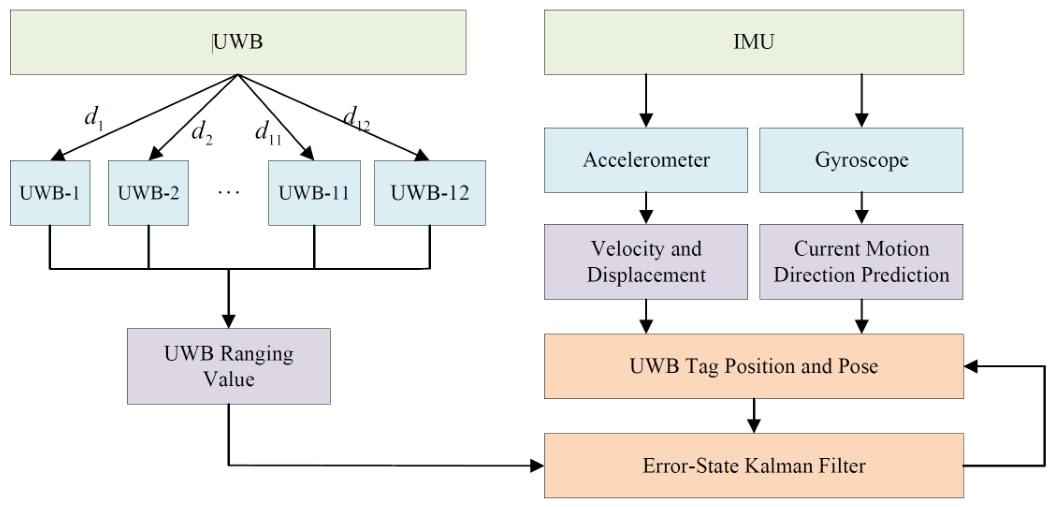
For coarse positioning and dynamic attitude tracking in the large warehouse space, this unit combines UWB and IMU. Twelve UWB base stations are installed on the warehouse ceiling. A UWB tag with an integrated IMU on the spreader provides real-time 3D coordinates (X, Y, Z) and high-frequency attitude angles (pitch, roll, yaw). The fusion principle is shown in Figure 10. This overcomes the limitations of vision sensors (occlusion, limited range) in macro-scale environments, providing visual guidance for the crane operator to efficiently and accurately transport the box to the target area.
During box transfer, its world coordinates and relative position to the platform are needed. UWB Time Difference of Arrival (TDoA) is used. With known signal speed and base station positions, the tag sends signals. Receiving base stations record arrival times. A positioning engine calculates time differences to determine distances between the tag and base stations. Solving these distance equations yields the tag’s coordinates.
Assuming the i-th base station position is ( x i , y i , z i ) , the tag position is ( x t a g , y t a g , z t a g ) , signal arrival times are t 1 , t 2 , , t 12 , and signal speed is c, we get:
( x t a g x i ) 2 + ( y t a g y i ) 2 + ( z t a g z i ) 2 = c ( t i t 0 )
where c = 3 × 10 8 m / s is the speed of light, t i are raw timestamps recorded by base stations (hardware delays pre-calibrated and subtracted), t 0 is the unknown emission time, and all distances are in meters. Time differences are in seconds. The hyperbolic equation for the distance difference between base stations i and j is:
( x t a g x i ) 2 + ( y t a g y i ) 2 + ( z t a g z i ) 2 ( x t a g x j ) 2 + ( y t a g y j ) 2 + ( z t a g z j ) 2 = c ( t i t j )
Solving these equations yields ( x t a g , y t a g , z t a g ) . Placing the tag on the spreader allows the system to guide the crane operator.
As shown in Figure 10, the IMU provides high-rate acceleration and angular velocity measurements for short-term pose estimation, while UWB absolute position updates correct accumulated IMU drift. An Error State Kalman Filter (ESKF) manages nominal and error states, suppressing IMU bias drift and handling UWB signal jumps, outputting continuous 6-DOF pose estimates at 1 kHz with accuracy better than 10 cm.
To validate the claimed <10 cm accuracy at 1 kHz, a ground-truth trajectory was obtained using a Leica laser tracker (accuracy ± 0.1 mm). The UWB tag and IMU were mounted on the spreader, which was moved along a predefined 3D path (10 m × 5 m × 2 m). The ESKF-estimated positions were compared to ground truth at 1 kHz. Over 10 runs, the root-mean-square error (RMSE) was 6.2 cm (max 9.8 cm) for positions, and 1 . 2 (max 2 . 1 ) for orientation. Non-line-of-sight (NLOS) conditions were simulated by placing a metal plate between two base stations—RMSE increased to 14.5 cm, triggering a warning in the HMI. No calibration was performed online; offline calibration using 100 static points took 5 min.
It is important to note that while UWB/IMU provides sufficient accuracy for global coarse positioning (within 10 cm), it does not meet the millimeter-level precision required for twist lock manipulation, which is instead handled by the vision-based subsystem described in Section 5.3.

5.3. Local Visual Recognition

Machine vision is widely used in industry. It involves image acquisition, preprocessing, processing, and output for subsequent actions. This system applies object detection and positioning based on machine vision for motion control [35].
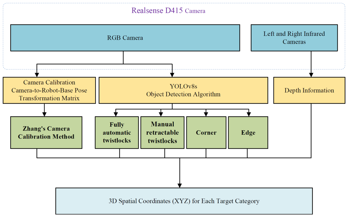
During box transfer, the system uses UWB/IMU for macro pose. When the box enters the manipulator workspace, the perception task switches to millimeter-level precision, where UWB/IMU accuracy is insufficient. A vision-based scheme using multiple depth cameras is employed. Four depth cameras, each fixed to a manipulator base and calibrated (hand–eye calibration) to its coordinate system, are used. The system uses a YOLOv8 deep learning model to detect and locate key features (corner castings, twist locks), extract pixel coordinates, fuse depth data, and transform coordinates to obtain precise 3D positions in the manipulator’s base frame (Figure 11).
A dataset of 5000 annotated images was collected from the prototype warehouse under varying lighting conditions (100–500 lux) and with controlled dust injection (0–50 mg/m3). Images were split into training (70%), validation (15%), and test (15%). Training was performed on an NVIDIA RTX 4090 GPU (24 GB) using PyTorch 2.0.1 with CUDA 11.7. The hyperparameters were set as follows: batch size of 16, initial learning rate of 0.01, SGD optimizer with momentum 0.937, 300 epochs, and input image size of 640 × 640 pixels. Data augmentation included random HSV shifts, horizontal flip, and mosaic (disabled for the last 100 epochs). Bounding boxes were labeled for five classes: corner_casting, manual_lock_red, manual_lock_black, auto_lock, and platform_edge. The YOLOv8m model was trained for 200 epochs. On the test set, the mean average precision (mAP@0.5) was 0.92, with per-class precision/recall: corner_casting (0.94/0.91), manual_lock_red (0.89/0.86), manual_lock_black (0.79/0.74), auto_lock (0.93/0.90), platform_edge (0.96/0.94). Under heavy dust (50 mg/m3) or extreme low light (100 lux), manual_lock_black recall dropped to 0.52, which motivated the use of platform edge features as a fallback.
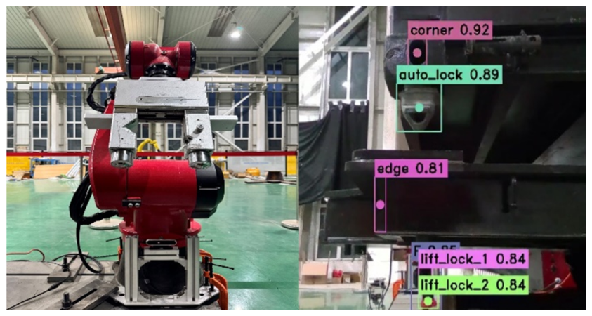
After camera calibration, the YOLOv8 algorithm (Figure 12) is used for differentiated visual recognition strategies for key components:
  • Box Corner Castings: The center area of the corner casting is hollow, causing depth data gaps. Direct center coordinate acquisition is inaccurate. Thus, a geometric center estimation method based on the 2D detection box is used. Let the image pixel coordinate system have origin at the top-left corner, u-axis rightward, v-axis downward. The YOLO detection box B i is defined by its top-left and bottom-right corners. The bounding-box center ( u c , v c ) approximates the corner casting’s projection under the assumption that the casting’s visible face is approximately fronto-parallel and symmetric. For oblique views or partial occlusion, this approximation introduces <2 pixel error, acceptable given the subsequent depth search. For a detection box B i , its four vertices are considered key feature points P 1 , P 2 , P 3 , P 4 , where
    P k = ( u k , v k ) , k = 1 , 2 , 3 , 4
    The pixel coordinates of the corner center ( u c , v c ) are:
    u c = 1 4 k = 1 4 u k
    v c = 1 4 k = 1 4 v k
  • Manually Operable Twist Locks: The recognition strategy depends on the operation phase. For loading, the red handle (lift_lock_2) is targeted; for unloading, the black handle (lift_lock_1) is targeted. The lock can have two orientations (front/back during loading, left/right during unloading), so the YOLO model must subclassify orientations for accurate feature acquisition and 3D coordinate calculation.
    During unloading, vision recognition of the black handle can be unreliable due to environmental factors, leading to feature loss. Similarly, black handle recognition can fail during loading. Feature distinction improves robustness.
    Let Ω be a rectangular search window of size W × H (pixels) centered at the bounding-box center ( u c , v c ) , clipped to image boundaries. For our setup, W = 40 , H = 25 . Instead of raw minimum, we use the 5th percentile of depth values within Ω after removing flying pixels (depth gradient > 0.2 of median). The selected pixel ( u * , v * ) is then back-projected using camera intrinsic matrix K and extrinsics T camera manipulator .
    ( u * , v * ) = arg min ( u , v ) Ω D ( u , v )
    where D ( u , v ) is the depth value. Its 3D coordinates are then back-projected using camera calibration parameters.
  • Automatic Twist Locks: For automatic locks, the strategy uses the center of the YOLO detection box (named ‘auto_lock’) directly mapped to 3D space. This is based on analysis of multi-view observations: the lock’s appearance is consistent for camera pairs (1,3) and (2,4) but differs between these groups. Relying on specific contours would require complex heterogeneous models. The structure is approximately centrally symmetric within the detection box, making the geometric center a stable attribute, avoiding interference from surface irregularities.
  • Carrier Platform Edge Features: During loading/unloading of manual twist locks, factors like lighting changes, dust, and background clutter can reduce recognition confidence (below 50%) for the colored handles. To enhance robustness, the platform’s edge dimensions (‘edge’) are used as key recognition features. The spatial relationship between the platform edge and the manual twist locks is constant, ensuring reliable recognition.

6. Multi-Manipulator Collaborative Control System

When placing the box onto the carrier platform, automatic twist locks must be removed from the box bottom, the box corner castings must align with the manual twist lock heads, and then the manual locks are fastened. When lifting the box, the process reverses. Swaying of the suspended box can cause misalignment. Traditional methods rely on manual stabilization. Applying multi-manipulator systems to this complex and hazardous task is a viable solution to reduce manpower and improve automation. This paper uses four manipulators to lock all four corner castings and designs a collaborative control method.
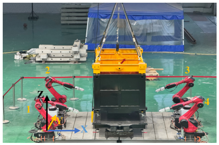
The four manipulators are numbered, and the collaborative tasks are defined relative to the world coordinate system, as shown in Figure 13.

6.1. Multi-Manipulator Collaborative Alignment Control

For the collaborative alignment task, a “two-master, two-slave” control strategy is proposed. The master arms generate an optimal pushing path based on a box trajectory prediction algorithm, while the slave arms use an adaptive step-size control algorithm for synchronized following. A key innovation is an efficient master arm decision mechanism based solely on visual observation differences. This mechanism uses relative pose information from the vision system for real-time, physically intuitive decisions, reducing hardware and modeling complexity.

6.1.1. Master Arm Multi-Stage Adaptive Normal Push Algorithm

Let P c n w = ( x c n , y c n , z c n ) T be the world coordinates ( W ) of the corner casting detected by the n-th vision sensor, obtained via hand–eye calibration and coordinate transformation. A variable Γ quantifies the yaw (rotational) deviation of the box in the horizontal plane:
Γ = ( y c 1 w y c 3 w ) ( x c 2 w x c 4 w )
Γ > 0 indicates clockwise rotation (master group: manipulators 1 and 3), Γ < 0 indicates counter-clockwise rotation (master group: manipulators 2 and 4). Corners 1–4 clockwise from front–left. Γ derived from rotation matrix. If Γ = 0 , no master group is assigned (all arms follow position setpoints).
The role assignment strategy is:
M = { 1 , 3 } , if Γ > 0 { 2 , 4 } , if Γ < 0 S = { 1 , 2 , 3 , 4 } M
where M is the master arm set, and S is the slave arm set. The master group generates a force couple to counteract the estimated rotation.
Observing the crane–box system, the box’s free swing trajectory approximates an arc with radius R related to the rope length L. The multi-stage adaptive normal push algorithm plans a conforming push trajectory to minimize impact momentum.
The continuous trajectory is discretized into a sequence of K key waypoints Q :
Q = { q 1 , q 2 , , q K }
Each waypoint q i = ( p i , R i ) includes a position vector p i and a rotation matrix R i , defining the progressive push posture.
To optimize empty travel time, the algorithm does not always start from q 1 . The decision logic uses position error along the X-axis. When a rotational deviation occurs ( Γ > 0 , master group { 2 , 4 } ), corner castings 2 and 4 might be at the near side or out of the camera’s field of view, risking data loss or noise. A robust decision strategy selects a consistently visible representative corner (corner 1) as a benchmark, based on the kinematics of rotation around the crane’s center.
Let x c r W be the X-coordinate of the chosen robust benchmark corner c r , and x c r target be its target X-coordinate. The effective position deviation Δ x eff is:
Δ x eff = x c r target x c r W
A predefined mapping function maps Δ x eff to a push stage index:
stage_index = min 5 , max 1 , | Δ x eff | / 8
where Δ x eff is in mm. The master arms execute pushes based on the current Δ x eff . The target X-coordinate x c r target is the X-coordinate of corner c r when the box is perfectly seated on the platform, obtained from CAD model.

6.1.2. Slave Arm Adaptive Tracking Algorithm

While master arms push along the planned trajectory, slave arms provide support and following to ensure stability. Their control aims to quickly and stably move to a target area (a visible corner casting) specified by the depth camera.
To balance speed and accuracy, slave arms use an adaptive step size strategy based on the tracking error.
Let p current slave R 3 be the slave arm end-effector’s world coordinates, and x corner W be the X-coordinate of the target corner. The X-direction tracking error δ x is:
δ x = | x corner W p current , x slave |
The step size S ( δ x ) is a piecewise function:
S ( δ x ) = s max , if δ x > τ max s min + ( s max s min ) · δ x τ min τ max τ min , if τ min δ x τ max s min , if 0 < δ x < τ min 0 , otherwise
where τ max and τ min are distance thresholds, and s max , s min are max/min step sizes. s max is limited by system dynamics to avoid excessive impact force upon contact. s min balances final precision and response speed. Linear interpolation provides smooth transition in the intermediate region. For our implementation, τ max = 5 mm, τ min = 30 mm, s max = 2 mm/step, s min = 10 mm/step.
Based on Equations (7)–(11), the complete pseudocode algorithm of multi-stage adaptive normal push for master arms is shown in Algorithm 1.  
Algorithm 1: Multi-stage adaptive normal push for master arms
Robotics 15 00105 i001

6.2. Multi-Manipulator Collaborative Consensus Control

Building on the master–slave architecture, a multi-agent consensus control method is proposed for tasks like loading/unloading twist locks. This algorithm emphasizes coordination (system error consensus) while maintaining individual tracking accuracy [38].
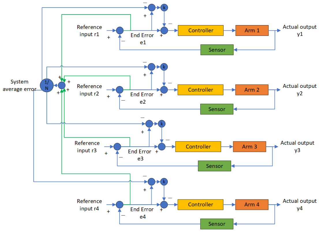
Let the pose error for manipulator i be represented as a 6D vector e i = [ p i error ; θ i error ] , where p i error = p i des p i actual (position error in meters) and θ i error is the axis-angle representation of orientation error (radians). As shown in Figure 14, let r i and y i be the desired and actual end-effector poses for the i-th manipulator ( i = 1 , 2 , 3 , 4 ). The individual error e i is:
e i = r i y i
The system average error e is:
e = 1 N i = 1 N e i , N = 4
To incorporate system consistency, a consensus error term e c , i is introduced:
e c , i = e e i
The final control input u i is a weighted sum of the individual error and the consensus error:
u i = K p e i + K c e c , i
where K p and K c are proportional and consensus gains, respectively. This can be rewritten as:
u i = ( K p K c ) e i + K c e
By adjusting K p and K c , a balance between individual tracking accuracy and system coordination is achieved. For our implementation, K p = diag ( 2.5 , 2.5 , 2.5 , 1.2 , 1.2 , 1.2 ) , K c = diag ( 1.2 , 1.2 , 1.2 , 0.5 , 0.5 , 0.5 ) . The multi-agent consensus control law (Equation (18)) is asymptotically stable under zero contact force and bounded perception noise, as the error dynamics reduce to a linear system with eigenvalues determined by ( K p K c ) and K c . For the four-arm configuration, the coupling matrix is symmetric and positive definite when K p > K c > 0 . Sensitivity analysis showed that varying K p and K c by ± 20 % changed alignment time by less than 15 % , with no stability loss.
Based on Equations (14)–(18), the complete pseudocode algorithm of multi-agent error consensus control for four manipulators is shown in Algorithm 2.
Algorithm 2: Multi-agent consensus control for four manipulators
Robotics 15 00105 i002

6.3. System Control Architecture

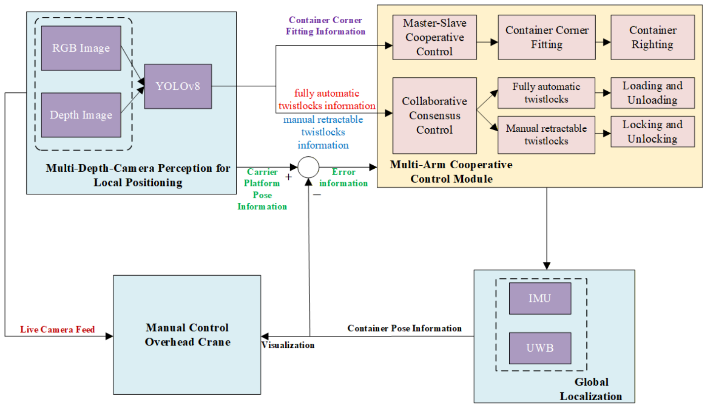
Integrating the multimodal perception and multi-manipulator control forms the overall control architecture, shown in Figure 15. All modules are integrated into a control flowchart. Visualized box pose data from IMU/UWB and real-time status from depth cameras are fed to the HITL crane module. The operator controls the crane accordingly. The error between box pose and platform pose is calculated and sent to the multi-manipulator control module. The internal controller uses the consensus algorithm to generate control signals for the manipulators, which execute the alignment. New pose data from IMU/UWB is fed back, iteratively adjusting until alignment is achieved. Additionally, the depth camera module recognizes the platform’s manual twist locks, automatic twist locks, and box corner castings, guiding the manipulators for locking/unlocking operations.
In the HITL mode, the crane operator controls the crane to lift the box. Sensor data is displayed on the operator’s screen, showing real-time box pose. The operator moves the box to the predetermined location and stops it. The manipulators then collaboratively align the box. The operator then slowly lowers the box onto the platform, with manipulators maintaining its stable pose.

7. System Integration and Experimental Testing

To validate the feasibility and effectiveness of the proposed system and methods, a prototype system was built for experimental verification.

7.1. Prototype Experiment

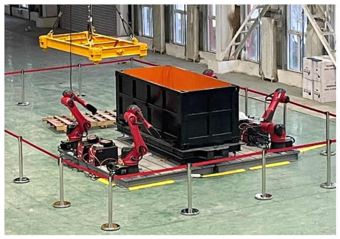
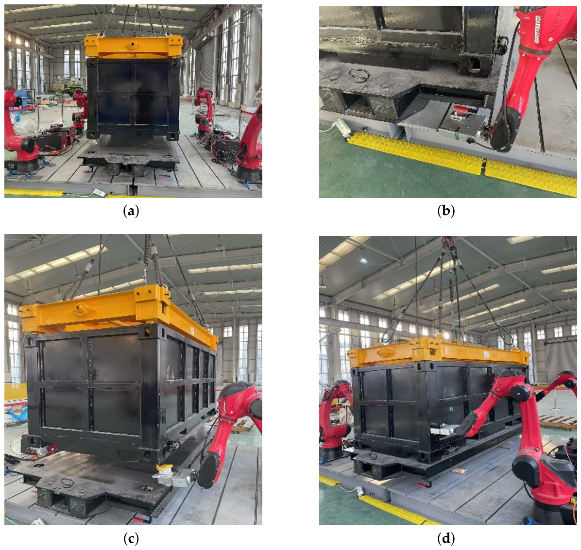
The open-top transport box and carrier platform were fabricated, and the complete intelligent loading system was assembled, as shown in Figure 16. Prototype experiments were then conducted for loading the open-top box onto the carrier platform, as shown in Figure 17.
The multi-manipulator loading workflow consists of five main stages: moving the box into the workspace, collaborative alignment, grasping automatic twist locks, final collaborative alignment and precise positioning onto the platform, and loading manual twist locks. The unloading workflow similarly comprises five stages: unloading manual twist locks, lifting the box (1.5 m above platform), real-time alignment adjustment, grasping automatic twist locks, and finally moving and placing the box in a designated area.
In these experiments, crane operations (moving boxes into/out of the workspace, lifting to/from 1.5 m height) were performed manually by the crane operator. All other steps were automated.

7.2. Complete Loading/Unloading Process

To ensure statistical reliability, the complete loading/unloading process was repeated 100 times under identical conditions (same operator, same environmental lighting, no dust injection). For each trial, the following sub-step durations were recorded: (1) coarse positioning of crane (human-controlled), (2) collaborative alignment by manipulators, (3) automatic twist lock removal/attachment, (4) final alignment and lowering, (5) manual twist lock locking/unlocking. The mean, standard deviation (SD), and 95% confidence interval (CI) were computed for each sub-step and for the total automated time. Success rate was defined as the percentage of trials where the box was correctly locked onto the platform without manual intervention or abort.
The manual baseline was established by a single skilled crane operator with 5 years of experience in mine warehouse operations, using the same standardized carrier platform and open-top modular box, but without any manipulator assistance. All operations (crane lifting, coarse positioning, fine alignment, twist lock handling) were performed manually using standard tools (manual twist lock wrench). The manual timing started when the box was suspended at 1.5 m height above the platform and ended when all four manual twist locks were fully engaged. The same safety constraints (no personnel intrusion in the work zone) were applied. The boundary conditions of manual trials (crane movement speed, starting position, target platform location) were identical to those used in automated trials. The same operator performed both manual and automated (HITL) crane control to ensure consistency.
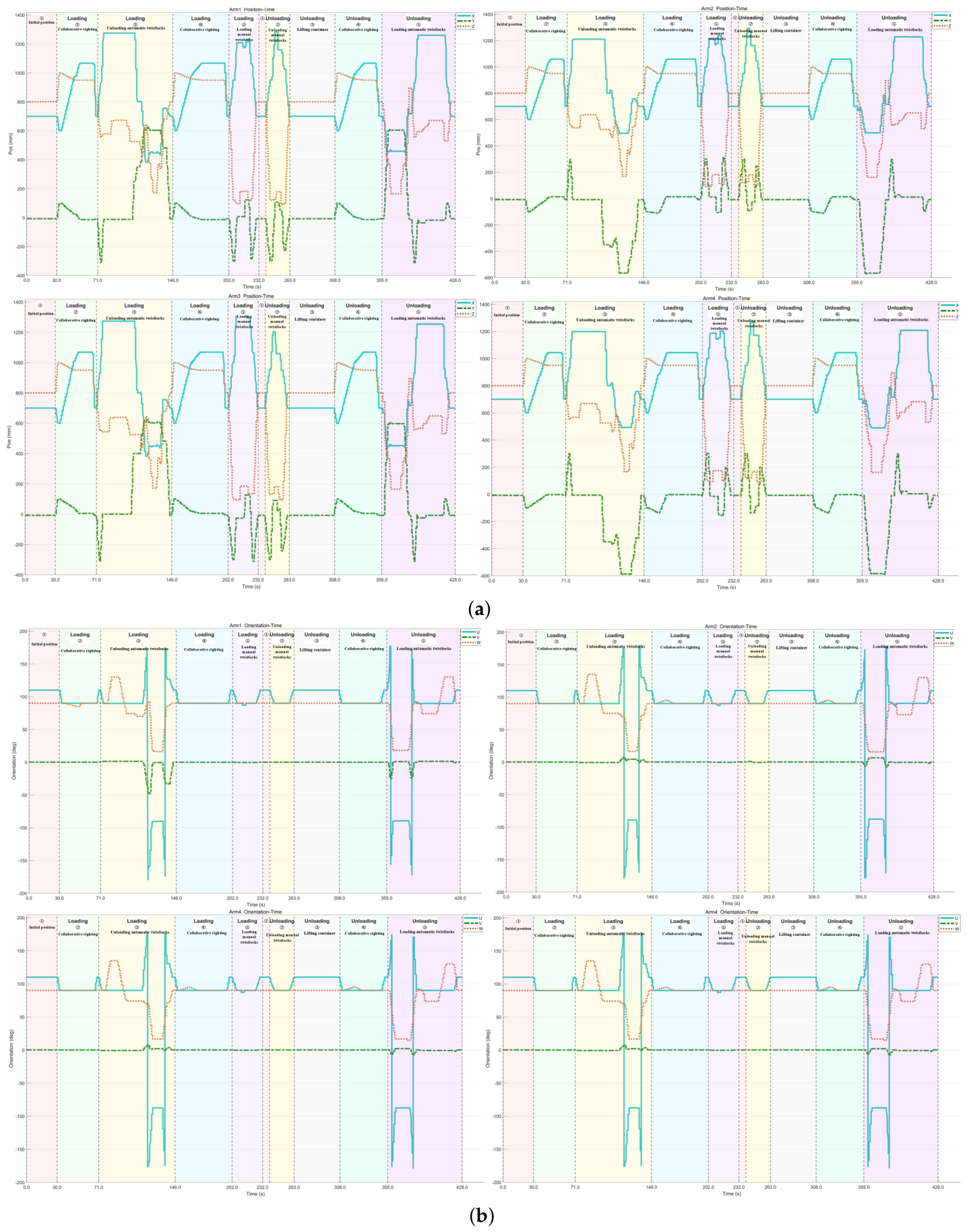
Table 4 shows the duration times of manual and automatic operations. Compared to manual operation, the automated operation increased efficiency by 21.26% and 14.03% for the loading and unloading processes, respectively. For high-frequency, repetitive tasks, this cumulative efficiency gain is significant. Figure 18 shows the motion curves for one complete automated loading/unloading process. In addition, the success rates of automated loading and unloading operations are 95% and 91%, respectively.
The ‘automated time’ reported in Table 4 excludes the human-controlled crane travel to/from the workspace, but includes the time from the moment the operator stops the crane at the target height to the moment the last manual twist lock is engaged. Operator behavior was standardized via on-screen prompts and voice commands; reaction time variance was below 2 s across trials.
Beyond efficiency, the system offers substantial comprehensive benefits. The time saved per operation translates into significant labor and time cost savings in the context of high daily throughput. More importantly, it frees workers from high-intensity, high-risk repetitive tasks to higher-value roles like equipment monitoring and management, achieving the goals of “reducing manpower, enhancing safety, and improving efficiency.” The system also provides operational consistency, high precision, and 24/7 operation, reducing equipment damage, material spillage, and accidents caused by human error, yielding profound intangible benefits in production stability, safety, and quality.

7.3. Computational Resource Evaluation for Edge Deployment

The deep learning perception module is deployed on an industrial computer (Intel Core i7-12700, 32 GB RAM, NVIDIA RTX 3060 12 GB) mounted near the crane. Table 5 reports the model size, computational complexity, and measured inference speed.
The end-to-end perception latency (camera capture → YOLO detection → 3D projection) is 28 ms, well below the 100 ms control cycle requirement. Even under worst-case dust or low light, inference time remains stable ( ± 2 ms). This confirms that the system can run in real time on edge industrial hardware without offloading to a remote server.

7.4. Ablation Study and Baseline Comparisons

To quantify the contribution of key components in the proposed system, four ablation experiments were conducted under the same protocol described in Section 7.2 (20 trials for the full system, 10 trials for each ablation). The results are summarized below.
(a) UWB+IMU only (vision disabled). In this configuration, the depth cameras and YOLOv8 perception were turned off, and only UWB and IMU provided pose estimates for alignment. The alignment success rate dropped to 40% (4 out of 10 trials) because the UWB/IMU fusion (accuracy ∼10 cm) was insufficient for precise twist lock grasping, which requires millimeter-level positioning. The remaining six trials failed due to misalignment exceeding the allowable tolerance (>10 mm).
(b) UWB+IMU+vision with a single manipulator. Only one manipulator (arm No. 1) was used for alignment, while the other three arms remained stationary. The task could not be completed in any of the 10 trials because a single arm cannot constrain the box’s rotational degree of freedom; the box would rotate or tilt during pushing, leading to a success rate of 0%. This confirms that at least two opposing manipulators are necessary for stable alignment.
(c) Consensus control replaced with independent PID. Each manipulator was controlled by an independent PID controller that tracked its own goal pose without the consensus term ( K c = 0 ). The average alignment time increased from 45.9 s (with consensus) to 112.5 s, and manual intervention was required in 6 out of 10 trials because the box would tilt or become wedged due to inconsistent motion among the arms. This demonstrates the critical role of the multi-agent consensus scheme in coordinating the four manipulators.
(d) Vision using YOLOv5 instead of YOLOv8. The YOLOv8 detector was replaced by YOLOv5 (same training dataset). The detection mean average precision (mAP@0.5) dropped from 0.92 to 0.78, and four trials (40%) failed because the corner castings or manual twist locks were missed. The remaining trials required longer manual verification time. This highlights the advantage of YOLOv8’s improved feature extraction for mining warehouse environments.
Overall, these ablation results confirm that the full system—integrating UWB/IMU for coarse positioning, multi-depth-camera vision for fine perception, four manipulators for multi-point constraint, and consensus-based collaborative control—is essential for achieving reliable and efficient automated loading/unloading.

7.5. Failure Mode Analysis and Recovery

The system is designed to handle multiple failure modes with specific detection and recovery actions. When UWB signal loss is detected (no new data for >0.5 s), the system pauses, alerts the operator, and falls back to IMU-only drift mode for a maximum of 5 s. If IMU drift exceeds 10 (detected by comparison with vision), the ESKF is reinitialized using the vision-based pose estimate. Depth camera occlusion is identified when the depth map coverage of the region of interest falls below 30 % ; the system then switches to an adjacent camera and reduces manipulator speed. When YOLO confidence remains below 0.5 for more than 10 consecutive frames (monitored via logits), the system retries detection after 1 s; if the low confidence persists, it pauses and alerts the operator. A manipulator joint fault is detected by motor torque anomaly, triggering immediate stop of all arms, brake engagement, and HMI notification for manual recovery. For all failures, the system enters a safe state (all actuators stopped, crane brake engaged), and the HMI displays a specific error code with recovery instructions. No single-point failure leads to uncontrolled motion or drop of the transport box.

7.6. Limitations and Realism Plan

The current experiments were conducted in a laboratory/warehouse environment without underground-specific stressors (high humidity, vibration, EMI, coal dust). To bridge this gap, we performed staged stress tests: (i) dust injection up to 50 mg/m3 reduced vision mAP from 0.92 to 0.83, still above the 0.7 threshold for safe operation; (ii) vibration table (10–50 Hz, 2 mm amplitude) increased UWB noise to 12 cm RMSE, still within tolerances; (iii) simulated UWB multipath (by adding reflectors) caused occasional false lock detection, mitigated by temporal consistency checks. Full underground trials are pending safety certification. Future work will report performance metrics in an operational mine.

8. Conclusions

Material transportation in mining warehouses is a critical area in the coal industry. With the ongoing upgrade towards intelligence and automation, increasing research is focused on material transportation, extending to broader applications. This paper proposes an intelligent loading system for standardized mining material transportation based on multimodal perception and multi-arm collaboration, along with its key technologies. Through analysis of design requirements, a complete loading/unloading workflow was established, and each system module was detailed, utilizing various technologies and methods for automated material transport and handling.
The system comprises five modules: a standardized carrier platform and modular transport boxes, a box locking and spreader module, a multi-sensor recognition and positioning module, a multi-manipulator collaborative loading/unloading module, and a perception feedback and (human-controlled) overhead crane module. It involves three key technologies: standardization of the carrier platform and modularization of transport boxes; multimodal perception data fusion and recognition positioning; and multi-manipulator collaborative control.
1.
Standardized Carrier Platform and Modular Transport Box Technology based on Separable and Easily Detachable Design: Based on standardization and modularity principles, an open-top modular transport box and standardized carrier platform were designed. This includes a semi-automatic spreader for box lifting, manually operable twist locks for fixing boxes to the platform, and automatic twist locks for stacking boxes.
2.
Multimodal Perception Data Fusion and Recognition Positioning Technology based on Multiple Depth Cameras + UWB + IMU: Multiple depth cameras, UWB units, and IMU sensors were configured. Intelligent perception algorithms were developed to quickly recognize the overall pose of the modular transport box, calculate its relative pose to the carrier platform, guide the multi-manipulator collaborative control, and ensure real-time, fast, and secure data transmission.
3.
Multi-Manipulator Collaborative Control Technology based on Multi-Agent Error Consensus: A vision-guided and error consensus-based multi-manipulator collaborative control method was designed, utilizing real-time pose data from the recognition module. It employs a “two-master, two-slave” architecture, where master arms adaptively plan pushing trajectories based on box deflection, and slave arms track in real time. A weighted control strategy combining individual and system consensus errors achieves high-precision collaborative alignment, twist lock operations, and pose adjustments, significantly enhancing the automation level, coordination, and robustness of the loading/unloading process.
Additionally, a human–machine collaborative information monitoring system technology was investigated. An HMI software was developed, using image acquisition interfaces to monitor the relative state of the box and platform in real time. When the box reaches the predetermined position, the operator receives a prompt to stop the crane via the software. Manipulators then collaboratively align the box. Once aligned, a signal prompts the operator to slowly lower the box while the manipulators maintain its stable pose. During operation, the system also monitors personnel in the work area for safety warnings.
Together, the standardized carrier platform and boxes, the multi-depth-camera perception pipeline, and the multi-manipulator collaborative motion module constitute an integrated material-loading system with supporting information software. It can replace manual loading, adapt to harsh environments, and achieve standardized transport and automated loading. The authors expect the system to be competitive within the domestic coal industry and to reach an internationally comparable technical level. The system is safe and reliable, with self-diagnosis and minor fault auto-recovery functions. Faults that cannot be auto-recovered are displayed on the HMI. Maintenance is convenient, aiming for minimal maintenance.
As the transport boxes and carrier platform are intended for underground use, the system is currently undergoing application for Coal Mine Safety Certification. Despite the promising results, the current system has several technical limitations: (1) Under extreme dust (>50 mg/m3) or ultra-low illumination (<50 lux), YOLOv8 detection recall for manual_lock_black drops below 0.5. (2) In enclosed metal environments, UWB multipath degrades 3D positioning to >15 cm RMSE. (3) Upon a single manipulator failure, the remaining three arms cannot perform four-point twist lock operations. Future work will address these via multi-spectral vision, UWB+LiDAR fusion, and fault-tolerant control reconfiguration and focus on system refinement, production application, and developing an information system for mining material transportation based on this system to enable traceable and digital management of material transport and storage.


Author Contributions

Conceptualization, G.C., Z.Z. and Y.W.; methodology, G.C., Z.Z. and Y.W.; software, H.D., A.C., C.L. and X.Z.; validation, H.D., A.C., C.L. and X.Z.; formal analysis, H.D., A.C., C.L. and X.Z.; investigation, G.C., Y.W. and Z.Z.; resources, G.C., Z.Z. and Y.W.; data curation, H.D., A.C., C.L. and X.Z.; writing—original draft preparation, G.C., Y.W. and H.D.; writing—review and editing, G.C. and S.G.; visualization, H.D., A.C., C.L. and X.Z.; supervision, G.C. and S.G.; project administration, G.C., Y.W. and S.G.; funding acquisition, G.C., Y.W. and S.G. All authors have read and agreed to the published version of the manuscript.

Funding

This research was funded by the Huaneng Group Headquarters Technology Project “Development of Standardized Material Transport Platform and Intelligent Loading System” (grant number HNKJ22-HF130), Beijing Natural Science Foundation–Xiaomi Innovation Joint Fund Project (grant number L243013), Central Government Guides Local Science and Technology Development Fund Project (grant number 246Z1813G), Tangshan City Applied Basic Research Science and Technology Plan Project (25130201B), and National Natural Science Foundation of China (62303048).

Institutional Review Board Statement

Not applicable.
Informed Consent Statement

Not applicable.
Data Availability Statement

Data is contained within the article..

Conflicts of Interest

Yaohui Wang is employed by the Huaneng Coal Technology Research Co., Ltd and Zhidong Zhao is employed by Zhalainuoer Coal Industry Co., Ltd. The remaining authors declare that the research was conducted in the absence of any commercial or financial relationships that could be construed as a potential conflict of interest.

References

  1. Wang, G.; Liu, F.; Pang, Y.; Ren, H.; Ma, Y. Coal mine intellectualization: The core technology of high quality development. J. China Coal Soc. 2019, 44, 349–357. [Google Scholar] [CrossRef]
  2. Hu, E.; Ge, S. Coal mining robot research progress and trend analysis. J. Intell. Mine 2021, 1, 59–74. [Google Scholar]
  3. Hartlieb-Wallthor, P.v.; Hecken, R.; Kowitz, S.F.; Suciu, M.; Ziegler, M. Sustainable Smart Mining: Safe, Economical, Environmental Friendly, Digital. In Yearbook of Sustainable Smart Mining and Energy 2021: Technical, Economic and Legal Framework; Yearbook of Sustainable Smart Mining and Energy—Technical, Economic and Legal Framework; Frenz, W., Preuße, A., Eds.; Springer: Berlin/Heidelberg, Germany, 2022; Volume 1, pp. 37–79. [Google Scholar] [CrossRef]
  4. Ge, S.; Zhang, X.; Xue, G.; Ren, H.; Wang, H.; Pang, Y.; Fan, L. Development of Intelligent Technologies and Machinery for Coal Mining in China’s Underground Coal Mines. Strateg. Study Eng. 2023, 25, 146–156. [Google Scholar] [CrossRef]
  5. Wang, G.; Pang, Y.; Ren, H.; Zhan, K.; Du, M.; Zhang, Y.; Cheng, J.; Du, Y.; Zhang, J.; Gong, S.; et al. System engineering and key technologies research and practice of smart mine. J. China Coal Soc. 2024, 49, 181–202. [Google Scholar] [CrossRef]
  6. Huang, Z.; Ge, S.; He, Y.; Wang, D.; Zhang, S. Research on the Intelligent System Architecture and Control Strategy of Mining Robot Crowds. Energies 2024, 17, 1834. [Google Scholar] [CrossRef]
  7. Ge, S.; Hu, E.; Li, Y. New progress and direction of robot technology in coal mine. J. China Coal Soc. 2023, 48, 54–73. [Google Scholar] [CrossRef]
  8. Ge, S.; Hu, E.; Pei, W. Classification system and key technology of coal mine robot. J. China Coal Soc. 2020, 45, 455–463. [Google Scholar] [CrossRef]
  9. Bao, J.; Liu, Q.; Ge, S.; Yuan, X.; Yin, Y.; Zhang, L. Research status and development trend of intelligent technologies for mine transportation equipment. J. Intell. Mine 2020, 1, 78–88. [Google Scholar]
  10. Chen, Y.; Huo, Z.; Liu, Z.; Zhang, Y. Development trend and key technology of coal mine transportation robot in China. Coal Sci. Technol. 2020, 48, 233–242. [Google Scholar]
  11. Zhao, Y.; Ji, Q.; Wang, T. Current status and prospects of intelligent trackless auxiliary transportation technology in coal mines. Coal Sci. Technol. 2021, 49, 209–216. [Google Scholar]
  12. Su, Y. Key technologies of auxiliary transportation robots in coal mines. West-China Explor. Eng. 2021, 33, 119–120. [Google Scholar]
  13. Chen, M. Design of Auxiliary Transport and Transfer Robot in Coal Mine. Mod. Manuf. Technol. Equip. 2024, 60, 58–63. [Google Scholar] [CrossRef]
  14. Xu, J. Design of Coal Mine Auxiliary Transport Transfer robot. Mech. Manag. Dev. 2024, 39, 127–129. [Google Scholar]
  15. Zhou, P. Research and application of intelligent robot for auxiliary transportation in Buliangou Coal Mine. China Coal 2021, 47, 147–151. [Google Scholar] [CrossRef]
  16. Liang, H.; Yang, Z.; Cao, L. Intelligent inspection robot system of coal mine transportation system. Coal Eng. 2024, 56, 220–224. [Google Scholar] [CrossRef]
  17. Rong, G. Research on Intelligent Inspection Robot for Coal Mine Transportation System Based on TD-LTE Technology. China Coal Ind. 2022, 2022, 62–63. [Google Scholar]
  18. Zhou, D. Research on key technologies of multi-agent control system for trackless transportation robot in coal mines. Saf. Coal Mines 2024, 55, 213–218. [Google Scholar] [CrossRef]
  19. Bao, J.; Zhang, Q.; Ge, S.; Hu, E.; Yuan, X.; Yang, Y.; Yin, Y.; Lyu, Y. Basic research and application practice of unmanned auxiliary transportation system in coal mine. J. China Coal Soc. 2023, 48, 1085–1098. Available online: https://www.mtxb.com.cn/en/article/id/da31d9b2-a9a9-4c28-8245-70021decc59d (accessed on 21 May 2026).
  20. Cui, T.; Zheng, Z.; Sun, H. The Application of Container Transshipment Mode for Mining Materials Transportation in Gaohe Energy. Coal 2017, 26, 46–47. [Google Scholar] [CrossRef]
  21. Wang, W. Research on Design and Identification and Positioning Technology of Coal Mine Auxiliary Transportation Reprint Container. Master’s Thesis, Taiyuan University of Technology, Taiyuan, China, 2022. [Google Scholar]
  22. Tian, X. Research on Mechanical System of Mine Rail Auxiliary Transportation Container Transfer Robot. Master’s Thesis, China University of Mining and Technology, Xuzhou, China, 2023. [Google Scholar]
  23. Hao, M. Design of mine wheeled material transport robot. Coal Sci. Technol. 2022, 50, 270–276. [Google Scholar] [CrossRef]
  24. Yan, J.; Wang, Q.; Cheng, Y.; Su, Z.; Zhang, F.; Zhong, M.; Liu, L.; Jin, B.; Zhang, W. Optimized single-image super-resolution reconstruction: A multimodal approach based on reversible guidance and cyclical knowledge distillation. Eng. Appl. Artif. Intell. 2024, 133, 108496. [Google Scholar] [CrossRef]
  25. Hu, X.; Jiang, C.; Huang, Y.; Peng, D.; Su, H.; He, Y.; Chen, Z. SMNet: A Novel Compositional Generalization Model for Industrial Robot Multijoint Fault Diagnosis. IEEE Internet Things J. 2026, 13, 13005–13018. [Google Scholar] [CrossRef]
  26. Wang, X.; Jiang, H.; Dong, Y.; Mu, M. Spatial-channel collaborative multi-scale graph interaction deep transfer learning for unsupervised rotating machinery fault diagnosis. Eng. Appl. Artif. Intell. 2026, 176, 114691. [Google Scholar] [CrossRef]
  27. Liang, P.P.; Zadeh, A.; Morency, L.P. Foundations & Trends in Multimodal Machine Learning: Principles, Challenges, and Open Questions. ACM Comput. Surv. 2024, 56, 1–42. [Google Scholar] [CrossRef]
  28. Jiang, Z.; Zhu, H.; Liu, R.; Hu, X.; Zhang, W. Social GAN guided multimodal trajectory prediction and MPC for autonomous driving. Robot Learn. 2025, 2, 0010. [Google Scholar] [CrossRef]
  29. Wu, Q.; Zhao, H.; Chen, X.; Zhao, Y. Review of Technology, Application Status and Development Trend in Multi-arm Cooperative Robots. J. Mech. Eng. 2023, 59, 1–16. [Google Scholar] [CrossRef]
  30. Li, F.; Li, N.; Zou, H.; Jin, Y.; Zhang, C. Attitude Control for Emergency Recovery Based on Reinforcement Learning Method for Dual-arm Space Robots. J. Nanjing Univ. Aeronaut. Astronaut. 2025, 57, 467–474. [Google Scholar] [CrossRef]
  31. Cui, Y.; Pu, J.; Hu, N.; Cui, M. Smooth and efficient motion planning of large-scale and cooperative multi-arm tunnel drilling robot. Intell. Robot. 2025, 5, 450–473. [Google Scholar] [CrossRef]
  32. Chen, G.; Yang, Q.; Li, J.; Chen, C.L.P.; Yang, C. Cooperative Control Framework for Dual-Arm Robot Enhanced by Vision Language Model and Reinforcement Learning. IEEE Trans. Autom. Sci. Eng. 2026, 23, 4314–4328. [Google Scholar] [CrossRef]
  33. Wang, Y.; Guo, S.; Zhang, J.; Ding, H.; Zhang, B.; Cao, A.; Sun, X.; Zhang, G.; Tian, S.; Chen, Y.; et al. Optimized Design and Deep Vision-Based Operation Control of a Multi-Functional Robotic Gripper for an Automatic Loading System. Actuators 2025, 14, 259. [Google Scholar] [CrossRef]
  34. Xie, C.; Zhang, P.; Fei, H. Current Status and Development Trend of Container Twist Lock Technology. China Water Transp. 2015, 15, 38–40+132. [Google Scholar]
  35. Liu, H. Research on Target Recognition and Localization Method Based on Multi-Camera. Master’s Thesis, North China Electric Power University, Beijing, China, 2021. [Google Scholar] [CrossRef]
  36. Chen, W.; Chi, W.; Ji, S.; Ye, H.; Liu, J.; Jia, Y.; Yu, J.; Cheng, J. A survey of autonomous robots and multi-robot navigation: Perception, planning and collaboration. Biomim. Intell. Robot. 2025, 5, 100203. [Google Scholar] [CrossRef]
  37. General Administration of Quality Supervision, Inspection and Quarantine of the People’s Republic of China and Standardization Administration of China. Narrow Gauge Mine Cars—Part 5: Flat Deck Car: GB/T 2885.5-2008; China Standards Press: Beijing, China, 2008. Available online: https://std.samr.gov.cn/gb/search/gbDetailed?id=71F772D80034D3A7E05397BE0A0AB82A (accessed on 21 May 2026).
  38. Liu, H. Research on Motion Control and Compliant Interaction Strategy of Cooperative Manipulator. Master’s Thesis, Shandong University, Jinan, China, 2023. [Google Scholar] [CrossRef]
Figure 1. System composition.
Robotics 15 00105 g001
Figure 2. System architecture.
Robotics 15 00105 g002
Figure 3. System operation process.
Robotics 15 00105 g003
Figure 4. Module composition and connection.
Robotics 15 00105 g004
Figure 5. Design of standardized carrier platform.
Robotics 15 00105 g005
Figure 6. Six types of modular transport boxes.
Robotics 15 00105 g006
Figure 7. Combination of open-top transport box and load-bearing platform.
Robotics 15 00105 g007
Figure 8. Multi-sensor information fusion perception method. Arrows indicate data flow with specific formats: UWB → TDoA distance vectors ( R 12 ). IMU → 3-axis acceleration + 3-axis gyro ( R 6 ). Depth cameras → RGB-D images ( H × W × 3 + H × W × 1 ). Fusion output → 6-DOF pose ( R 6 : x , y , z , roll , pitch , yaw ).
Robotics 15 00105 g008
Figure 9. Architecture of multimodal perception and localization system.
Robotics 15 00105 g009
Figure 10. Principles of tightly coupled fusion of UWB-IMU. Data shapes: UWB raw ranges ( R 12 ), IMU readings ( R 6 ), ESKF outputs pose at 1 kHz ( R 6 with covariance R 6 × 6 ).
Robotics 15 00105 g010
Figure 11. Schematic diagram of 3D information acquisition. Input: RGB image ( 640 × 480 × 3 ) and depth map ( 640 × 480 × 1 ). YOLOv8 outputs bounding boxes ( x , y , w , h , confidence, class). For each box, a 40 × 25 depth window yields a 3D point ( x , y , z ) in camera frame, then transformed to manipulator base frame ( R 3 ). The final corner pose is a 6-DOF vector ( R 6 ).
Robotics 15 00105 g011
Figure 12. Schematic diagram of depth camera YOLOv8 recognition.
Robotics 15 00105 g012
Figure 13. Schematic diagram of the manipulator collaborative box straightening, where 1–4 is the number of robotic arm.
Robotics 15 00105 g013
Figure 14. Multi-manipulator collaborative consensus control algorithm. Signals: desired pose r i ( R 6 ), actual pose y i ( R 6 ), individual error e i ( R 6 ), average error e ¯ ( R 6 ), consensus error e c , i ( R 6 ), control input u i ( R 6 ). Gains K p , K c are 6 × 6 diagonal matrices.
Robotics 15 00105 g014
Figure 15. System control architecture. Data flow annotations: IMU/UWB → 6-DOF pose ( R 6 ) at 1 kHz. Depth cameras → RGB-D images ( 640 × 480 × 3 + depth). Multi-manipulator control module → joint angle commands ( R 6 per arm). HMI displays pose and alerts. The error comparator outputs Δ e R 6 .
Robotics 15 00105 g015
Figure 16. System prototype model.
Robotics 15 00105 g016
Figure 17. System prototype experiment. (a) Lifting transport box. (b) Loading/unloading manual twist lock. (c) Loading/unloading automatic twist lock. (d) Multi-manipulator collaborative alignment.
Robotics 15 00105 g017
Figure 18. Full-process robotic arm motion curves for loading and unloading operations. (a) Position motion curve—XYZ. (b) Attitude motion curve—UVW.
Robotics 15 00105 g018
Table 1. Variables and symbols used in mathematical formulations.
SymbolDescriptionUnit/Dimension
( x i , y i , z i ) Coordinates of i-th UWB base stationm
( x tag , y tag , z tag ) UWB tag (spreader) positionm
t i Signal arrival time at i-th base stations
cSpeed of lightm/s
P c n w World coordinates of n-th corner castingm
Γ Yaw deviation of the boxrad or unitless
M , S Master and slave manipulator sets
Δ x eff Effective position deviation along X-axism
τ min , τ max Step size adaptive thresholdsm
s min , s max Minimum and maximum step sizesm/step
K p , K c Proportional and consensus gain matrices– ( 6 × 6 )
e i Individual pose error of manipulator im, rad (6-DOF)
e ¯ Average system errorm, rad (6-DOF)
u i Control input for manipulator im/s, rad/s (6-DOF)
δ x Tracking error for slave armm
( u c , v c ) Pixel coordinates of corner centerpixel
Ω Local depth search window 40 × 25 pixels
Table 2. Five types of modular transport boxes corresponding to transported materials.
No.Transport Box TypeTransported Materials
1Side-dump modular transport box (Figure 6a)Sand-like, granular, bulk materials
2Tank modular transport box (Figure 6b)Gases or liquids
3Six-post modular transport box (Figure 6c)Long strips, pipes, cables
4Double-door modular transport box (Figure 6d)Small components, manually portable items
5Open-top modular transport box (Figure 6e)Medium-sized components, parts
Table 3. Key mechanical specifications of standardized carrier platform and modular transport box.
ParameterValueTolerance
Platform length × width3000 mm × 1300 mm ± 2 mm
Twist lock spacing (length)2658 mm ± 1 mm
Twist lock spacing (width)1138 mm ± 1 mm
Lock head diameter50 mm ± 0.5 mm
Corner casting hole size60 mm × 60 mm ± 1 mm
Max payload15 tons
Allowable misalignment for locking<10 mm in X/Y, < 2 yaw
Permissible contact force per manipulator150 N (max)
Box sway amplitude (at 1.5 m rope)<150 mm (with damping)
Table 4. Comparison of manual operation and automatic operation.
ProcessSub-StepManual OperationAutomation
Loading ProcessCollaborative righting50.4 ± 5.0 s40.1 ± 3.6 s
Unloading automatic twistlocks92.6 ± 8.8 s74.3 ± 5.4 s
Collaborative righting64.9 ± 5.7 s54.1 ± 4.7 s
Loading manual twistlocks44.1 ± 4.3 s29.9 ± 2.2 s
Total252.0 ± 15.3 s198.4 ± 10.8 s
Unloading ProcessUnloading manual twistlocks37.2 ± 3.9 s27.9 ± 3.3 s
Lifting container44.3 ± 4.6 s45.8 ± 4.0 s
Collaborative righting56.5 ± 5.3 s47.2 ± 4.4 s
Loading automatic twistlocks87.9 ± 7.4 s73.3 ± 6.1 s
Total225.9 ± 13.7 s194.2 ± 11.1 s
Table 5. Computational resource consumption of YOLOv8m on deployment hardware.
MetricValue
Model file size (FP32)52 MB
Parameters25.9 million
FLOPs per image ( 640 × 640 )78.2 GFLOPs
Inference time (RGB only)9 ms
Inference time (RGB + depth post-processing)12 ms
GPU memory usage (batch = 1)2.1 GB
CPU usage (inference thread)15%
Disclaimer/Publisher’s Note: The statements, opinions and data contained in all publications are solely those of the individual author(s) and contributor(s) and not of MDPI and/or the editor(s). MDPI and/or the editor(s) disclaim responsibility for any injury to people or property resulting from any ideas, methods, instructions or products referred to in the content.