1. Introduction
In anthropomorphic robot-hand design, thumb degree-of-freedom (DOF) selection reflects a trade-off between functional opposition and system complexity. In the human hand, the thumb is the main digit responsible for opposition against the fingers, and its placement and mobility support both fine manipulation tasks, such as pinch and precision grasping, and stronger enclosure tasks, such as power grasping. Adding more degrees of freedom (DOFs) can improve thumb mobility, enhance opposition capability, and support a wider range of grasping and manipulation tasks, but it also increases the difficulty of mechanical design, actuation, and control. Reducing the number of DOFs can simplify the hardware and lower system complexity, but it may also remove mobility that is important for grasp stability and task performance. This design problem is connected to the broader biomechanical challenge of representing human joint motion through simplified kinematic models, where biological movement is described using joint coordinates, reference frames, and constraints [
1]. Similar joint-replication challenges also appear in robotic mechanisms such as the eight-bar elbow exoskeleton by Figliolini et al. [
2], supporting the need for consistent kinematic abstraction when comparing robot-thumb architectures. The main question, therefore, is not simply whether more DOFs are better, but which thumb DOFs are most worth retaining when the design must be simplified.
Existing hand-evaluation literature shows that thumb design is a key determinant of anthropomorphic hand performance. Classical benchmarks such as the Kapandji Opposition Test (KOT) [
3] provide an intuitive reachability measure of opposability, while broader frameworks such as the Anthropomorphic Hand Assessment Protocol (AHAP) [
4] and the Form-Features-Performance (FFP) index [
5] extend evaluation toward quantitative benchmarking of grasping ability, anthropomorphism, and functional performance. Recent hardware studies, including Anthro-Thumb [
6] and BiDexHand [
7], further show that richer or more biomimetic thumb-base kinematics can support improved measurable hand capability. Thumb-focused studies also show that DOF allocation and axis arrangement influence reachable task space, dexterity, and motion-force transmissibility, as demonstrated by Wang et al. [
8] and extended through alignment-sensitive opposition measures [
9] and alternative thumb-base orientation or actuation strategies [
10].
Despite these advances, the literature still lacks a controlled basis for comparing thumb DOF relevance across multiple performance metrics. Many studies introduce changes in thumb DOFs together with changes in palm shape, finger arrangement, or overall hand geometry [
5,
6,
8], which makes it difficult to isolate the effect of thumb kinematics itself. Other evaluations focus on only one metric or metric family [
8,
11], even though thumb design decisions usually require simultaneous consideration of reachability, alignment, workspace, dexterity, and grasp-related behavior [
4,
12]. Experimental validation is also relatively limited, since many studies remain largely theoretical [
8,
13], although hardware effects such as friction, compliance, tendon transmission losses, and manufacturing tolerances can significantly influence actual performance, particularly in reduced-DOF designs [
14,
15]. Accordingly, the present study addresses this gap by comparing representative thumb DOF configurations within one common hand architecture, one fixed set of hand-level boundary conditions, and one unified evaluation pipeline.
The original contribution of this work is a controlled, literature-grounded, multi-metric comparison framework for evaluating recurring anthropomorphic robot thumb DOF configurations under common hand assembly and boundary conditions. In this context, a “controlled comparison” means that the palm geometry, non-thumb fingers, reference frames, evaluation pipeline, and task definitions are kept fixed, while the thumb subsystem is varied; it does not mean that all thumb variants have identical geometry. The evaluated thumb configuration set follows the recurring design patterns identified in The Library of Approaches [
16], namely 3-1-1, 2-2-1, 2-1-1, 2-0-1, and 1-1-1. Unlike comparative studies in which thumb DOF changes are coupled with changes in palm geometry, finger arrangement, reference frames, or evaluation metrics, the proposed framework compares these configurations under one common hand architecture, combines multiple thumb-performance metrics within one unified evaluation pipeline, and complements the theoretical analysis with targeted experimental validation of selected reduced-DOF cases. In this way, thumb DOF selection is treated not as an intuitive design choice, but as a controlled and evidence-based comparison problem.
The objective of this paper is to compare representative thumb DOF configurations from the anthropomorphic robot hand literature within this controlled evaluation framework. This leads to three explicit research questions:
How do thumb DOF allocations that are qualitatively similar differ quantitatively in workspace, dexterity, opposition alignment, and grasp opportunity?
Which thumb motions are most important to retain when thumb kinematic complexity is reduced?
Do the theoretical trends remain valid when selected configurations are implemented physically?
These questions are addressed by evaluating all selected configurations on the same base hand model while keeping the palm, non-thumb fingers, and reference frames fixed. Configuration-specific thumb adaptations required for feasible opposition or fixed-joint representation are reported explicitly and considered in the interpretation. Performance is evaluated using a Denavit–Hartenberg-based theoretical framework and targeted experimental validation on a manual tendon-driven test bench.
The rest of the paper is structured as follows:
Section 2 presents the materials and methods,
Section 3 reports the results,
Section 4 discusses the findings and limitations, and
Section 5 concludes the paper.
2. Materials and Methods
This section describes the controlled comparison framework, including the common hand model, thumb-configuration definition, DH-based kinematics, theoretical metric calculation, and targeted experimental validation.
2.1. Methodology Overview
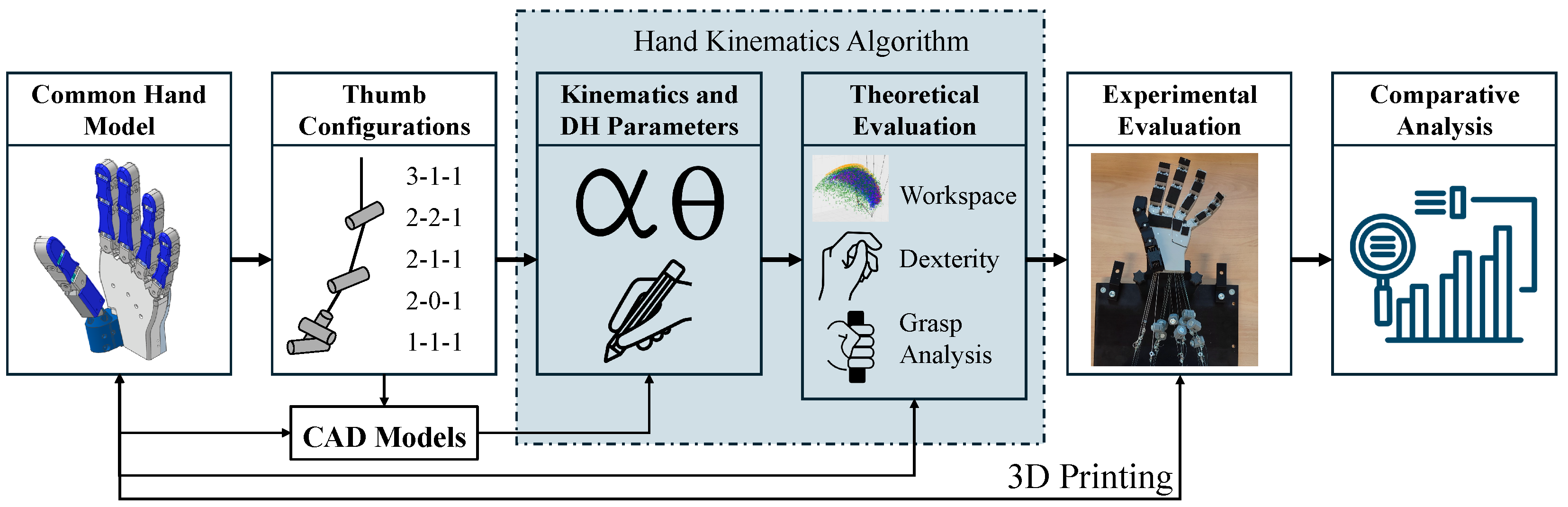
The methodology compares recurring thumb DOF allocations by varying only the thumb subsystem within a common hand-level framework. As summarized in
Figure 1, the palm and non-thumb fingers were kept fixed, while five thumb configurations were implemented in the same hand assembly and evaluated using a shared Denavit–Hartenberg (DH)-based kinematic model. The resulting sampled workspaces were used to compute opposition, workspace volume, workspace compactness, dexterity, and grasp-related metrics under identical algorithmic assumptions. Selected reduced-DOF cases were then tested on a manual tendon-driven test bench to examine whether the main theoretical trends remained meaningful in hardware.
2.2. Model Assets and Controlled Comparison Design
This study used a controlled hand-model design to isolate the effect of thumb DOF allocation. The palm and non-thumb finger CAD geometry, shown in
Figure A1, were adopted from the anthropomorphic hand model reported by Gossen et al. [
17], while only the thumb model was varied within the same modular hand assembly. The CAD model preparation and configuration-specific thumb modifications were performed in Autodesk Inventor Professional 2025, build 407 (Autodesk, Inc., San Francisco, CA, USA). This arrangement ensured that differences in performance metrics were attributable primarily to thumb kinematics rather than to changes in overall hand morphology.
Each final thumb model was required to satisfy minimum qualitative opposition before quantitative evaluation. During CAD development, all configurations were checked against the Kapandji Opposition Test (KOT) [
3]. If a configuration failed this screening step, configuration-specific adjustments to joint inclination, twist angle, or phalanx length were introduced only until qualitative feasibility was recovered. As defined in the Introduction, the controlled comparison fixes the surrounding hand architecture and evaluation conditions while allowing configuration-specific thumb implementation. Some reduced-DOF variants, therefore, required geometric adaptation or fixed-posture definition to remain physically meaningful within the shared hand model. These adaptations were treated as feasibility-restoration constraints rather than independent performance optimizations. Accordingly, the results in
Section 3 should be interpreted as comparisons of feasible representative thumb configurations under shared boundary conditions, while recognizing that thumb geometry and DOF allocation are not fully separable in all reduced-complexity designs.
2.3. Thumb Configuration Definition
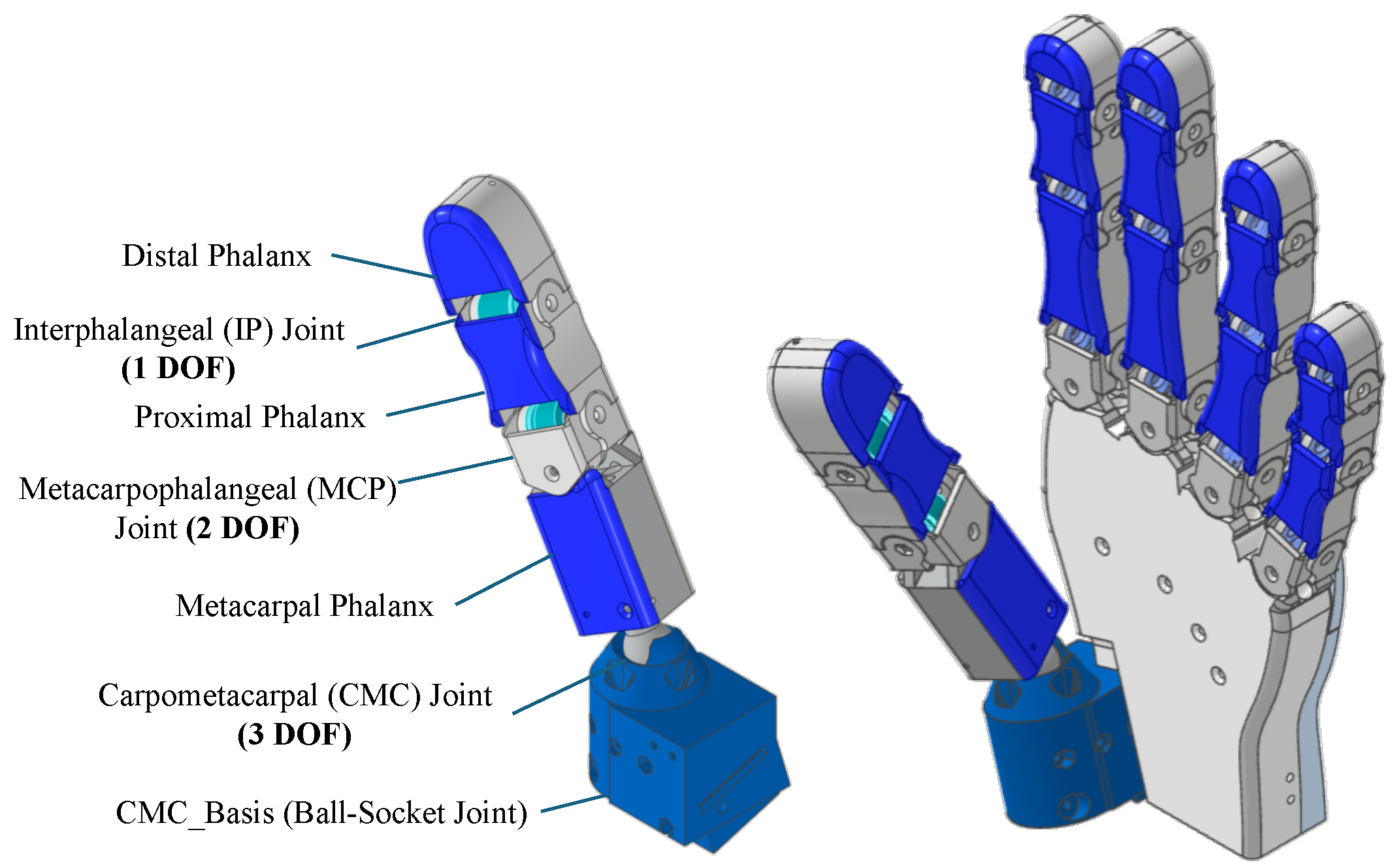
The thumb architectures compared in this study are defined using the notation a-b-c, where a, b, and c denote the rotational DOFs at the Carpometacarpal (CMC), Metacarpophalangeal (MCP), and Interphalangeal (IP) joints, respectively. This notation provides a compact description of how thumb mobility is distributed across the three anatomical joint locations.
The evaluated configurations were selected from the literature-based classification reported by Gossen et al. [
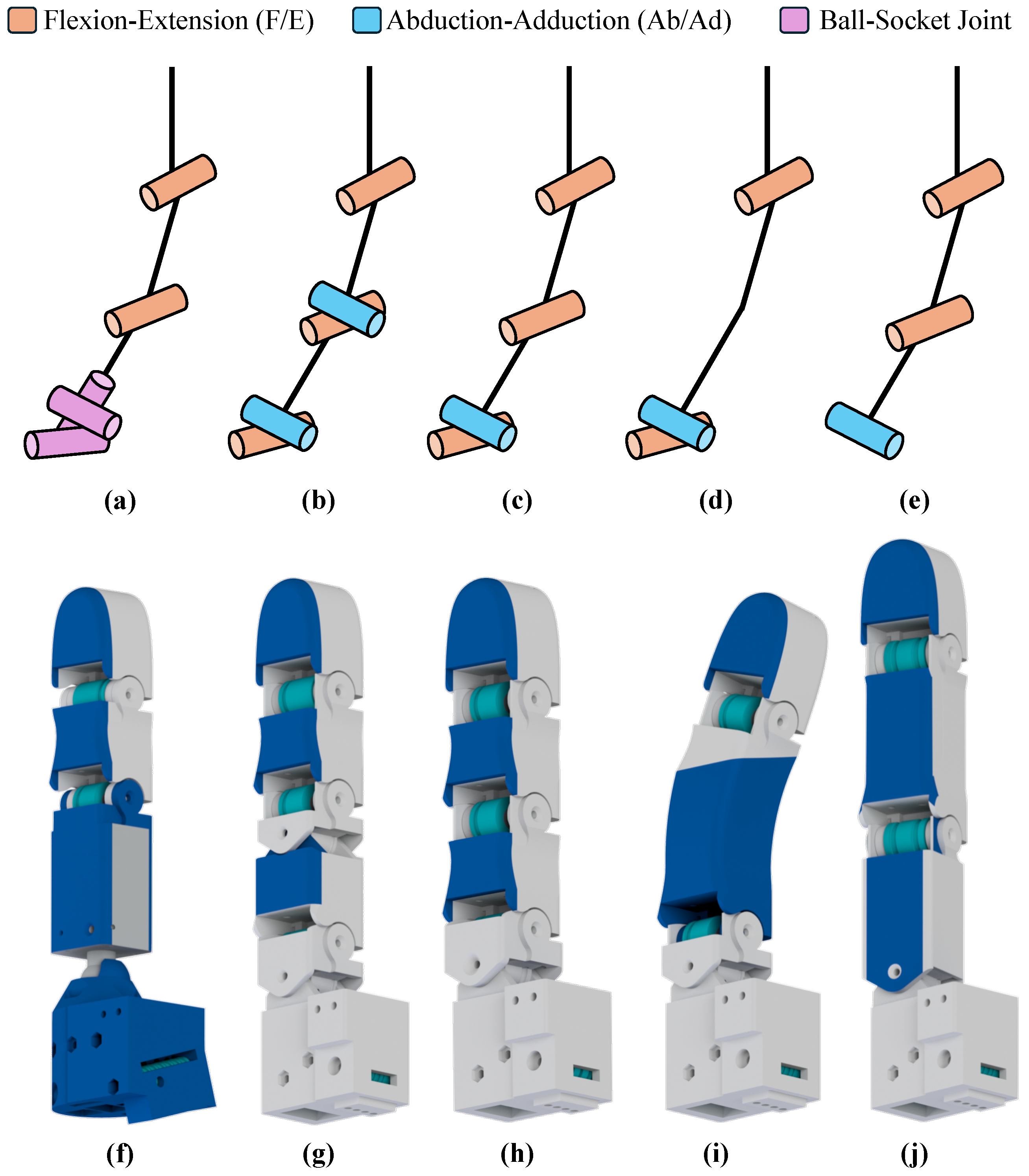
16]. The recurring thumb types 3-1-1, 2-2-1, 2-1-1, 2-0-1, and 1-1-1 were identified from anthropomorphic robot hands reported since 2000. These configurations span the main 3-, 4-, and 5-DOF thumb design cases used in robotic hand development. Representative applications are summarized in
Table 1, and the corresponding thumb schematics and CAD assemblies used in the present study are shown in
Figure 2.
The five selected configurations represent distinct levels and forms of thumb simplification. The 3-1-1 case serves as the high-mobility reference, while 2-2-1 and 2-1-1 represent intermediate reductions that differ in whether MCP abduction–adduction (Ab/Ad) is retained. The 1-1-1 case represents the minimal serial architecture, whereas 2-0-1 replaces active MCP mobility with a fixed functional posture. Together, these cases allow comparison of both progressive DOF reduction and the difference between retaining, removing, or replacing a joint DOF with a fixed offset.
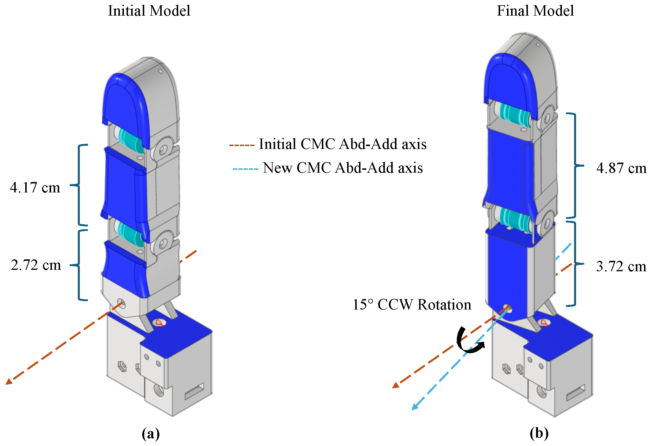
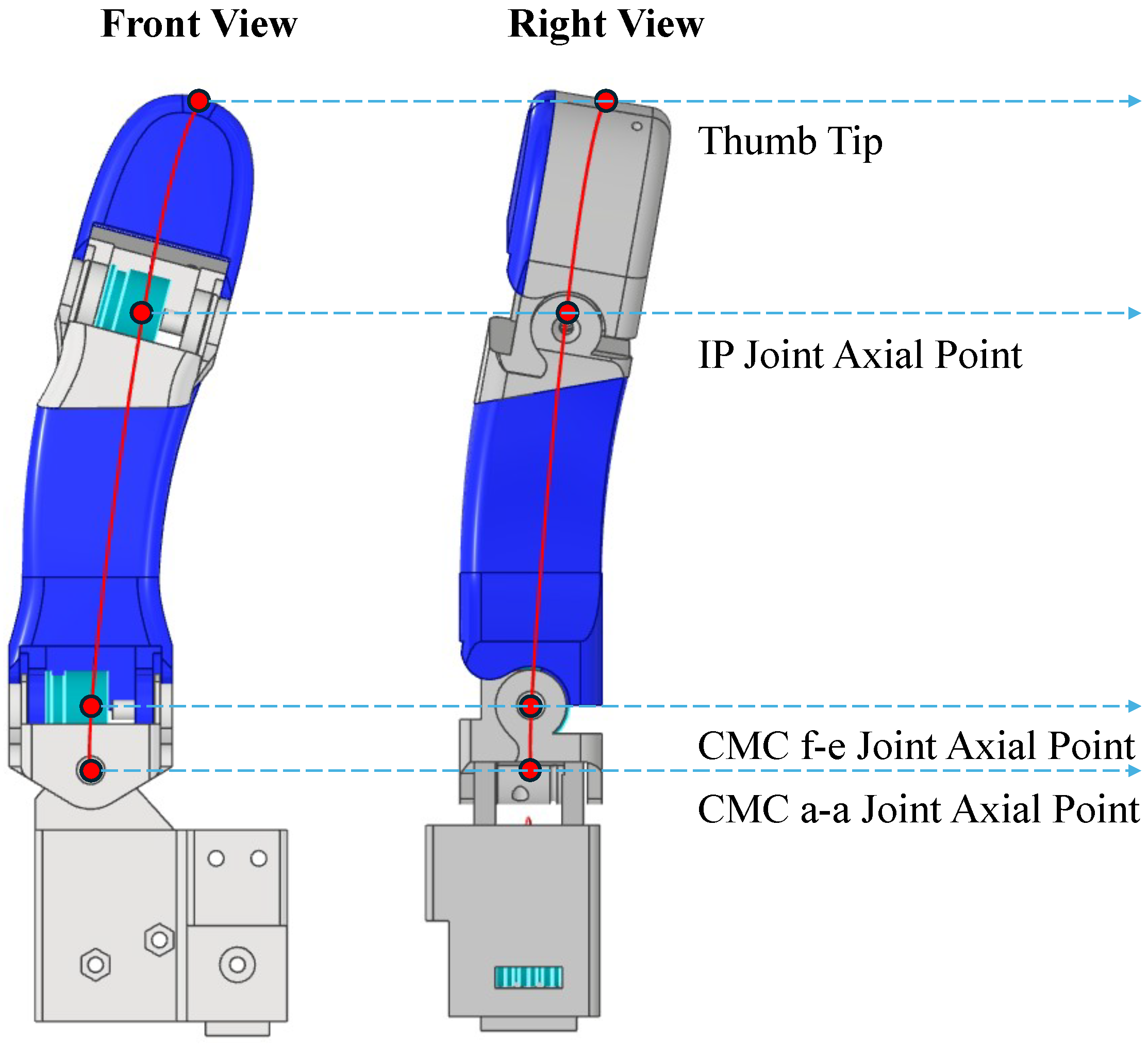
The final CAD variants include configuration-specific adaptations required to preserve feasible opposition under the common hand geometry. All variants passed the initial qualitative screening except 1-1-1. For this case, the base CMC twist and the proximal phalanx and metacarpal lengths were iteratively adjusted until the minimum Kapandji contact requirement was recovered. The resulting variant used a
counterclockwise base CMC twist and a combined 1.68 cm increase in proximal phalanx and metacarpal length, raising total thumb length from 9.98 cm to 11.66 cm, as shown in
Figure A2. This adjustment was introduced only to recover the minimum opposition feasibility of the reduced-DOF representative within the shared palm-finger geometry; it was not used to optimize workspace volume, dexterity, or grasp performance.
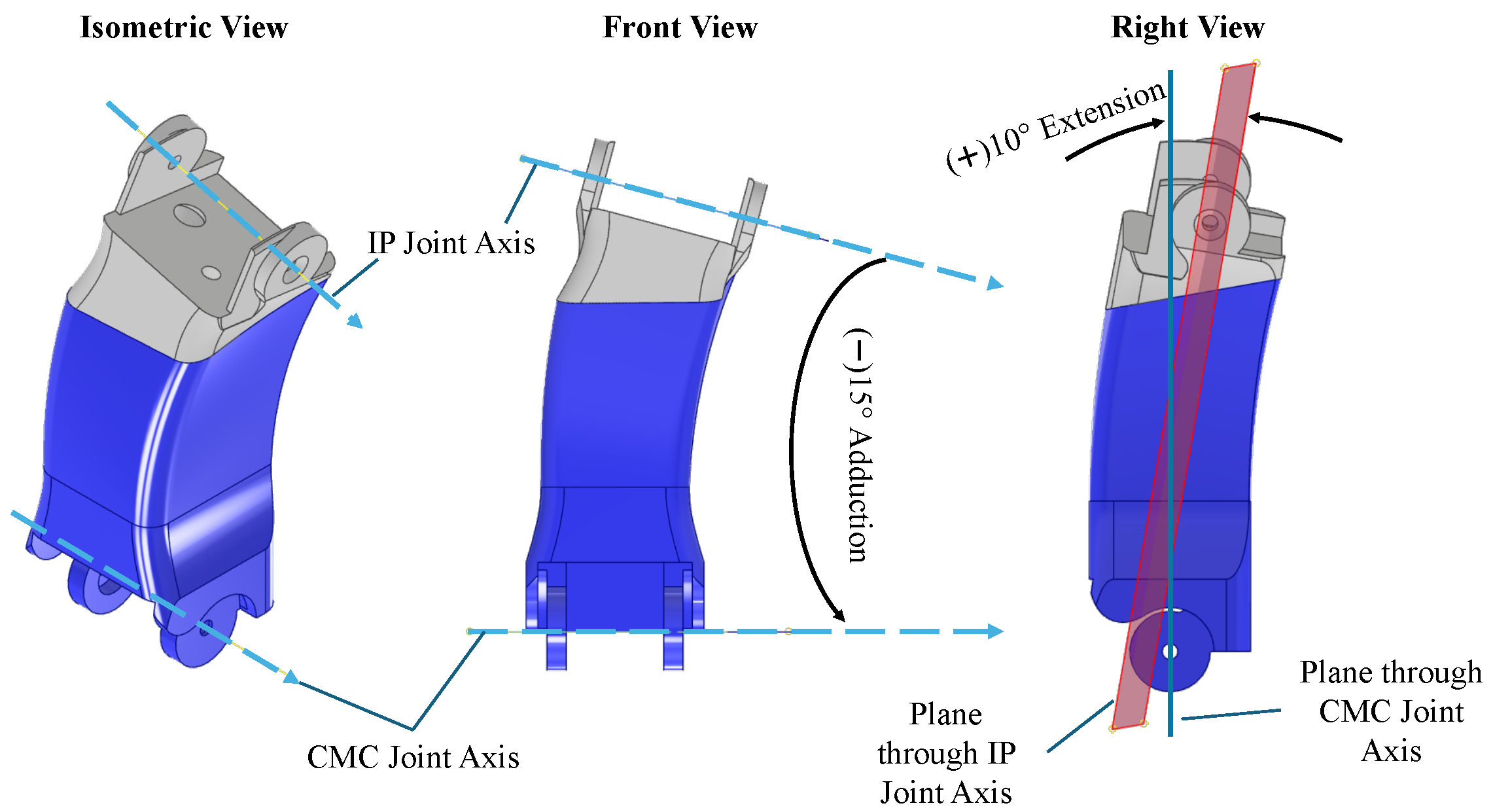
For the 2-0-1 model, the fixed MCP posture was adopted from Pulleyking et al. [
29], using
adduction and
extension, as shown in
Figure A3. The 2-0-1 case should therefore be interpreted as a fixed-posture MCP representative, in which the selected fused posture may affect the resulting workspace, alignment, and grasp metrics in addition to the loss of active MCP motion.
2.4. Kinematics Algorithm and DH Parameters
This subsection translates the finalized hand models into a common Denavit–Hartenberg (DH)-based kinematic representation so that all thumb configurations can be evaluated under identical forward kinematics assumptions. In the algorithm, the anthropomorphic robot hand was modeled as five independent serial kinematic chains attached to a common wrist reference frame. Each chain represented one digit, and its end-effector pose was obtained through forward kinematics using a consistent assignment of local coordinate frames and DH parameters. Because the palm and non-thumb fingers remained unchanged across the compared cases, the same finger-chain definitions were retained throughout, while only the thumb-related DH parameters varied between configurations. All kinematic modeling, workspace sampling, metric computation, and data processing were implemented in Python 3.11 (Python Software Foundation, Wilmington, DE, USA). Numerical operations were performed using NumPy 1.26.4, convex-hull computation using SciPy 1.15.3, and data visualization using Matplotlib 3.10.3.
The DH-based representation was defined through local coordinate frames and homogeneous transformations assigned along each digit chain. A local coordinate frame was attached to every thumb and finger joint, and additional reference frames were introduced where required to represent the proximal interphalangeal and distal interphalangeal inclinations of the ring and little fingers in a geometrically consistent manner. The relative pose of coordinate frame
i with respect to frame
is described by the homogeneous transformation matrix
as:
where
,
,
, and
denote the DH parameters of the
i-th link-joint pair.
The forward kinematics model then expressed the end-effector pose of each digit with respect to the wrist frame. For a generalized joint vector
, the end-effector pose with respect to the wrist frame is written as
where
is the Cartesian end-effector position and
is its orientation with respect to the wrist frame. The DH parameters for each thumb configuration and finger are reported in
Table A1, while the relevant range of motion (ROM) for each phalanx is summarized in
Table A2.
A common sampling basis was defined for all theoretical metrics so that every thumb configuration was evaluated under identical geometric and kinematic assumptions. The reachable workspace of each digit is defined as the set of end-effector positions attainable within its prescribed joint limits, as
where
and
denote the lower and upper bounds of the
i-th joint coordinate. This definition was applied consistently to the thumb and all opposing digits so that all subsequent processing used the same geometric and kinematic assumptions.
The workspace sampling procedure generated the common computational input for all subsequent theoretical metrics. For each digit chain, actuated joint coordinates were sampled within their range-of-motion limits, while non-variable coordinates were kept fixed according to the configuration-specific kinematic definition. The sample count of was selected as a practical compromise between workspace resolution and computational cost. This value was large enough to generate stable point-cloud representations for comparative evaluation across configurations while keeping repeated metric computation tractable. A global feasibility filter excluded end-effector positions with a vertical coordinate below cm to remove dorsal-side poses and retain the palm-facing region used in subsequent sections. The resulting point clouds and associated joint configurations formed the common input for all later metric-specific processing. Together, the DH parameters and workspace sampling procedure provided the common computational basis for the theoretical metrics described in the following subsection.
2.5. Theoretical Evaluation
This subsection defines the theoretical metrics used to compare the thumb configurations from the common sampled workspaces generated in
Section 2.4. The evaluation included opposition, workspace volume, workspace compactness, grasp opportunity, and dexterity, with all metrics computed using the same geometric, kinematic, and sampling assumptions.
2.5.1. Opposition Evaluation
Opposition was evaluated through a two-part formulation that separates qualitative reachability from quantitative alignment quality. The classical Kapandji Opposition Test (KOT) [
3] was retained as the qualitative opposability check and as the experimental reference for later physical validation, with its scalar output reported as the number of anatomical targets reached under the prescribed joint limits. In parallel, the opposition alignment mismatch, inspired by Lenggenhager et al. [
9], quantified alignment quality at feasible thumb-finger contact candidates by comparing local end-effector orientations.
Feasible opposition candidates were identified by matching the sampled thumb and opposing-finger workspaces through an
-neighborhood criterion. The threshold
cm was chosen as a small physical proximity tolerance for identifying plausible thumb-finger contact candidates under discretized workspace sampling. It was kept tight enough to avoid merging clearly separated non-contact poses, while still allowing near-contact configurations to be retained despite sampling discretization. Using the DH-based model and workspace sampling procedure of
Section 2.4, both workspaces were represented as sampled end-effector point clouds with associated joint configurations, and exact intersection was replaced by nearest-neighbor proximity matching. Let
and
denote the sampled thumb and opposing-finger workspaces. For each thumb point
, the nearest opposing point
is found and the Euclidean distance is computed as
A thumb-finger pair is accepted if
, so the resulting proximity-matched set is defined as
A greedy one-to-one nearest-neighbor rule was used by removing each accepted opposing-finger point from the remaining search pool. Although this introduces processing-order dependence, it still is a computationally efficient solution and the same matching rule was applied to all configurations, so the resulting statistics were used only as comparative indicators.
Opposition-pose compatibility was then evaluated by reconstructing local end-effector orientations at the matched candidates and quantifying their relative mismatch. For each pair
in
, forward kinematics was recomputed to obtain the thumb and opposing-finger frames
and
. Let
and
denote their rotational components. The orientation mismatch score
S is defined as
Lower S indicates better orientation alignment, with denoting identical orientations and . For rotation matrices, this Frobenius distance increases monotonically with the relative rotation angle between the two frames, so it provides a scalar measure of orientation-frame dissimilarity. Because this metric depends on the magnitude of relative rotation and not its axis, it was used as a comparative alignment proxy rather than as a complete physical measure of opposition quality.
In practical terms, this metric indicates whether a positionally feasible thumb-finger pair also has human-like compatible local tip orientations. Lower mismatch values indicate more similar thumb-tip and fingertip frames, which is favorable for tip-to-tip or tip-to-object opposition, whereas higher values indicate more oblique or less aligned contact. The metric therefore complements the binary KOT score, but remains a kinematic orientation proxy rather than a direct measure of contact force, friction, deformation, or grasp stability. The Frobenius norm was retained as a simple bounded orientation-mismatch proxy, while more axis-sensitive metrics such as quaternion-based or geodesic measures, as used by Llop-Harillo et al. [
33], remain possible alternatives for future work.
To express the mismatch results on an intuitive normalized scale, the median
m of the mismatch dataset was converted into an opposition accuracy percentage as
A higher opposition accuracy percentage, therefore, corresponds to a lower median orientation mismatch across the retained contact postures. The percentage should be interpreted as a normalized comparative indicator of orientation compatibility, not as a probability of successful physical grasping.
2.5.2. Workspace Volume and Compactness Evaluation
Workspace-based metrics were used to quantify both absolute thumb-tip reach and reach efficiency relative to thumb size. Following Wang et al. [
8], the feasible thumb-tip workspace from
Section 2.4 was approximated by its convex hull, whose scalar volume quantified the reachable interaction region under identical geometry and range-of-motion conditions. Larger convex-hull volumes were interpreted as better because they indicate broader reach potential for opposition and grasp-related tasks. The convex hull was used as a consistent scalar approximation of the sampled thumb-tip workspace. Because a convex hull encloses all sampled points within the smallest convex polytope, this approximation can include unreachable regions when the true workspace is non-convex. Therefore, the resulting volume was interpreted as a comparative upper-bound proxy rather than an exact workspace reconstruction. More shape-sensitive alternatives, such as alpha-shape reconstruction [
33], can represent non-convex workspace boundaries more closely, but were not used in the present work in order to preserve a simple comparison pipeline across all thumb configurations.
Workspace compactness was additionally evaluated to distinguish broad reach from geometrically inefficient design. Following Wang et al. [
8], the workspace compactness index is defined as
where
is the convex-hull workspace volume, and
is a characteristic length computed consistently from the kinematic model. The characteristic length
was taken as the anatomical thumb length
L, except for 2-0-1, where the fixed metacarpal-proximal phalanx offset was measured using the spline-based procedure shown in
Figure A4. The thumb lengths are reported in
Section 3, and higher compactness values were interpreted as better.
2.5.3. Grasp Opportunity and Best Grasp Pose Evaluation
Grasp-related evaluation quantified how effectively each thumb configuration could realize a cylindrical power grasp under a common object definition and contact model. In hand function, pinch grasp is associated with precision-oriented stabilization between the thumb and one or more fingertips, whereas power grasp encloses the object against the palm through coordinated thumb-finger action and is associated with stable, forceful holding. A cylindrical object was selected as the common grasp reference because it provides a simple and repeatable benchmark for evaluating power-grasp behavior under controlled geometric conditions.
Following the task-oriented relevance logic used by Gossen et al. [
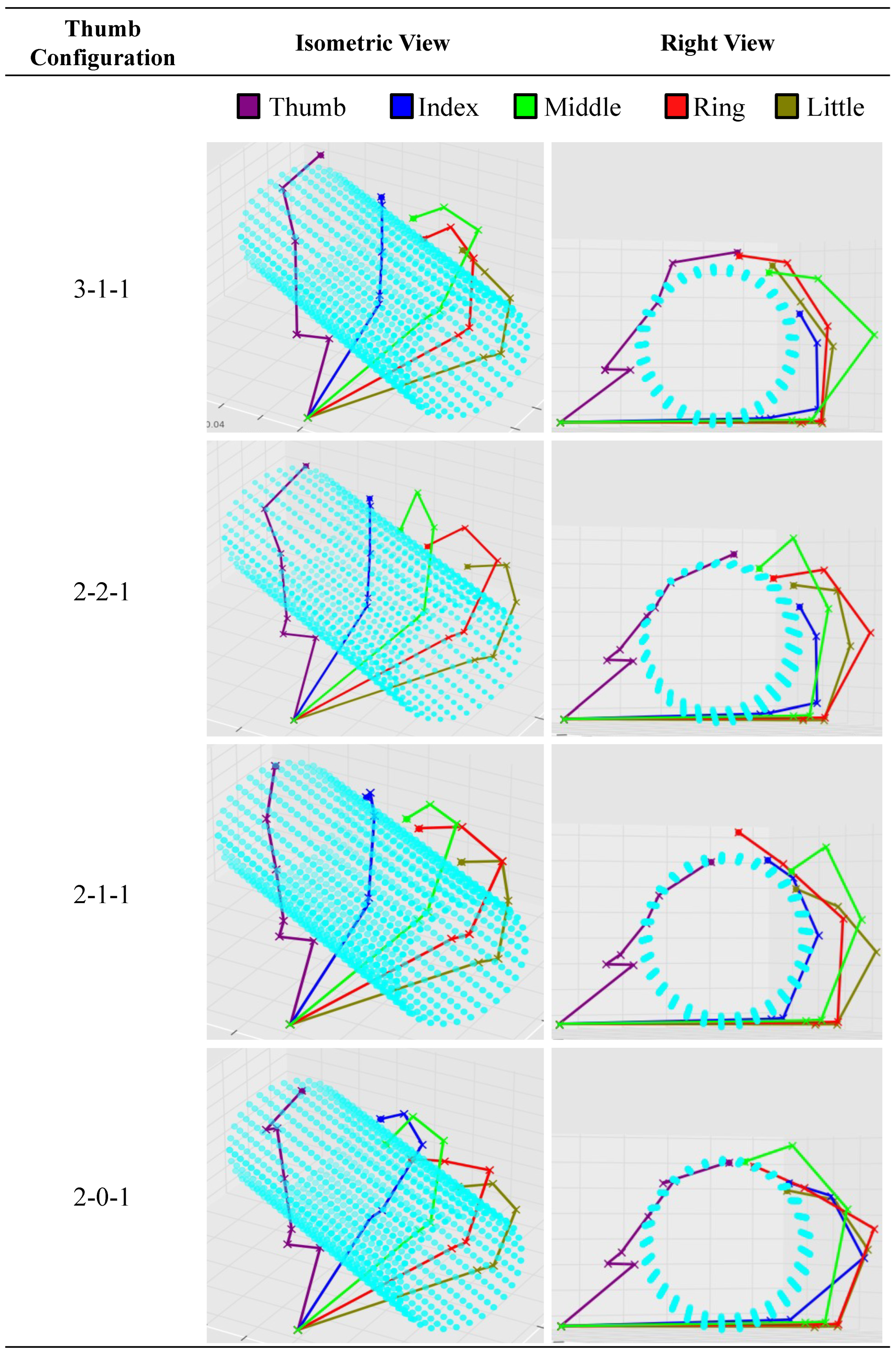
17], a 6 cm diameter cylinder was used as the theoretical reference object. Its symmetry axis was initialized along the palm
-axis and rotated by
about the palm
-axis, so all configurations were evaluated under the same object pose. The experimental evaluation later used 5, 6, and 7 cm cylinders to test grasp trends around this reference case.
Grasp candidates were generated by filtering reachable workspaces for admissible object contacts under one common contact model. Let
denote the point-cloud representation of the reference cylinder, and
denote the sampled workspace of finger
f. The candidate contact set for that finger is defined as
where
is the contact-tolerance threshold, fixed at 1 cm in the present implementation. This threshold was chosen as a broader predetermined band around the cylinder surface for candidate grasp generation rather than as a final contact criterion.
was mainly used only to retain workspace points sufficiently close to the cylinder surface before additional axial, enclosure, collision, and force-feasibility filters were applied. Finger-specific axial bounds
, an upper-half enclosure condition, and conservative collision rejection further excluded impractical, self-intersecting, or object-penetrating postures. For each retained contact, a local object-contact frame was defined and the corresponding grasp-matrix formulation was constructed under a hard-finger contact assumption. The detailed local-frame definition and grasp-matrix derivation are provided in
Appendix A.1. Each grasp candidate was then formed by combining one admissible contact point from each participating digit, including the thumb, into an
-contact tuple for grasp-force evaluation.
Grasp feasibility and the best grasp pose were determined by solving a contact-force optimization problem for each retained candidate. For a given contact set, feasibility is determined by minimizing the total contact-force norm subject to Coulomb friction constraints and static equilibrium as
subject to
and
where
contains the normal, sliding, and tangential force components at contact
i,
is the corresponding friction coefficient,
is the grasp matrix,
is the stacked contact-force vector, and
is the external wrench acting on the object. This problem was solved as a Second-Order Cone Program (SOCP). A grasp candidate was considered feasible only if the force solution satisfied both non-slip friction conditions and static equilibrium. Grasp opportunity was represented by the number of feasible candidate grasps, while the best grasp pose was defined as the feasible candidate with the smallest optimal objective value.
2.5.4. Kinematic Dexterity Evaluation
Jacobian-based dexterity was evaluated to quantify how uniformly each thumb configuration could generate translational motion and transmit forces across its reachable workspace. Based on Yoshikawa et al. [
34] and Wang et al. [
8], the translational Jacobian
was computed for each valid sampled joint vector. Its minimum and maximum singular values,
and
, were used to calculate the kinematic isotropy index
as
The Jacobian Matrix Condition Number (JMCN) was then defined as the inverse of the isotropy index
These indices were computed from the valid sampled joint vectors from
Section 2.4. Lower JMCN and higher
indicated better isotropy, more uniform motion-force transmission, and lower sensitivity to singular configurations. Dynamic dexterity was excluded because it depends on actuator and inertia assumptions outside the scope of the present structural kinematic analysis.
A local parameter sensitivity check was additionally performed to assess whether the main theoretical trends depended strongly on the selected sampling and threshold values. The check followed a strategy such that one algorithmic parameter was varied while all remaining modeling assumptions, range-of-motion limits, geometric definitions, object-pose definitions, and filtering criteria were kept unchanged. The workspace sampling count
N, which controls the sampling density of the joint ranges described in
Section 2.4, the opposition proximity threshold
, and the cylinder-contact threshold
were varied around their baseline values. The results of this sensitivity check are reported in
Section 3.5.
2.6. Equal-Weight Scorecard for Theoretical Methods
An equal-weight comparative scorecard was defined to synthesize the theoretical evaluation results across the investigated thumb configurations. The scorecard summarized the relative cross-metric balance of each configuration under one transparent baseline weighting scheme and was treated as a comparative synthesis tool rather than as a universal design index.
The scorecard was constructed by assigning configuration-wise scores for each theoretical metric and summing these scores across metrics. For Kapandji reachability, configurations achieving 11/11 targets were assigned 5 points, while configurations below this complete score were assigned 3 points. This narrower scoring range reflected the different nature of Kapandji reachability as a qualitative screening metric, since it does not generate a continuous comparative ordering when several configurations achieve the same full score. Opposition accuracy, workspace volume, workspace compactness, and candidate-grasp count were scored in descending order, with 5 points assigned to the strongest configuration and lower scores assigned to weaker configurations. Configurations with no feasible candidate grasps were assigned 0 points for candidate-grasp count, and tied values received the same score. For dexterity, the mean Jacobian Matrix Condition Number (JMCN) was scored in ascending order because lower values indicate better conditioning, whereas the mean isotropy index () was scored in descending order because higher values indicate better isotropy.
The final theoretical score was obtained by summing all metric-specific score contributions. Because this synthesis used equal weighting across distinct metric families and discretized continuous outcomes into discrete score bands, the aggregate ranking was interpreted only as a baseline theoretical summary under the adopted comparison logic, not as evidence that all metric families are equally important in all robotic-hand applications.
2.7. Experimental Evaluation
This subsection describes the hardware-based validation procedures used to examine whether selected theoretical trends remained meaningful under controlled bench conditions.
2.7.1. Manual Test Bench
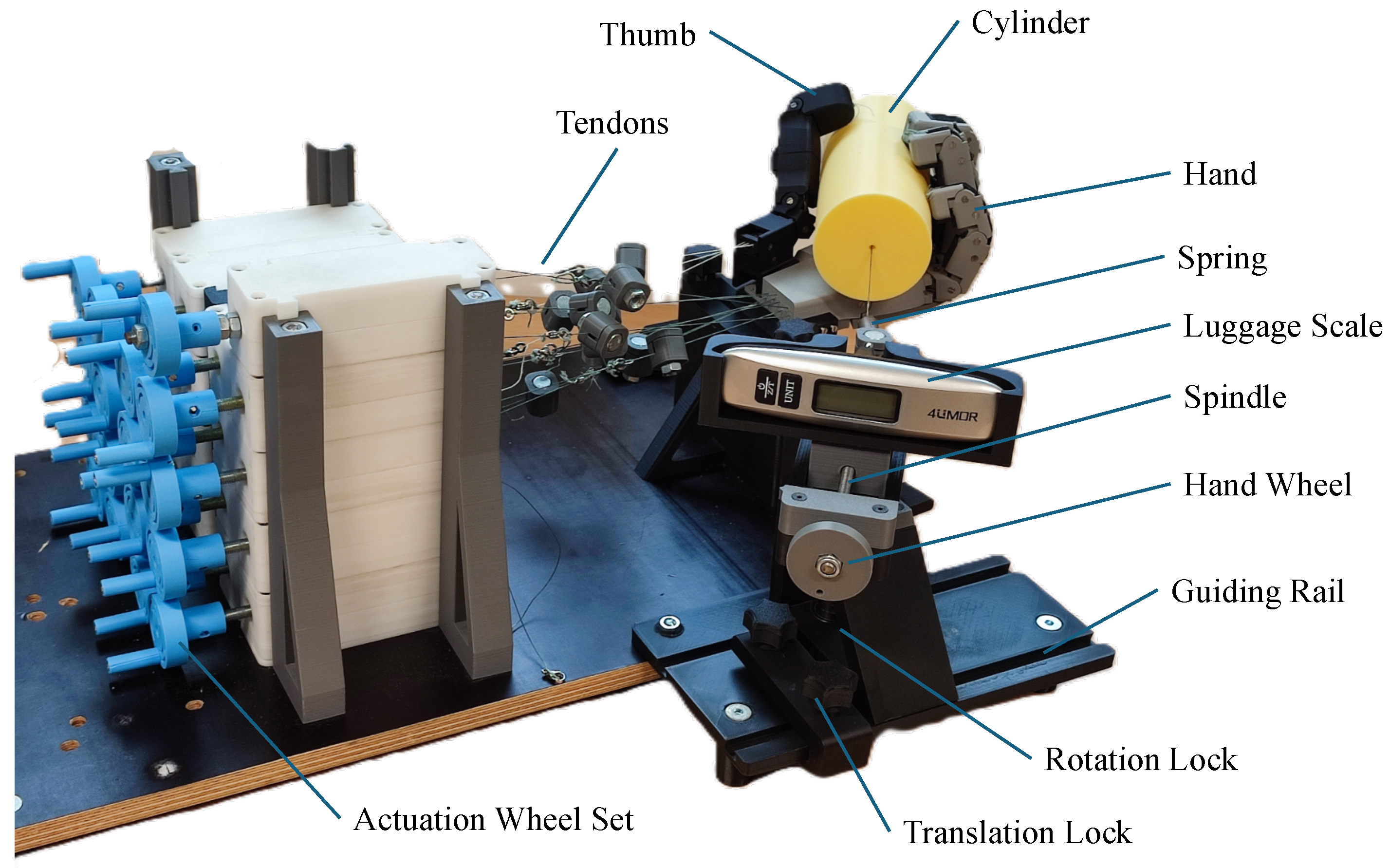
The manual test bench provided the experimental platform for assessing whether the main theoretical trends remained meaningful under practical hardware conditions. The setup was custom-built at the Institute of Mechanism Theory, Machine Dynamics and Robotics (IGMR), RWTH Aachen University (Aachen, Germany), by Sebastian Polzin and Daniel Gossen. Adopted from Gossen et al. [
17], it provided repeatable quasi-static tendon actuation by converting spindle rotation through lead-screw mechanisms into defined linear tendon displacement. The hand was mounted rigidly through a fixed adapter, while object placement and pull direction were kept consistent across tests. The controlled inputs were tendon-displacement set-points, and the measured outcomes included posture, contact state, and extraction force.
Figure 3 shows the setup. The tendon, spring, spindle, and guide components formed part of the inherited custom-built bench assembly. Effects related to tendon routing, displacement resolution, friction, seating, and hysteresis were retained as part of the experimental boundary conditions.
2.7.2. Experimental Validation Scope
The experimental evaluation served as a task-objective validation layer for selected reduced-DOF cases rather than as a complete hardware validation of all five theoretical configurations. Using the inherited manual test bench and shared palm-finger model from Gossen et al. [
17], the 2-1-1 and 2-0-1 thumb prototypes were evaluated through physical Kapandji assessment and cylindrical grasp testing. These configurations were selected because they provide a practically informative comparison between MCP articulation and MCP fixation, with 2-1-1 also representing the most frequently observed configuration in
Table 1. The experiments were therefore interpreted as a task-level consistency check for selected reduced-DOF trends, especially whether fixing the MCP joint preserved cylindrical grasp performance or introduced an earlier feasibility boundary. The modular setup preserved the thumb-only variation logic of the theoretical model, so experimental differences could be attributed mainly to the implemented thumb architecture.
2.7.3. Physical Opposition Evaluation
Physical opposition evaluation, based on the Kapandji Opposition Test (KOT) [
3], was used to test whether theoretically feasible opposition remained realizable in hardware. Using manual tendon actuation on the test bench, the complete 11-target KOT sequence was repeated three times for each tested thumb configuration. A point was counted as successful only if stable unsupported contact was achieved. The protocol deliberately retained friction, slack, compliance, hysteresis, and fabrication tolerances, so this metric served as the experimental counterpart to the qualitative opposition measure used in the theoretical evaluation.
2.7.4. Maximum Grasp Force Evaluation
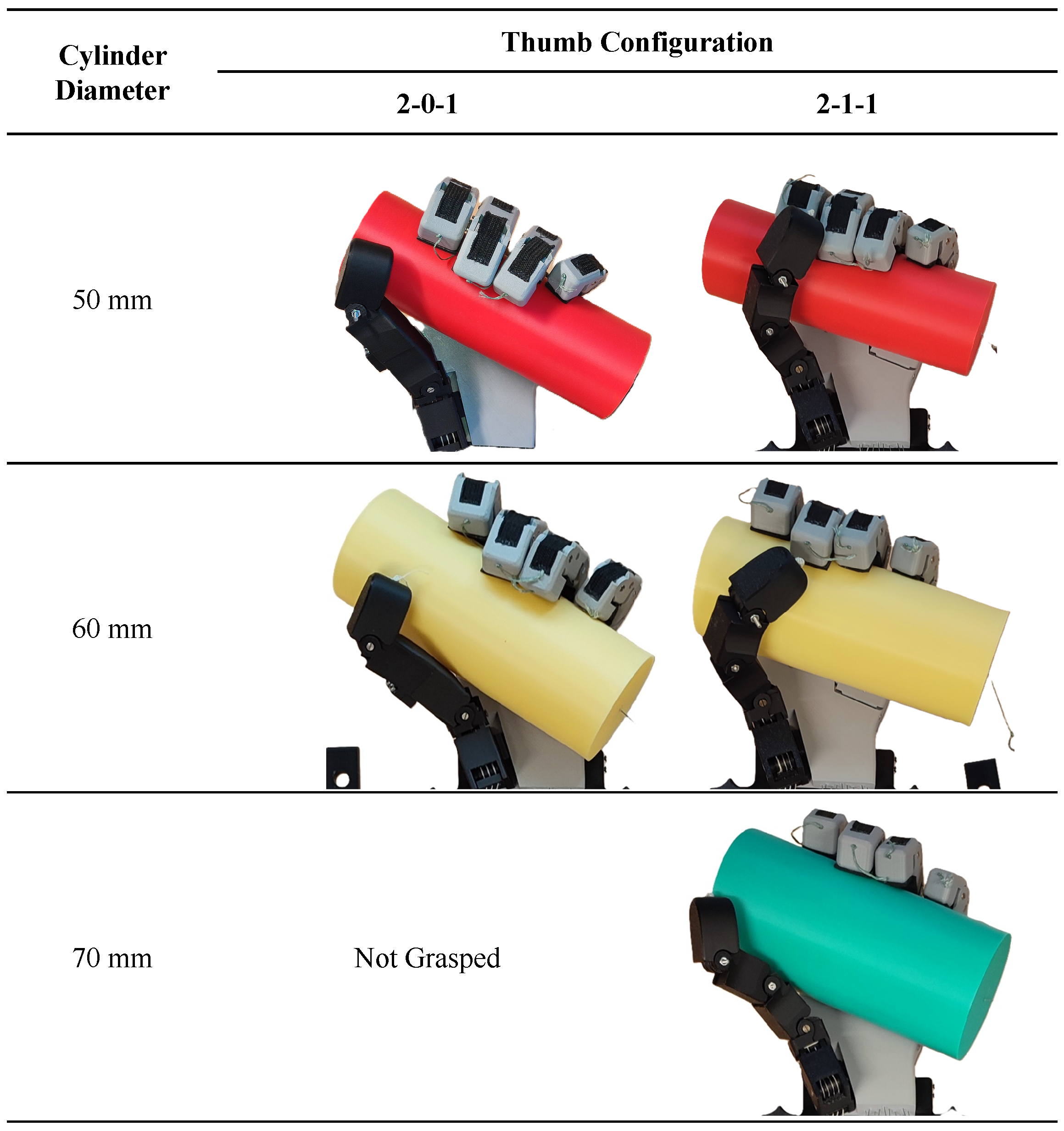
Maximum grasp pull-out force was measured to quantify grasp retention under quasi-static axial loading for the selected reduced-DOF prototypes. Rigid cylinders of 5, 6, and 7 cm diameter were used, with the 6 cm cylinder reproducing the nominal theoretical reference object from
Section 2.5.3 and the 5 and 7 cm cylinders probing grasp behavior below and above that reference size. Each trial required a stable cylindrical grasp to be formed before quasi-static axial loading was applied until slip occurred, following Gossen et al. [
17] with minor modifications, as presented in
Table A3.
Each valid thumb-cylinder pair was tested in three repeated pull-out trials. In each trial, the grasp was reformed, quasi-static axial loading was applied until slip occurred, and the peak mass value recorded by a digital hanging luggage scale (4UMOR (Shenzhen, China); capacity: 50 kg; resolution: 10 g) was taken as the trial maximum. The three peak mass values were converted to force using Equation (
15). The reported maximum grasp force was calculated as the mean of the three converted peak force values, and the sample standard deviation was used to describe trial-to-trial variability. Because only
trials were available for each valid condition, the experimental comparison was treated as a descriptive repeatability assessment rather than as a basis for formal inferential statistical testing. Accordingly, the force results were used to describe observed repeatability and feasibility trends, not to establish statistically significant differences between thumb configurations. For the 2-0-1 thumb with the 7 cm cylinder, no stable initial grasp could be formed; therefore, this condition was excluded from force measurement.
Maximum grasp force, also termed maximum pull-out axial force, was computed from the peak mass reading of the luggage scale as
where
is the peak measured mass in grams and
g is the gravitational acceleration. Higher pull-out force values were interpreted as stronger grasp retention under the applied loading condition.
Measurement uncertainty was estimated from the luggage-scale resolution and trial-to-trial variability. The luggage scale had a mass resolution of
, giving a standard uncertainty of
under a rectangular error distribution. After conversion using Equation (
15), this corresponds to a resolution-related standard force uncertainty of approximately
, or an expanded uncertainty of approximately
for
. This value represents only the scale-resolution contribution, while procedural repeatability effects from grasp re-formation, tendon settling, friction, alignment, and manual axial loading were represented by the sample standard deviation of the three repeated trials for each valid condition.
3. Results
This section reports the theoretical and experimental results in the same order as the evaluation framework defined in
Section 2.5 and
Section 2.7. It first presents the theoretical comparison across thumb configurations, then reports a local parameter sensitivity check for the main sampling and threshold parameters, and finally presents the targeted experimental validation of the reduced-DOF cases. The main theoretical results are summarized in
Table 2.
3.1. Opposition Results
Kapandji opposition scores remained high across the evaluated configurations, but the first reachability loss appeared in the most simplified thumb architecture. As shown in
Table 2, 3-1-1, 2-2-1, 2-1-1, and 2-0-1 each reached all 11/11 KOT targets, forming a qualitative tie under the classical pass-fail criterion. In contrast, 1-1-1 reached 10/11 targets and failed at the index-finger MCP target. Thus, binary opposition reachability was preserved across several reduced-DOF configurations, even though the most simplified serial architecture already showed a qualitative reachability limitation.
The KOT-inspired orientation mismatch differentiated configurations that remained tied under classical KOT reachability.
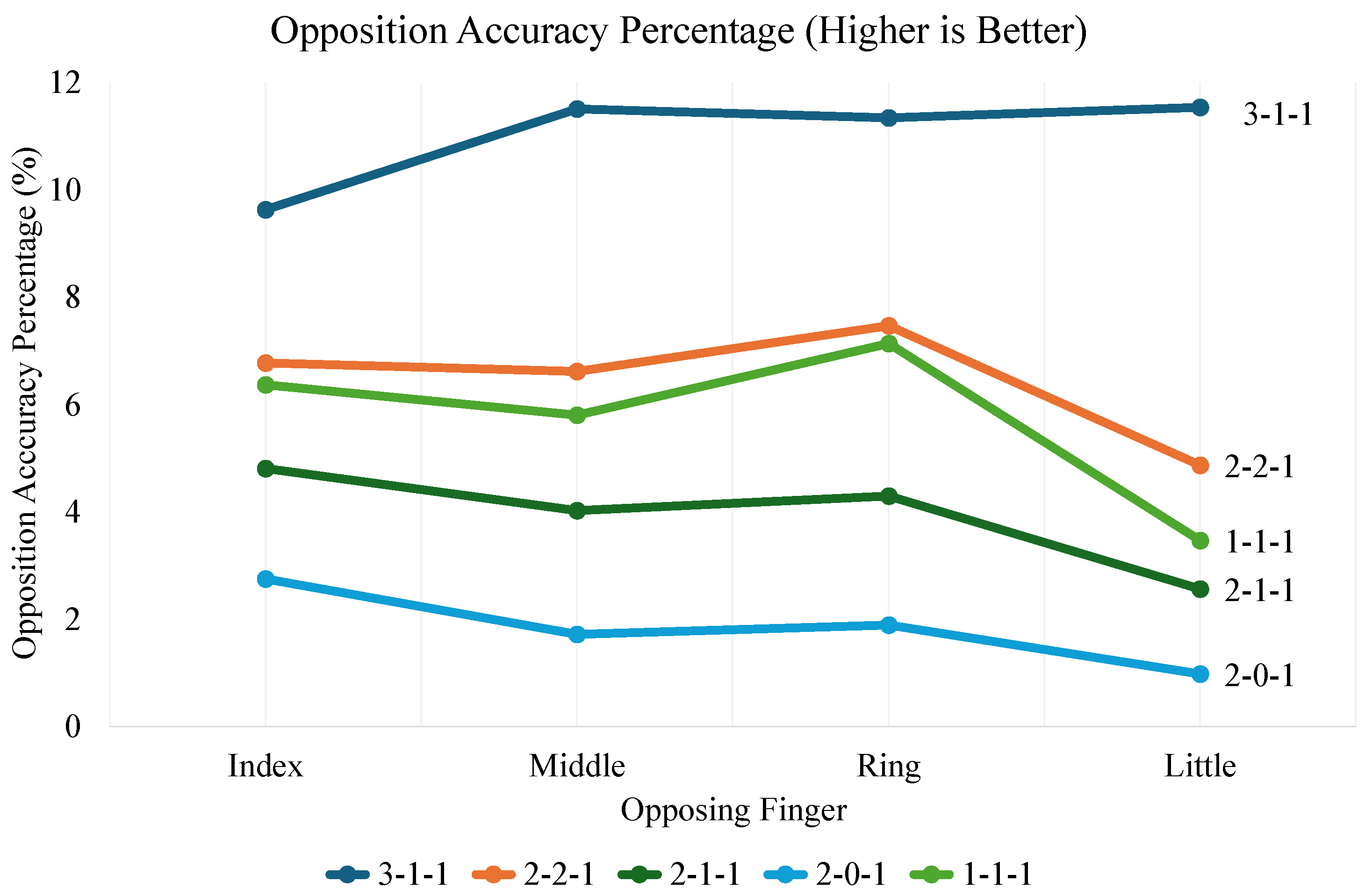
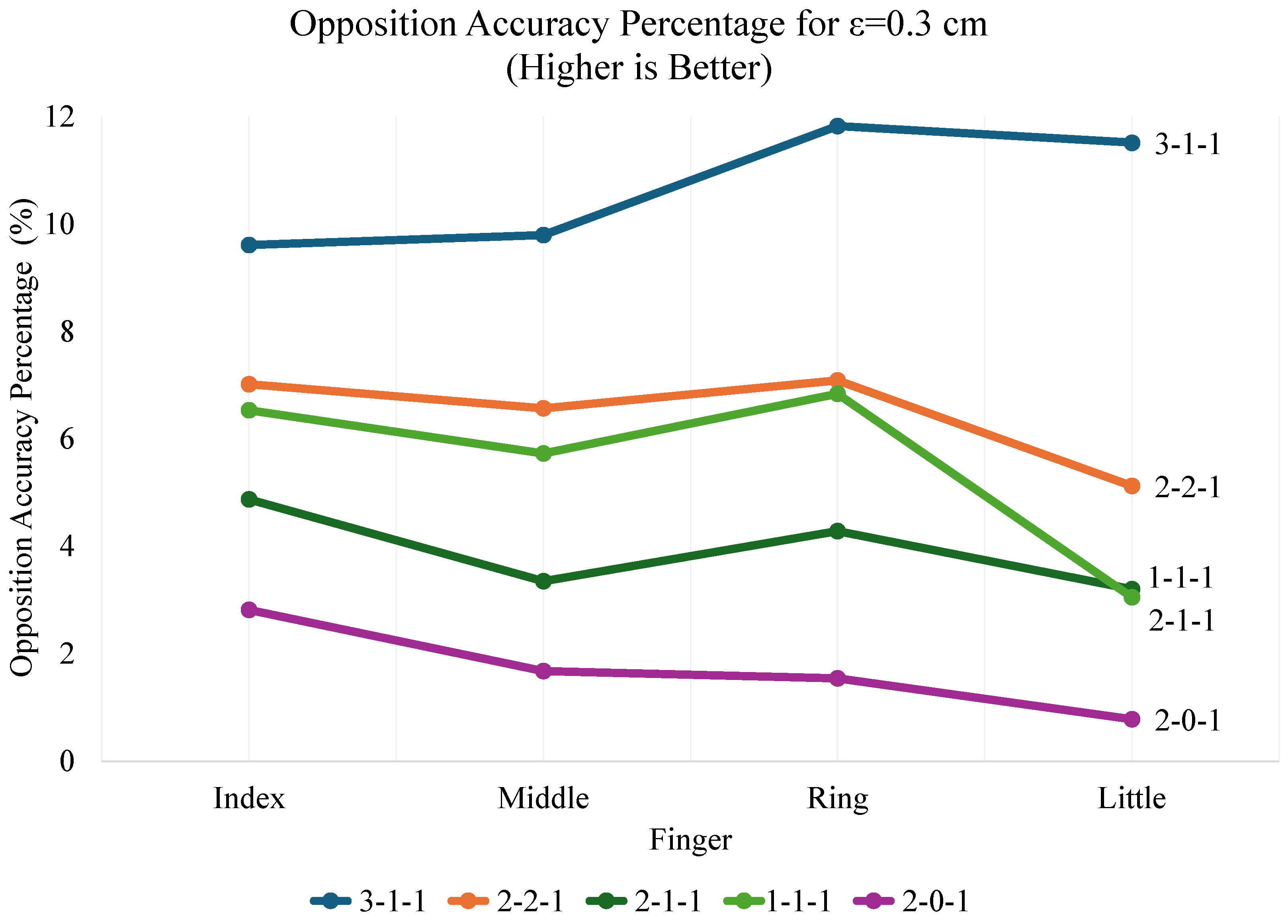
Figure 4 shows that 3-1-1 consistently achieved the strongest opposition accuracy across the index, middle, ring, and little fingertips, while reduced-DOF configurations generally shifted toward poorer orientation alignment. Across the compared configurations, the decreasing order of opposition accuracy was 3-1-1 > 2-2-1 > 1-1-1 > 2-1-1 > 2-0-1. This result shows that identical KOT scores did not imply equivalent opposition quality.
The combined KOT and mismatch-based results clarified where reachability and alignment diverged. The pairs 2-2-1 versus 2-1-1 and 2-1-1 versus 2-0-1 retained identical 11/11 KOT scores but lost opposition accuracy after MCP abduction–adduction removal and subsequent MCP fixation. Conversely, 1-1-1 missed one KOT target but still showed better orientation alignment than 2-1-1 and 2-0-1. Classical KOT, therefore, showed whether targets were reachable, while opposition accuracy showed how well those contacts were aligned. Practically, configurations with higher opposition accuracy were better able to bring the thumb and opposing fingertips into mutually compatible orientations at near-contact poses, whereas configurations with lower opposition accuracy were more likely to reach the same target region through oblique or less tip-aligned contact postures. The detailed numerical results for the orientation mismatch metric, median values, and opposition accuracy are shown in
Table A4.
3.2. Workspace Volume and Compactness Results
Workspace volume decreased sharply as thumb DOFs were removed or fixed, revealing quantitative losses that were not visible in the qualitative KOT tie.
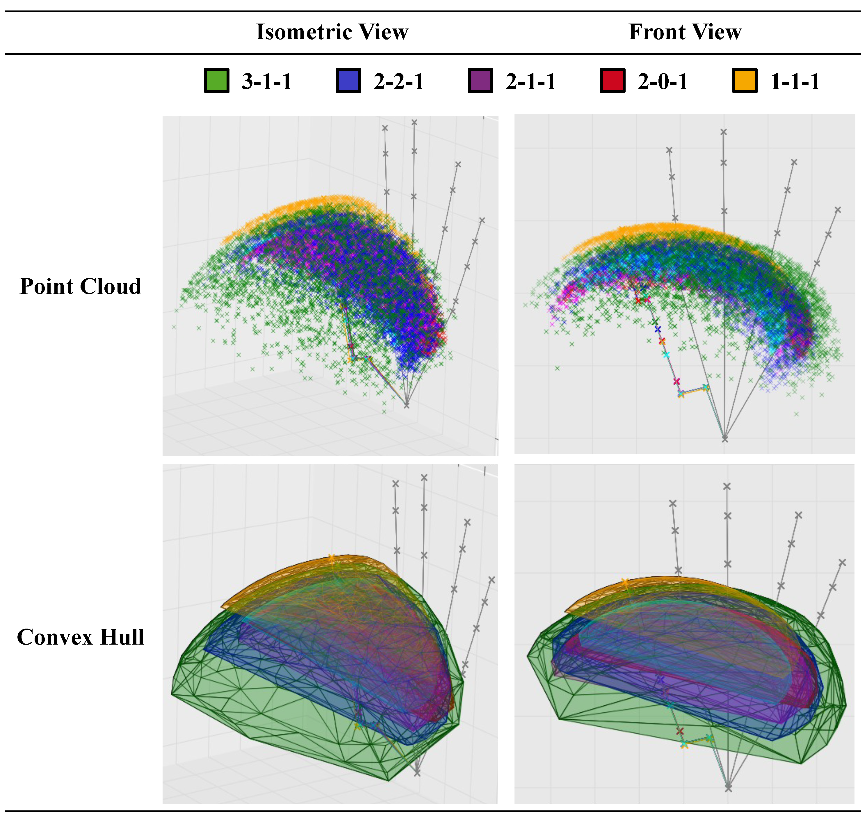
Figure A5 shows the largest convex-hull task-space volume for 3-1-1 at 979.75 cm
3, followed by 2-2-1, 2-1-1, 1-1-1, and 2-0-1. Because these values were obtained from convex-hull volumes, they should be read as comparative upper-bound estimates of reachable thumb-tip space rather than exact measurements of non-convex workspace geometry. The transition from 3-1-1 to 2-2-1 nearly halved reachable volume, while the transition from 2-2-1 to 2-1-1 produced the largest stepwise loss among the main articulated configurations. The lower volume of 2-0-1 compared with 2-1-1 further showed that MCP fixation reduced global coverage relative to the corresponding articulated MCP case.
Workspace compactness showed that the feasibility-restored 1-1-1 geometry did not translate into efficient reach retention. The compactness ranking was 3-1-1 > 2-2-1 > 2-1-1 > 2-0-1 > 1-1-1, meaning that DOF reduction generally decreased not only absolute reach but also reach efficiency relative to thumb size. Although 1-1-1 had a slightly larger convex-hull volume than 2-0-1, its lengthened and reoriented feasibility-restoration geometry increased the characteristic-length penalty and resulted in the weakest compactness value. Therefore, the 1-1-1 workspace and compactness results should be interpreted together rather than as independent indicators of retained function.
3.3. Grasp Opportunity and Best Grasp Pose Results
Grasp opportunity decreased strongly with thumb simplification and separated configurations that remained similar in KOT reachability. As shown in
Table 2, feasible grasp candidates around the reference cylinder decreased from 32 for 3-1-1 to 9 for 2-2-1 and 2-1-1, and 8 for 2-0-1, while 1-1-1 produced no feasible candidate grasps under the adopted constraints. This result shows that several configurations could still reach KOT targets while losing a substantial grasp-candidate margin for the cylindrical power-grasp task.
Best grasp pose feasibility further distinguished configurations by showing whether a valid cylinder grasp could be retained after the additional filtering and force-feasibility checks. The 3-1-1 and 2-2-1 configurations yielded valid best poses within the adopted filtering and optimization pipeline, whereas 2-1-1 and 2-0-1 remained closer to the feasibility boundary despite retaining feasible candidate grasps. The 1-1-1 configuration produced no feasible candidate grasp and therefore no valid best pose.
Figure A6 shows the best grasp pose for all configurations and should be interpreted together with the candidate-grasp counts.
3.4. Kinematic Dexterity Results
Kinematic dexterity produced a ranking related to, but distinct from, workspace performance. As summarized in
Table 2 and visualized in
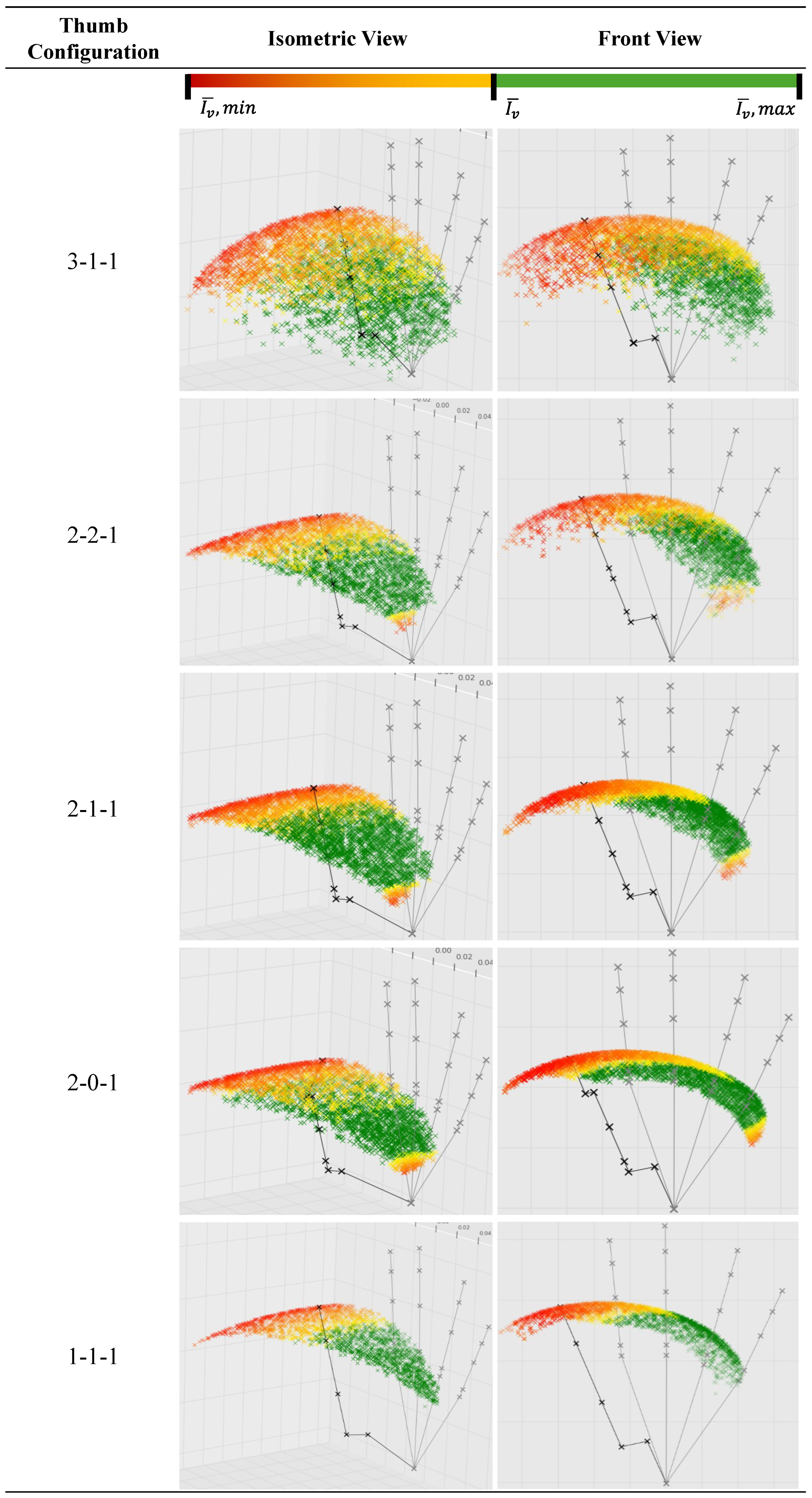
Figure A7, the mean Jacobian matrix condition number (JMCN; lower is better) and mean isotropy index (
; higher is better) both identified 2-2-1 as the best-conditioned configuration and 1-1-1 as the weakest configuration. Thus, the configuration with the largest workspace was not automatically the best-conditioned one.
The reduced-DOF configurations showed small but important differences between the two dexterity indices. Moving from 3-1-1 to 2-2-1 improved both mean JMCN and mean , indicating more uniform local motion-force transmission within the retained workspace. Removing MCP abduction–adduction in 2-1-1 reduced isotropy relative to 2-2-1, while MCP fixation in 2-0-1 produced a similar mean JMCN to 2-1-1 but a lower mean . Therefore, 2-1-1 and 2-0-1 should be interpreted as closely related in mean conditioning, with 2-1-1 retaining slightly better isotropy and 2-0-1 showing a marginally lower JMCN in the reported mean values.
3.5. Local Parameter Sensitivity Check
A local parameter sensitivity check was performed to examine whether the main theoretical trends depended strongly on the selected sampling and threshold values.
The workspace volume (
) trend remained stable under variation of the sampling count
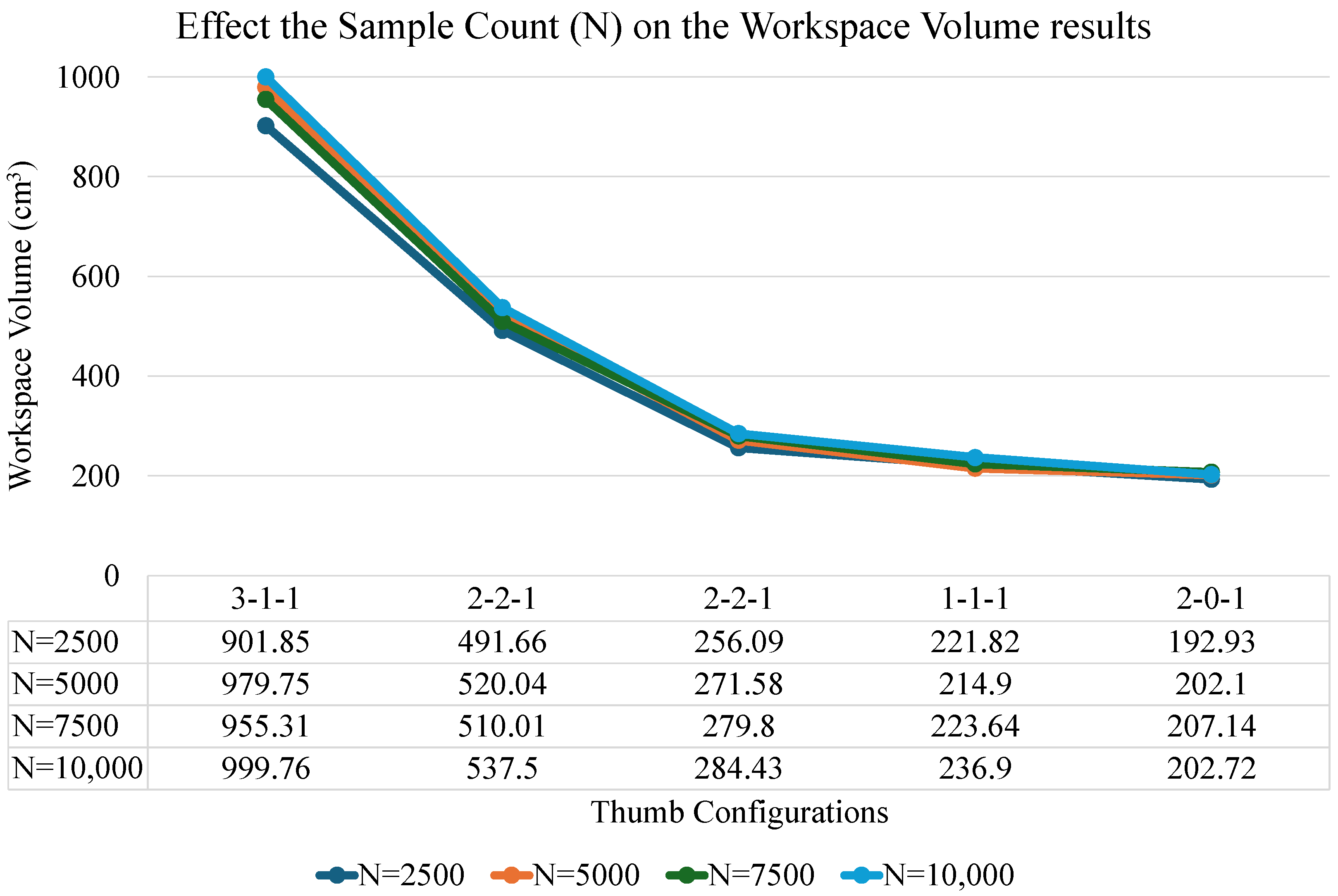
N. The convex-hull workspace volume was recalculated for
, 5000, 7500, and 10,000 sampled poses. The result graph is shown in
Figure A8. Although the absolute workspace volumes changed with sampling density, the main configuration-level trend remained unchanged across the tested sample counts. In all cases, 3-1-1 produced the largest workspace volume, followed by the reduced-complexity configurations. This result indicates that the main workspace volume interpretation was not caused by the selected baseline value of
.
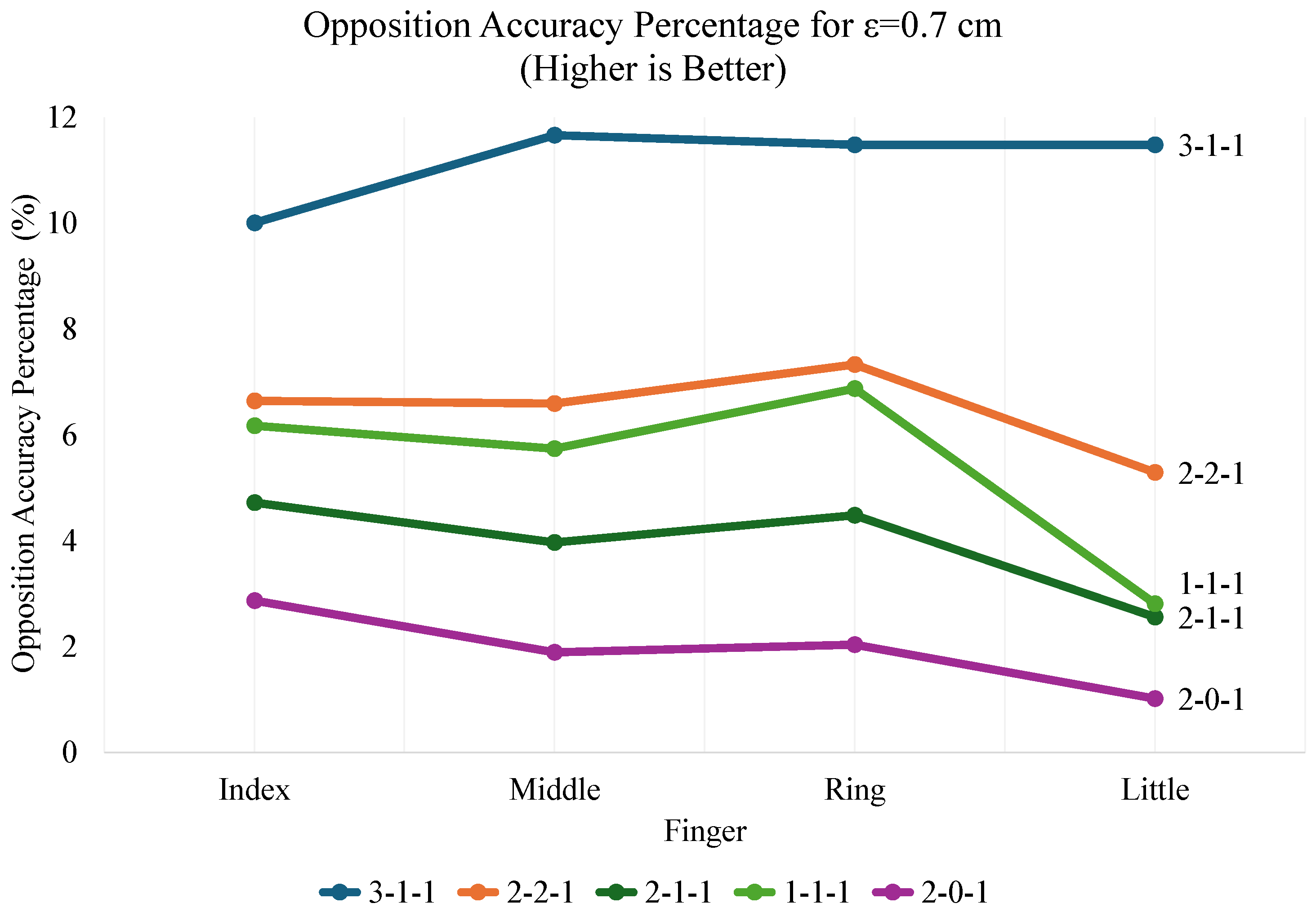
The opposition accuracy trend also remained broadly stable under variation of the proximity threshold
. The opposition analysis was repeated for
,
, and
cm. The results for the two extrema are shown in
Figure A9 and
Figure A10. Changing
affected the retained near-contact candidate set and therefore changed the exact opposition accuracy values, but the main comparative interpretation remained consistent across the tested thresholds. In particular, 3-1-1 retained the strongest opposition accuracy, while 2-0-1 remained the weakest configuration in this metric. This behavior indicates that the alignment-based conclusion was not dependent solely on the baseline value of
cm.
The candidate-grasp count results remained stable under variation of the cylinder-contact threshold
, although the exact candidate counts were threshold-dependent. As expected,
was directly related to the number of retained candidate grasps. However, the main interpretation was unchanged: 3-1-1 retained the largest grasp-candidate margin, while 1-1-1 produced no feasible candidate grasps under any tested threshold. The close values of 2-2-1 and 2-1-1 indicate that their exact candidate-grasp counts are locally threshold-sensitive, but this does not change the broader conclusion that both configurations provide substantially smaller grasp margins than 3-1-1.
Table 3 summarizes the sensitivity of candidate grasp count to
.
Overall, the local sensitivity check showed that the exact numerical values of the threshold-dependent outputs should be interpreted within the adopted parameter setting. However, the main configuration-level trends for workspace volume, opposition accuracy, and candidate grasp count remained consistent under the tested local parameter variations. The primary comparative conclusions were therefore not driven solely by the selected baseline values of N, , and .
3.6. Equal-Weight Scorecard for Theoretical Results
The equal-weight scorecard provided a compact baseline synthesis of the theoretical results across all evaluated thumb configurations. As shown in
Table 4, the aggregate order under the adopted scoring logic was 3-1-1, 2-2-1, 2-1-1, 2-0-1, and 1-1-1. This result confirmed the metric-level trend that 3-1-1 retained the strongest overall capability envelope, while 2-2-1 was the strongest reduced-complexity alternative.
The aggregate ranking should be interpreted as a theoretical synthesis, not as uniform superiority across all metrics. For example, 2-2-1 achieved the best dexterity values, whereas 3-1-1 remained stronger in workspace volume, compactness, and grasp opportunity. The scorecard also included only the theoretical metrics defined in
Section 2.5; experimental measurements were excluded because equivalent hardware results were not available for all five configurations.
3.7. Experimental Evaluation Results
The experimental evaluation was performed on prototypes of the 2-1-1 and 2-0-1 thumb configurations, and the results are summarized in
Table 5. The physical Kapandji Opposition Test (KOT) was repeated three times per thumb configuration, while the maximum grasp-force test was repeated three times for each valid thumb-cylinder pair.
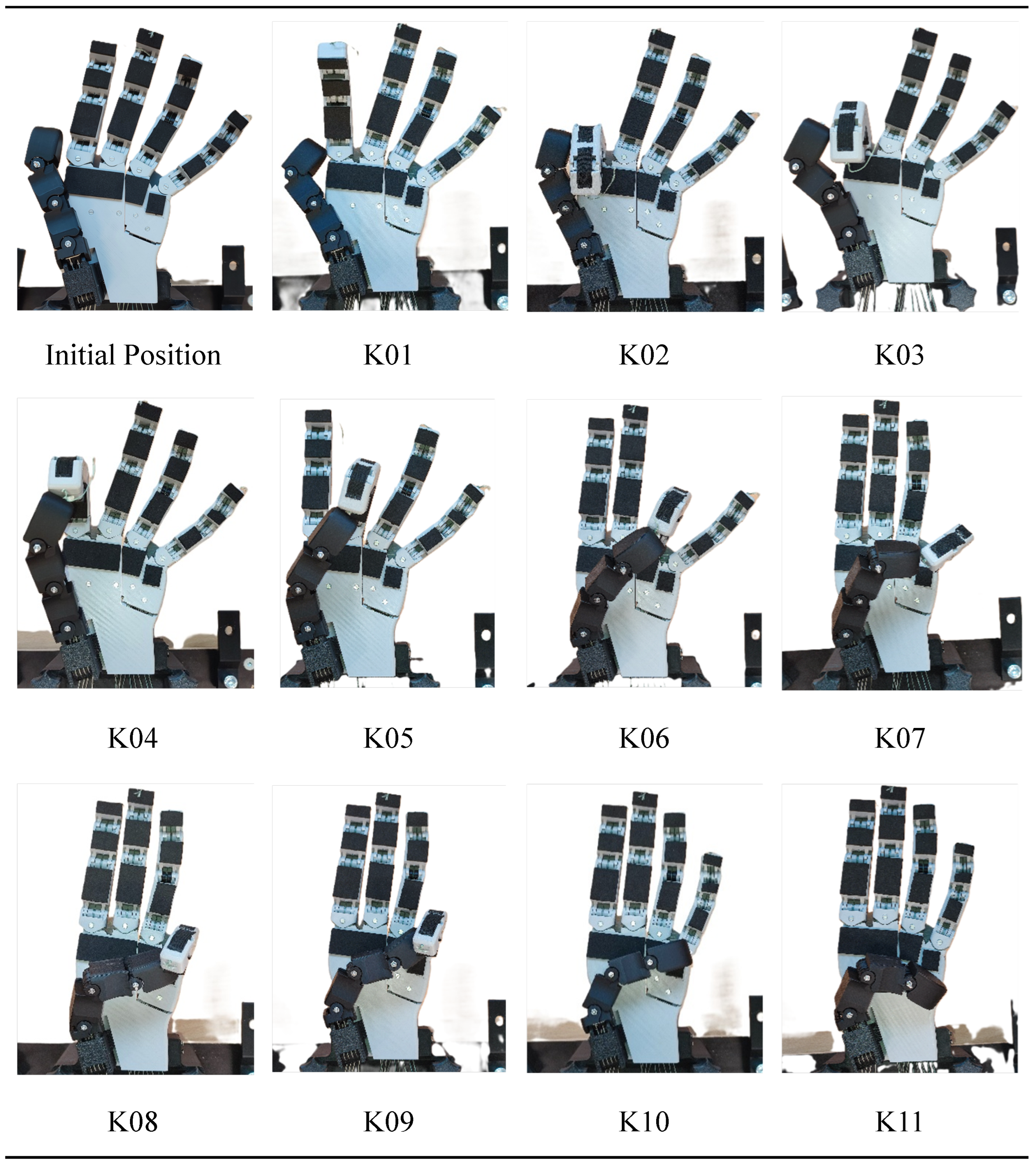
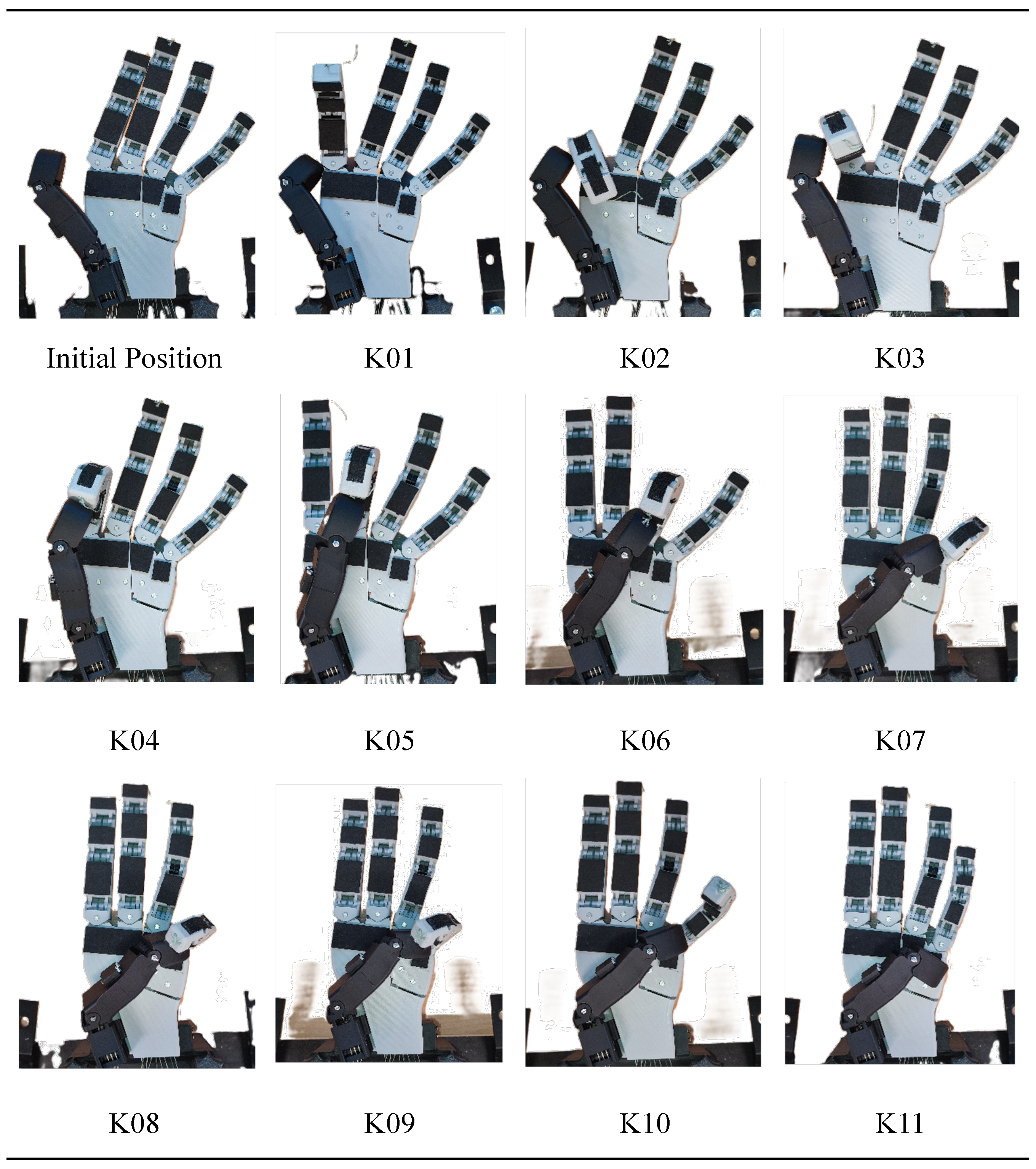
The physical KOT result was repeatable across the three complete test repetitions for both tested thumb configurations. The 2-1-1 and 2-0-1 prototypes each achieved 11/11 targets in all three repetitions, indicating that the binary opposition outcome was not trial-dependent under the adopted bench procedure. The corresponding observations are shown in
Figure A11 and
Figure A12, and the detailed results are compiled in
Table A5. Thus, MCP fixation did not change the binary KOT outcome for the implemented prototype pair. However, visual inspection showed that identical scores did not imply ideal contact formation, since both prototypes often reached targets through non-ideal terminal or lateral contact rather than well-aligned human-like oppositional contacts.
The maximum grasp-force experiment showed similar performance for both configurations at smaller cylinder diameters, but a clear feasibility split at the largest diameter. For each valid thumb-cylinder pair, three repeated pull-out trials were performed, and
Table 5 reports the mean and sample standard deviation of the resulting peak pull-out forces. The reported standard deviations, therefore, represent the repeatability of the complete manual pull-out procedure, rather than the luggage-scale resolution alone. At 5 and 6 cm, 2-1-1 and 2-0-1 produced similar mean peak pull-out forces, and their mean ± sample-standard-deviation ranges overlapped, as summarized in
Table 5 and illustrated in
Figure A13. These results were therefore interpreted descriptively as showing no clear force-level separation within the observed trial-to-trial variability, rather than as a statistically tested equivalence between the configurations. At 7 cm, the comparison was not a force-level statistical comparison but a feasibility outcome: only 2-1-1 formed a stable initial grasp, while 2-0-1 failed the stability gate and was therefore not evaluated in the pull-out force test. These experimental results supported the same overall comparative trend indicated by the theoretical results, namely that both configurations remained viable for smaller cylindrical grasps, while the fixed-MCP variant reached its feasibility boundary earlier as task demand increased. This agreement should be interpreted as a task-level consistency check for the restricted cylindrical grasp setup and the selected reduced-DOF thumb pair, rather than as a direct experimental validation of all theoretical metrics across all five configurations.
4. Discussion
This section interprets the reported results from scorecard-based, priority-dependent, and design-oriented perspectives. It first synthesizes the theoretical ranking, then discusses cross-metric trade-offs, and finally translates the findings into practical implications for thumb DOF selection.
4.1. Equal-Weight Scorecard Interpretation
The equal-weight scorecard reinforces the main finding that qualitative thumb opposability alone is insufficient for comparative thumb assessment. Although several configurations appeared similar under classical Kapandji reachability, the combined theoretical score separated them clearly once opposition alignment, workspace, compactness, grasp opportunity, and dexterity were considered together. Under this baseline synthesis, 3-1-1 provided the broadest overall capability envelope, while 2-2-1 emerged as the strongest reduced-complexity alternative.
This baseline synthesis is most informative when read as a compact summary of how the five configurations differ once the individual metric trends are considered together. The scorecard should not be interpreted as a universal design prescription. Its aggregate order depends on equal weighting across distinct metric families and on the conversion of continuous outcomes into ordinal score bands. Different robotic-hand applications may prioritize workspace, dexterity, contact alignment, actuation simplicity, or grasp opportunity differently, so final design decisions should be based on the priority-dependent interpretation developed in the following subsection. In this sense, the scorecard supports the broader argument of the paper that qualitative opposability alone is insufficient for comparative thumb assessment.
4.2. Design-Priority Interpretation of Cross-Metric Differences
Practical thumb selection depends on the application priority rather than on the equal-weight scorecard alone. In real robot-hand applications, different tasks prioritize different capability dimensions, so the most suitable thumb design depends on whether dexterity, pinch alignment, grasp robustness, or actuation simplicity is emphasized. The discussion, therefore, shifts here from aggregate ranking to design-priority interpretation, in which cross-metric differences are read in relation to the intended use case rather than collapsed into one universal order.
Table 6 translates the cross-metric differences between thumb configurations into application-specific primary and secondary configuration choices. For general-purpose dexterity and manipulation, 2-2-1 emerges as the strongest primary choice because it combines the best mean dexterity with reduced design complexity, while 3-1-1 remains the strongest secondary choice when additional CMC freedom is acceptable. For precision pinch emphasis, 3-1-1 becomes the primary choice because it provides the strongest overall performance together with the best opposition accuracy, whereas 2-2-1 remains the closest reduced-complexity alternative. For power grasp and enclosure robustness, 3-1-1 again offers the highest grasp-candidate margin, while 2-1-1 or 2-2-1 may serve as practical secondary options depending on whether simplicity or additional grasp margin is prioritized. Finally, for minimal actuation with task-specific retention, 2-0-1 provides the most useful compromise because it preserves grasping within a narrow task envelope, whereas 1-1-1 should be interpreted only as an extreme minimum-actuation reference with substantially reduced retained function. In this form, the table does not claim one universally best configuration; instead, it shows how the preferred thumb design changes once the intended application determines which performance criterion matters most.
4.3. Design Implications Based on DOF Relevance
The design implications of the present study are best understood from how specific DOF redistributions, removals, and fixations changed performance across the evaluated thumb configurations. The transition from 3-1-1 to 2-2-1 showed that reducing CMC mobility lowered workspace, compactness, and grasp-candidate abundance, even though 2-2-1 remained the strongest reduced-complexity alternative and achieved the best mean dexterity. This suggests that two active CMC motions can preserve much of the retained thumb function, but that the third CMC DOF still contributes substantially to global reach and grasp-candidate margin. The transition from 2-2-1 to 2-1-1 further showed that removing MCP abduction–adduction did not eliminate qualitative opposition, but reduced posture versatility, opposition alignment, workspace, and dexterity.
The largest simplification penalties appeared when active MCP actuation was removed entirely or when the thumb was reduced to an extreme serial architecture. The transition from 2-1-1 to 2-0-1 showed that MCP fixation can preserve task-specific objectives like cylindrical grasp outcomes at smaller diameters, but at the cost of reduced workspace, weaker alignment, and an earlier feasibility boundary at the largest tested diameter. Because the performance of 2-0-1 depends on the selected fixed MCP posture [
29], fixation should be treated as a task-specific compromise rather than as equivalent to an articulated MCP joint. A further reduction to 1-1-1 produced the broadest loss of retained function, including reduced KOT reachability, poor compactness, zero feasible candidate grasps, and strongly degraded dexterity.
The interpretation of strongly simplified thumb configurations must account for geometry-specific adaptations as well as nominal DOF count. For the 1-1-1 configuration, the increased thumb length and reoriented base improved minimum opposition feasibility, but these changes also affected workspace volume and the characteristic-length normalization used in the compactness metric. Therefore, the 1-1-1 results should be read as the combined effect of minimal DOF allocation and the geometry required to make this reduced-DOF representative feasible within the shared hand model. More generally, these effects should be interpreted as configuration-level effects rather than isolated DOF-count effects, because reduced-DOF thumb designs may require fixed joint postures, altered segment lengths, or modified base orientations to remain feasible in a given hand architecture.
The targeted experiments supported these design implications by showing that both 2-1-1 and 2-0-1 remained viable for smaller cylindrical grasps, while the fixed-MCP 2-0-1 configuration reached its feasibility boundary earlier as object diameter increased. These observations provide a task-level consistency check for the selected reduced-DOF pair, not a complete experimental transfer of all theoretical metrics.
Table 7 summarizes the observed effects of specific DOF redistributions, removals, and fixations across the theoretical and experimental results.
4.4. Limitations to Validity and Transferability of Results
The present results should be interpreted as a controlled comparative study under specific modeling, geometric, and task assumptions rather than as universally transferable performance bounds. The shared workspace sampling procedure, assumed ROM limits, common hand-level boundary conditions, and cylinder-centered grasp task were necessary to preserve comparability across thumb configurations. However, these choices also limit the direct transfer of the exact numerical values and task-specific rankings to other hand geometries, object classes, actuation systems, or manipulation scenarios. The theoretical results are therefore most meaningful as relative comparisons under shared assumptions, not as absolute measures of isolated configuration quality. For example, the improved mean dexterity of 2-2-1 relative to 3-1-1 does not imply universal superiority, because the smaller workspace of 2-2-1 may exclude low-dexterity regions that remain present in the broader workspace of 3-1-1.
The convex-hull approximation limits the geometric accuracy of the workspace-based results. Since the convex hull encloses all sampled thumb-tip positions within the smallest convex polytope, it can include regions that are not actually reachable when the true workspace is non-convex or locally disconnected. The reported workspace volumes should therefore be interpreted as comparative upper-bound estimates rather than exact reconstructions of reachable thumb-tip space. This limitation also affects workspace compactness, because compactness is directly derived from convex-hull volume. Nevertheless, all configurations were evaluated using the same approximation, so the large relative reductions from 3-1-1 to the reduced-DOF configurations are unlikely to be caused by convex-hull overestimation alone. Close comparisons between reduced-complexity configurations with similar workspace volumes should still be interpreted cautiously. Future work should replace or complement the convex-hull proxy with alpha-shape-based workspace reconstruction, as discussed by Llop-Harillo et al. [
33], to better preserve non-convex workspace boundaries.
Thumb DOF allocation and thumb geometry could not be completely separated for all reduced-complexity configurations. Although the palm, non-thumb fingers, reference frames, task definitions, and evaluation pipeline were kept fixed, some thumb variants required geometry-specific adaptations to remain feasible within the shared hand model. In particular, the 1-1-1 configuration required base-twist and length adjustments to recover minimum qualitative opposition, while the 2-0-1 configuration used a fixed MCP posture rather than an actively articulated MCP joint. These choices may influence workspace volume, compactness, opposition alignment, and grasp feasibility in addition to nominal DOF allocation. The results should therefore be interpreted as comparisons of feasible representative thumb configurations under common boundary conditions, not as a perfectly isolated decomposition of DOF count and geometry.
The opposition metrics are simplified kinematic proxies rather than complete physical measures of opposability. The classical Kapandji Opposition Test is intentionally coarse and binary, since it indicates whether anatomical targets are reachable but does not distinguish contact quality, tip-to-tip alignment, or posture usability. Likewise, the KOT-inspired mismatch in Equation (
6) uses the Frobenius norm between rotation matrices and therefore captures the magnitude of relative orientation mismatch, but not the axis-specific contact direction or the physical contact state. Different relative orientations may therefore produce the same mismatch value even when only one corresponds to physically meaningful opposition. The mismatch metric should be read as a comparative indicator of orientation compatibility, not as a grasp-quality measure. It does not include contact patch geometry, compliance, friction, force closure, or object-level grasp stability. Future work should compare this proxy with quaternion-based or geodesic orientation metrics [
33].
The theoretical outputs also depend on algorithmic parameter choices and scorecard assumptions. The sample count
N, opposition threshold
, and cylinder-contact threshold
influence the exact numerical values of workspace, opposition, and grasp-candidate outputs. The local sensitivity check in
Section 3.5 showed that the main configuration-level trends remained stable under the tested local variations, but it did not cover repeated random seeds, broader parameter ranges, alternative object poses, parameter interactions, or uncertainty propagation across the scorecard. The equal-weight scorecard should therefore be interpreted only as a baseline comparative synthesis, not as a universal design prescription.
The experimental validation is limited by its restricted scope and manual tendon-driven implementation. Only the 2-1-1 and 2-0-1 prototypes were tested experimentally, so the hardware results provide a targeted task-level consistency check rather than a complete validation of all theoretical metrics or all five thumb configurations. The validation was also restricted to quasi-static Kapandji assessment and cylindrical pull-out tasks. The luggage scale introduced finite-resolution uncertainty, while the manual pull-out procedure introduced variability through grasp re-formation, tendon settling, friction, contact formation, spindle adjustment, and loading alignment. Although three repeated trials were used for each valid condition and the results were reported as mean ± sample standard deviation, the small sample size and manual actuation limit statistical strength. No formal significance testing was therefore used; the force results were interpreted as descriptive repeatability evidence, while the 7 cm case was treated as a feasibility outcome rather than a statistically tested force difference.
5. Conclusions
This study showed that qualitative thumb opposability alone is insufficient for comparing anthropomorphic robot thumb configurations. Although several configurations achieved identical 11/11 Kapandji scores, they differed clearly in opposition alignment, workspace volume, workspace compactness, grasp opportunity, and Jacobian-based dexterity. The results indicate that retained performance depends more on where mobility is preserved than on the total number of remaining DOFs. Overall, 3-1-1 provided the strongest overall capability envelope, while 2-2-1 emerged as the strongest reduced-complexity alternative and achieved the best mean dexterity. The results also showed that thumb simplification should prioritize functionally important mobility rather than DOF reduction alone. CMC mobility should be preserved first because it strongly affects global reach and grasp-candidate margin. Active MCP shaping should be retained when broader manipulation and posture versatility are required, whereas MCP fixation should be treated as a task-specific compromise for narrower grasp families. The targeted experiments supported this interpretation for the selected reduced-DOF pair: both 2-1-1 and 2-0-1 remained viable for smaller cylindrical grasps, but the fixed-MCP 2-0-1 configuration reached its feasibility boundary earlier at the largest tested diameter. Future work should extend the framework toward broader object sets, additional physical prototypes, larger experimental trial numbers, formal statistical testing, and more automated dynamic validation. Methodological extensions should include alpha-shape-based workspace reconstruction, more physically meaningful orientation metrics such as quaternion-based or geodesic measures, and expanded sensitivity analysis across sampling density, proximity thresholds, object poses, and uncertainty propagation.




 ,
,