Review

Underwater Polarized Light Navigation: Current Progress, Key Challenges, and Future Perspectives

Department of Mechanical Engineering, University of Shanghai for Science and Technology, Shanghai 200093, China
*
Author to whom correspondence should be addressed.
Robotics 2025, 14(8), 104; https://doi.org/10.3390/robotics14080104
Submission received: 15 May 2025 / Revised: 17 July 2025 / Accepted: 28 July 2025 / Published: 29 July 2025
(This article belongs to the Section Sensors and Control in Robotics)

Abstract

Underwater navigation remains constrained by technological limitations, driving the exploration of alternative approaches such as polarized light-based systems. This review systematically examines advances in polarized navigation from three perspectives. First, the principles of atmospheric polarization navigation are analyzed, with their operational mechanisms, advantages, and inherent constraints dissected. Second, innovations in bionic polarization multi-sensor fusion positioning are consolidated, highlighting progress beyond conventional heading-direction extraction. Third, emerging underwater polarization navigation techniques are critically evaluated, revealing that current methods predominantly adapt atmospheric frameworks enhanced by advanced filtering to mitigate underwater interference. A comprehensive synthesis of underwater polarization modeling methodologies is provided, categorizing physical, data-driven, and hybrid approaches. Through rigorous analysis of studies, three persistent barriers are identified: (1) inadequate polarization pattern modeling under dynamic cross-media conditions; (2) insufficient robustness against turbidity-induced noise; (3) immature integration of polarization vision with sonar/IMU (Inertial Measurement Unit) sensing. Targeted research directions are proposed, including adaptive deep learning models, multi-spectral polarization sensing, and bio-inspired sensor fusion architectures. These insights establish a roadmap for developing reliable underwater navigation systems that transcend current technological boundaries.

1. Introduction

The autonomous underwater vehicle (AUV) has been widely applied in various fields due to its excellent flexibility, mobility, and broad range of applications. In the civil field, AUVs play a crucial role in marine resource exploration, search and rescue operations at sea, as well as structural inspections of marine engineering structures, among other applications. In the military field, their application scope covers mine detection, underwater military confrontation, and other key tasks. However, the positioning technology of AUVs is still the main bottleneck restricting their further development, and in recent years, underwater navigation and positioning technology have been the hot spot of research [1,2]. With the continuous development of marine resources by human beings, higher requirements for underwater navigation and localization have also been put forward. At the same time, the application of AUVs in the fields of underwater search and rescue, underwater operation, and military combat also puts forward higher requirements on the accuracy as well as reliability of navigation.
Underwater navigation has been extensively reviewed in recent literature [3,4,5], highlighting the persistent challenges in achieving reliable positioning. Current methodologies for underwater navigation and positioning are diverse but exhibit significant limitations. Inertial Navigation Systems (INSs), although widely used in subaquatic environments, are prone to error accumulation and drift, leading to a gradual degradation of positioning accuracy over time [6]. Global Navigation Satellite Systems (GNSSs) are largely ineffective underwater due to the rapid attenuation of electromagnetic waves in aqueous media. Acoustic positioning systems, while capable of extended operational ranges and higher precision, are hindered by high deployment costs and reliance on pre-installed base stations [7]. Geophysical field matching navigation requires high-precision prior maps, which are often difficult to obtain in practice [8]. Similarly, vision-based Simultaneous Localization and Mapping (SLAM) techniques face substantial limitations in underwater environments [9], where low visibility and turbidity severely degrade performance [10]. Underwater terrain aided navigation (TAN) is also a novel underwater navigation technology. This method acquires terrain data from various sensors and highlights different advantages depending on the selected algorithm, but there is still room for improvement in terms of accuracy, security, and practicality [11].
When conventional navigation technologies face limitations in subaquatic environments, innovative approaches inspired by biological adaptations offer promising alternatives. Marine organisms such as cephalopods [12], crustaceans [13], and fish species [14] exhibit remarkable long-distance navigation capabilities through polarized light perception. These species detect and interpret underwater polarization patterns—a biological mechanism that provides critical insights for developing bio-inspired navigation systems to circumvent traditional constraints. Notably, underwater polarized light shares directional characteristics with atmospheric polarized light and remains detectable at depths exceeding 200 m [15]. However, research on underwater polarized light navigation remains nascent compared to its atmospheric counterpart. Consequently, this review first synthesizes atmospheric polarization navigation frameworks, which serve as foundational models for underwater adaptations. Existing methods are analyzed through two dimensions: (1) polarized light measurement techniques and (2) bionic navigation strategies. Additionally, this work presents the systematic classification of underwater polarization modeling methodologies, categorizing them into physics-based, data-driven, and hybrid approaches. Three critical challenges are identified: (i) dynamic cross-media polarization pattern distortion, (ii) interference from turbidity-induced noise, and (iii) insufficient integration of multi-modal sensing (e.g., polarization vision with sonar/IMU). By contextualizing these limitations within the current research landscape, this review underscores the need for adaptive models and cross-disciplinary innovations to advance underwater navigation systems.

2. Atmospheric Polarization Navigation Technology

Figure 1 illustrates the temporal evolution of research output in polarized light navigation technology over 20 years (2004–2024). This quantitative analysis was conducted through a systematic literature search in the Web of Science (WOS) core database, utilizing the Boolean query TS = (“polarized light” AND “navigation”). The resultant bar chart reveals a steady increase in annual publication counts, with three distinct growth phases: an initial exploratory period (2004–2010, average 8.6 publications/year), accelerated development (2011–2018, 15.6 publications/year), and recent technological maturation (2019–2023, 26.2 publications/year). This trend underscores the growing recognition of polarization-based navigation as a critical methodology for overcoming limitations in conventional systems, particularly in GNSS-denied environments.
Figure 2 presents a keyword co-occurrence network map of polarized light navigation research, generated through a systematic bibliometric analysis using VOSviewer software 1.6.20. Based on 342 publications (2004–2024) with a minimum keyword occurrence threshold of 10, the network comprises 57 nodes and 573 conceptual links, where node size corresponds to term frequency, and link thickness indicates thematic relevance. Four distinct research clusters are identified:
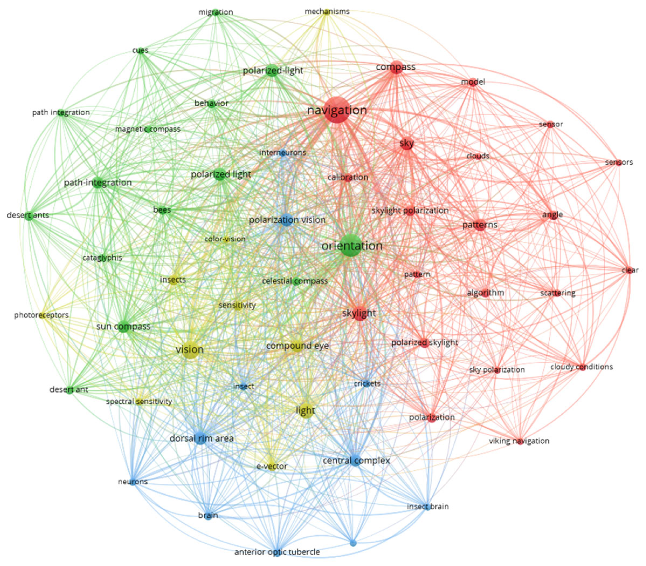
  • Navigation and Compass Systems (red cluster, 21 nodes): Centered on navigation and compass, this cluster integrates high-frequency terms such as skylight, sensors, and patterns, reflecting methodologies for celestial orientation and terrestrial navigation.
  • Polarized Light Navigation Technology (green cluster, 15 nodes): Focused on orientation and polarized light, key terms like path integration, celestial compass, and sun compass emphasize adaptive strategies for dynamic environmental navigation.
  • Polarized Light Sensing Mechanisms (yellow cluster, 10 nodes): Bridging hardware and biological principles, this cluster features vision, compound eye, and light, with subthemes including photoreceptors, sensitivity, and sensor mechanisms.
  • Polarization Vision Processing (blue cluster, 11 nodes): Highlighting neural and anatomical adaptations, terms such as dorsal rim area (a specialized region in insect eyes for polarization detection), neurons, and brain underscore post-sensory processing in biological polarization perception.
Figure 2. Keyword co-occurrence network map of polarized light navigation research.
Robotics 14 00104 g002
Core keywords (navigation, orientation, polarized light) exhibit the highest betweenness centrality, acting as interdisciplinary hubs that connect biological insights with technological innovations. This topology illustrates the field’s evolution from foundational studies of atmospheric polarization patterns to advanced bio-inspired navigation systems, emphasizing both theoretical models and practical implementations.
Under clear-sky conditions, sunlight scattered by atmospheric particles generates a structured polarization pattern, which is accurately described by the Rayleigh scattering model. Empirical and theoretical analyses of skylight polarization reveal three fundamental characteristics: (1) E-vector Orthogonality: The electric field vector (E-vector) orientation of polarized light maintains perpendicularity to both the solar and anti-solar meridians. (2) Solar Vector Relationship: At any atmospheric observation point, the E-vector direction remains orthogonal to the solar vector. (3) Symmetry Gradient: Polarization patterns exhibit mirror symmetry across the solar-anti-solar meridian plane. Rayleigh scattering theory predicts that under ideal conditions, the anti-solar hemisphere exhibits a polarization degree of 70–80% compared to 50–60% in the solar-aligned hemisphere—a relative difference of approximately 20% [16]. Field measurements in tropical marine environments corroborate this gradient, reporting 18–22% higher polarization degrees in the anti-solar region [15].

2.1. Point Source Polarization Navigation Technology

The development of point-source polarization navigation systems was initially inspired by the polarized light perception mechanisms observed in insects and other organisms. Early research focused on replicating biological compound eye structures through biomimetic sensor design, constrained by the technological limitations of the time.
Chu et al. [17] pioneered a point-source polarization sensor comprising three pairs of directional polarization analyzers arranged in a configuration analogous in principle to the schematic layout depicted in Figure 3a. Each analyzer pair consisted of orthogonally aligned polarizers offset by 60° relative to adjacent units: Unit 1: 0° and 90° polarizers; Unit 2: 60° and 150° polarizers; Unit 3: 120° and 210° polarizers. Photodiodes positioned behind each polarizer detected light intensity, with outputs fed into logarithmic ratio amplifiers to compute polarization parameters (Figure 3b). The sensor operated on key principles.
Taking the 0° polarizer as the reference coordinate system and assuming that the angle between the E-vector direction of the polarized light at the observation point and the reference coordinate system is φ , the outputs after the log ratio amplifiers of the three pairs of measurement units are shown in Equation (1).
P 1 ϕ = log 1 + d cos 2 ϕ / 1 d cos 2 ϕ P 2 ϕ = log 1 + d cos 2 ϕ 2 π / 3 / 1 d cos 2 ϕ 2 π / 3 P 3 ϕ = log 1 + d cos 2 ϕ 4 π / 3 / 1 d cos 2 ϕ 4 π / 3
where d is the degree of polarization of the E-vector at the observation point and φ is the angle between the direction of the E-vector at the observation point and the 0° polarizer. In practice, only two pairs of measurement units are required to obtain φ , as shown in Equation (2).
φ = 1 2 a r c t a n P ¯ 1 φ + 2 P ¯ 2 φ 3 2 / 3 P ¯ 1 φ 3 2
where P ¯ i φ = 1 / 10 P i φ + 1 , i = 1,2 .
Laboratory validation demonstrated an angular measurement accuracy of ±0.2 ° , establishing the feasibility of point-source systems for celestial navigation. However, the design exhibited inherent limitations, including 180° heading ambiguity and sensitivity to platform tilt, which restricted practical applications in dynamic environments. Heading ambiguity is that the φ value domain obtained as in Equation (2) is in [−45 ° , 45 ° ], and further utilizing the law of alternating outputs, it can be extended to 180 ° range, but the 360 ° omnidirectional direction finding cannot be realized.
Wang et al. [18] introduced a polarization sensor capable of both single-point and multi-point measurement modes, achieving a polarization angle measurement precision of 0.3256 ° in calibrated indoor environments. However, the single-point measurement exhibited inherent 180 ° heading ambiguity.
To overcome the 180° heading ambiguity inherent in early point-source systems, Dupeyroux et al. [19,20] proposed a mechanically driven polarization sensor architecture. As illustrated in Figure 4, their design integrates two orthogonally aligned polarizers (0° and 90°) mounted on a large gear rotated by a stepper motor via a pinion transmission. The operational principle relies on two sequential phases:
  • Coarse Solar Meridian Detection: The stepper motor rotates the gear to maximize the logarithmic ratio V = l o g I 0 o / I 90 o of photodiode outputs, aligning the device with either 0° or 180° solar meridian orientations.
  • Fine Heading Resolution: The absolute azimuth (0° vs. 180°) is determined by comparing individual photodiode outputs ( I 0 o and I 90 o ) under static conditions.
Figure 4. Depiction of 360 ° omnidirectional direction-finding scheme.
Robotics 14 00104 g004
Experimental validation under clear skies demonstrated a heading measurement accuracy of 0.698 ± 0.528 ° (mean ± Standard Deviation), effectively resolving directional ambiguity. When integrated with path integration algorithms to simulate ant homing behavior [21], the system achieved a terminal positioning error of 6.5 cm across traversal distances of 5–14 m. However, the angular resolution remains constrained by the gear tooth angle ( Δ θ = 360 o / n , where n is the number of gear teeth), limiting high-precision applications.
Yang et al. [22] advanced the field further with a spherical point-source polarization navigation sensor featuring nine polarization units distributed across a spherical surface, as shown in Figure 5. Their maximum polarization degree-based solar vector calculation method yielded longitudinal and latitudinal errors of 0.082 ° and 0.113 ° respectively. Wang et al. [23] developed a positioning method based on point-source polarized light measurement units, employing vector cross products to extract solar vectors and establishing solar elevation–azimuth relationships under known temporal and magnetic conditions. However, the interference robustness of this approach requires further refinement.

2.2. Global Polarization Positioning Technology

Point-source polarization navigation systems are fundamentally limited by their dependence on localized polarization measurements, rendering them susceptible to environmental obstructions such as cloud cover. These constraints severely restrict their practical applicability in dynamic or unstructured environments. In contrast, global polarization-based navigation technology has emerged as a promising alternative, offering enhanced stability and robustness through panoramic polarization pattern analysis. Global polarization information is typically acquired via imaging sensors, which are categorized into two primary types:
  • Time-sharing imaging systems: Capture polarization states sequentially through rotating polarizers or liquid crystal modulators.
  • Real-time imaging systems: Instantaneously resolve polarization parameters through optical configurations, further classified as follows: Amplitude division: Splits light intensity across multiple polarization channels (e.g., beam splitters); Aperture division: Utilizes spatially separated polarizers within a single optical path; Focal plane division: Integrates micro-polarizer arrays directly onto the sensor focal plane.
These systems enable comprehensive sky polarization mapping, supporting three dominant methodologies for celestial navigation:
  • Symmetry axis extraction: Identifies solar/anti-solar meridians from the symmetric distribution of atmospheric polarization patterns.
  • E-vector orthogonality: Exploits the perpendicular relationship between polarization vectors and solar azimuth.
  • Hybrid physical-data-driven models: Combine Rayleigh/Mie scattering theories with machine learning to compensate for model uncertainties [24,25,26].
By integrating multi-angle polarization data, global navigation systems achieve sub-degree accuracy even under partial occlusion, significantly outperforming point-source counterparts in real-world scenarios. Tang et al. [27] proposed a denoising method based on a Pulse-Coupled Neural Network (PCNN), which calculates heading angles by extracting the symmetry axis of polarized images (Figure 6). Under clear-sky conditions, this method achieved an average angular error of 0.1805°, demonstrating robust adaptability to cloudy environments, with a retained accuracy of 0.878° under 80% cloud cover. Wan et al. [28] further developed a Gradient Magnitude and Binary Integration (GABI) algorithm to address orientation measurement challenges in partially occluded and interference-prone environments. Experimental results showed that this method maintains an azimuthal accuracy of 0.417° even when over 80% of the sky is obstructed by branches or buildings. The algorithm leverages the symmetrical and antisymmetrical characteristics of the Angle of Polarization (AoP) and Angle of Elevation (AoE) relative to the solar meridian (Figure 6). Specifically, the E-vector orientations of polarized light on either side of the solar meridian exhibit deviations of −90° and 90°, respectively, while the AoE gradient magnitude peaks at these positions. By applying binary integration to the gradient magnitude data, the solar meridian is precisely identified.
Wang et al. [29] developed a novel approach leveraging the orthogonality between polarization orientation vectors and solar vectors. Their method established an equation system from polarized images and solved for solar vectors using least squares estimation, achieving exceptional accuracy with a maximum directional error of 0.5°, a mean error of 0.012°, and a standard deviation of 0.28°. Building on this work, they later created a polarized light compass (PL-compass) capable of operating in heavily occluded forest environments [30]. This system integrated a support vector machine for sky region detection with an inertial navigation system (INS), demonstrating remarkable performance with positioning errors of just 25.9 m (1.03% of traveled distance) and heading errors below 1° in forest settings. Several research groups have since advanced this field through innovative techniques:
  • Zhang et al. [31] employed a modified UNet architecture for robust sky segmentation, enabling solar vector estimation with 0.42° RMSE in azimuth under cloudy conditions.
  • Fan et al. [32] introduced the Model Consistency of Polarization Patterns (MCOPP) method, achieving static accuracy better than 0.5° and maintaining 0.7° precision in dynamic vehicle tests.
  • Zhao et al. [33] addressed dynamic environment challenges through GRU-based error modeling, reducing heading RMSE to 0.5218° despite vehicle motion.
  • Zhou et al. [34] combined Snake Optimization with Otsu thresholding to effectively handle occlusions in polarization images.
The fundamental principle underlying these methods is illustrated in Figure 7, which shows the E-vector’s perpendicular relationship to both the scattering plane (OPS) and solar vector (OS). By establishing equation systems where the inner product of E-vectors and OS equals zero, researchers can reliably determine solar vectors from valid polarization observations.
Yang et al. [35] demonstrated high-precision solar positioning through polarization imaging, achieving angular measurement accuracies of 0.08° (elevation) and 0.05° (azimuth) in urban environments with building obstructions, and 0.3° (elevation) and 0.1° (azimuth) in forested areas with tree canopy interference. Their approach models the degree of polarization (DoP) and polarization angle (AoP) through Equation (3), which establishes a functional relationship between these parameters and the solar vector OS for each image pixel (observation point i). The method utilizes pixel position data to determine observation point azimuth α i , and elevation angles h i , leaving only the solar vector components as unknowns. By formulating an error function (Equation (4)) that theoretically equals zero for each pixel, the solar vector can be solved via least squares estimation. This physics-based approach was further refined by Powell et al. [24] through machine learning techniques that compensate for model inaccuracies. In contrast, Bai et al. [25,26] employed direct deep learning prediction from polarization images. These methodologies have significant implications for underwater applications, as discussed in subsequent sections on underwater polarization navigation technology.
P i = D O P O S , h i , α i γ i = A O P O S , h i , α i
f O S = D O P O S , h i , α i P i 2
Current advancements in global polarization navigation technology primarily focus on overcoming occlusion interference and dynamic environmental constraints. Through algorithmic optimization of polarization information extraction, researchers have made substantial progress in enhancing both navigation accuracy and robustness. The above bionic polarization navigation techniques can be summarized in Table 1.

2.3. Multi-Sensor Positioning Technology Integrating Polarization Vision

While single-polarization navigation systems avoid error accumulation issues, their utility is primarily limited to static heading determination. In natural operating environments, these systems exhibit constrained positioning accuracy and susceptibility to interference. To overcome these limitations, researchers have increasingly focused on integrating polarization navigation with inertial measurement units (IMUs) and visual sensors, developing hybrid systems that significantly enhance both accuracy and robustness.
  • Initialization and Sensor Fusion Techniques
Cai et al. [36] established a solar vector determination method through rasterized polarization image processing, enabling effective SINS initialization via symmetry axis extraction.
Li et al. [37] employed an Extended Kalman Filter (EKF) to fuse IMU and polarized light navigation data, achieving <2° heading accuracy for small UAVs (Unmanned Aerial Vehicles) in dynamic conditions.
Hu et al. [38] addressed IMU attitude correction errors during zenith solar conditions by developing an adaptive partial feedback mechanism that improves system robustness through selective state filtering.
2.
Precision Enhancement Methods
Zhi et al. [39] created an attitude determination system combining polarization sensors with EKF-based fusion, significantly improving measurement accuracy.
Du et al. [40] developed a bio-inspired polarized skylight sensor method for autonomous SINS alignment, enhancing precision, convergence speed, and time efficiency.
Yang et al. [41] formulated angular error observation equations between E-vectors and solar vectors, achieving 0.2° heading accuracy through Kalman filter-based IMU data fusion.
3.
Multi-Sensor Navigation Systems
Wang et al. [42] designed a bio-inspired navigation system (BINS) integrating polarized compasses, magnetometers, INS, and GNSS for multi-rotor UAVs.
Fan et al. [43,44] overcame occlusion challenges through least squares estimation in unobstructed areas, achieving 2.04 m positional RMSE (0.01% of distance) and 0.84° heading RMSE when combined with IMU and visual landmarks.
Zhou et al. [45] implemented a ground vehicle system with polarized sensors, MIMU, and monocular cameras, demonstrating 0.64 m positional RMSE and 0.49 m homing error (1.09% of distance).
Fan et al. [46] developed a pigeon-inspired UAV navigation system maintaining 4 m positional accuracy while eliminating cumulative errors during extended flights.
It can be determined from the above data and analysis of bionic polarization multi-sensor fusion positioning that most of the current research is based on the Kalman filter (or extended Kalman filter) to fuse multi-sensor information such as IMU, bionic polarization heading, and visual landmarks, achieving a relatively high homing accuracy in simulating the homing behavior of animals. The continued refinement of these multi-sensor fusion techniques promises to further advance autonomous navigation capabilities in challenging operational scenarios.

3. Underwater Polarization Navigation Technology

While research on atmospheric polarization patterns has reached a relatively mature stage, underwater polarization-based navigation technology remains in its infancy with limited exploration. Underwater bio-inspired polarization navigation technology remains in its nascent stage [47,48]. To better characterize this emerging field, we conducted a focused bibliometric analysis by incorporating “underwater” as a topic constraint in our WOS query. Figure 8 presents a keyword co-occurrence network map of underwater polarized light navigation research, generated through a systematic bibliometric analysis using VOSviewer software based on 20-year publications retrieved from the Web of Science database. Core keywords (navigation, compass, light) exhibit the highest betweenness centrality. This topology describes the basic research of underwater polarized light navigation and emphasizes the construction of underwater polarized patterns and the actual implementation of navigation.

3.1. Modeling of Underwater Polarized Light Patterns

Underwater polarized light patterns exhibit significantly greater complexity compared to their atmospheric counterparts, primarily due to several key factors. When light crosses the air–water interface, refraction induces additional polarization effects, while subsequent scattering by water molecules and reflections from underwater surfaces further modify the polarization state. Surface wave activity introduces additional complexity by dynamically altering incident and refraction angles, thereby affecting the observed polarization characteristics. Furthermore, water turbidity substantially degrades polarization patterns and reduces the degree of polarization. These compounding factors make accurate modeling of underwater polarized light fields both fundamentally important and technically challenging for developing precise polarization-based navigation methods.
Early foundational work by Cronin et al. [15] systematically characterized polarization patterns in tropical marine waters, documenting maximum polarization degrees of 40–50% occurring 60–90° from the solar position. Lerner et al. [49] advanced theoretical understanding by developing a predictive model incorporating solar geometry, air–water interface effects, and Rayleigh scattering, with field measurements confirming the dominant influence of solar elevation on polarization patterns in coastal waters. Subsequent research by Zhang et al. [50] employed Mie scattering theory and Monte Carlo simulations to quantify how suspended particles affect underwater light polarization, while Cheng et al. [51,52,53] established comprehensive numerical models using Stokes–Mueller formalism that successfully predicted polarization distributions across different depths and water conditions. Gu et al. [54] further extended these modeling efforts to account for wave effects through ocean wave spectrum analysis. Despite these advances, current physical models remain limited in their ability to fully characterize underwater polarized light fields due to the complex interplay of multiple environmental factors, as outlined in Equations (5)–(12). The incomplete consideration of these interacting influences represents a significant challenge for achieving the accuracy required for practical underwater polarization navigation applications.
In the development of the physical model, we first establish a coordinate system as illustrated in Figure 9. In Equation (5), I represents total light intensity, Q denotes horizontal/vertical linear polarization difference, U describes ±45° linear polarization difference, and V indicates circular polarization components, with V ≈ 0 in natural skylight due to negligible circular polarization. The model incorporates several key angular parameters: the solar azimuth angle φ s , the solar altitude angle θ s , and the corresponding azimuth φ and altitude angles θ of the observation point for polarization measurement—all defined relative to a reference sphere of radius r. With the maximum degree of polarization P m a x as an input parameter, the atmospheric Stokes vector S i can be derived using Equation (5). This formulation provides the fundamental framework for characterizing the polarized light field in the atmospheric component.
S i = I Q U V = 1 P c o s 2 ψ P s i n 2 ψ 0
P = P m a x s i n 2 γ 1 + c o s 2 γ
c o s γ = s i n θ s s i n θ c o s φ φ s + c o s θ s c o s θ
t a n ψ = s i n θ c o s θ s c o s θ c o s φ φ s s i n θ s s i n φ φ s s i n θ s
After the polarized light passes through the atmosphere, it enters the underwater environment through the air–water interface and is affected by the scattering of water molecules and particles. The process is shown in Figure 10. The skylight is refracted at the air–water interface to form a Snell’s window, and its transmission process can be represented by the refractive Mueller matrix described in Formula (9).
M r = s i n 2 θ i + s i n 2 θ r 2 s i n 2 θ 1 / c o s 2 θ 2 × c o s 2 θ 2 + 1 c o s 2 θ 2 1 0 0 c o s 2 θ 2 1 c o s 2 θ 2 + 1 0 0 0 0 2 c o s θ 2 0 0 0 0 2 c o s θ 2
Among them, θ i and θ r are the incident angle and the refraction angle shown in Figure 10, θ 1 = θ i + θ r , θ 2 = θ i θ r .
In addition, the scattering effect of water molecules and particles on light can be represented by the Rayleigh scattering Mueller matrix (Equation (10)), in which the introduced depolarization factor ρ describes the change in the polarization characteristics of light during the underwater scattering process. θ M is the underwater scattering angle shown in Figure 10. After two coordinate transformation rotation matrices, the underwater Rayleigh scattering matrix can be further expressed by Equation (11), where R σ 1 and R σ 2 are both rotation matrices.
M R θ M = 3 1 ρ 4 1 + ρ / 2 × 1 + ρ 1 ρ + c o s 2 θ M s i n 2 θ M 0 0 s i n 2 θ M 1 + c o s 2 θ M 0 0 0 0 2 c o s θ M 0 0 0 0 2 4 ρ 1 ρ c o s θ M
M s = R σ 2 M R θ M R σ 1
Finally, by integrating the refraction and scattering effects, the underwater polarized light model obtained through physical modeling can be expressed by Equation (12).
S M = I Q U V = M S M r S i
Aiming at the problem of insufficient accuracy of the underwater polarization physical model, Powell et al. [24] proposed a polarized light field distribution framework based on the physical model and introduced the K-Nearest Neighbors (KNNs) regression algorithm to fit the residuals of the physical model to improve the model accuracy. However, its accuracy depends strongly on the quality of the observation data set. Therefore, the modeling of the underwater polarization model remains one of the key scientific problems to be solved in the research of underwater polarization navigation technology.

3.2. Research Status and Analysis

Although in its nascent stage, recent years have witnessed significant advancements in underwater polarization navigation technology, building upon early proof-of-concept studies that employed point-source measurement methods to validate its fundamental feasibility [55]. Contemporary research has demonstrated notable progress through various innovative approaches. Hu et al. [56] proposed a solar tracking algorithm utilizing refractive polarization patterns within Snell’s window. To address polarization interference challenges, this method incorporates the degree of polarization (DoP) as a weighting factor for E-vector orientation, enhancing solar position estimation accuracy. Experimental results demonstrated root mean square errors (RMSEs) of 0.3 ° for solar zenith angle and 1.3 ° for azimuth angle, confirming its effectiveness in underwater environments. Cheng et al. [57] developed a heading angle calculation method through Hough transform-based extraction of polarization image symmetry axes (solar meridians), achieving 0.3 ° average error and 0.69 ° maximum error in controlled pool experiments. However, field tests at 5 m depth revealed increased RMSE (16.75 ° ) and standard deviation (4.07 ° ), highlighting the necessity for accuracy improvement in complex underwater conditions.
The field has also seen promising developments in addressing environmental interference. Li et al. [58] addressed wave interference by proposing an angle-increment-assisted dynamic wave suppression method, establishing a dynamic polarization transmission model based on local surface normal vectors, and implementing complementary filtering for polarization angle deviation estimation. Artificial wave experiments yielded RMSE values of 0.0905 ° in static conditions and 0.4130 ° under dynamic disturbances. While demonstrating preliminary wave suppression capability, the methodology remains limited to localized wave patterns rather than comprehensive underwater environmental complexities.
Parallel to these traditional approaches, machine learning and deep learning methods have emerged as innovative solutions for underwater polarization navigation. Researchers at the University of Washington [24] have achieved underwater positioning across varying locations and depths using biomimetic polarization imaging devices, though demonstrating a positioning error of approximately 6 m per kilometer traveled. At the University of Illinois, Bai et al. [25,26] pioneered the integration of deep learning with polarization imaging to realize underwater geolocation at 50 m depths and in nocturnal conditions, yet encountered substantial errors exceeding 3000 km in cross-positional polarization image prediction tasks. Leading research institutions, including Beihang University [56], Dalian University of Technology [31], and so on, have also made significant contributions to the field through comprehensive studies on underwater biomimetic polarization navigation. However, deep learning methods have limitations in underwater polarized light navigation, such as dependence on large-scale, high-quality datasets, insufficient generalization ability and environmental adaptability, sensitivity to data noise, and inadequate robustness in extreme environments. The underwater polarization navigation techniques are summarized in Table 2, where the environmental conditions and evaluation metrics are described in detail.
The current research landscape reveals that underwater polarized light navigation shares fundamental similarities with its atmospheric counterpart, primarily focusing on heading information acquisition rather than direct positioning applications. Most underwater implementations adapt atmospheric polarized light navigation technologies, employing methods such as vector perpendicularity and polarized light modeling, while incorporating additional refinements to address unique underwater challenges. These adaptations include accounting for refraction transformations due to cross-media polarized light propagation and implementing more sophisticated filtering techniques to mitigate underwater environmental interference. The field continues to evolve as researchers work to overcome the distinct challenges posed by the underwater environment while building upon established atmospheric navigation principles.
Based on the above-mentioned research status, it can be seen that more in-depth research is needed on the underwater polarized light mode modeling and anti-interference underwater polarization navigation technology required for underwater bionic polarization navigation. Compared with atmospheric polarization navigation, the following difficulties exist.
  • Challenges in Accurate Modeling of Cross-Media Underwater Polarized Light Patterns
Current research on underwater polarization patterns remains in its nascent stage. As Li et al. [58] noted, the polarized light propagation across air–water interfaces introduces inherent complexities due to dynamic surface wave disturbances that significantly affect polarization characteristics. Additionally, environmental factors like water turbidity substantially affect polarization patterns. As depth increases, intensified multiple scattering phenomena render conventional physical models based on Rayleigh scattering and refraction increasingly inadequate for characterizing underwater polarized light behavior.
2.
High Noise Interference in Underwater Polarized Light Fields
Underwater polarization patterns exhibit high directionality and inhomogeneity, which provide critical information for solar azimuth extraction. However, compared to atmospheric polarization vision, underwater polarized light is more susceptible to noise interference due to cross-media propagation. Enhancing the precision of solar azimuth estimation based on polarized light vision, thereby achieving high-accuracy navigation and position determination, remains a pivotal challenge.
Transitioning from theoretical advancements to practical applications, the limitations of single-method navigation systems in complex underwater environments become increasingly apparent. As Xu et al. [59] noted, a single navigation method usually cannot meet the requirements of high precision and stability in such challenging conditions. This observation is particularly relevant when considering that while bionic polarization multi-sensor navigation technology has made significant progress in terrestrial and aerial robots, where fused sensor data mainly focuses on polarization navigation, visual images, and IMUs, its underwater counterparts remain underdeveloped.
The transition to underwater environments presents unique challenges that require innovative solutions. Due to the limitations of low visibility underwater, the visual image fusion technologies successfully used on the ground and in the air prove insufficient for subaquatic applications. Consequently, acoustic images based on sonar perception have emerged as a more suitable sensing technology for underwater conditions. This technological shift suggests that future research should focus on constructing a comprehensive navigation framework that integrates polarization vision, IMU data, and acoustic vision. Developing effective fusion positioning technologies for such a system could significantly improve the positioning accuracy of underwater bionic navigation systems, representing a promising research direction.
However, this integration faces substantial challenges due to the particularities of underwater sensing sensors. Unlike bionic polarization integrated navigation systems used in terrestrial or aerial environments, where visual sensors, IMUs, and polarized light sensors are typically fused through various filters to reduce positioning errors, underwater systems must contend with severely limited visible ranges for optical sensors caused by light attenuation and water quality effects. While sonar has become the primary observation tool due to its better adaptability to underwater conditions, it introduces new challenges in feature extraction and matching for positioning applications. To address these complex issues, researchers may need to explore advanced solutions such as graph optimization frameworks capable of effectively processing this multi-modal sensing data, potentially offering a more efficient approach to underwater navigation system integration.

4. Conclusions and Future Research Directions

In recent years, significant progress has been made in polarization navigation technology for terrestrial and aerial environments, where integrated navigation systems combining polarized light, IMU, and visual imagery have effectively enhanced positioning accuracy and system robustness. However, research in underwater environments remains at a preliminary exploratory stage. In view of the current research status and analysis in this field, the breakthroughs in the following key technologies will be important research directions in the next stage.
  • Inadequate modeling of underwater polarization patterns: Current models predominantly rely on idealized physical assumptions, failing to systematically address dynamic interference from surface waves and particle scattering in complex underwater environments. This limitation stems from insufficient integration of real-world noise characteristics and environmental variability into polarization pattern modeling.
  • Technical constraints in underwater polarization navigation: Single-mode polarization-based navigation systems exhibit insufficient performance in positioning accuracy and robustness, primarily functioning for heading acquisition. In complex environments subject to disturbances such as wave interference, navigation reliability becomes significantly compromised. Furthermore, existing research predominantly focuses on laboratory settings or shallow-water scenarios, with limited exploration into deep-water environments and multi-interference conditions. This deficiency results in inadequate adaptability to practical operational requirements.
  • Inadequate Multi-Sensor Fusion Technology for Underwater Bio-Inspired Polarization Positioning: Research on multi-sensor integration remains scarce in subaquatic environments, with particularly insufficient exploration in combining acoustic imaging, polarized light, and inertial measurement unit (IMU) data. There is a critical absence of universally applicable and robust fusion frameworks. Furthermore, existing approaches fail to address the distinctive challenges of underwater scenarios, such as low visibility conditions and high-noise interference environments. These technical gaps significantly hinder practical implementation across complex settings.
These research directions highlight both the current limitations and substantial potential of underwater polarization navigation systems. Addressing these challenges requires interdisciplinary collaboration across optical physics, marine engineering, and navigation technology fields to develop practical solutions for real-world underwater applications. The successful development of robust underwater polarization navigation systems could revolutionize subsea exploration, autonomous underwater vehicle navigation, and marine resource surveying.
In future work, we plan to address the challenges by integrating sensor design and application optimizations. This includes developing polarization-sensitive imaging systems tailored to low-light and high-scattering environments, such as adaptive exposure controls for nighttime operations and enhanced light collection mechanisms for greater depths. Additionally, optimizing sensor calibration procedures and miniaturizing hardware will improve adaptability to diverse underwater platforms, from autonomous vehicles to compact exploration devices. These advancements will strengthen the practical implementation of our deep learning-based geolocalization method, enabling robust performance across previously uncharted underwater scenarios.

Author Contributions

M.C.: Writing—original draft, Investigation, Visualization. Y.L.: Visualization, Investigation, Writing—review and editing. D.Z.: Writing—review and editing, Supervision, Project administration. W.P.: Resources. J.Z.: Resources. All authors have read and agreed to the published version of the manuscript.

Funding

This work was supported in part by the National Natural Science Foundation of China (52371331, 62033009), Artificial Intelligence Promotes Scientific Research Paradigm Reform and Empowers Discipline Advancement Plan from Shanghai Municipal Education Commission (Z-2024-304-048).

Acknowledgments

During the preparation of this manuscript, the authors utilized Deepseek R1 for language-related assistance, including translation and English language refinement. The authors have thoroughly reviewed, modified, and approved all AI-generated content, assuming complete responsibility for the final publication.

Conflicts of Interest

The authors declare no conflicts of interest.

References

  1. Patil, A.; Park, M.; Bae, J. Coordinating Tethered Autonomous Underwater Vehicles towards Entanglement-Free Navigation. Robotics 2023, 12, 85. [Google Scholar] [CrossRef]
  2. Xing, G.; Li, D.; Sui, Y.; Yang, W.; Shen, Y. Analysis of the Current Development Status of Overseas Underwater Navigation Technologies. Aerosp. Technol. 2021, 5, 80–84. [Google Scholar]
  3. Zhang, B.; Ji, D.; Liu, S.; Zhu, X.; Xu, W. Autonomous Underwater Vehicle navigation: A review. Ocean. Eng. 2023, 273, 113861. [Google Scholar] [CrossRef]
  4. Alexandris, C.; Papageorgas, P.; Piromalis, D. Positioning Systems for Unmanned Underwater Vehicles: A Comprehensive Review. Appl. Sci. 2024, 14, 9671. [Google Scholar] [CrossRef]
  5. Liu, J.; Yu, F.; He, B.; Soares, C. A review of underwater docking and charging technology for autonomous vehicles. Ocean Eng. 2024, 297, 117154. [Google Scholar] [CrossRef]
  6. Zhang, L.; Zhang, T.; Wei, H. A Single Source-Aided Inertial Integrated Navigation Scheme for Passive Navigation of Autonomous Underwater Vehicles. IEEE Sens. J. 2024, 24, 11237–11245. [Google Scholar] [CrossRef]
  7. Yang, K.; Zhang, Z.; Cui, R.; Yan, W. Acoustic-optic assisted multisensor navigation for autonomous underwater vehicles. Ocean Eng. 2024, 297, 117139. [Google Scholar] [CrossRef]
  8. Long, J.; Zhao, J.; Zhao, X.; Jin, C. Underwater terrain matching method based on multibeam bathymetric point cloud descriptors. Int. J. Digit. Earth 2024, 17, 2434655. [Google Scholar] [CrossRef]
  9. Melo, J.; Matos, A. Survey on advances on terrain based navigation for autonomous underwater vehicles. Ocean. Eng. 2017, 139, 250–264. [Google Scholar] [CrossRef]
  10. Wu, H.; Chen, Y.; Yang, Q.; Yan, B.; Yang, X. A Review of Underwater Robot Localization in Confined Spaces. J. Mar. Sci. Eng. 2024, 12, 428. [Google Scholar] [CrossRef]
  11. Ma, K.; Ding, S.; Li, Y.; Fan, J. A review of terrain aided navigation for underwater vehicles. Ocean. Eng. 2023, 281, 114779. [Google Scholar] [CrossRef]
  12. Cartron, L.; Darmaillacq, A.S.; Jozet-Alves, C.; Shashar, N.; Dickel, L. Cuttlefish rely on both polarized light and landmarks for orientation. Anim. Cogn. 2012, 15, 591–596. [Google Scholar] [CrossRef] [PubMed]
  13. Zhang, T.; Yang, J.; Guo, L.; Hu, P.; Liu, X.; Huang, P.; Wang, C. A bionic point-source polarisation sensor applied to underwater orientation. J. Navig. 2021, 74, 1057–1072. [Google Scholar] [CrossRef]
  14. Parkyn, D.; James, D.; Hawryshyn, C. Acquisition of polarized-light orientation in salmonids under laboratory conditions. Anim. Behav. 2003, 65, 893–904. [Google Scholar] [CrossRef]
  15. Cronin, T.; Shashar, N. The linearly polarized light field in clear, tropical marine waters: Spatial and temporal variation of light intensity, degree of polarization and e-vector angle. J. Exp. Biol. 2001, 204, 2461–2467. [Google Scholar] [CrossRef]
  16. Horváth, G.; Varjú, D. Polarised Light in Animal Vision; Springer: Berlin/Heidelberg, Germany; New York, NY, USA, 2004. [Google Scholar]
  17. Chu, J.; Zhao, K.; Zhang, Q.; Wang, T. Construction and performance test of a novel polarization sensor for navigation. Sens. Actuators A Phys. 2008, 148, 75–82. [Google Scholar] [CrossRef]
  18. Wang, D.; Liang, H.; Zhu, H.; Zhang, S. A bionic camera-based polarization navigation sensor. Sensors 2014, 14, 13006–13023. [Google Scholar] [CrossRef]
  19. Dupeyroux, J.; Viollet, S.; Serres, J. Polarized skylight-based heading measurements: A bio-inspired approach. J. R. Soc. Interface 2019, 16, 20180878. [Google Scholar] [CrossRef]
  20. Dupeyroux, J.; Viollet, S.; Serres, J. An ant-inspired celestial compass applied to autonomous outdoor robot navigation. Robot. Auton. Syst. 2019, 117, 40–56. [Google Scholar] [CrossRef]
  21. Dupeyroux, J.; Serres, J.; Viollet, S. AntBot: A six-legged walking robot able to home like desert ants in outdoor environments. Sci. Robot. 2019, 4, eaau0307. [Google Scholar] [CrossRef]
  22. Yang, J.; Liu, X.; Zhang, Q.; Du, T.; Guo, L. Global autonomous positioning in GNSS-challenged environments: A bioinspired strategy by polarization pattern. IEEE Trans. Ind. Electron. 2020, 68, 6308–6317. [Google Scholar] [CrossRef]
  23. Wang, Y.; Chu, J.; Zhang, R.; Wang, L.; Wang, Z. A novel autonomous real-time position method based on polarized light and geomagnetic field. Sci. Rep. 2015, 5, 9725. [Google Scholar] [CrossRef] [PubMed]
  24. Powell, S.; Garnett, R.; Marshall, J.; Rizk, C.; Gruev, V. Bioinspired polarization vision enables underwater geolocalization. Sci. Adv. 2018, 4, eaao6841. [Google Scholar] [CrossRef] [PubMed]
  25. Bai, X.; Liang, Z.; Zhu, Z.; Schwing, A.; Forsyth, D.; Gruev, V. Polarization-based underwater geolocalization with deep learning. eLight 2023, 3, 15. [Google Scholar] [CrossRef]
  26. Bai, X.; Zhu, Z.; Schwing, A.; Schwing, A.; Forsyth, D.; Gruev, V. Learning a global underwater geolocalization model with sectoral transformer. Opt. Express 2024, 32, 20706–20718. [Google Scholar] [CrossRef]
  27. Tang, J.; Zhang, N.; Li, D.; Wang, F.; Zhang, B.; Wang, C.; Shen, C.; Ren, J.; Xue, C.; Liu, J. Novel robust skylight compass method based on full-sky polarization imaging under harsh conditions. Opt. Express 2016, 24, 15834–15844. [Google Scholar] [CrossRef]
  28. Wan, Z.; Zhao, K.; Chu, J. Robust azimuth measurement method based on polarimetric imaging for bionic polarization navigation. IEEE Trans. Instrum. Meas. 2019, 69, 5684–5692. [Google Scholar] [CrossRef]
  29. Wang, Y.; Hu, X.; Lian, J.; Zhang, L.; He, X. Bionic orientation and visual enhancement with a novel polarization camera. IEEE Sens. J. 2017, 17, 1316–1324. [Google Scholar] [CrossRef]
  30. Wang, Y.; Hu, X.; Zhang, L.; Lian, J.; He, X. Polarized light compass-aided visual-inertial navigation under foliage environment. IEEE Sens. J. 2017, 17, 5646–5653. [Google Scholar] [CrossRef]
  31. Zhang, R.; Cai, H.; Guan, L.; Wan, Z.; Chen, Y.; Fan, Y.; Chu, J. Polarization orientation method for cloudy sky. Opt. Precis. Eng. 2021, 29, 1499–1510. [Google Scholar] [CrossRef]
  32. Fan, C.; Zhou, Z.; He, X.; Fan, Y.; Zhang, L.; Wu, X. Bio-inspired multisensor navigation system based on the skylight compass and visual place recognition for unmanned aerial vehicles. IEEE Sens. J. 2022, 22, 15419–15428. [Google Scholar] [CrossRef]
  33. Zhao, D.; Liu, Y.; Wu, X.; Dong, H.; Wang, C.; Tang, J.; Shen, C.; Liu, J. Attitude-Induced error modeling and compensation with GRU networks for the polarization compass during UAV orientation. Measurement 2022, 190, 110734. [Google Scholar] [CrossRef]
  34. Zhou, Y.; Ye, C.; Lin, Z.; Zhan, C.; Gao, H. Self-Adaptive Image Segmentation Algorithm for Polarization Navigation under Complex Scenes. Acta Opt. Sin. 2024, 44, 1910002. [Google Scholar]
  35. Yang, J.; Wang, M.; Liu, S.; Liang, L.; Liu, Z.; Guo, Y. Detection method of solar position using a biomimetic polarized light compass. Chin. Opt. 2024, 17, 548–559. [Google Scholar] [CrossRef]
  36. Cai, J.; Cheng, J.; Liu, J.; Wang, Z.; Xu, Y. A polar rapid transfer alignment assisted by the improved polarized-light navigation. IEEE Sens. J. 2021, 22, 2508–2517. [Google Scholar] [CrossRef]
  37. Li, J.; Chu, J.; Zhi, W.; Wu, J.; Zhang, R. Integrated Navigation System Based on Polarization Sensor in Small UAVs. In Proceedings of the 2021 International Conference on Autonomous Unmanned Systems (ICAUS 2021), Changsha, China, 24–26 September 2021. [Google Scholar]
  38. Hu, P.; Huang, P.; Qiu, Z.; Yang, J.; Liu, X. A 3D attitude estimation method based on attitude angular partial feedback for polarization-based integrated navigation system. Sensors 2022, 22, 710. [Google Scholar] [CrossRef]
  39. Zhi, W.; Chu, J.; Li, J.; Wang, Y. A novel attitude determination system aided by polarization sensor. Sensors 2018, 18, 158. [Google Scholar] [CrossRef]
  40. Du, T.; Tian, C.; Yang, J.; Wang, S.; Liu, X.; Guo, L. An autonomous initial alignment and observability analysis for SINS with bio-inspired polarized skylight sensors. IEEE Sens. J. 2020, 20, 7941–7956. [Google Scholar] [CrossRef]
  41. Yang, J.; Du, T.; Liu, X.; Niu, B.; Guo, L. Method and implementation of a bioinspired polarization-based attitude and heading reference system by integration of polarization compass and inertial sensors. IEEE Trans. Ind. Electron. 2019, 67, 9802–9812. [Google Scholar] [CrossRef]
  42. Wang, S.; Qiu, Z.; Huang, P.; Yu, X.; Yang, J.; Guo, L. A bioinspired navigation system for multirotor UAV by integrating polarization compass/magnetometer/INS/GNSS. IEEE Trans. Ind. Electron. 2022, 70, 8526–8536. [Google Scholar] [CrossRef]
  43. Fan, C.; Hu, X.; He, X.; Zhang, L.; Lian, J. Integrated polarized skylight sensor and MIMU with a metric map for urban ground navigation. IEEE Sens. J. 2017, 18, 1714–1722. [Google Scholar] [CrossRef]
  44. Fan, C.; Hu, X.; He, X.; Zhang, L.; Wang, Y. Multicamera polarized vision for the orientation with the skylight polarization patterns. Opt. Eng. 2018, 57, 1. [Google Scholar] [CrossRef]
  45. Zhou, W.; Fan, C.; He, X.; Hu, X.; Fan, Y.; Wu, X. Integrated bionic polarized vision/vins for goal-directed navigation and homing in unmanned ground vehicle. IEEE Sens. J. 2021, 21, 11232–11241. [Google Scholar] [CrossRef]
  46. Fan, Y.; Fan, C.; He, X.; Hu, X.; Zhou, W.; Wu, X. Bionic polarized skylight orientation method based on the model consistency of polarization patterns in cloudy weather. IEEE Sens. J. 2022, 22, 19455–19465. [Google Scholar] [CrossRef]
  47. Guo, Y.; Li, G.; Li, X.; Kong, F.; Lv, W. Research advances in bionic polarized light navigation technology. In Proceedings of the Second International Conference on Electronic Information Technology (EIT 2023), Wuhan, China, 17–19 March 2023. [Google Scholar]
  48. Wu, X.; Shen, C.; Cao, H.; Wang, C.; Tang, J.; Liu, J. Survey of underwater biomimetic polarization and geomagnetic navigation technology. Tactical Missile Technol. 2023, 4, 13–25. [Google Scholar]
  49. Lerner, A.; Sabbah, S.; Erlick, C.; Shashar, N. Navigation by light polarization in clear and turbid waters. Philos. Trans. R. Soc. B Biol. Sci. 2011, 366, 671–679. [Google Scholar] [CrossRef]
  50. Zhang, Y.; Wang, Y.; Huang, A.; Hu, X. Effect of underwater suspended particles on the transmission characteristics of polarized lasers. J. Opt. Soc. Am. A 2018, 36, 61–70. [Google Scholar] [CrossRef]
  51. Cheng, H.; Chu, J.; Zhang, R.; Tian, L.; Gui, X. Underwater polarization patterns considering single Rayleigh scattering of water molecules. Int. J. Remote Sens. 2020, 41, 4947–4962. [Google Scholar] [CrossRef]
  52. Cheng, H.; Chu, J.; Zhang, R.; Zhang, P. Simulation and measurement of the effect of various factors on underwater polarization patterns. Optik 2021, 237, 166637. [Google Scholar] [CrossRef]
  53. Cheng, H.; Guo, X.; Bai, H.; Li, G.; Su, C. The Research on Ocean Polarized Light Fields at Different Depths for Polarization Navigation. IEEE Access 2023, 11, 137702–137708. [Google Scholar] [CrossRef]
  54. Gu, J.; Li, G.; Hu, P.; Qian, J. The polarization mode of underwater waves based on atmospheric multiple scattering. Chin. Opt. 2023, 16, 1324–1332. [Google Scholar] [CrossRef]
  55. Wang, G.; Liu, X.; Wan, J.; Mo, J. Research on underwater polarization light navigation. Ship Sci. Technol. 2011, 33, 79–82. [Google Scholar]
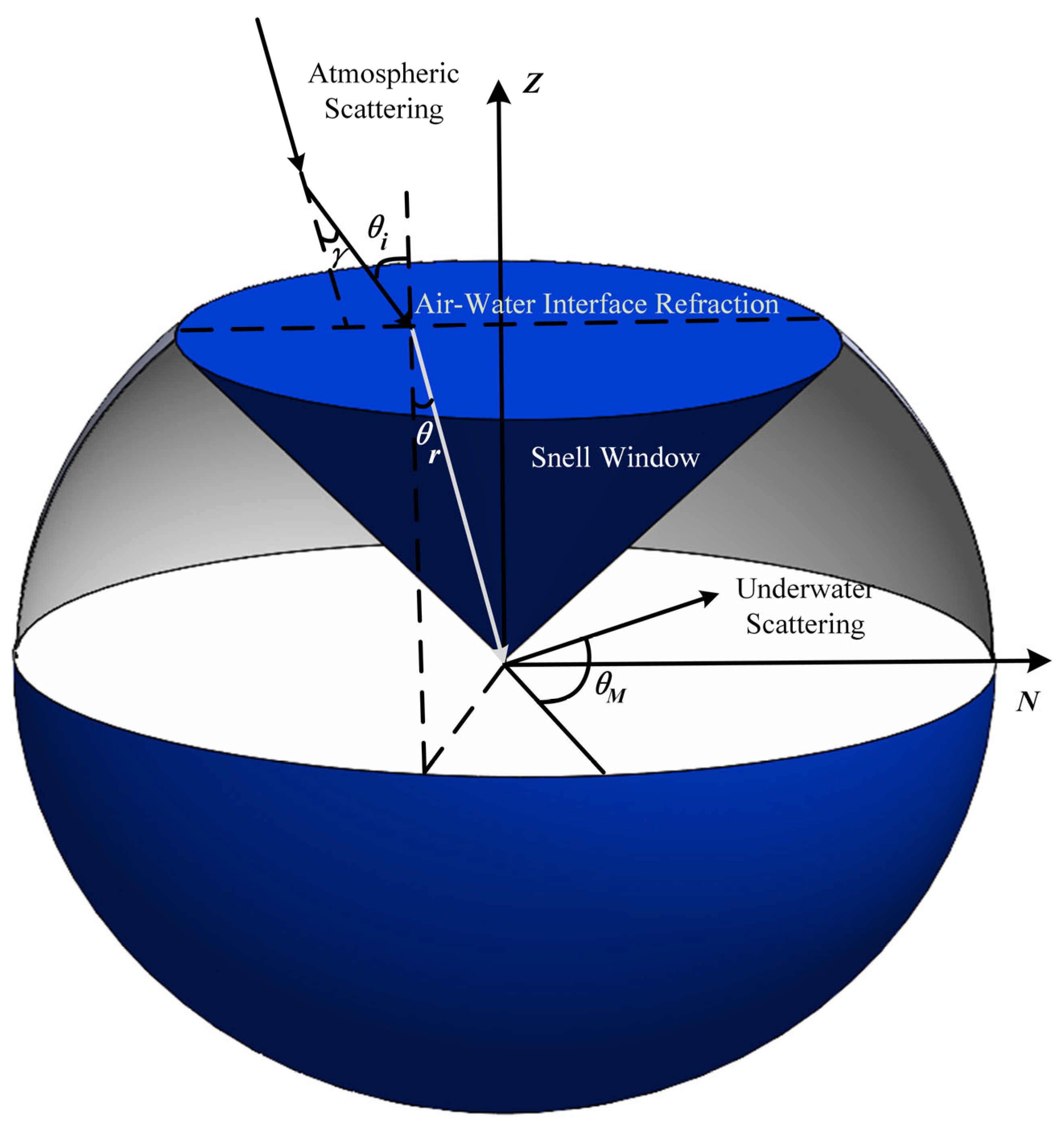
  56. Hu, P.; Yang, J.; Guo, L.; Yu, X.; Li, W. Solar-tracking methodology based on refraction-polarization in Snell’s window for underwater navigation. Chin. J. Aeronaut. 2022, 35, 380–389. [Google Scholar] [CrossRef]
  57. Cheng, H.; Chen, Q.; Zeng, X.; Yuan, H.; Zhang, L. The polarized light field enables underwater unmanned vehicle bionic autonomous navigation and automatic control. J. Mar. Sci. Eng. 2023, 11, 1603. [Google Scholar] [CrossRef]
  58. Li, G.; Zhang, Y.; Fan, S.; Yu, F.; Wang, Y. Dynamic-wave interference suppression based on angular increment assistance for underwater Imaging Polarization Sensor. IEEE Trans. Instrum. Meas. 2024, 74, 5001713. [Google Scholar] [CrossRef]
  59. Xu, Z.; Wang, Z. Recent advances and future trends in foreign underwater navigation techniques. Ship Sci. Technol. 2013, 35, 154–157. [Google Scholar]
Figure 1. Temporal evolution of research output in polarized light navigation (2004–2024).
Robotics 14 00104 g001
Figure 3. Point source polarimetric heading measurement devices. (a) Distribution of polarizers (b) Signal Processing.
Robotics 14 00104 g003
Figure 5. Polarized positioning and navigation solutions in [22] by Yang et al.
Robotics 14 00104 g005
Figure 6. Symmetry and antisymmetry of AOP and AOE.
Robotics 14 00104 g006
Figure 7. E-vector orthogonality to solar vector.
Robotics 14 00104 g007
Figure 8. Underwater polarized navigation technology research hotspot map.
Robotics 14 00104 g008
Figure 9. Definition of the coordinate system and the orientations of the sun and the observation point.
Robotics 14 00104 g009
Figure 10. Interface-crossing refraction and underwater scattering.
Robotics 14 00104 g010
Table 1. Summary of existing bionic polarization navigation techniques.
MethodsTheoretical BasisAdvantagesLimitations
Point source polarization navigationThe zenith polarization angle maintains a perpendicular relationship (±90°) with the solar meridian [17]Bioinspired sensor design, Minimal hardware complexity180° directional ambiguity; Occlusion vulnerability; Tilt-induced zenith measurement failure
Orthogonal polarizers (0°/90°) for solar meridian detection [19,20,21]Omnidirectional capabilityGear-limited angular resolution; Local measurement constraints
Multi-point observation [22,23]Direct geolocation from initial coordinatesSignificant geodetic error; Environmental occlusion sensitivity
Global Polarization NavigationSymmetry axis extraction [27,28] Simple implementation; Direct pattern analysisNoise sensitivity; Limited environmental adaptability
E-vector orthogonality to solar vector [13,29,30]Robust to partial occlusions (clouds/foliage)Motion artifact susceptibility; Device precision limitations
Model-measurement error minimization [24,26]Effective in obstructed environments; a hybrid physical-data approachPositioning accuracy limitations; DL model interpretability challenges
Table 2. Summary of underwater polarization navigation techniques.
SourceEnvironmental ConditionsEvaluation MetricsRemark
Wang et al. [55]/No specific quantitative errors, mainly theoretical analysis/
Hu et al. [56]Depth: Shallow water (pool experiment, size 5 × 3 × 1.5 m3);
Weather: Clear weather;
Surface: Calm water.
Solar zenith angle RMSE: 0.3°;
Solar azimuth angle RMSE: 1.3°.
Proposed a solar-tracking algorithm (RPA) based on refraction–polarization patterns in Snell’s window
Cheng et al. [57]Depth: 1 m, 3 m, 5 m;
Water quality: Pool (clean), actual underwater environment (poor water quality, with breeze causing waves);
Scene: Static pool experiment, outdoor actual underwater dynamic navigation.
Pool experiment: Average error of course angle measurement 0.30°, polarization azimuth accuracy < 0.69°;
At 5 m depth: Angle error MSE = 16.57°, SD = 4.07°;
Positioning accuracy: 100 m navigation error < 5 m (within 5 m depth).
Developed a strapdown navigation method combining polarization and inertial information
Li et al. [58]Depth: 30 cm (simulated underwater scene with acrylic container);
Disturbance: Dynamic waves (amplitude 10 cm);
Weather: Clear weather.
Static orientation error reduced by 26.3%;
Dynamic orientation error reduced by 33.4%;
AOP image: MSE, PSNR, SSIM improved.
Proposed a dynamic wave interference suppression method based on angular increment assistance
Powell et al. [24]Depth: 2–20 m;
Locations: Multiple global sites (Australia, USA, Finland, etc.);
Time: From sunrise to sunset;
Water quality: Clear to turbid waters.
Solar azimuth RMSE: 6.02° (after kNN correction);
Solar elevation RMSE: 2.92° (after kNN correction);
Positioning accuracy: Average 61 km, error 6 m per kilometer.
Realized underwater geolocalization based on bionic polarization vision, used kNN regression to correct residuals of single-scattering model
Bai et al. [25,26]Locations: 4 global sites (USA, North Macedonia);
Water quality: Freshwater lakes (visibility ~0.3 m, >10 m), seawater (0.5–3 m visibility);
Season: Covering different seasons.
Daytime: The longitudinal accuracy can reach about 55 km (up to a depth of about 8 m, unaffected by water turbidity);
At night: longitudinal accuracy of about 1000 km (depth up to about 8 m);
Clear water domain (50 m depth): Transfer learning vertical accuracy of approximately 255 km.
Proposed a Transformer-based Sectoral Transformer model, combined with UKF to achieve learning-free temporal modeling
Disclaimer/Publisher’s Note: The statements, opinions and data contained in all publications are solely those of the individual author(s) and contributor(s) and not of MDPI and/or the editor(s). MDPI and/or the editor(s) disclaim responsibility for any injury to people or property resulting from any ideas, methods, instructions or products referred to in the content.

