1. Introduction
Robotic technology has the potential to transform the assessment of confined-space infrastructure, particularly in the United Kingdom, where the sewer network, which is an example of confined infrastructure, dates back to the Victorian era, spans 393,460 km, and plays a vital role in urban infrastructure [
1]. Despite its significance, the water industry faces a number of substantial challenges [
2]. Much of the available autonomous robotic technology is still in the development stages, with current commercial inspection robots relying heavily on traditional methods involving tethered crawlers equipped with integrated video camera systems [
3]. Although these robots are effective, they face notable limitations [
4]. Their maneuverability is restricted by heavy, unwieldy tethers, hindering their ability to navigate tight spaces and corners [
5]. Consequently, they are mainly suitable for inspecting straight pipe sections, resulting in a slow and cumbersome inspection process [
6].
In addition, current robotic systems require manual control by operators, making the process time-consuming and labor-intensive [
7]. This dependence on human intervention slows inspections and limits the potential for fully autonomous operations. Furthermore, these robots are typically designed for basic inspections and lack the capability to perform complex tasks such as data sharing for combined decision-making. Addressing these limitations often requires additional equipment, further increasing operational costs. Although research and development in pipeline robotics is progressing, significant gaps remain in achieving efficient, autonomous, and cost-effective inspection solutions.
In recent years, several types of pipe inspection robots have been developed to tackle the challenges of inspecting pipelines [
8]. Pipeline Inspection Gauge (PIG) robots are the industry standard for inspecting oil and gas pipelines. However, they face significant limitations when used in sewer systems, especially in navigating tight bends or sections with a short radius, which are common in sewer pipes [
9,
10]. Screw-type robots, which move by rotating like a screw, are another type used for pipe inspection. While they work well in some environments, they can struggle in pipes containing sludge or debris because the screw threads can become clogged or obstructed, leading to reduced efficiency or mechanical failure [
11]. Inchworm-type robots, inspired by the movement of an inchworm, use expandable and contractible segments to propel themselves forward [
12]. While effective in certain situations, they are slower and require more energy because of their step-by-step gripping and stretching motion compared to other robots. Snake-like robots are designed to mimic the flexible and slithering movement of a snake, making them highly adaptable to navigating complex spaces within pipes [
13]. However, these robots can struggle in environments containing sludge or debris, as their motion relies on multiple mechanical joints and linkages. If any of these linkages become obstructed by debris, the coordinated gaits required for locomotion may fail to execute properly, significantly hindering the robot’s ability to move effectively through the pipe. On the other hand, wheeled robots are often preferred in pipe inspections because they move faster and more smoothly through horizontal, vertical, curved, and branched pipelines. Their simpler design also makes them more cost-effective to manufacture and maintain compared to more complex robots, such as inchworm or screw-type robots [
14,
15].
The emergence of autonomous pipe inspection robots offers a promising opportunity to address these challenges. Untethered mobile units equipped with various sensors have the potential to operate autonomously within buried pipes [
7,
16,
17,
18,
19]. However, previous systems have faced constraints on size, autonomy, and collaborative capabilities. The Joey robotic platform [
20] represents a notable advancement in this domain. Designed for inspecting smaller sewer pipes, Joey robots feature a compact mechanical design, integrated batteries, and self-contained electronics. Their adaptability is further demonstrated by their ability to incorporate additional components for visual inspection and localization. Additionally, their power-efficient design ensures sufficient battery life to meet the performance demands of small-scale robotic systems. The Joey and the later Mega-Joey robots were designed to test locomotion methods, e.g., whegs, wheels, or tracks, and to test autonomous inspection algorithms in a test sewer pipe network.
The use of collaborative robotic assessments in confined pipeline networks has yet to be investigated, despite the fact that it has proven to be highly effective in open environments. In sewer maintenance, the integration of collaborative robots capable of maneuvering through diverse terrains and performing coordinated tasks is becoming increasingly essential [
21]. These robots offer a transformative approach to pipe inspection [
22] and maintenance [
23], particularly in complex underground networks where accessibility and navigation are significant challenges. Their ability to traverse various terrains, from narrow conduits to larger sewer lines, allows them to access areas that are otherwise unreachable for human workers or conventional machinery. This capability ensures a comprehensive assessment of the sewer system without causing blockages. Collaborative robots excel in performing synchronized tasks, leveraging collective intelligence to efficiently tackle complex challenges. By working together, these robots can navigate and inspect extensive stretches of sewer pipes far more quickly than individual robots or human workers. This approach accelerates the inspection process while minimizing disruptions to regular sewer operations. Additionally, their collective sensing and imaging capturing capabilities enable the collection of detailed and accurate data, facilitating the early detection of potential issues.
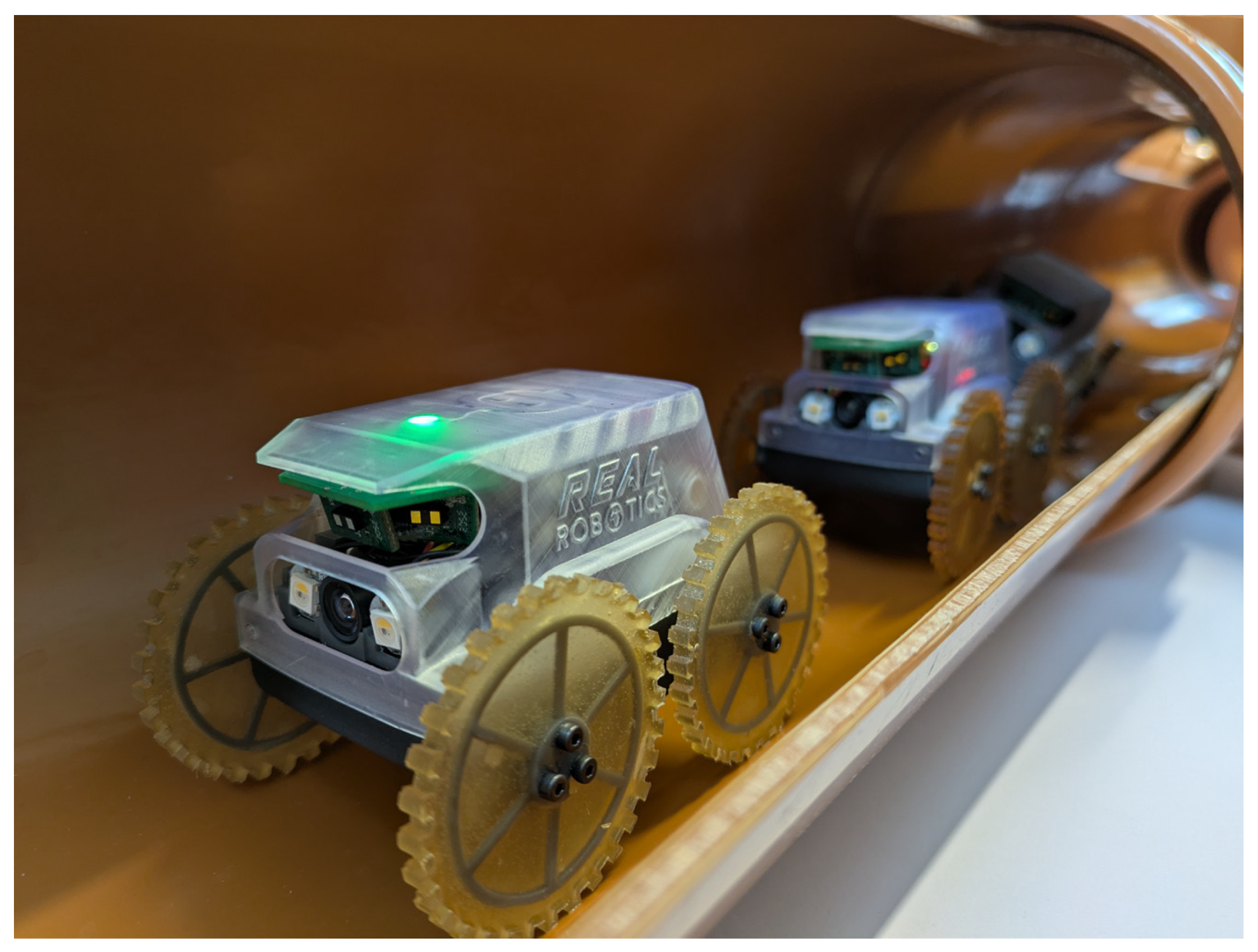
In this research work, Mega-Joey (
Figure 1), the successor to the Joey robotic platform [
20], is introduced. Designed as a compact and cost-effective system, it demonstrates how collaborative robotics can advance pipeline inspection practices. The platform integrates autonomous navigation through sensing and coordinated operations, offering greater efficiency and potentially lowering the costs of pipeline inspection tasks. Through collaborative teamwork, Mega-Joey robots achieve better performance in both the time needed to complete an exploration task and energy efficiency compared to a single robot. Using multiple robots also increases the redundancy of the overall task.
Additionally, a novel exploration algorithm based on broadcast messages is introduced. This broadcast-based decision-making strategy offers several advantages. It allows the robots to make autonomous decisions with minimal communication overhead while consuming minimal energy. All robots broadcast, receive, and process messages for coordinated exploration. In broadcast-based communication, all robots have global awareness and know the status of each robot, enabling them to make efficient and adaptive decisions for the next course of action. On the other hand, point-to-point communication, where each robot communicates individually with another robot, is less efficient, as it can take a long time for all robots to receive the status of a single robot. As a result, some robots may remain unaware of the status of others, leading to delays and making the robots inefficient.
The contributions of this research can be summarized as follows:
Compared to the previously developed Joey robot, Mega-Joey features an improved mechanical design, including upgraded motors, encoder placement, and treaded wheels along the circumference, resulting in more stable and faster locomotion inside confined pipelines.
A lower center of gravity was incorporated into the design to reduce the likelihood of flipping during motion and turning, which improves reliability.
A novel decentralized, broadcast-based exploration algorithm is introduced, allowing a team of Mega-Joeys to collaboratively explore pipeline networks.
The structure of this article is as follows:
Section 2 delves into the mechanical system design and autonomous exploration architecture of the robot. This is followed by
Section 3, where the experimental results are presented. Finally,
Section 4 and
Section 5 provide in-depth discussions and concluding remarks, respectively.
2. Materials and Methods
The mechanical design evolution from Joey to Mega-Joey involved several significant advancements aimed at refining the robot’s functionality. Through multiple iterative design changes, various flaws and challenges were addressed, focusing on improving stability, enhancing electronics integration, and accommodating additional sensors.
While retaining the core electronics and software from its predecessor, it introduced critical improvements. These included a larger battery for extended operation, a stronger chassis, and larger motors with encoders placed directly on the motor shaft for precise control. The electronics package and range sensor mounting were re-engineered for better reliability and ease of assembly. Additionally, the wheel mounts were redesigned to support diverse locomotion options, enabling compatibility with larger wheels. A comparison of the size and drive mechanism of Joey and Mega-Joey is depicted in
Figure 2.
Joey was usable in 110 mm and larger pipes, but Mega-Joey can only be used in 160 mm and larger pipes. This trade-off was acceptable given the ability to easily change the wheels, faster assembly times, and the much greater running time: up to 60 min of continuous movement and up to 6 h in standby mode. The increased ground clearance, 16.5 mm instead of 8 mm, allows Mega-Joey to climb over larger obstacles such as pipe joints and debris. A size comparison of Mega-Joey and its predecessor is shown in
Table 1.
2.1. Mega-Joey Assembly
An exploded view of Mega-Joey is shown in
Figure 3. Mega-Joey is made up of four main parts: the chassis, the motor assembly, the electronics assembly, and the upper shell.
The upper shell provides protection for the internals of Mega-Joey. It is fitted to the chassis using 4 bolts. The chassis is fitted with two 5-element gear trains, with one on each side, to distribute the power from the motor to the front and back wheels. Each wheel is made up of a 3D-printed structure (visible in
Figure 2), which is used to mount the wheels on a matching 3D-printed part at the end of each wheel shaft. The main bulk of the wheel is cast in polyurethane elastomers. This allows us to create different wheel shapes and sizes with a range of different materials for future experiments.
The motor assembly is made up of a motor bracket fitted with two Micro-Metal gear motors with a gear ratio of 298:1. Each motor is fitted with a magnetic encoder that is used to control the speed of the motor and provide odometry data. The output shaft of each motor is fitted with a bevel gear that allows the output power to be rotated through 90° to align with the shaft of the gear train. The motor assembly is bolted to the chassis and has mounting points for the electronics assembly. Heavier components are purposely placed lower in the assembly to keep the center of gravity low for the robot.
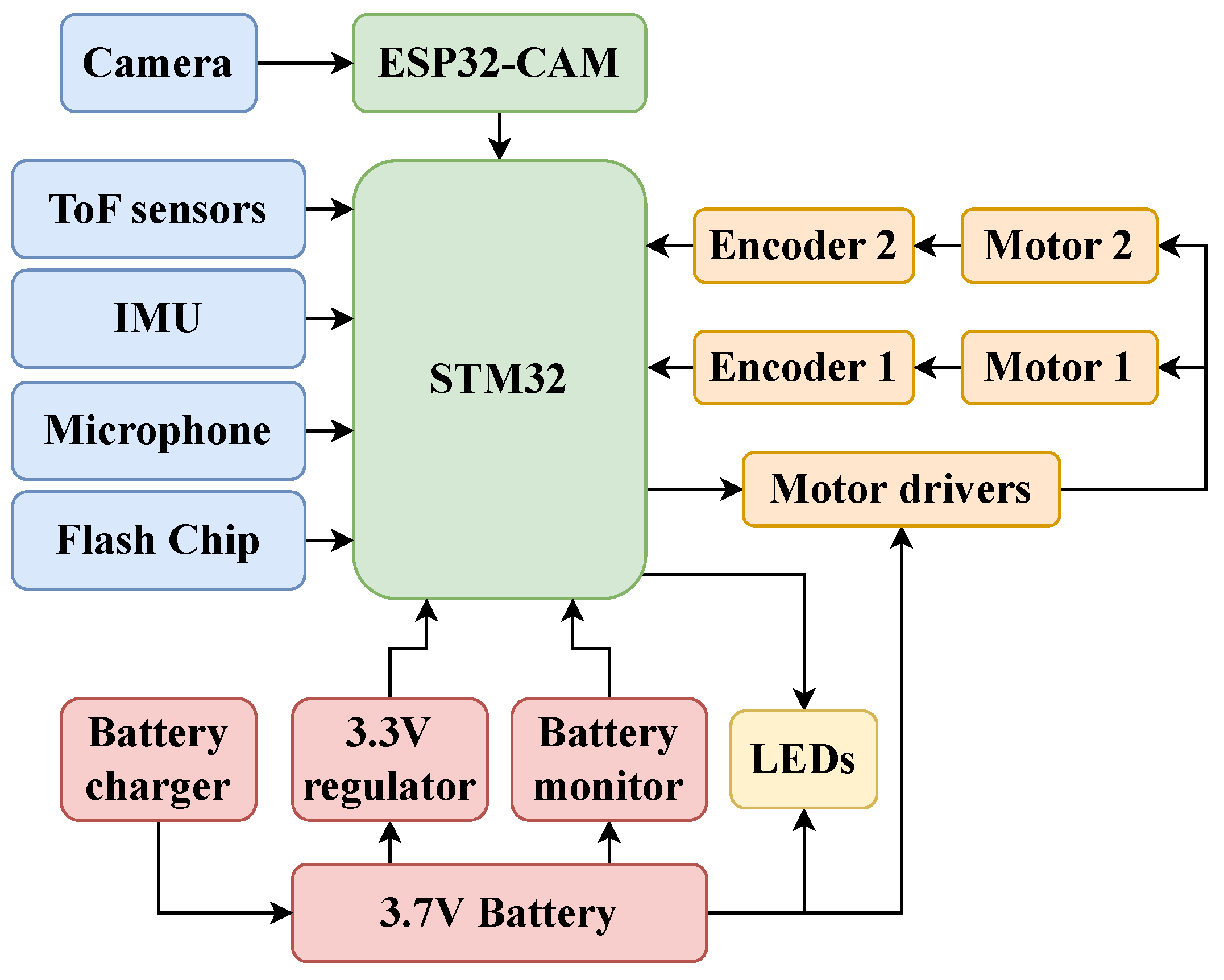
Figure 4 depicts the connections of various electronic components onboard the robot. The electronics assembly is designed to support various electronic components. The ESP32-CAM board plugs directly into the companion board to form a very compact module that is carefully slid into the electronics bracket. The OV2640 camera and two of the three Neo-Pixel LEDs are secured onto the electronics bracket. The ICM-20948 9-axis inertial measurement unit (IMU) is bolted to the top of the electronics bracket, as is the time-of-flight sensor board. The battery is a 1S 750 mAh LiPo cell. It was selected because it had the largest capacity that was commercially available, and it could fit between the electronics assembly and the motor assembly. It is slotted in between the electronics and motor assembly.
2.2. Companion Board
The companion board is a custom-designed printed circuit board (PCB) that provides a method for controlling most of the hardware of the Mega-Joey robot. The program running on the ESP32-CAM board sends commands to the companion board, and the companion board responds with data gathered by the attached peripherals. The two boards communicate using custom JSON messages over a serial connection that was used to allow easy debugging. The companion board is shown in
Figure 5A and is fitted with the following:
A STM32WB5MMG microcontroller: This runs the driver software, which controls the two motors, communicates with the EPS32-CAM board, saves the sounds captured by the microphone onto the flash chip, controls the Neo-Pixels, and captures power usage information. It also offers Bluetooth and Open-Thread wireless communications, but these features are not used.
A ST IMP35DT05TR MEMS microphone, which has low power consumption, high sound pressure detection, and a strong signal-to-noise ratio, making it ideal for sewer inspections in noisy environments.
A Cypress S25FL128P flash chip for storing audio data from the microphone.
A battery charging and monitoring circuit.
A DRV8833 dual H-bridge motor driver.
A USB micro-B charging and programming port.
Voltage regulators.
Other necessary connectors.
Figure 5.
(A) Custom designed electronics STM32-based companion board. (B) Custom-designed array of time-of-flight sensors. (C) ESP32-CAM board. (D) OV2640 camera.
Figure 5.
(A) Custom designed electronics STM32-based companion board. (B) Custom-designed array of time-of-flight sensors. (C) ESP32-CAM board. (D) OV2640 camera.
2.3. Time-of-Flight Sensor Board
The time-of-flight (ToF) sensor board is shown in
Figure 5B. It consists of three STMicroelectronics VL53L1X ToF sensors mounted on a custom PCB. The PCB is designed to position the sensors at different angles: The middle sensor points forward, while the other two are angled at +30° to the left and −30° to the right. The forward-facing ToF sensor detects blockages, while the angled sensors are used to detect branches in the pipe network.
The board also includes an XC6210 voltage regulator, which provides the 3.3 V required for the ToF sensors and a PCA9536 Remote 4-Bit I2C and SMBus I/O Expander, which is used to select each ToF sensor during initialization. The board is connected to the companion board via a STEMMA QT/Qwiic compliant connector.
2.4. ESP32-Based Communication
The ESP32-CAM micro-controller, shown in
Figure 5C, is a commercial off-the-shelf board, which was selected for its compact form factor and capability to interface with a camera and store image data on a micro-SD card. This micro-controller performs the key functions of controlling the robot’s actions by exchanging data with the companion board, storing video and static images on the SD card, and enabling Wi-Fi communication using the ESP-NOW protocol. This facilitates efficient data exchange between robots and the base station for sensor transmission, which is critical for the operation of collaborative robotic systems (
Figure 6). To enable open-loop testing, a joystick or gamepad can be connected to the base station and used to send commands to individual robots.
ESP-NOW is a low-power communication protocol supported by ESP32 micro-controllers. It enables multi-point communication without the need for an external router or separate transmitter/receiver units, as it operates directly on the ESP32 board. Another benefit of this protocol is its support for message multi-hopping, which can be used to create a communication network among robots operating inside a pipeline. This allows us to relay messages and share sensor data over long distances through intermediate nodes.
The camera interface allows a range of different cameras to be used. We selected the OV2640 camera (
Figure 5D) with a 160° wide-angle lens to maximize the view of the pipe and a longer ribbon cable to allow us to position the camera at the front of the Mega-Joey. The camera has a wide range of resolutions, with a maximum of 1600 × 1200 pixels. This flexibility allows us to capture high-resolution images of defects for later analysis, while lower resolutions can be used for the real-time recognition of pipe features for navigation. The onboard LEDs improve visibility in low-light conditions, enhancing the camera’s performance.
3. Collaborative Exploration of Pipeline
This section outlines the autonomous exploration architecture of the robots in the pipeline.
3.1. Autonomous Control of States
Similarly to the previously developed Joey, different robot states are defined to account for the various scenarios the robot may encounter within a pipe network. Each state is determined using data from the robot’s three distance sensors, enabling the robot to autonomously detect its current state and evaluate its exploration status. It should be pointed out here that although Mega-Joey robots are equipped with a camera onboard, in this research, it is not utilized. The following states are included in the autonomous control strategy.
The
in-pipe state is identified when the sensors detect walls on both the left and right sides. Wall detection is achieved by applying a threshold to the sensor readings. This threshold was determined through experimental data collected from multiple in-pipe runs of the robot, which established the minimum and maximum distance ranges for the in-pipe state. The robot identifies a
left corner or
right corner when it detects an opening to the respective side, and the central sensor reading is lower than the distance to the walls. Similarly, a
T-junction is detected if the robot senses openings on both the left and right while the central reading remains lower than the wall distance. For the
left branch or
right branch, the robot detects an opening to the respective side, but the central reading exceeds the wall distance. A
dead-end is recognized when walls are detected by all three sensors, whereas an
open area is indicated when all three sensors register maximum values, signifying no nearby obstacles. These states, along with descriptive diagrams, are explained in detail in the previous Joey publication [
20].
In addition to these, the robot detects critical states using data from its IMU. The
flip-risk state occurs when the robot identifies a risk of flipping forward, backward, or sideways due to an over-inclined orientation. The
crash state is triggered when the robot is flipped onto any of its sides, with the direction of the flip determined through gyroscopic data. Additionally, the robot uses magnetometer data to monitor its global heading angle (
), where
and
are the raw magnetometer values obtained from the IMU. The robot moves in the correct direction and performs precise closed-loop turns at corners, T-junctions, and branches using its three ToF sensors. The ToF sensors are used to calculate the distance from the walls of the pipe. This distance data is used to calculate a lateral error (
):
where
and
are the left and right distances, respectively. The steering adjustments (
) for the robot are calculated using a standard proportional-integral-derivative controller:
where
,
, and
are the proportional, integral, and derivative gains. This steering adjustment is then mapped to each motor to obtain the desired directional correction. The above-mentioned states are detected in parallel with an autonomous exploration algorithm, which guides the robot to a correct branch for exploration.
3.2. Autonomous Exploration Algorithm
The autonomous exploration architecture followed by the robots is depicted in
Figure 7. This framework illustrates the process through which the robot’s motion planner receives data from various sensors as broadcast messages from other robots, determining the next maneuver and broadcast message for each robot. An autonomous pipeline exploration algorithm, described in Algorithm 1, is designed to run independently on each robot.
| Algorithm 1 Exploration algorithm running on each robot independently |
Definitions: - R = , , …, : Set of robots
- B = , , …, : Set of branches
- D = Left, Right : Set of directions
- , : Wait times
- X: Branch counter
- E: Set of explored branches
Algorithm for each :
Initialize:
- 1:
- 2:
Main Loop: - 3:
while not at the end of main pipe do - 4:
if !CrashDetected() then - 5:
MoveForward() - 6:
if detect branch with direction then - 7:
- 8:
Broadcast() - 9:
Wait() - 10:
if !ReceiveResponse() then - 11:
Broadcast() - 12:
EnterAndExplore() - 13:
- 14:
Wait() - 15:
Broadcast() - 16:
else - 17:
MoveForward() - 18:
end if - 19:
end if - 20:
else if EdgeConditionDetected() then - 21:
Stop moving - 22:
end if - 23:
end while - 24:
Concurrent Process for each : - 25:
on receiving message m do: - 26:
if and ( or ) then - 27:
Broadcast() {Confirm branch is occupied/explored} - 28:
else if then - 29:
Ignore message {No action required} - 30:
else if then - 31:
{Update branch as explored} - 32:
else if then - 33:
Ignore message {Message reconfirms branch status, no action needed} - 34:
end if - 35:
end on Termination: - 36:
if and then - 37:
return “Exploration Complete” - 38:
end if
|
The algorithm’s design is based on broadcast messages, so all robots receive the same information simultaneously, creating a common knowledge base. Moreover, broadcast-based communication can save the energy of the robots in the pipeline environment and prolong the mission. Additionally, the algorithm is decentralized, so the information about the robots’ and branches’ states is stored locally on each robot rather than being managed by a centralized base station.
Considering the number of robots in the mission as
n, the number of messages exchanged using a point-to-point communication strategy is
messages. On the other hand, the number of messages in broadcast strategy is
messages. Taking a ratio of these two gives
which shows that the broadcast strategy requires only a fraction of the messages needed for point-to-point communication. Assuming
and
as the energy required for point-to-point and broadcast strategies, respectively, the energy equations can be written as
where
is the energy for transmission, and
is the energy for the reception of each message;
is the peer management energy.
The efficiency ratio is given as
For large
n,
Typically for ESP-NOW communication,
. Therefore,
, which proves that for larger values of
n, the energy required by the point-to-point strategy exceeds that of the broadcast protocol.
The inputs to the algorithm include the robot’s current state, current time, broadcast messages received from other robots, and previously processed data. The proposed exploration algorithm produces two key outputs: navigation commands and broadcast messages, for communication with other robots. The navigation commands direct the robot to either ‘Move forward’ or ‘Enter and investigate a branch’. A function ‘MoveForward()’ commands the robot to advance while maintaining a specified velocity and heading. A closed-loop controller ensures that these parameters remain consistent throughout movement. Function ‘EnterAndExplore(b,d)’ directs the robot to enter branch b in direction d and explore it to the end. The robot uses its state information to determine the branch’s opening direction d, and it uses its heading data to make a precise 90° turn in the required direction. The algorithm uses a function ‘ReceiveResponse()’, which returns true if a response broadcast message is received from another robot and false otherwise.
If the robot detects a T-junction, it identifies two branches in opposite directions in line 6 of Algorithm 1. In such cases, priority can be assigned to either the left or right branch for the first encounter, as desired. Subsequent robots will then proceed according to the instructions provided by the algorithm.
The robots exchange four distinct types of broadcast messages (M), as defined by the following algorithm:
- -
: “Any robot in branch ?”
- -
: “Entering branch ”.
- -
: “Exploring branch ”.
- -
: “Branch occupied/explored”.
Here, X represents the branch counter, and d represents the direction of the turn. serves as a branch query, which each robot must confirm before entering. serves as a robot’s confirmation for entering. Each robot confirms its branch assignment by sending . Finally, serves as a reconfirmation message for each branch, which can be ignored, unless the robot missed the earlier branch assignment message. The algorithm uses function EdgeConditionDetected() for relaying an ID to the other robots and ground station if an edge condition is detected, such as dead ends, obstruction, communication disruption, etc.
Adjusting the parameter values allows control over the number of robots assigned to explore a specific branch, enabling effective coordination for further exploration within that branch.
4. Experimental Results and Discussion
The Mega-Joey robots developed in this research work were thoroughly tested via a series of in-pipe experiments to examine its capabilities. These include effective locomotion inside pipelines, the detection of features using a sensor array, and effective exploration statuses relative to other robots. This section discusses the results obtained in detail.
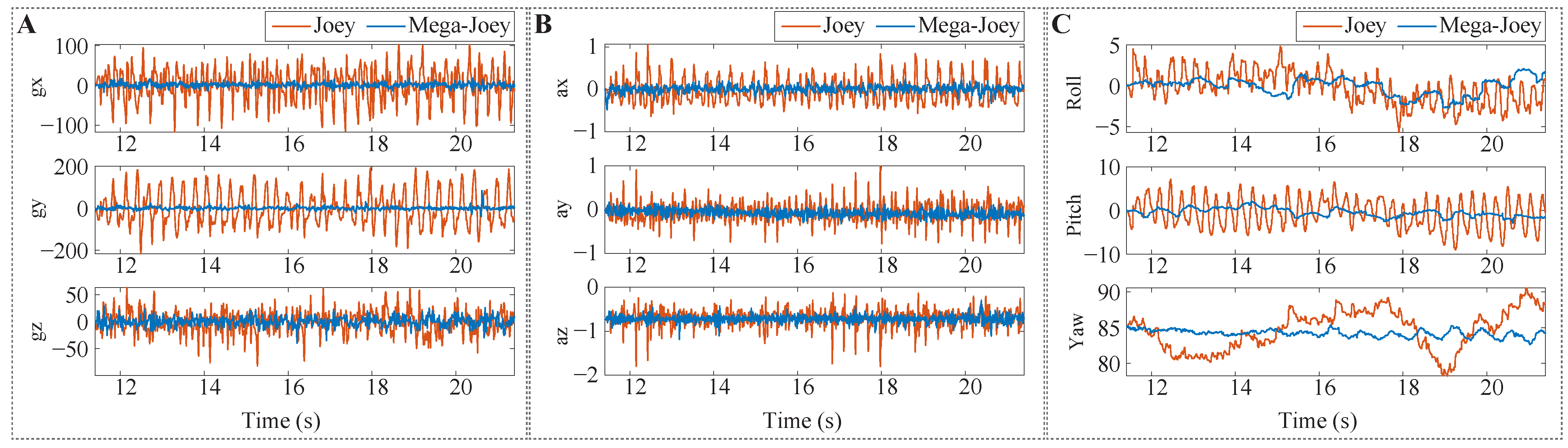
Figure 8 compares the accelerometer and gyroscope data, as well as the body-frame Euler angles, of Joey and Mega-Joey. The results indicate that the design improvements in Mega-Joey contributed to more stable motion. Experiments were carried out to thoroughly test the robots under different pipe conditions. All pipes used in the experiments are made up of UPVC material, having a diameter of 160 mm. The previous iteration of the robot struggled to move efficiently due to its higher center of gravity and often flipped and crashed while turning or moving across pipe joints. Mega-Joey was tested to find its limiting conditions in similar scenarios. The lower center of gravity helped Mega-Joey to move in the pipe while being tilted on its side at 30°. The larger footprint of the robot helped it to turn around corners more efficiently without flipping on its sides. The robots’ ability to navigate inside inclined pipes was evaluated in both dry and wet conditions. Mega-Joeys were able to climb pipes with inclinations of up to 20° in dry conditions; however, this capability decreased to 10° in wet pipes as the robots lose traction during movement. This is still steeper than the recommended slope according to the UK National House Building Council [
24].
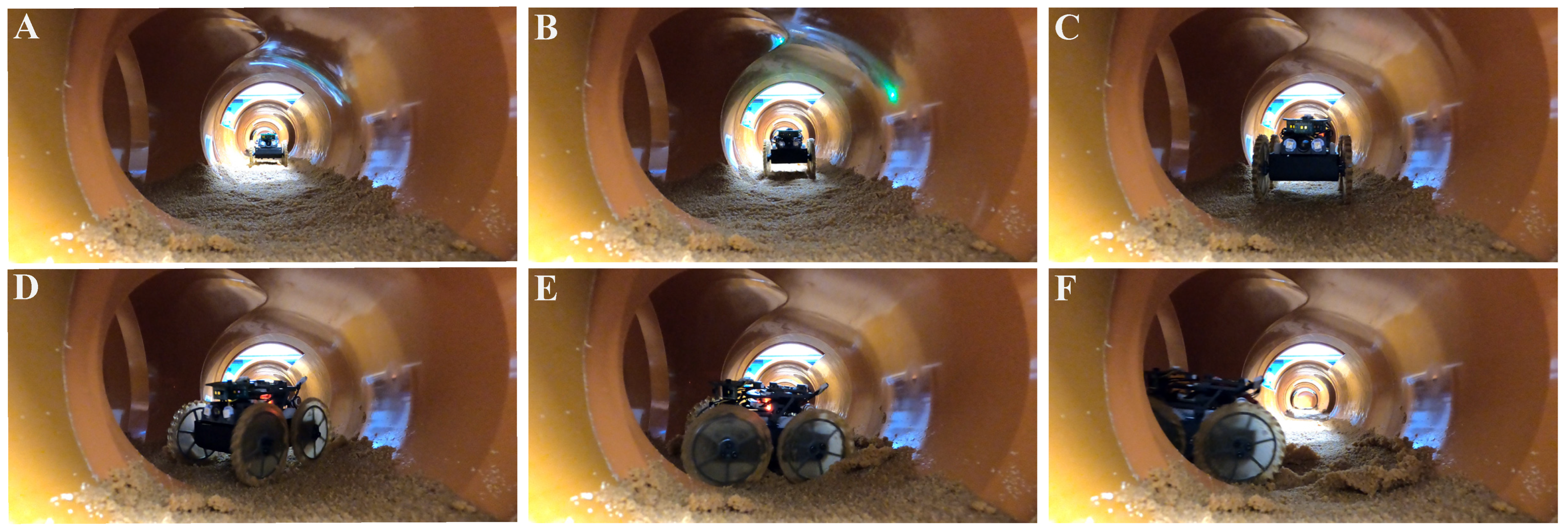
In real-world scenarios, pipelines can often accumulate sediments such as mud/sand at the bottom, which can present additional challenges for robots exploring these pipeline networks. To simulate such realistic conditions, a pipeline network with heavy sediment deposits using saturated olivestone [
25] was created to access the robot’s ability to traverse such environments.
Figure 9 shows the frames from
Supplementary Video S1, depicting a robot making a turn at a junction during an experiment and demonstrating its capability to maneuver in muddy and slippery conditions.
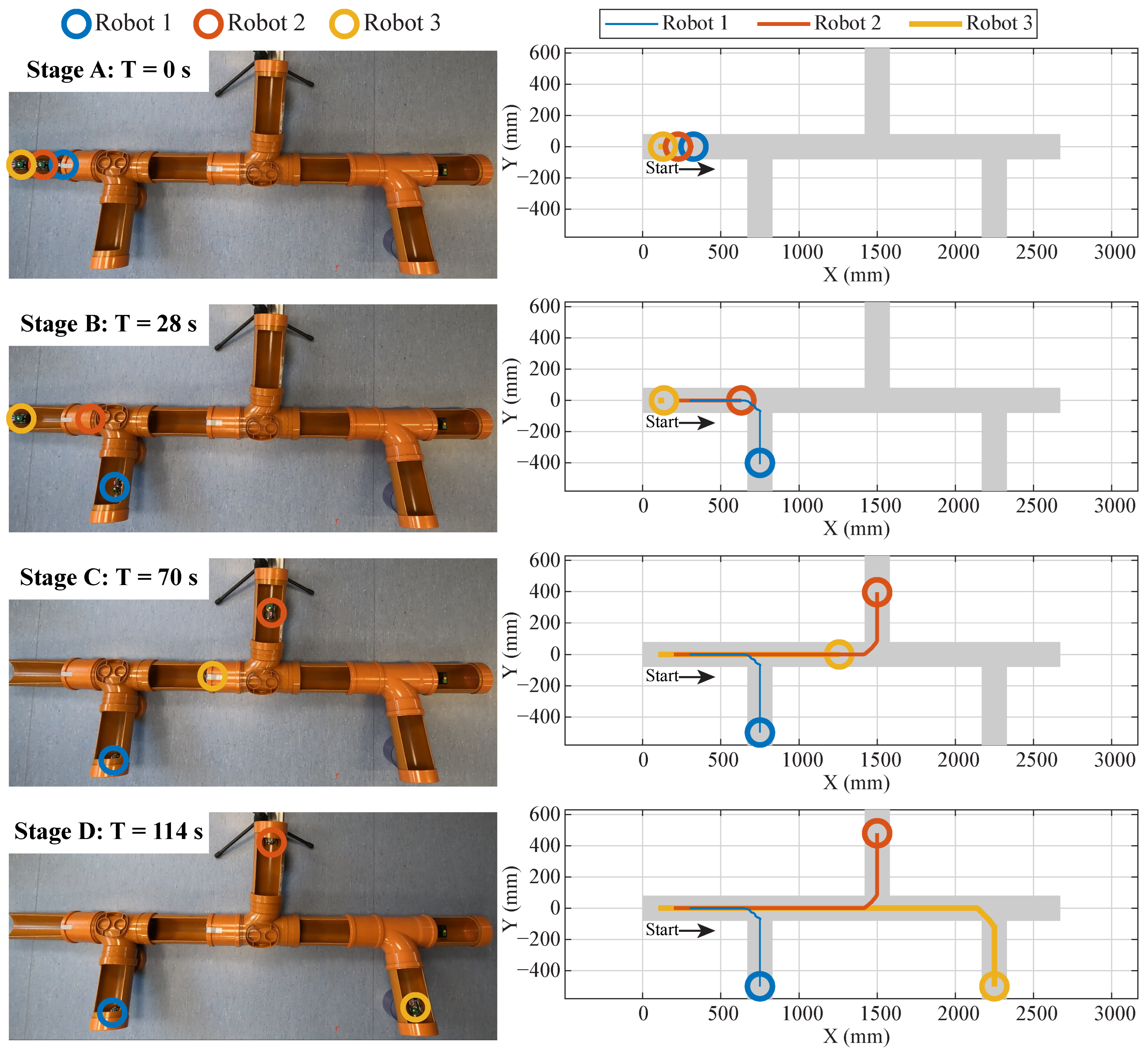
For this research, experiments were conducted using team of three Mega-Joey robots within a custom-designed experimental pipe network. The network features a main pipeline and multiple branches extending from either side, as shown in
Figure 10. The main pipeline has a total length of 2.67 m, with junctions positioned at 0.75 m, 1.5 m, and 2.25 m. To simplify the experimental setup and ensure visibility within a single video frame, the branches were limited to a length of 0.5 m, terminating in dead ends. With the main pipeline lying flat on the ground, the branch sections were placed at angles ranging from 10° to 15°.
If the exploration of such a network is carried out using a single robot, the robot will firstly drive to the end of each junction and then either turn around or reverse to the main pipeline after reaching the end of the branch. This can take plenty of time if the branch sections are long, which will have to be covered twice by the robot. Additionally, turning around in a pipe of small diameter can consume a lot of energy for a robot of this size. Similarly, reversing blindly with no camera or sensor help can result in getting stuck in non-recoverable states. Therefore, using multiple robots is well suited in exploration scenarios such as these.
To obtain benchmarks, a single robot was used to run the course from the starting position to the end position by reversing at the end of each branch (to save the time and energy of turning 180°). Since no sensors are mounted on the back of the robot, reverse turns were manually commanded at the end of the junction. The time taken by a single robot to explore all the branches is approximately 180 s. The robots were then tested, as a team, in the described experimental pipe network to evaluate the capability and effectiveness of the proposed exploration algorithm. The robots were assigned the task of collectively exploring all branches of the main pipeline while communicating with each other to avoid the overlapping of explored sections.
Figure 10 depicts the position plot of the three robots in the
X and
Y axes during experiments, overlaying the pipe network. Moreover, frames from
Supplementary Video S1 show the position of the robot in the pipe network at specific time instances. Collectively, the robots take approximately 114 s to explore the given network. A communication plot illustrating the algorithm messages that robots exchange during the experiment is depicted in
Figure 11.
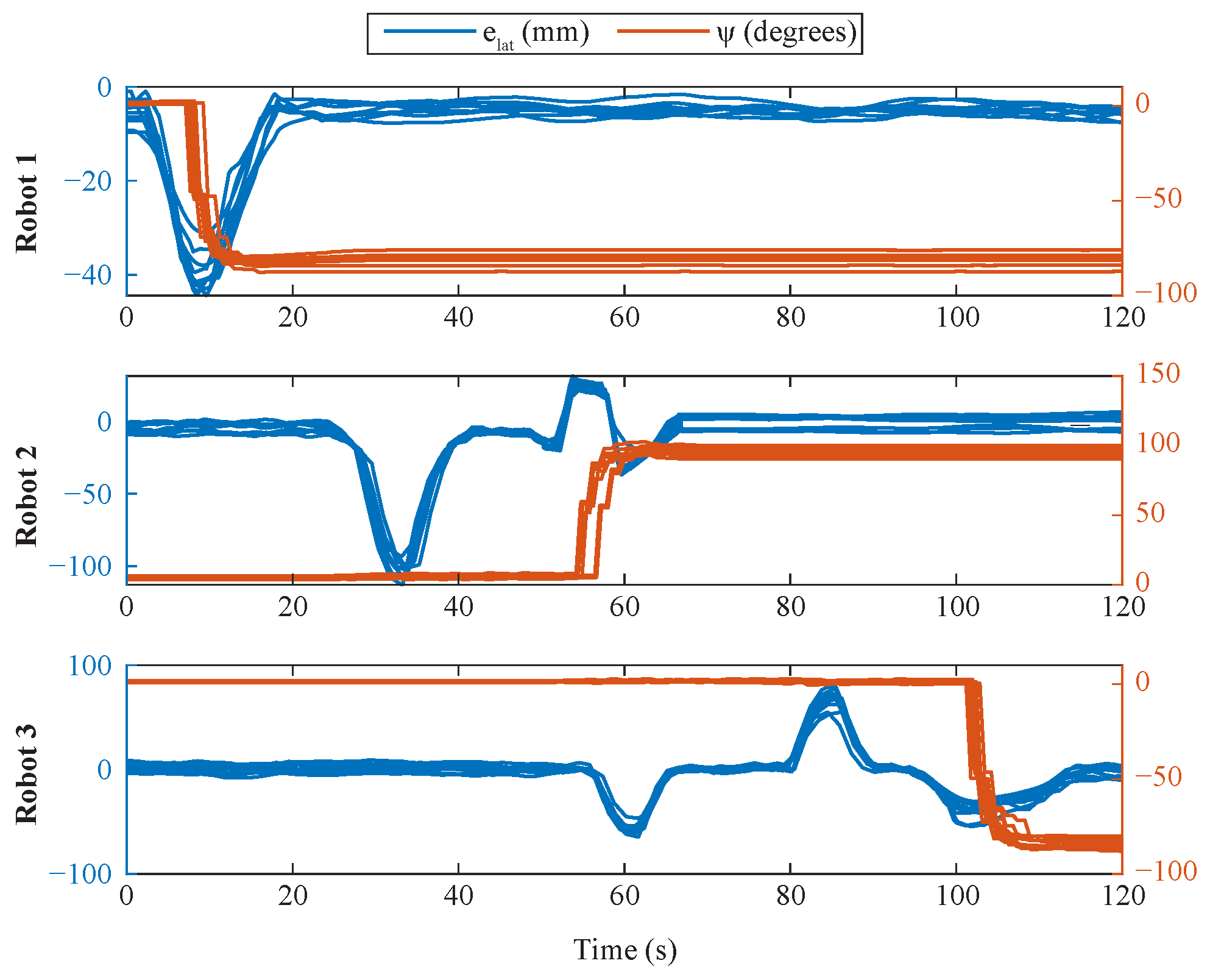
Given that the robots are operating autonomously with the exploration algorithm, the experiment can be easily scaled to accommodate additional robots, demonstrating the algorithm’s ability to handle larger teams and more complex pipeline networks. The exploration experiment was conducted for a total of 10 times to evaluate the accuracy of turn detection; decision-making at junctions based on sensor data; the robots’ ability to turn at the correct angle to explore branches; and their capacity to send the correct messages after entering and completing the exploration of each branch. A plot depicting the lateral error of the three robots during multiple runs is presented in
Figure 12. As the robots move, it can be observed that they attempt to minimize this error by maintaining their position between the two walls. Peaks are observed in the lateral error plots near junctions due to the temporary absence of walls. If a robot is not required to turn at a junction, this temporary increase in error is disregarded (e.g., Robot 2 at t ≈ 35 s, Robot 3 at t ≈ 60 and 85 s). The plot also includes the global heading angles of the robots during each run, demonstrating the consistency and repeatability of their behavior. The close alignment of the curves indicates that the robots are able to accurately detect and execute turns at junctions.
A T-junction was introduced into the pipe network by altering the starting positions of the robots. For this setup, priority was given to the left turn at the T-junction; however, as explained in the previous section, the experiment could have been conducted with any turn direction.
Figure 13 shows the position of the robots during the experiment, overlaid on the pipe network. Across a total of 10 runs, the average time taken by the robots to complete the course was approximately 120 s. In comparison, a single robot takes approximately 228 s to finish the same course. It is important to note that the origin and dimensions of the pipe network in this experiment are slightly different from those used in the previous one.
Figure 13 also depicts the video frames showing the robots during the experiment. A communication plot illustrating the algorithm messages exchanged among the robots during the experiment is depicted in
Figure 14.
When powered on, the Mega-Joey robot consumes approximately 0.8 W of power while idle and 1.4 W while in motion. In the first experiment, a single robot would consume approximately 252 J of energy. In comparison, when three robots completed the same course collectively, they consumed approximately 348 J of energy, averaging 116 J per robot.
This validates our initial hypothesis that a collaborative team of robots consumes less energy per robot compared to a single robot while inspecting the same pipeline. Additionally, deploying multiple small and cost-effective robots introduces redundancy in the task. On the other hand, relying on a single, more expensive robot poses a risk, as the entire exploration would halt in the event of a malfunction.
Figure 15 compares some of the experimental results of a single robot and a team of robots. The values in the figure are normalized between 0 and 1 for consistency.
The communication reliability of the ESP-NOW protocol during the experiments was evaluated using the Packet Delivery Ratio (PDR), which is defined as the ratio of successfully delivered messages to the total messages sent. According to the algorithm designed, each robot broadcasts a message that is received by the other robots. Throughout the experiments, a perfect PDR of 1.0 was recorded, indicating that all messages were sent and delivered successfully. In addition, the message latency was measured at approximately 50 ms, demonstrating the efficiency of the communication system under these experimental conditions.
5. Conclusions
The Joey and Mega-Joey robots were created to prove that small robots can effectively explore and inspect sewer pipes in teams and share their data for collaborative decision-making. The collaborative test exploration algorithm is detailed above, and the experimental results show that a small team of robots can efficiently explore a small representative network of pipes faster, with lower individual energy use than using a single robot. Using multiple low-cost robots in hazardous environments, such as sewers, also improves the probability of completing the inspection mission successfully should one or more robots fail. This approach paves the way for more frequent routine pipe inspections, which will allow pipeline defects to be identified and fixed more quickly in a low-cost manner.
Building upon previous work, this research introduced significant enhancements to the previously developed Joey robot. The primary focus of the design changes was to improve the drive mechanism of the robot to ensure more stable and efficient motion within a constrained pipe network. To this end, larger motors with high torque were utilized, and the whegs of Joey were replaced with wheels with tread along the circumference, which helped it move more efficiently. The center of gravity of the previously designed robot was high, which caused frequent flips and crashes. This was improved by adjusting the center of gravity to a lower position, which enhanced stability during turns and movement on inclined surfaces. Even though the robot was designed with a low center of gravity, the current design lacks an autonomous recovery mechanism in the event of a flip or crash inside the pipe. This limitation will be addressed through appropriate hardware and control strategies for self-recovery in future work. Future research will also focus on integrating additional sensing capabilities. The robot’s design will be enhanced to incorporate sensors on the rear side, enabling it to detect obstacles and move efficiently in reverse. Along with modifications to the robot, we also plan to conduct experiments on a larger scale, with an expanded pipeline network and a greater number of robots.

 ,
, 


