Abstract
Most of the developed and studied service robots for vertical locomotion, as visual inspection, are made up by a rigid body with legs, wheels, or both. Thus, the robot can only displace over regular and/or flat surfaces since it is not able to adapt to the irregularities and projections of the wall. Therefore, this paper presents the design and analysis of an adaptable robot for vertical locomotion service tasks, which has a body made up of four wheeled legs that can easily adapt to the different irregularities and projections of building facades. The robot uses an Electric Ducted Fan (EDF) as the vortex adhesion system. Each leg has a rubber cover, which allows a higher mechanical adaptability of the robot over different irregularities of the wall. Theoretical backgrounds and open issues are addressed by considering some challenging problems such as mechanical adaptability modeling as well as kinematic and static analysis. Laser sensors are mounted over the robot to measure the adaptability of the robot, between the legs and body, at each time of the experimental tests for vertical locomotion.
1. Introduction
In recent years, the demands for service robotics are increasing, and service robots need to be able to perform various tasks in different surroundings [1,2,3,4]. Such service tasks require the interaction of the robot with the environment, facing obstacles, people, or rough terrains [5]. In the particular case of vertical locomotion robots, the importance of professional application has been increased, such as inspection, maintenance, or cleaning, where the robot increases the operational efficiency and protects human health and safety [5,6,7,8]. In most of these service operations, the climbing robots need to navigate manifold and vertical human-made structures [5,6,7,8], like nuclear power plants, skyscrapers, or cultural heritage buildings. Almost all the current developed climbing robots have been designed to displace over flat surfaces, like glass or metal structures.
The locomotion issues and displacement limitations of this kind of robots are mainly due to their body configuration, shape, and adhesion principle. Thus, the robot should have a shape and configuration that allows displacing over all projections and reliefs without falling, and it must have a suitable adhesion technology to not harm the vertical surface. Specifically, for stone-made buildings, the climbing robots should adapt to all the irregularities, projections, and reliefs without causing any type of damage to the structure.
Within climbing robots there are different adhesion systems that can be used on rocky surfaces, such as pneumatic adhesion systems, mechanical adhesion, electro-adhesion, and chemical adhesion [5,6,7,8,9]. In pneumatic adhesion systems the main adhesion is by negative pressure, which in turn can be performed by passive suction cups, active suction cups, and a vortex system [10]. Passive suction cups are suitable only on very flat surfaces, such as glass; it is easy to combine them with different types of locomotion as in the Mapache robot in [9] and either the vehicle presented in [10] or the Dexter robot in [11], which is equipped with two articulated feet. This principle has the great disadvantage that it is not robust against disturbances such as dust, in addition to the fact that the robot must be kept in motion since the suction cups lose the negative pressure due to small leaks. As for the active suction cups, an electric generation system by vacuum pump is used, or mechanically by venturi vacuum nozzles. These active systems have the advantage that they can work in more rugged terrain compared to passive suction cups and that they are capable of generating high attractive forces. This adhesion system is also simple to use with almost any type of locomotion, such as the Wall-Bot hexapod robot presented in [12] or the robot with wheels in [13].
The vortex system is a patented method of adhesion known as Vram (movement of regenerative vortex air), which generates adhesive forces through a vortex inside the robot. This vortex is created by a high-speed rotor and allows adhesion without additional sealing elements. Until now, only a few systems have been developed by using this principle, such as the Clarifying Climber robot by Clarifying Technologies [14], the City Climber [15], or the one presented in [16], which are driven by wheels. This principle is still being investigated to improve the adhesion principle and to analyze its aerodynamics [17].
In terms of mechanical adhesion systems, the system of claws or spines is available through a grip or clamping mechanism. These systems can be used on surfaces that are sufficiently rough so that the claws or spines find sufficient points of contact, or that provide protruding elements in a structure that can be grasped. Its main advantage lies in the energy consumption of the adhesion mechanism, its applicability to rough surfaces or structures, and its safety. The adhesion based on grip is especially very safe since even a loss of power does not necessarily lead to a fall in the system (if the mechanical configuration admits it). On the other hand, these systems are not very fast and are of limited maneuverability. In addition, its payload is low compared to robots that use magnetic attraction or a pneumatic system [8]. This adhesion system can be found in robots such as CLIBO in [18], the robot RISE in [19], or the robot LEMUR in [20].
On the other hand, electro-adhesion, a growing discipline in the field of climbing robot research, consists of electro-adhesive pads composed of conductive electrodes that generate electrostatic force or Van der Waals forces between the surface and the robot [8]. Until now there have been only some robots that use this active adhesion system such as the vehicles presented in [21,22]. This technology seems to be a very promising approach since it is safe, energetically efficient, and robust with respect to different surfaces [8].
Chemical adhesion systems include different adhesion methods, such as the adhesive-tapes-in-wheels combination presented in [23], or multi-leg systems with sticky elastomers on the feet [24]. The main advantage of this adhesion principle lies in its low energy consumption when the system is not moving, while during movement a certain force is needed to detach or separate the material from the surface. Another chemical principle of this adhesion system is the thermal glue [25] that changes its characteristics depending on the temperature.
Nowadays, a commercial solution for vertical locomotion over non-ferromagnetic surfaces, like wood or stone, are the HB1 and HB2 robots by HausBots. HB2 is the most recent version of the HB1 robot. HB1 and HB2 implement AEROGrip Technology, a developed technology by HausBots, which consists of a suction and airflow hybrid which allows for high downforce generation on many surfaces, rough and smooth, ferrous and non-ferrous [26]. This technology allows the robots to keep them added into the surface. As a locomotion system, they use the tack system that can allow overcoming small obstacles, such as wires and surface bolts [26], but not adapting to bigger irregularities.
An easy solution to solve these issues is the use of underactuated mechanisms (UMs) as extremities for the robot. UMs can easily grasp an object with high adaptability to comply to its shape with low sensor information and an easy control strategy [27,28,29]. Mechanical adaptability, as terminology, refers to the capacity of a UM to take the shape of any object and hold it with uniform pressure. It is defined as the relation between the joint state q and the external restrictions, which generates a change in the torque of the mechanism. Mechanical adaptability is measured by the relation between the joint’s displacement and the generated torque, until reaching a locking point where the mechanism can no longer move [28,29,30]. Thus, an infinity value of adaptability determines a free motion and the initial contact state, where the UM can move until it contacts the object; meanwhile, a zero value of adaptability determines the grasping convergent state, where the UMs no longer move, and the contact force is higher [31].
The aim of this paper is to present the design of an adaptable service robot for vertical locomotion, which is made up of a body with four wheeled legs. Each leg is composed by a tendon-driven underactuated mechanism with two rotational joints and a wheel in the end extremity. The legs have a rubber cover. The main function of this cover is as a spring for each joint, allowing the legs to return to their main position when the tendon is not driven, as well as allowing to improve the mechanical adaptability of the legs. An Electric Ducted Fan (EDF) is used for a vortex system as the adhesion principle. The vortex system is located at the middle of the body. Theoretical backgrounds and open issues are addressed by considering some challenging problems such as mechanical adaptability modeling as well as kinematic and static analysis. Laser sensors are mounted over the robot to measure the adaptability of the robot, between the legs and body, at each time of the experimental tests for vertical locomotion. Also, an IMU sensor is mounted to measure the angular displacements over each axis. This paper demonstrates the suitability and feasibility of the proposed service robot for vertical locomotion.
2. Conceptual Design of a Novel Wheeled-Legged Robot
A functional analysis is carried out with the state of the art. Table 1 presents the main tasks to be achieved with a proposal of solutions to fulfill them. The attached problem can be divided into two main parts, namely an adhesion system which can hold the robot over the vertical surface without damaging the surface and an adaptable configuration which allows the robot to displace over the different surfaces and reliefs. An operator should be able to manage the operation of the robot, giving instructions for displacement. This requires a simple control unit with a user-friendly operation interface.

Table 1.
Functional analysis of the proposed robot.
Conceptual design of the robot is performed by the design requirements presented in Table 2. These requirements have been selected for a general-purpose service robot for vertical locomotion, considering a low-cost fabrication. A specific type-synthesis has been carried out to identify the main working principles of the proposed configuration. Figure 1 presents a flow chart of the design of the robot. The conceptual design consists of a rigid body with four wheeled legs with rubber cover (see Figure 2 and Figure 3). This cover allows improving the mechanical adaptability of the leg. The wheels are actuated by servo motors, and the legs are tendon-driven by using micromotors (see Figure 4). The main parts of the proposed legs are presented in Figure 5.
Table 2.
Technical specifications of the proposed robot.
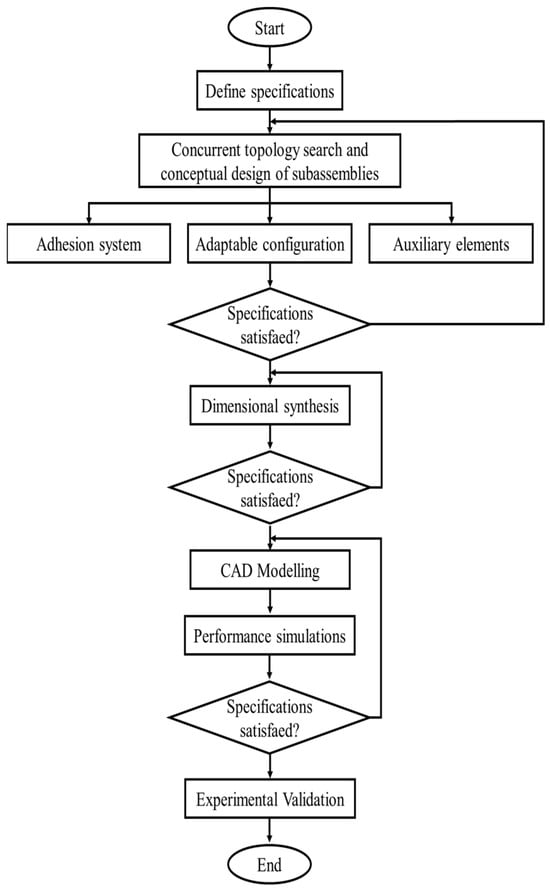
Figure 1.
Flow chart of the design of the robot.
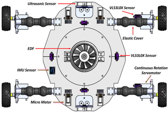
Figure 2.
Top view of the proposed wheeled-legged robot.
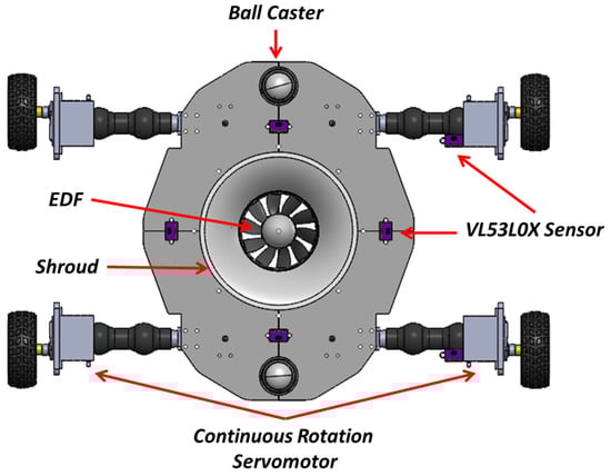
Figure 3.
Bottom view of the proposed wheeled-legged robot.
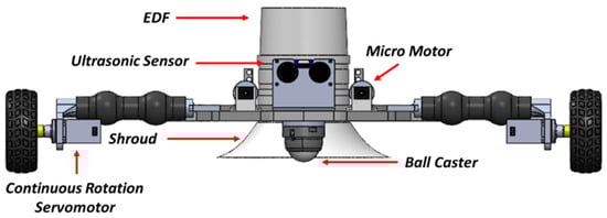
Figure 4.
Front view of the proposed wheeled-legged robot.
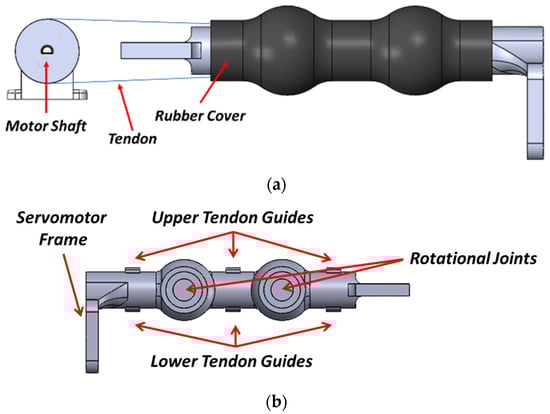
Figure 5.
Main parts of the proposed legs: (a) general view, (b) particular view.
At the center of the body is located an EDF as the vortex system. The wheeled-legged configuration has three main proposes: (1) to provide faster and easier displacement of the robot by using the wheels, (2) to adapt to the different irregularities and reliefs of the surface by using the legs, and (3) to vary the distance between the shroud of the vortex system and the surface. Thus, the robot can easily adapt to almost any part of the vertical surfaces. Also, two ball casters are mounted at the ends of the body to give major support to the robot, as well as to give a constant gap between the shroud of the vortex system and the surface. Different sensors are located along the robot to validate its adaptability and performance. The main dimensions of the robot are presented in Figure 6 and Figure 7. Figure 8 presents a photograph of the built robot.
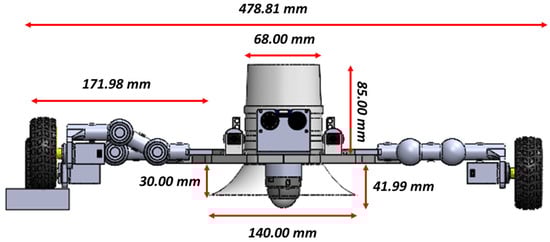
Figure 6.
Main dimensions of the robot: front view.
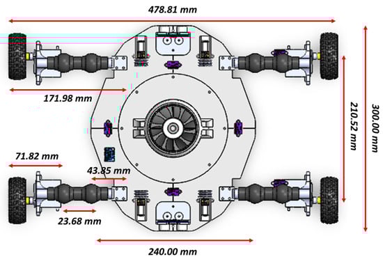
Figure 7.
Main dimensions of the robot: top view.
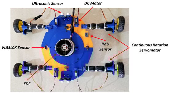
Figure 8.
Photograph of the built robot.
3. Analysis and Modeling of the Proposed Concept
3.1. Kinematic Analysis of Legs
In underactuated mechanisms (UMs), where the number of actuators is less than the degree of freedom (DoF), uncontrollable motions and forces occur to communicate passively with the physical world, such as complying with robotic hands in the form of grasped objects [14] and adapting with walking robots to complex road conditions [11]. The use of this kind of mechanisms for adaptative movements produces quite efficient and interesting results, since with low-quality sensory information the UM can easily adapt to the shape of any object. The proposed legs are composed by an underactuated mechanism and a wheel at its end extremity. The leg is considered a single tendon-driven articulated mechanism, where the joint values can be found by considering the principle for transmission lines and coaxiality in tendon-driven mechanisms [13,14,15]. This principle denotes that the links are labeled sequentially from 0 to n and the pulleys are labeled from j to j + n − 1. Considering the schematic diagram of the leg presented in Figure 9, the angular displacement of link j with respect to link i can be denoted by ; thus, the fundamental circuit equation, once for each pulley pair, is represented by Equation (1). The sign of each term of in Equation (1) is determined by the orientation of the routing: it is negative if it is a crossed routing; otherwise, it is positive [11]. The angular displacement of each the leg is denoted by Equation (2).
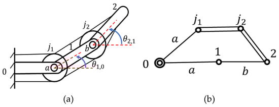
Figure 9.
Diagram of the leg: (a) schematic, (b) graph.
3.2. Mechanical Adaptability
The mechanical adaptability of a UM is defined as the ability to adapt or take the shape of an object by holding it. This capacity can be quantified as presented in Equation (3), where is the change in the joint’s position, and is the change in the generated torque. Adaptability, , is defined as the relationship between the joint state q and the external restrictions, which generate a change in the torque of the mechanism. Therefore, adaptability is the relationship between the articular movement of the mechanism and the torque generated until reaching a point of lock where the mechanism cannot move anymore [28,32,33]. Due to the above, the mechanical adaptability of the proposed legs is studied. The schematic diagram of the leg for mechanical adaptability is presented in Figure 10, where are the radio of each rotational joint, are the angular displacements of each joint, is the resistance of the rubber acting over each joint as a spring, and is the displacement of the tendon. The relationship between the deformation of the elastic elements, , given by the displacement of the actuator, , and the angles of the joints, , is denoted by Equation (4) [34]. Thus, the elastic potential energy of the mechanism can be expressed as in Equation (5). The relationship of change between the joint movement and the torque, or the generated force, is expressed by the second partial derivative of Equation (4), as presented in Equation (6) [17].
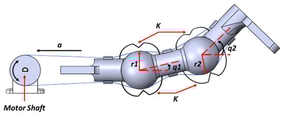
Figure 10.
Diagram of the proposed underactuated leg.
In the first instants of movement of the mechanism, before contacting the surface, it is free and without external constraints of movements, so the torque generated to be adapted is zero. When the mechanism contacts the surface, a matrix or vector of external constraints must be considered that allows evaluating its movement. The restricted movement of the mechanism, given the joint state, can be represented as Equation (7), where is the matrix of restrictions and is the restricted movement. Thus, consider a linear constraint in joint space, as expressed in Equation (8), where c represents the restricted joint positions of the mechanism.
Therefore, by solving Equation (6), the elements of the adaptability equation can be obtained:
Considering the parameters of the leg, presented in Table 3, the mechanical adaptability is simulated for a circular surface with radii of 250 mm. The behavior of the adaptability allows knowing the range of movement of the mechanism; the top value of the adaptability, when the mechanism can move without producing any force over the surface; and the lower value of adaptability, when the mechanism cannot move anymore and is producing the higher value of torque over the surface [28,34,35,36,37,38,39].
Table 3.
Parameters of one leg.
3.3. Vortex System
EDFs have been traditionally popular for their use as a propulsion method for both big and small-scale aircrafts, mainly due to an increased thrust efficiency by the reduction of the ducts of tip vortices and the pressure drops at the blade tips [40,41,42]. Thus, EDFs do not require the adhesion mechanism to be in contact with the target surface, which solves the design challenges of adhesion in cases of curved, rough, or nonferromagnetic surfaces [40,41,42,43,44]. In addition, no external equipment (e.g., compressor, tubes etc.) must be used for maintaining adhesion, which produces an easy operating solution.
The experimental evaluation of this adhesion system has been constrained to investigating the effect of the gap, i.e., the distance of the EDF shroud to the target surface, on the adhesion efficiency. Negative pressure adhesion works on the principle of generating and maintaining a low-pressure zone, , inside a cavity compared to the surrounding outside pressure, , and is the air flow velocity into . As depicted in Figure 11, the difference in pressure will induce a force, , across the projected cavity area onto the target surface, A, by the high-pressure region [42,43,44] as follows:
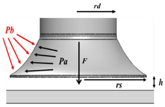
Figure 11.
Shroud detailed view with highlighted pressure zones and basic geometrical properties.
Considering an EDF-based adhesion mechanism, the low-pressure zone lies within its shroud; hence, the active pressure area is depicted in Equation (13).
Furthermore, air flow through the low-pressure zone, , is introduced by the distance between the shroud’s end and the test surface, h, as displayed in Figure 11. In addition to the adhesion force produced through the negative pressure, the EDF generates a thrust as it pulls air through the duct. At small h, the air density will not be enough to create a big thrust force, but as the gap increases and airflow is less restricted, the generated thrust will increase. Different simulations have been carried out through the CFD (computational fluid dynamics) of SolidWorks 2022 SP5 to evaluate the EDF equations (see Figure 12) considering the barometric pressure of the city of Queretaro in Mexico, its mean temperature, and the parameters in Table 4. CFD simulations demonstrate that over a 10 mm gap, the suction force begins to fall. Table 4 presents the simulation parameters. Simulation results are presented in Table 5.
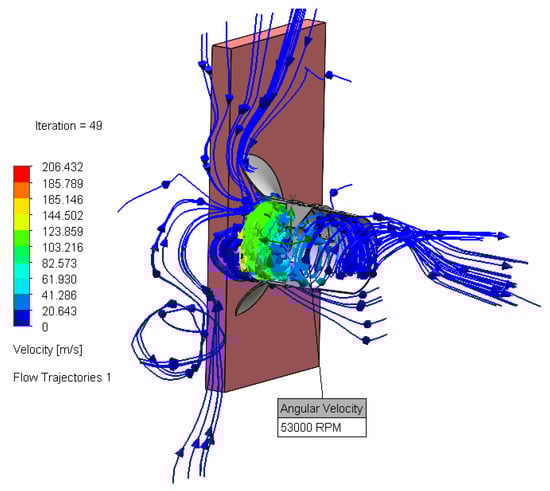
Figure 12.
CFD simulation through SolidWorks.
Table 4.
EDF parameters for simulations.
Table 5.
Simulation results.
3.4. Rolling Resistance Analysis
When a wheel runs over a flexible surface, it finds out resistance to the movement, since the surface immediately ahead is deforming. This phenomenon is called rolling resistance. Figure 13 shows a wheel with a vertical load, W, and a horizontal force, P, that produces the wheel to move with a constant velocity. The reaction pressure from the surface over the wheel passes through point B at the contact area (see Figure 13). Since the speed of the wheel is constant, the three forces acting on it are in equilibrium; therefore, the surface reaction R over the wheel must pass through the center of the wheel, O. The above generates the following moments in B.
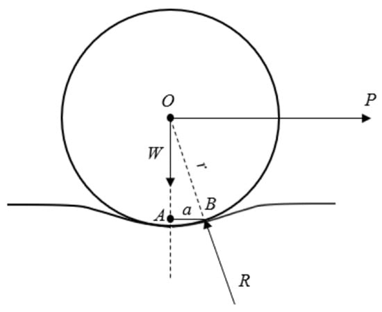
Figure 13.
Rolling of a wheel over a deformable surface.
Thus, the force P is equal to the horizontal component of the reaction R and is called rolling friction or rolling resistance; the distance a is called the coefficient of rolling resistance. The rolling friction or rolling resistance (f) for a sloping surface is given by the following:
Considering the free body diagram of Figure 14, the following equation is obtained:
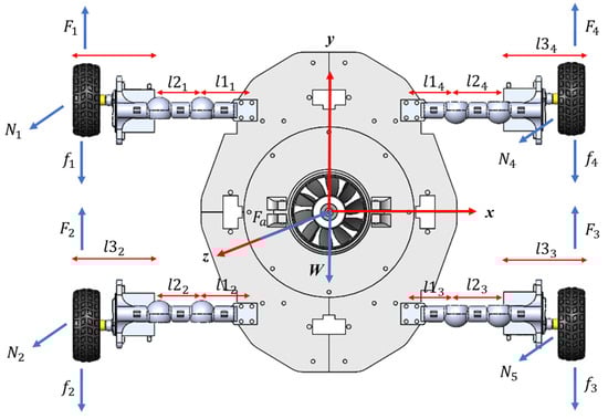
Figure 14.
Free body diagram of the robot.
Thus, the force F and the minimum required torque are defined in Equation (17) and Equation (18). Table 6 and Table 7 present the robot parameters and the static analysis results, respectively.
Table 6.
Robot parameters for static analysis.
Table 7.
Results for static analysis.
4. Experimental Evaluation
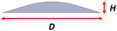
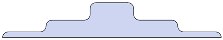
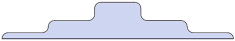
An experimental evaluation of the robot has been carried out to demonstrate its feasibility and features over a controlled environment. The experimental evaluation consists in evaluating the performance of the proposed robot during a vertical locomotion over a concrete wall. To validate the performance, ten different tests were carried out; each test was performed with a different obstacle. Table 8 presents the proposed experimental tests and the obstacle used in each one. Test 1 is used as reference test, with no obstacle and a free vertical locomotion, to compare it with the other tests. Figure 15, Figure 16, Figure 17 and Figure 18 present the desired behavior of the robot, and adaptation to obstacles, during the experimental tests.
Table 8.
Proposed tests for experimental evaluation of the robot.
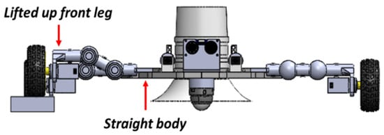
Figure 15.
Frontal view of the robot during the test.
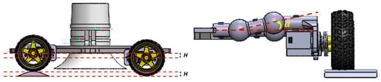
Figure 16.
Adaptation of the leg to the shape of the obstacle.
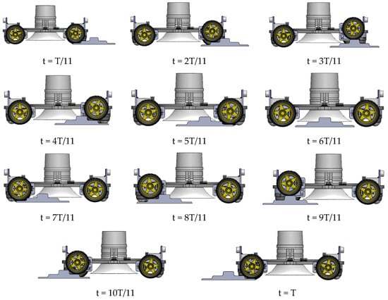
Figure 17.
CAD simulation of time lapse of the robot during test number 3, considering a period of time T.
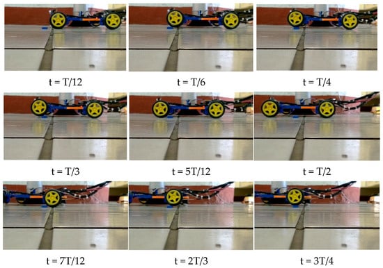
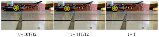
Figure 18.
Time lapse of the robot during a horizontal displacement for an obstacle of test number 6, considering a period of time T.
A LiPo battery (6s) is used as the main power supply of the robot; a voltage regulator allows setting a voltage of 5 volts to operate an Arduino UNO and the servomotors (MG995); an ESC controller is used to control the speed of the EDF; and a servo tester regulates the PWM to the ESC controller (see Figure 19). MG995 servomotors are used to drive the wheels, with a maximum torque of 15 kg-cm. Different sensors have been mounted over the robot to test its efficiency. An IMU sensor (GY-87) is mounted over the body to obtain the behavior of the angular displacements along the tests; thus, one can obtain the rotation during a straight, forward displacement. An ultrasonic sensor (HC-SR04) is mounted in the front of the body of the robot; thus, one can obtain its linear velocity by the relation between the displaced distance and the time lapse. Four laser sensors are located over the body to measure the distance between the body and the surface. One laser sensor is mounted over the servomotor of each leg (see Figure 1); thus, the distance between the leg and the wall can be measured. The above allows relating the displacement of the leg and the displacement of the body along the experimental tests; namely, it is possible to measure the adaptability of the robot when it is carrying out a vertical locomotion over different obstacles. Unlike the mechanical adaptability of UMs, this approach allows measuring the percentage that the leg is complying to the obstacle’s shape. Figure 20 and Figure 21 present a time lapse of the robot during the experimental evaluation for tests one and four, respectively. To measure the adaptability of the robot over the obstacles Equation (19) is used, where is the relative error between the theoretical high and the experimental high. The theoretical high is the sum of the distance of the leg to the wall (61 mm) and the high of the obstacle. The experimental high is the sensed distance between the leg and the wall.
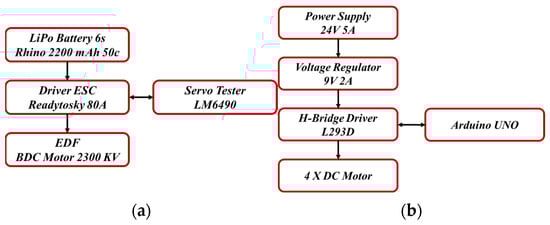
Figure 19.
Flow chart of the setup for experimental tests: (a) EDF, (b) mobile base.
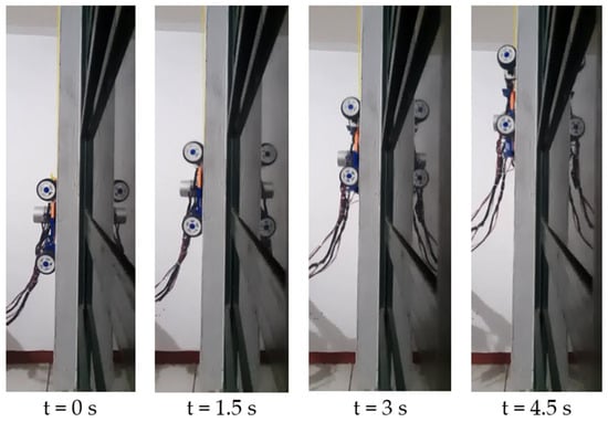
Figure 20.
Time lapse of test 1.
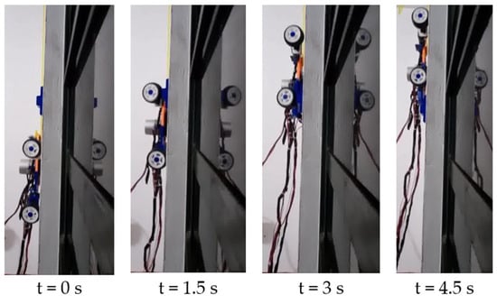
Figure 21.
Time lapse of test 4.
There are four representative tests used to demonstrate the feasibility of the robot, tests 2, 4, 5, and 10. The distance between the body and the wall during these three representative tests is presented in Figure 22, where it is possible to note that the body stays always parallel to the wall with a continuous distance of 52 mm with a variation of ±1 mm. Figure 23 presents the behavior of the legs during the representative tests. It is possible to appreciate that the legs of the robot are reaching the maximum high of each obstacle, according with Table 8. Therefore, if the body of the robot keeps straight and parallel to the wall, and if the legs are taking the shape of the obstacles, the robot is adapting into the shape of the obstacles during its vertical locomotion. The angular displacements, obtained with the IMU, are presented in Figure 24. Roll and pitch are the angular displacements for the x- and y-axis, respectively. The variation in the behavior of these axes is mainly due to the vibrations of the EDF; meanwhile, yaw (z-axis) represents the turning of the robot due to the vertical locomotion and the adaptability to the obstacles. Comparing Figure 23 and Figure 24, one can note that the variation in the angular displacements coincides with the movement of the legs during the test, (see Figure 23a and Figure 24a. Table 9 presents the summary of the experimental results of the robot. Table 10 presents the average measured values of the robot performance. To obtain the mean power consumption, an ACS712 current sensor has been used. The maximum power consumption, considering the servomotor and dc motor, is 1.54 watts for each leg; therefore, for the four legs it is 6.16 watts. Moreover, for the vortex system, the mean power consumption of the EDF is 1900 watts. Thus, the mean total power consumption of the robot is 1906.16 watts. Table 11 presents the statistical data of the carried out experimental evaluation.
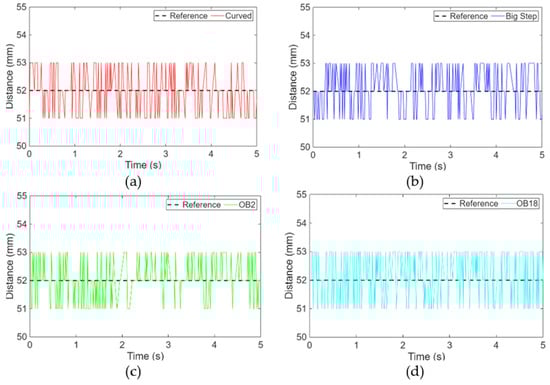
Figure 22.
Experimental results of the behavior of the body during the experimental evaluation for the representative tests: (a) test 2, (b) test 4, (c) test 5, (d) test 10.
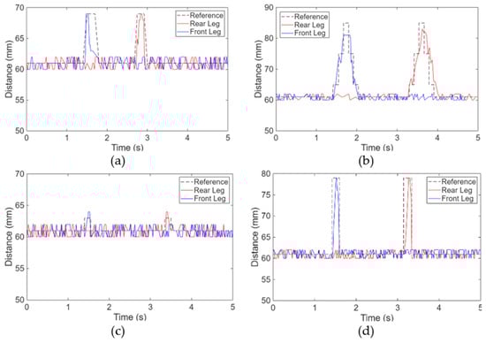
Figure 23.
Experimental results of the behavior of the legs during the experimental evaluation for the representative tests: (a) test 2, (b) test 4, (c) test 5, (d) test 10.
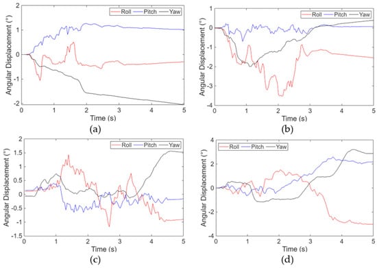
Figure 24.
Experimental results of the behavior of the legs during the experimental evaluation for the representative tests: (a) test 2, (b) test 4, (c) test 5, (d) test 10.
Table 9.
Summary of experimental results.
Table 10.
Average measured values of the proposed robot performance.
Table 11.
Statistical data of the experimental evaluation.
5. Conclusions
This paper presents the design of a novel wheeled-legged service robot for vertical locomotion tasks. The design of the robot allows displacing over concrete walls by using wheels, and the underactuated legs with rubber cover help the robot to adapt to almost any irregularity and relief of the surface. The robot uses an EDF as the vortex system for adhesion. This vortex system is located at the middle of the robot body. The use of the theory of mechanical adaptability for UMs gives a general perspective of the behavior of the legs during a grasping task. The use of UMs instead of fully driven mechanisms helps the robot to have legs with a higher adaptability with an easier control strategy. The EDF simulations demonstrate the feasibility of the proposed configuration since, by varying h and the EDF speed, the suction force can support the required load and weight specifications of the robot. Different sensors have been used to compare the performance of the robot on each test, mainly the adaptability of the legs in respect of the main body. The experimental tests demonstrate that the wheels follow the shape of the obstacles during vertical locomotion; meanwhile, the main body of the robot keeps straight and parallel to the climbing surface, with an average relative error of 0.00684 and an adaptability of 99.316%.
Author Contributions
Conceptualization, E.C.O.-M., E.C.-C., and G.C.; methodology, E.C.-C. and G.C.; investigation, E.C.O.-M.; mechanical design, E.C.O.-M., E.C.-C., and G.C.; writing—original draft preparation, E.C.O.-M.; writing—review and editing, E.C.O.-M., E.C.-C., G.C., and O.R.-A.; visualization, E.C.-C. and G.C.; supervision, E.C.-C. and G.C.; project administration, E.C.-C.; funding acquisition, E.C.-C. All authors have read and agreed to the published version of the manuscript.
Funding
This research was partially supported by CONHACYT, the National Council of Humanities, Sciences and Technologies of Mexico, supporting the corresponding author with a PhD grant during he studies. CVU grant number: 788543.
Data Availability Statement
The raw data supporting the conclusions of this article will be made available by the authors on request.
Acknowledgments
The first author wishes to thank CONHACYT for a grant which supported him along his PhD studies.
Conflicts of Interest
The authors declare no conflicts of interest.
References
- Orozco-Magdaleno, E.C.; Cafolla, D.; Castillo-Castañeda, E.; Carbone, G. A Service Hexapod Robot as Hospital Guide. Int. J. Mech. Control 2019, 20, 121–126. [Google Scholar]
- Orozco-Magdaleno, E.C.; Cafolla, D.; Castillo-Castañeda, E.; Carbone, G. Static Balancing of Wheeled-legged Hexapod Robots. Robotics 2020, 9, 23. [Google Scholar] [CrossRef]
- Carbone, G.; Tedeschi, F.; Gallozzi, A.; Cigola, M. A Robotic Mobile Platform for Service Tasks in Cultural Heritage. Inter-Natl. J. Adv. Robot. Syst. 2015, 12, 88. [Google Scholar] [CrossRef]
- García-Rodríguez, G.M.; Castillo-Castañeda, E. A Robot for Facade Cleaning Based on a Cartesian Configuration: Kinematic Analysis and Prototype Construction. In Advances in Service and Industrial Robotics; Müller, A., Brandstötter, M., Eds.; RAAD 2022. Mechanisms and Machine Science; Springer: Cham, Switzerland, 2022; Volume 120. [Google Scholar] [CrossRef]
- Fang, Y.; Wang, S.; Bi, Q.; Cui, D.; Yan, C. Design and Technical Development of Wall-Climbing Robots: A Review. J. Bionic Eng. 2022, 19, 877–901. [Google Scholar] [CrossRef]
- Liu, Y.; Sun, S.; Wu, X.; Mei, T. A Wheeled Wall-Climbing Robot with Bio-Inspired Spine Mechanisms. J. Bionic Eng. 2015, 12, 17–28, ISSN 1672-6529. [Google Scholar] [CrossRef]
- Altaf, M.; Ahmad, E.; Xu, Y.; Liu, R.; Li, Y.; Na, H. Design of a climbing robot platform with protection device. Int. J. Adv. Rob. Syst. 2017, 14, 1729881417716382. [Google Scholar] [CrossRef]
- Schmidt, D.; Berns, K. Climbing Robots for Maintenance and Inspections of Vertical Structures—A Survey of Design Aspects and Technologies. Robot. Auton. Syst. 2013, 61, 1288–1305. [Google Scholar] [CrossRef]
- Drexler, J. Robot Workers with a Head for Heights. Fraunhofer Magazine, 2005; 34–35. [Google Scholar]
- Yoshida, Y.; Ma, S. Design of a Wall-Climbing Robot with Passive Suction Cups. In Proceedings of the International Conference on Robotics and Biomimetics, ROBIO, IEEE, Tianjin, China, 14–18 December 2010; pp. 1513–1518. [Google Scholar]
- Brockmann, W. Towards Low Cost Climbing Robots. In Proceedings of the 7th International Conference on Climbing and Walking Robots, CLAWAR, Madrid, Spain, 22–24 September 2004; Springer: Vienna, Austria, 2004; pp. 1–6. [Google Scholar]
- Orozco Magdaleno, E.C. Wall-Bot: The Hexapod Robot for Inspection. In Mecatrónica y Robótica de Servicio: Teoría y Aplicaciones; Capítulo 3; Asociación Mexicana de Mecatrónica A.C.: Santiago de Querétaro, Mexico, 2016. [Google Scholar]
- Wang, Y.; Liu, S.; Xu, D.; Zhao, Y.; Shao, H.; Gao, X. Development and Application of Wall-Climbing Robots. In Proceedings of the International Conference on Robotics and Automation, ICRA, Detroit, MI, USA, 10–15 May 1999; pp. 1207–1212. [Google Scholar]
- Clarifying Technologies. Clarifying Climber III—Remote Controlled Climbing Vehicle; Clarifying Technologies Inc.: Kirkland, DC, USA, 2005. [Google Scholar]
- Morris, W.; Xiao, J. City-Climber: Development of a Novel Wall-Climbing Robot. J. Stud. Res. 2008, 1, 40–45. [Google Scholar]
- Zhou, Q.; Xin, L. Experimental Investigation on Climbing Robot Using Rotation-Flow Adsorption Unit. Robot. Auton. Syst. 2018, 105, 112–120. [Google Scholar] [CrossRef]
- Saboori, P.; Morris, W.; Xiao, J.; Sadegh, A. Aerodynamic Analysis of City-Climber Robots. In Proceedings of the International Conference on Robotics and Biomimetics, Sanya, China, 15–18 December 2007; pp. 1855–1860. [Google Scholar]
- Sintov, A.; Avramovich, T.; Shapiro, A. Design and Motion Planning of an Autonomous Climbing Robot With Claws. Robot. Auton. Syst. 2011, 59, 1008–1019. [Google Scholar] [CrossRef]
- Spenko, M.J.; Haynes, G.C.; Saunders, J.A.; Cutkosky, M.R.; Rizzi, A.A.; Full, R.J.; Koditschek, D.E. Biologically Inspired Climbing with a Hexapedal Robot. J. Field Robot. 2008, 25, 223–242. [Google Scholar] [CrossRef]
- Prahlad, H.; Pelrine, R.; Stanford, S.; Marlow, J.; Kornbluh, R. Electroadhesive Robots—Wall Climbing Robots Enabled by a Novel, Robust, and Electrically Controllable Adhesion Technology. In Proceedings of the International Conference on Robotics and Automation, ICRA, Pasadena, CA, USA, 19–23 May 2008; pp. 3028–3033. [Google Scholar]
- Cui, G.; Liang, K.; Guo, J.; Li, H.; Gu, D. Design of a Climbing Robot Based on Electrically Controllable Adhesion Technology. In Proceedings of the International Conference on Solid State and Materials, ICSSM, Kyoto, Japan, 25–27 September 2012; Volume 22, pp. 90–95. [Google Scholar]
- Daltorio, K.A.; Horchler, A.D.; Gorb, S.; Ritzmann, R.E.; Quinn, R.D. A Small Wall-Walking Robot with Compliant, Adhesive Feet. In Proceedings of the International Conference on Intelligent Robots and Systems, IROS, Edmonton, AB, Canada, 2–6 August 2005; pp. 4018–4023. [Google Scholar]
- Unver, O.; Sitti, M. A Miniature Ceiling Walking Robot with Flat Tacky Elastomeric Footpads. In Proceedings of the 2009 IEEE International Conference on Robotics and Automation, Kobe, Japan, 12–17 May 2009; pp. 2276–2281. [Google Scholar]
- Rochat, F.; Hirschmann, V.; Barras, T.; Bleuer, H.; Mondada, F. Climbing Robot with Thermal Glue. In Proceedings of the 14th International Conference on Climbing and Walking Robots, CLAWAR, Paris, France, 6–8 September 2011; pp. 409–416. [Google Scholar]
- HB2 by HausBots. Available online: https://hausbots.com/hb2/ (accessed on 30 December 2024).
- Laliberté, T.; Gosselin, C.M. Simulation and design of underactuated mechanical hands. Mech. Mach. Theory 1998, 33, 39–57. [Google Scholar] [CrossRef]
- Chen, W.; Xiong, C.; Chen, W.; Yue, S. Mechanical adaptability analysis of underactuated mechanisms. Rob. Comp-Int. Man. 2018, 49, 436–447. [Google Scholar] [CrossRef]
- Birglen, L.; Laliberté, T.; Gosselin, C.M. Underactuated Robotic Hands; Springer: Berlin, Germany, 2008. [Google Scholar]
- Santello, M.; Flanders, M.; Soechting, J.F. Postural hand synergies for tool use. J. Neurosci. 1998, 18, 10105–10115. [Google Scholar] [CrossRef]
- Dalley, S.A.; Wiste, T.E.; Withrow, T.J.; Goldfarb, M. Design of a multifunctional anthropomorphic prosthetic hand with extrinsic actuation. IEEE/ASME Trans. Mechatron. 2009, 14, 699–706. [Google Scholar] [CrossRef]
- Hirose, S.; Umetani, Y. The development of soft gripper for the versatile robot hand. Mech. Mach. Theory 1978, 13, 351–359. [Google Scholar] [CrossRef]
- Chen, W.; Xiong, C.; Liu, M.; Mao, L. Characteristics analysis and mechanical implementation of human finger movements. In Proceedings of the IEEE International Conference on Robotics and Automation, Hong Kong, China, 31 May–7 June 2014; pp. 403–408. [Google Scholar]
- Bicchi, A.; Gabiccini, M.; Santello, M. Modelling natural and artificial hands with synergies. Philos. Trans. R. Soc. Lond. B Biol. Sci. 2011, 366, 3153–3161. [Google Scholar] [CrossRef]
- Balasubramanian, R.; Dollar, A.M. A comparison of workspace and force capabilities between classes of underactuated mechanisms. In Proceedings of the IEEE International Conference on Robotics and Automation, Shanghai, China, 9–13 May 2011; pp. 3489–3496. [Google Scholar]
- Chen, W.; Xiong, C. On Adaptive Grasp with Underactuated Anthropomorphic Hands. J. Bionic Eng. 2016, 13, 59–72. [Google Scholar] [CrossRef]
- Chen, W.; Xiong, C.; Yue, S. Mechanical implementation of kinematic synergy for continual grasping generation of anthropomorphic hand. IEEE/ASME Trans. Mecha Tronics 2015, 20, 1249–1263. [Google Scholar] [CrossRef]
- Ozawa, R.; Kobayashi, H.; Hashirii, K. Analysis, classification, and design of tendon driven mechanisms. IEEE Trans. Robot. 2014, 30, 396–410. [Google Scholar] [CrossRef]
- Brusell, A.; Andrikopoulos, G.; Nikolakopoulos, G. Vortex Robot Platform for Autonomous Inspection: Modeling and Simulation. In Proceedings of the IECON 2019—45th Annual Conference of the IEEE Industrial Electronics Society, Lisbon, Portugal, 14–17 October 2019; pp. 756–762. [Google Scholar] [CrossRef]
- Xiao, J.; Sadegh, A.; Elliott, M.; Calle, A.; Persad, A.; Chiu, H.M. Design of Mobile Robots with Wall Climbing Capability. In Proceedings of the 2005 IEEE/ASME International Conference on Advanced Intelligent Mechatronics, Monterey, CA, USA, 24–28 July 2005; pp. 24–28. [Google Scholar]
- Sekhar, P.; Bhooshan, R. Duct Fan Based Wall Climbing Robot for Concrete Surface Crack Inspection. In Proceedings of the IEEE India Conference (IN-DICON), Pune, India, 11–13 December 2014. [Google Scholar]
- Zhao, J.; Li, X.; Bai, J. Experimental study of vortex suction unit-based wall-climbing robot on walls with various surface conditions. Proc. Inst. Mech. Eng. J. Mech. Eng. Sci. 2018, 231, 3977–3991. [Google Scholar] [CrossRef]
- Andrikopoulos, G.; Nikolakopoulos, G. Vortex Actuation via Electric Ducted Fans: An Experimental Study. J. Intell. Robot. Syst. 2018, 95, 955–973. [Google Scholar] [CrossRef]
- Brusell, A.; Andrikopoulos, G.; Nikolakopoulos, G. Novel Considerations on the Negative Pressure Adhesion of Electric Ducted Fans: An Experimental Study. In Proceedings of the 25th Mediterranean Conference on Control and Automation (MED), Valletta, Malta, 3–6 July 2017. [Google Scholar]
- Guan, Y.; Zhu, H.; Wu, W.; Zhou, X.; Jiang, L.; Cai, C.; Zhang, L.; Zhang, H. A Modular Biped Wall-Climbing Robot with High Mobility and Manipulating Function. IEEE/ASME Trans. Mechatron. 2013, 18, 1787–1798. [Google Scholar] [CrossRef]
Disclaimer/Publisher’s Note: The statements, opinions and data contained in all publications are solely those of the individual author(s) and contributor(s) and not of MDPI and/or the editor(s). MDPI and/or the editor(s) disclaim responsibility for any injury to people or property resulting from any ideas, methods, instructions or products referred to in the content. |
© 2025 by the authors. Licensee MDPI, Basel, Switzerland. This article is an open access article distributed under the terms and conditions of the Creative Commons Attribution (CC BY) license (https://creativecommons.org/licenses/by/4.0/).