1. Introduction
Robotic-assisted minimally invasive surgery (RAMIS), particularly with systems like the da Vinci surgical system, has revolutionized surgery by offering enhanced precision, control, and dexterity [
1]. However, the cognitive and physical demands placed on surgeons during these procedures can lead to significant fatigue, which can pose risks to patient safety [
2]. Medical errors are the third leading cause of death in the US [
3]. Most errors during robotic surgery are due to poor visualization, decision making, inadvertent tool movements, and potentially surgeon fatigue. In these complex systems, the surgeon is removed from the extensive sensory experience of the remote site (e.g., visual, auditory, and tactile), resulting in reduced situational awareness and a high mental workload. Surgeon fatigue has emerged as a critical issue in the field of robotic surgery, where the precision and sophistication of technologies like the da Vinci surgical system demand intense concentration and skill from surgeons. Fatigue can impair a surgeon’s ability to maintain the high levels of concentration and motor control required for successful outcomes. Addressing this challenge is critical as robotic surgery becomes more prevalent in clinical practice [
4]. In addition, because the surgery tools, surgeon hand controllers, the surgeon’s eye movements, and even posture can be easily monitored, fatigue detection in robotic surgery could be easier to track than traditional laparoscopy surgery.
Surgeon fatigue in RAMIS encompasses both physical and cognitive dimensions, resulting from the intense focus, extended procedure durations, and the complexity of operating advanced surgical systems [
5]. Physical fatigue can manifest as musculoskeletal strain due to non-ergonomic positions maintained during surgery, while cognitive fatigue is associated with the high mental workload (cognitive overload) required for precise control and decision making under pressure. These two are interrelated and can influence each other.
The absence of sensory feedback in robotic systems further exacerbates these challenges, as surgeons must rely heavily on visual inputs, often leading to visual strain and reduced alertness over time. Additionally, the repetitive nature of camera adjustments and tool manipulations adds to the cognitive load, making fatigue management a crucial aspect of surgical safety [
5,
6,
7].
This study focuses on developing and verifying a real-time fatigue monitoring system designed to address these issues. By tracking key indicators such as instrument collisions, blink rate, and workspace utilization, the system provides immediate feedback to surgeons, potentially helping to prevent fatigue-related errors and enhancing the safety of robotic surgeries.
1.1. Background
Fatigue in this context encompasses not only physical tiredness but also cognitive and emotional exhaustion, which can significantly impair a surgeon’s ability to perform effectively. The prolonged duration of surgeries, the need for fine motor control, and the cognitive load of managing complex machinery interact to heighten fatigue levels, which in turn can jeopardize patient safety and surgical outcomes [
8].
Sleep deprivation also impairs cognitive function and motor precision. Using a robotic surgical simulator, Robison et al. have demonstrated that fatigue negatively impacted performance metrics after sleep-deprived situations of continuous operation [
9]. These findings suggest that mental fatigue compounds physical strain, potentially compromising surgical accuracy. While no statistically significant differences in robotic skills were found between fatigued and non-fatigued groups, subjective fatigue levels influenced residents’ learning curves, emphasizing the nuanced relationship between fatigue and cognitive performance.
The systematic review by Wee et al. expands on the issue of fatigue by exploring the ergonomic challenges inherent in robotic surgery systems [
8]. The review criticizes the current ergonomic designs of surgical robots, which often place physical strain on surgeons, leading to fatigue and discomfort. The authors call for a reevaluation of these designs, suggesting that enhancing ergonomic features could reduce fatigue and improve both surgeon welfare and performance.
A pivotal study by Mark et al. underscores the detrimental impact of fatigue on surgical training, particularly among urology residents using the da Vinci Surgical Skills Simulator. The research demonstrates that residents who are post-call or have had insufficient rest show relatively poor performance on the simulator, characterized by slower task completion and higher error rates [
4]. This finding is crucial as it highlights the potential risks to learning and skill development, suggesting that fatigue can significantly undermine the training process, which is foundational to developing surgical competence.
The work of Ohnishi et al. introduces a novel approach to managing surgeon fatigue through wearable sensors [
10]. This study tests the feasibility of using real-time monitoring devices to assess fatigue levels during robotic surgery. The sensors aim to provide objective data on a surgeon’s physical state, which could be used to prompt breaks or adjustments in surgery schedules. In addition, Wang et al. also review wearable sensors for various use cases [
11]. While the concept is promising, these approaches differ from our approach of not using any wearable sensors. These approaches require careful calibration of additional sensors integrated into the surgical workflow to ensure that it supports, rather than disrupts, surgical procedures [
12]. Fatigue monitoring via passive sensors or with the tools already used (as we have proposed here) rather than sensors that may require extra calibration or even adjustment during surgeries is desirable and potentially less disruptive.
1.2. What Should We Measure?
Based on current research, the fatigue monitoring system we propose includes specific metrics designed to provide a comprehensive understanding of the surgeon’s fatigue levels. These metrics include (1) instrument collisions, (2) blink rates, and (3) master workspace utilization.
Instrument Collisions: This metric tracks the frequency of unintended contacts between the surgical tools, which can indicate a lapse in coordination or a decline in cognitive function due to fatigue. An increase in such collisions during procedures may suggest that the surgeon is experiencing significant fatigue, impacting their motor skills and attention to detail [
4]. The study by Cumpanas et al. investigates the effect of fatigue on surgeons’ performance during extended robotic surgical procedures [
13]. Using a virtual reality simulator, the study demonstrated that surgeons’ skills deteriorate significantly over a continuous four-hour session. This decline was notably marked by worsening scores in several specific metrics, which initially improved in the first hour but fell as the session continued. Instrument collision was one of the metrics used to measure the impact of fatigue. The choice of this metric is pertinent because it directly relates to the precision and control that surgeons must maintain during operations. Collisions can indicate a lapse in concentration or a decline in fine motor control, both of which are likely to be affected by fatigue. This metric is crucial for assessing the safety and efficacy of surgical procedures, as increased collision rates during surgeries can lead to operational errors and complications.
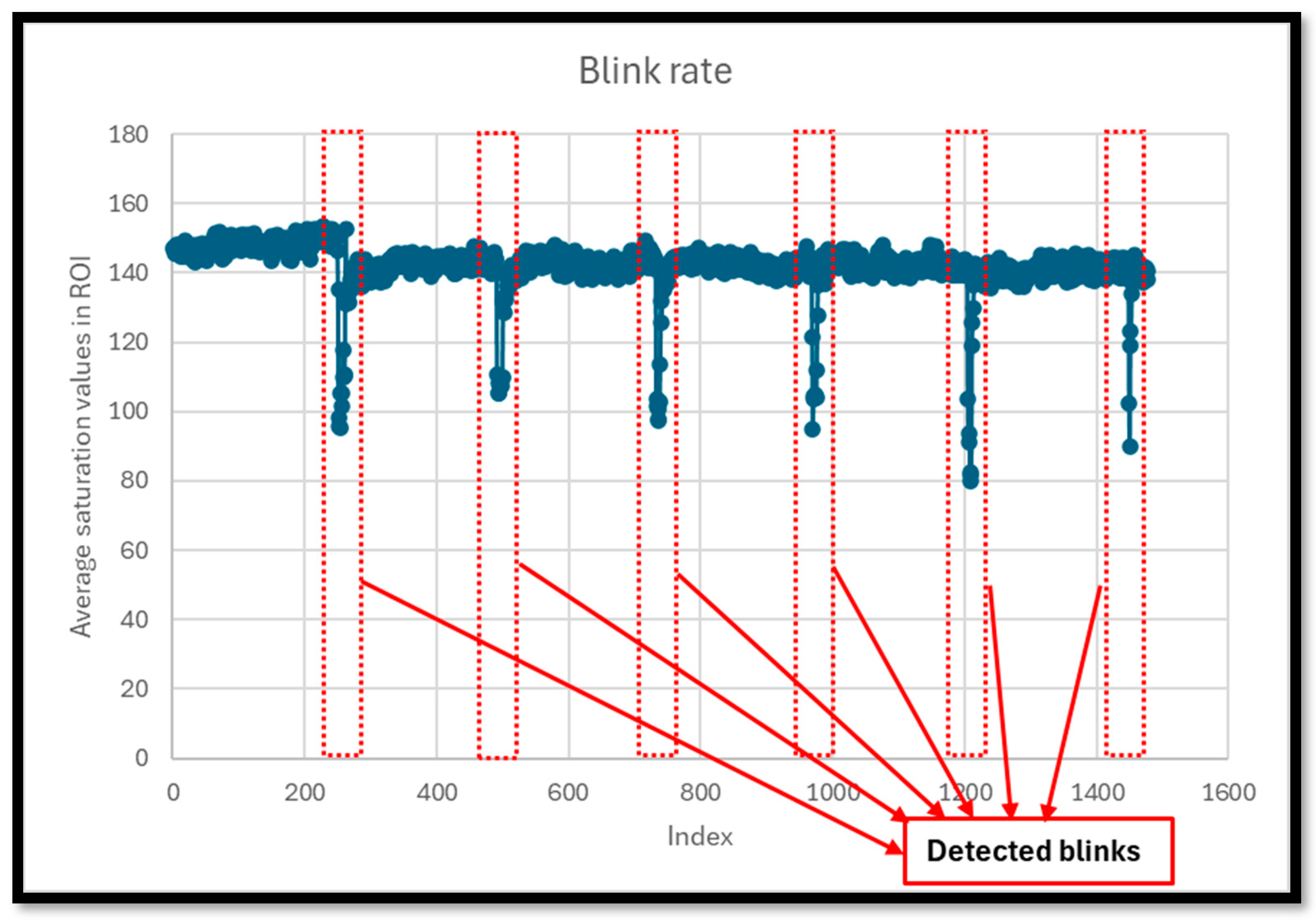
Blink Rate: Monitoring the blink rate of a surgeon offers insights into their level of alertness. Research indicates that fatigue can lead to a slower blink rate followed by phases of rapid blinking as a person tries to regain alertness and focus. By tracking changes in blink patterns, the system can provide early warnings of fatigue, allowing for timely interventions. Blink rate is a significant indicator of eye strain and fatigue. Under normal conditions, blinking helps to lubricate the eyes, ensuring comfort and clarity of vision. However, in visually demanding tasks that require sustained attention, such as operating the da Vinci system, blink rate can decrease, leading to dry eyes, discomfort, and increased fatigue. This response is an involuntary physiological reaction to high cognitive load and focus, making blink rate an excellent proxy for measuring visual and cognitive fatigue in surgeons during complex surgical procedures [
14].
Master Workspace Utilization: This metric evaluates how effectively a surgeon uses the available workspace on the master console of the robotic system. Efficient use of this space is often linked to optimal ergonomic posture and reduced physical strain. Deviations in typical workspace utilization patterns can indicate physical fatigue or discomfort, prompting adjustments to improve ergonomics and reduce the risk of fatigue-related errors. Master workspace utilization is a critical factor in determining the ergonomic efficiency and overall effectiveness of surgeons operating robotic systems like the da Vinci surgical system. The master workspace in robotic surgical systems refers to the physical and virtual environment where the surgeon interacts with the robotic controls to execute surgical procedures. Proper utilization of this space by clutching the foot pedals and recentering the hand controllers is crucial, as it directly affects the surgeon’s ability to perform tasks with precision and comfort. An optimal workspace allows for natural movements that mimic the surgeon’s hands, reducing the physical strain that often leads to fatigue. Studies have shown that improved ergonomic conditions in the master workspace correlate with lower levels of reported fatigue and discomfort among surgeons [
15]. Efficient workspace utilization also impacts surgical performance. When surgeons operate in an ergonomically optimized environment, they are less likely to experience fatigue, which can degrade cognitive functions critical for complex decision making and motor control.
These metrics are selected based on their ability to offer real-time, relevant, and objective feedback on a surgeon’s physical and cognitive state during robotic surgeries. In addition, no sensors need to be worn and calibrated by the surgeon. A simple camera and access to hand-controller kinematics are all that is needed.
2. Materials and Methods
2.1. Overview of the da Vinci Surgical System
The da Vinci surgical system is a revolutionary medical technology designed to facilitate minimally invasive surgery across various medical specialties [
1]. Developed by Intuitive Surgical, Inc. (Sunnyvale, CA, USA), the system provides surgeons with enhanced precision, dexterity, and control while performing complex surgical procedures. This overview will delve into the components, functionality, applications, advantages, and limitations of the da Vinci surgical system.
There are three main components of the da Vinci surgical system. The first component is the surgeon console, where the surgeon sits during the procedure. It consists of ergonomic hand and foot controls, as well as a stereoscopic vision system that provides a high-definition, 3D view of the surgical site. The hand controls are commonly referred to as the master tool manipulators (MTMs). The second component is the patient cart, which is positioned near the operating table and holds the robotic arms equipped with surgical instruments. These arms are referred to as the patient-side manipulators (PSMs), and they mimic the movements of the surgeon’s hand with remarkable precision. The third component is the vision/controller cart, which serves as the system’s computational and control hub. It integrates advanced image processing hardware and software to manage the high-definition video feed, ensuring real-time, clear, and consistent visual feedback to the surgeon. Additionally, this cart houses the system’s core processors, FPGAs, and low-level control algorithms, which interpret the surgeon’s inputs from the MTMs and translate them into precise, scaled movements of the PSMs. This unit is crucial for the seamless integration and synchronization of the system’s components, ensuring operational efficiency and surgical precision.
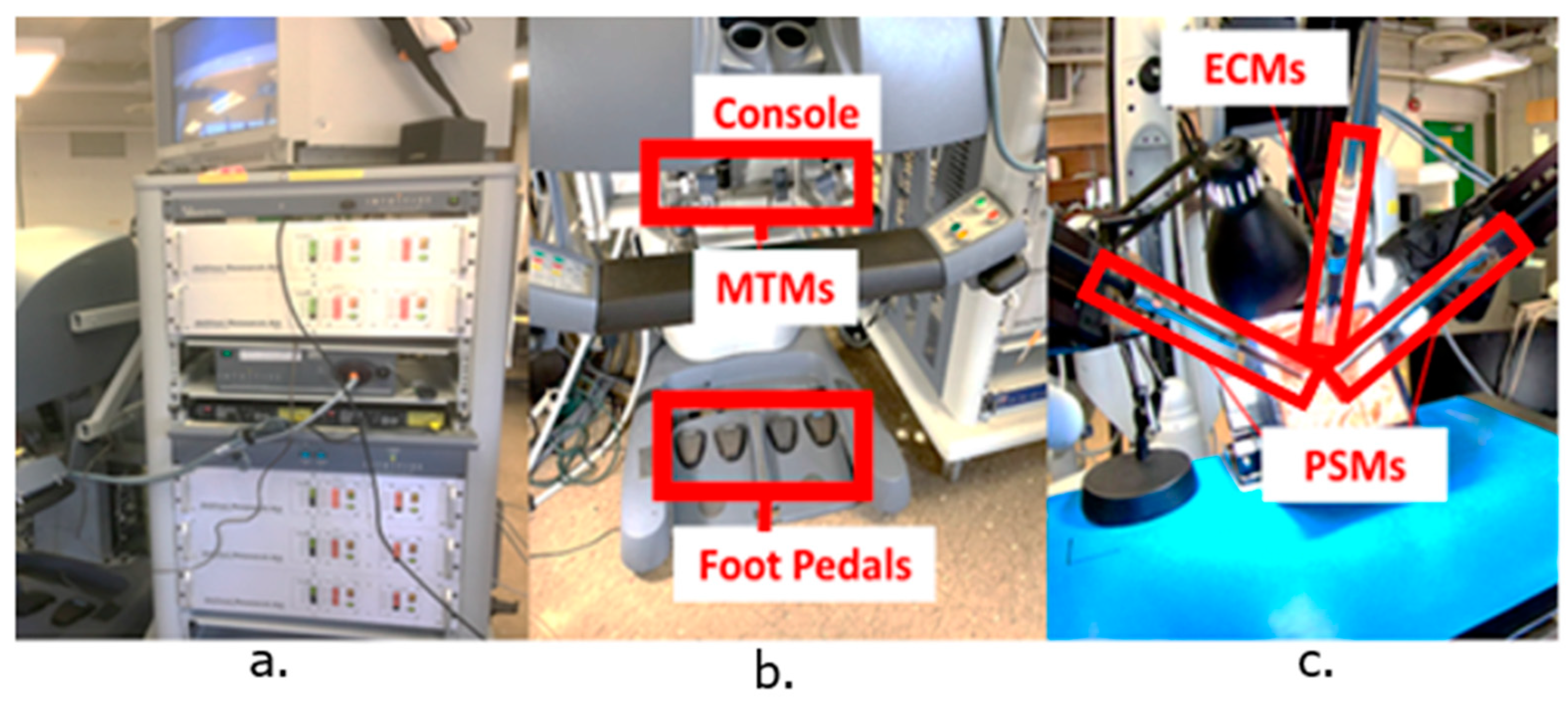
Figure 1 depicts the three components of the standard da Vinci surgical system at our research lab.
The system operates in a leader-follower configuration, where the surgeon’s hand movements at the console are translated into precise movements of the robotic arms and instruments inside the patient’s body.
2.2. The da Vinci Research Kit (dVRK) and the Robot Operating System
The da Vinci Research Kit (DVRK) supplies the control hardware and corresponding ROS software interfaces necessary for operating the da Vinci Standard robot hardware [
16]. The Robot Operating System (ROS) is an open-source framework designed primarily for robotics programming. It serves as middleware that provides a suite of services crucial for robotics applications, such as hardware abstraction, low-level device control, message-passing, and package management. Its core strengths lie in its modularity, allowing developers to segment complex functionalities into manageable packages and nodes, and its vast array of tools and libraries that aid in the construction, deployment, and management of robust applications.
2.3. Fatigue Detection Software
The overall software architecture was designed to support a continuous and automated monitoring of operator fatigue, crucial for ensuring safety in environments involving intensive human-robot interaction. The system centers around a major ROS node, implemented within the “MainSafety” class, which orchestrates the operations of three additional ROS nodes dedicated to the real-time assessment of specific fatigue-related metrics: instrument collisions, blink rate, and master workspace utilization.
Figure 2 depicts the overall architecture for the fatigue monitoring system.
2.3.1. Instrument Collisions
The implementation of the ROS node to analyze this specific metric relied heavily on the DVRK [
16]. The corresponding script integrates several ROS nodes and utilizes Python 3 libraries for mathematical calculations and time-based operations. The script is structured around the subscription to multiple ROS topics that broadcast the state of various robotic components, such as joint states and Cartesian positions of two patient-side manipulators (PSM1 and PSM2), and includes callback functions that are invoked upon receiving messages on these topics.
The joint states for each manipulator are as follows:
where,
The Cartesian positions of both tools are computed with their respective forward kinematics algorithms as follows:
where,
: Cartesian end-effector positions (e.g., [x, y, z]) for PSM1 and PSM2
and, are the forward kinematic transformations
The velocity, acceleration, and jerk are computed as follows:
Then, the distance collision check is made as follows
potential collision proximity is triggered.
Then the jerk check is made
abrupt motion is flagged (indicating sudden or uncontrolled movement).
Finally, a collision or near collision event is checked as follows:
Both distance and jerk must exceed critical limits to register a collision event are tunable safety parameters.
Key functionalities of the script revolve around the continuous monitoring of the robot’s operational parameters—specifically positions, velocities, and potential collisions. The callback functions “psm1_desired_callback”, “psm1_current_callback”, “psm2_desired_callback”, and “psm2_current_callback” are crucial as they handle real-time data of each manipulator’s desired and actual joint states. These functions update global variables that track the current and desired positions of the joints, which are used to assess motion and positional discrepancies that could indicate deviations or errors in manipulator movements.
The script also monitors Cartesian positions through “psm1_cartesian_pos_callback” and “psm2_cartesian_pos_callback”, updating respective buffers that store these positions over time. These data are instrumental in the “calculate_collision” function, which predicts and detects potential collisions based on the manipulators’ trajectories and velocities. These functions use differential calculations to monitor the tool’s movements. By calculating the first, second, and third derivatives of position (velocity, acceleration, and jerk, respectively), the script can detect sudden changes in motion, which are often precursors to unsafe conditions [
17].
Collision detection is further refined by considering the transformed positions of both manipulators. These positions are compared, and if the distance between the manipulators falls below a threshold (indicative of a potential collision), and if the jerk exceeds a certain parametrizable limit (indicating abrupt or uncontrolled motion), the script logs this event and alerts the main ROS node.
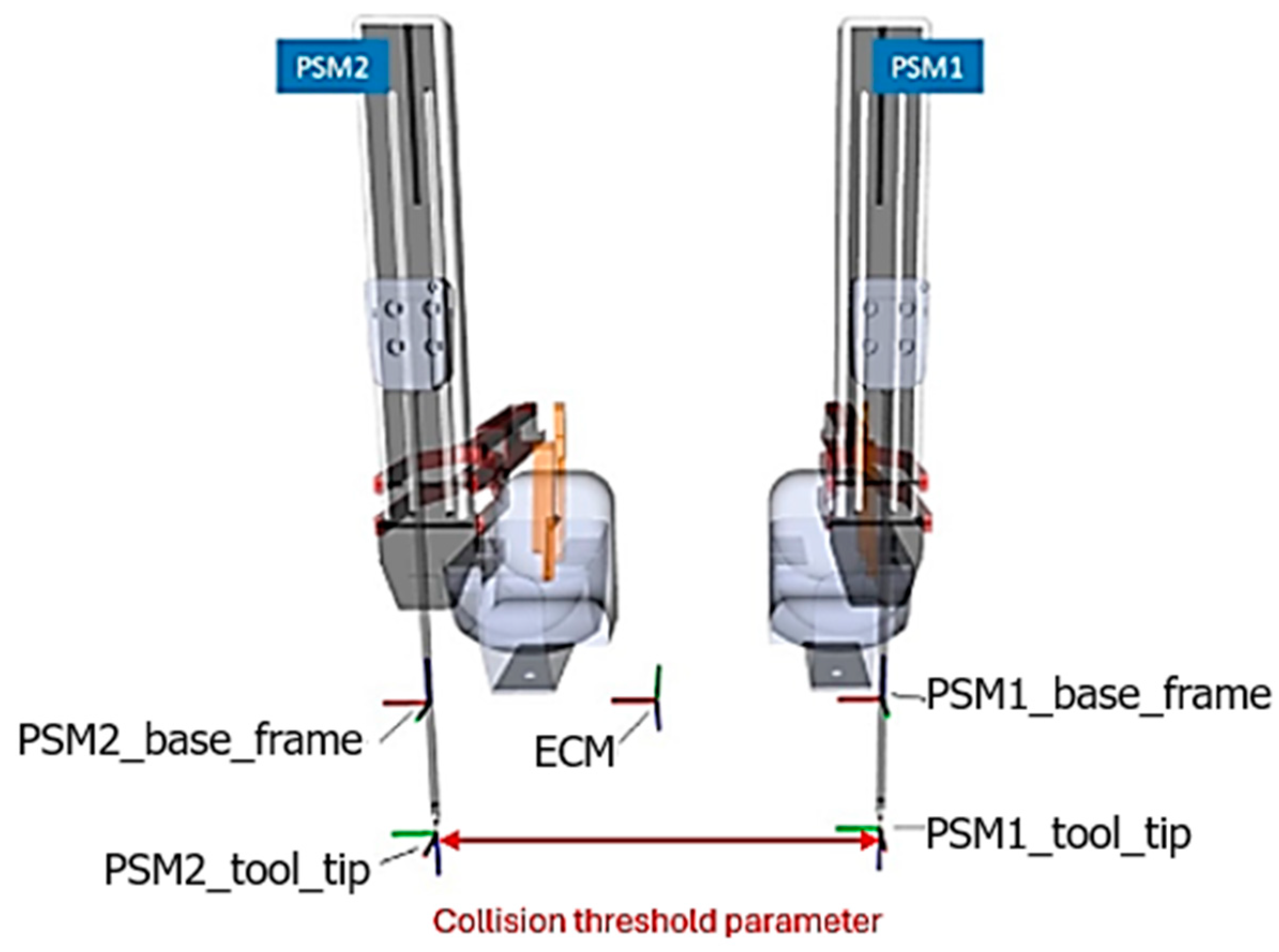
Figure 3 and
Figure 4 depict the different coordinate frames for each PSM and the threshold parameter for collision detection. The implementation ensures robustness and responsiveness by leveraging ROS’s messaging capabilities. Through subscribing to relevant topics and publishing on the “/safety/psm” topic, the script communicates critical safety information.
2.3.2. Blink Rate
The measurement of blink rate involved an integration of computer vision techniques and ROS communication functionalities to monitor and quantify blinks in video streams. The overall goal of this ROS node was to process video inputs to detect blinking patterns and publish the results through an ROS topic. The primary utilities employed in this implementation include the OpenCV library for image processing tasks and the ROS framework for handling real-time data publishing. Such a setup is particularly pertinent in scenarios where real-time monitoring of human physiological responses is required to assess alertness and fatigue.
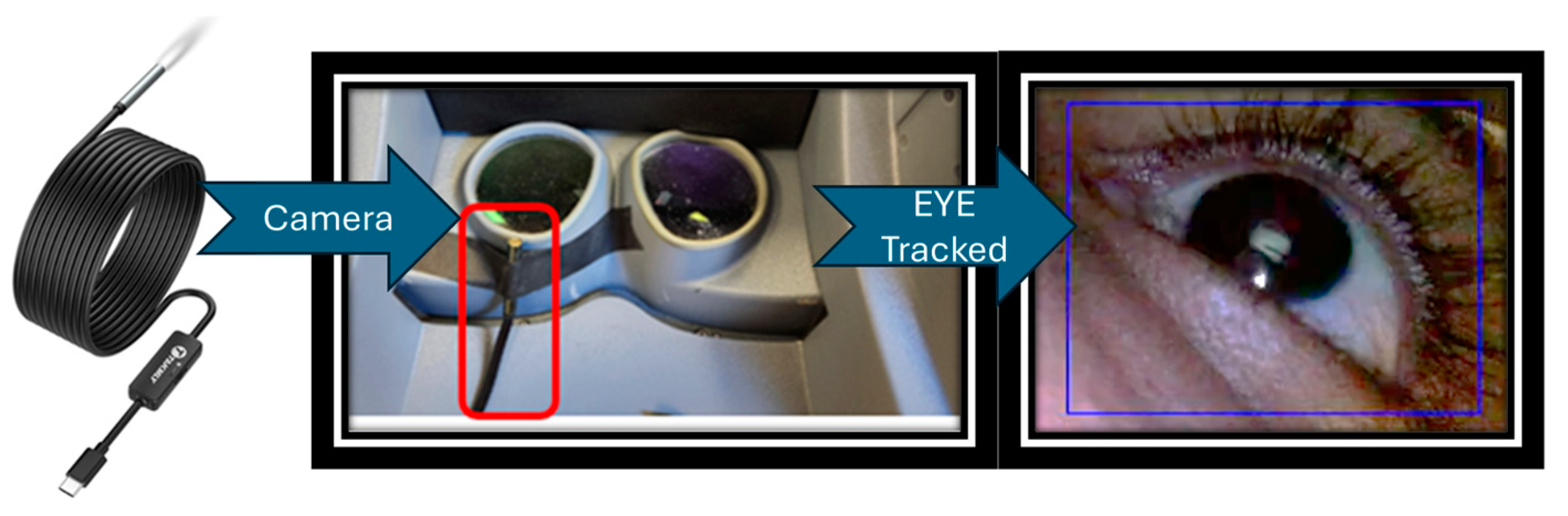
During the initialization phase, the “BlinkDetector” class sets up the video processing infrastructure and ROS communication pathways. It initializes a ROS node and establishes a publisher that will broadcast the count of detected blinks to a main overall ROS topic. Video capture is configured to fetch data from a specified source (an external camera pictured in
Figure 5). The script allows for manual selection of a region of interest (ROI) through “cv2.selectROI”, typically around the eyes, to focus the blink detection efforts. This selected area is used to initialize tracking objects that maintain focus on the region throughout the video processing, ensuring accurate blink detection.
Figure 5 also depicts the ROI selection.
The “run” method orchestrates the frame-by-frame video processing. Each frame is captured from the video source and is subjected to a series of transformations, including rescaling and conversion to hue, saturation, value (HSV) color space. The saturation channel, extracted during this conversion, is instrumental as it enhances the visibility of features pertinent to detecting blinks, such as those associated with human skin and eyes.
The script utilizes “cv2.TrackerCSRT”, a robust tracking algorithm, to track the defined ROI across frames [
18]. As each frame is processed, the script updates the position of the ROI and visually annotates the tracked area along with its surroundings on the output video, aiding in both debugging and operational oversight. Blink detection is based on analyzing the average pixel intensity within the ROI. A significant drop in this average, below a predefined threshold, signals a blink. This detection is contingent on changes in pixel distribution caused by the eye’s closure. Let each video frame at time
t be denoted by
. The bounding box/region of interest (ROI) at frame
t is given by
, where
is the top-left corner and
are the width and height. The CSRT tracker updates this bounding box in each new frame
, producing
Once the bounding box is updated, the average pixel intensity
in that ROI is computed:
where
is the total number of pixels in the region defined by
. Finally, a blink is detected if this mean intensity drops below a predefined threshold
:
Equations (4)–(6) summarize how each frame is updated and how a drop in average pixel intensity within that ROI signals an eye blink. The value of
is parameterized.
Figure 6 depicts a frame-by-frame tracking of the eye during a blink.
Upon detecting a blink, the script increments a counter and temporarily disables further detection to avoid counting the same blink multiple times. This mechanism is controlled through a “blink_trigger” flag that resets once the pixel intensity returns above the threshold, readying the system for subsequent detections. Each blink detected triggers a publication event on a ROS topic, seamlessly integrating this data into the broader monitoring ROS node.
2.3.3. Master Workspace Utilization
The primary function of this feature was to monitor the utilization of the master workspace by measuring how much of the available range of motion is being used during a procedure [
19]. It establishes a ROS node that subscribes to encoders within the MTM, gathering real-time data critical for maintaining operational precision during surgical procedures. The script is particularly focused on detecting and responding to positional deviations, termed “centroid drift”, and involved calculating the relative movement of the MTM controls within their maximum allowable limits.
Upon initialization, the script sets up ROS subscribers to capture real-time positional data from the robotic system’s sensors. Callback functions (“left_gripper_callback” and “right_gripper_callback”) are designed to update the positions of each gripper continually. Importantly, these functions establish the initial positions of the grippers, which are used to calculate an initial centroid position. This initial centroid serves as a baseline for detecting deviations throughout the surgical procedure and is calculated using the midpoint formula.
Another function “calculate_centroid” scheduled to run at regular intervals via a ROS timer, is pivotal to the script’s operation. It ensures that the initial centroid is accurately established based on the first received positions of the grippers. Subsequently, this function calculates the current centroid during each execution cycle and compares it against the initial centroid to identify any positional drift. A predefined threshold (“centroid_drift_threshold”) currently set to 5 cm is used to determine significant deviations, with any change beyond this threshold flagged as a drift.
Position vectors
represent the 3D coordinates of the left and right gripper tips at time
t.
The initial centroid
is established from the first received positions (
), forming the baseline for comparison.
The current centroid
at any time
t is simply the midpoint of the two gripper positions.
The centroid drift
measures how far the current centroid has moved relative to the initial centroid.
If the magnitude of this drift exceeds a predefined threshold
τ (e.g., 5 cm), the system flags it as significant positional deviation or “centroid drift”.
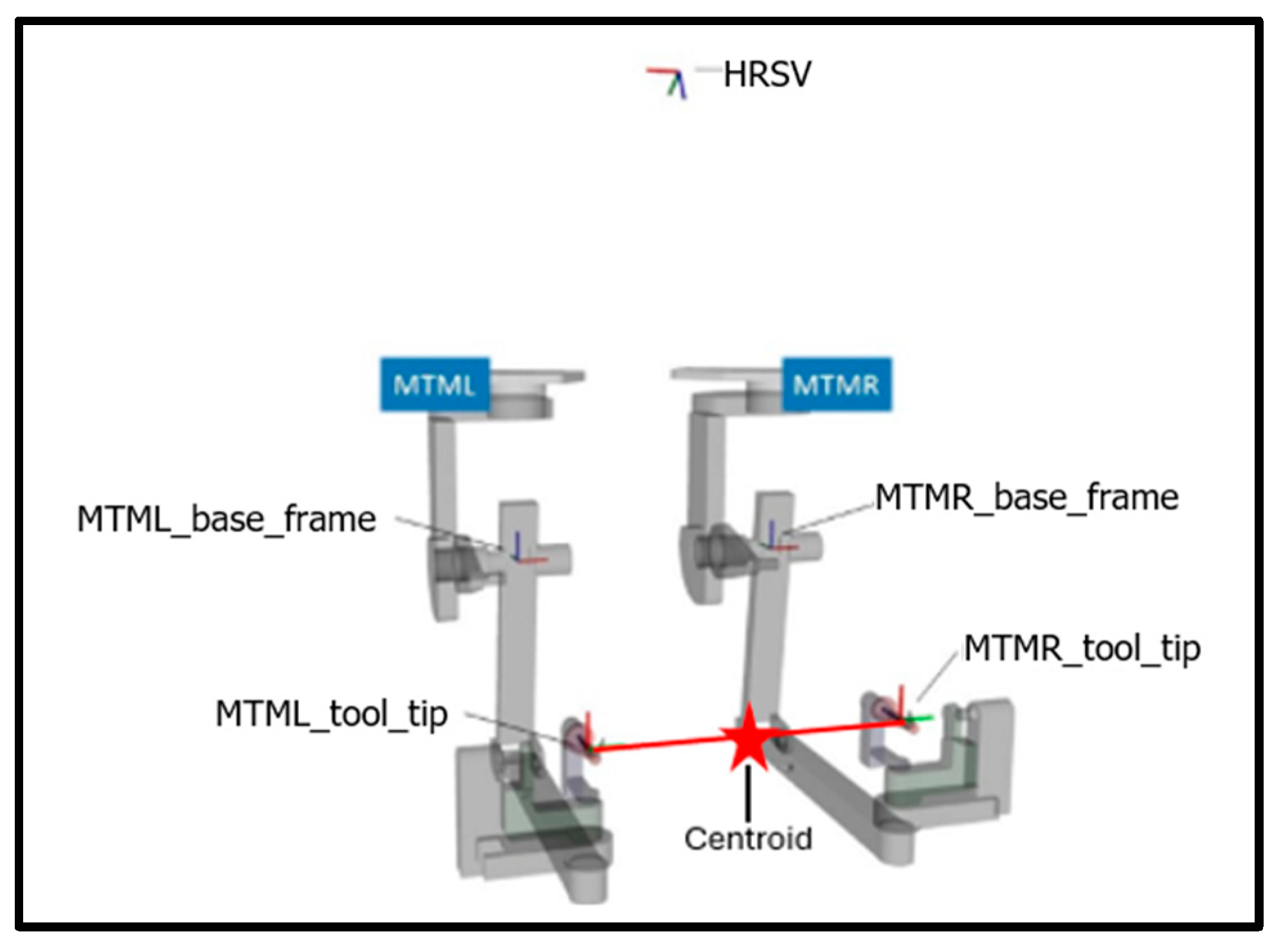
Figure 7 and
Figure 8 depict the coordinate frames of the MTMs and the location of the centroid.
The script not only detects drifts but also quantifies them through a total drift count, which it then publishes to a ROS topic (“/safety/mtm”). This publication allows the main ROS monitoring node to utilize the data for alerting operators, and possibly initiating corrective measures, or conducting post-operative analysis. Such a mechanism enhances the system’s capability to monitor itself in real time and integrates well into broader safety protocols, maintaining the integrity and precision of the surgical procedure.
The clutch foot pedal input from the surgeon is integrated into the system through additional ROS subscribers (“clutch_callback”). These inputs allow the surgeon to interact directly with the monitoring system, particularly through the clutch, which enables manual resetting of the drift count. This feature effectively distinguishes between intentional repositioning by the surgeon and unintended drifts, enhancing the system’s responsiveness to real operational contexts.
Figure 9 depicts instances of centroid drift at the surgeon console.
2.4. A Simple System Verification
In an initial system verification (using just one of the authors), we deliberately simulated both normal and fatigued conditions to verify that the system software provided accurate alerts. No participants were recruited. Specifically, we altered our blinking patterns to mimic fatigue, intentionally collided instruments, and operated the hand-controller at the extreme workspace edges of its range—three behaviors the software tracks as key indicators. We then observed if under normal operation and typical blink rates, the system issued no alerts to normal, expected behaviors. We then observed the system when we exhibited signs of fatigue and non-optimal movements to see if the software correctly recognized these conditions and generated the appropriate notifications.
2.5. Use of ChatGPT
We would also like to acknowledge that ChatGPT (GPT-4-turbo) was used in the following way to improve the English and flow of this paper. After certain paragraphs were outlined and written, ChatGPT was asked to improve the written English and not to edit the meaning of the paragraph. Each such paragraph was then checked to make sure the content remained as intended. This was used much like spell checkers or grammar editors are used to improve the document. The ideas and content remain ours.
3. Results
The fatigue monitoring system designed for the da Vinci surgical system has shown promising results in identifying key fatigue indicators crucial for ensuring the safety and efficacy of surgical procedures. The system effectively integrates various metrics such as instrument collisions, blink rate, and master workspace utilization, providing a comprehensive overview of potential fatigue-related errors during surgery.
Our initial findings indicate that each fatigue indicator can be effectively monitored in real time, offering potential for early detection of surgeon fatigue. The system’s ability to track instrument collisions has proven particularly effective. Increased collision rates and high acceleration were accurately identified. The blink rate monitoring also demonstrated potential, with noticeable changes in blink patterns correlating with simulated fatigued patterns. Similarly, master workspace utilization data provided insights into ergonomic practices during surgery. Deviations from typical utilization patterns were effectively detected, indicating possible physical strain or suboptimal ergonomic positioning, which could lead to increased fatigue over time.
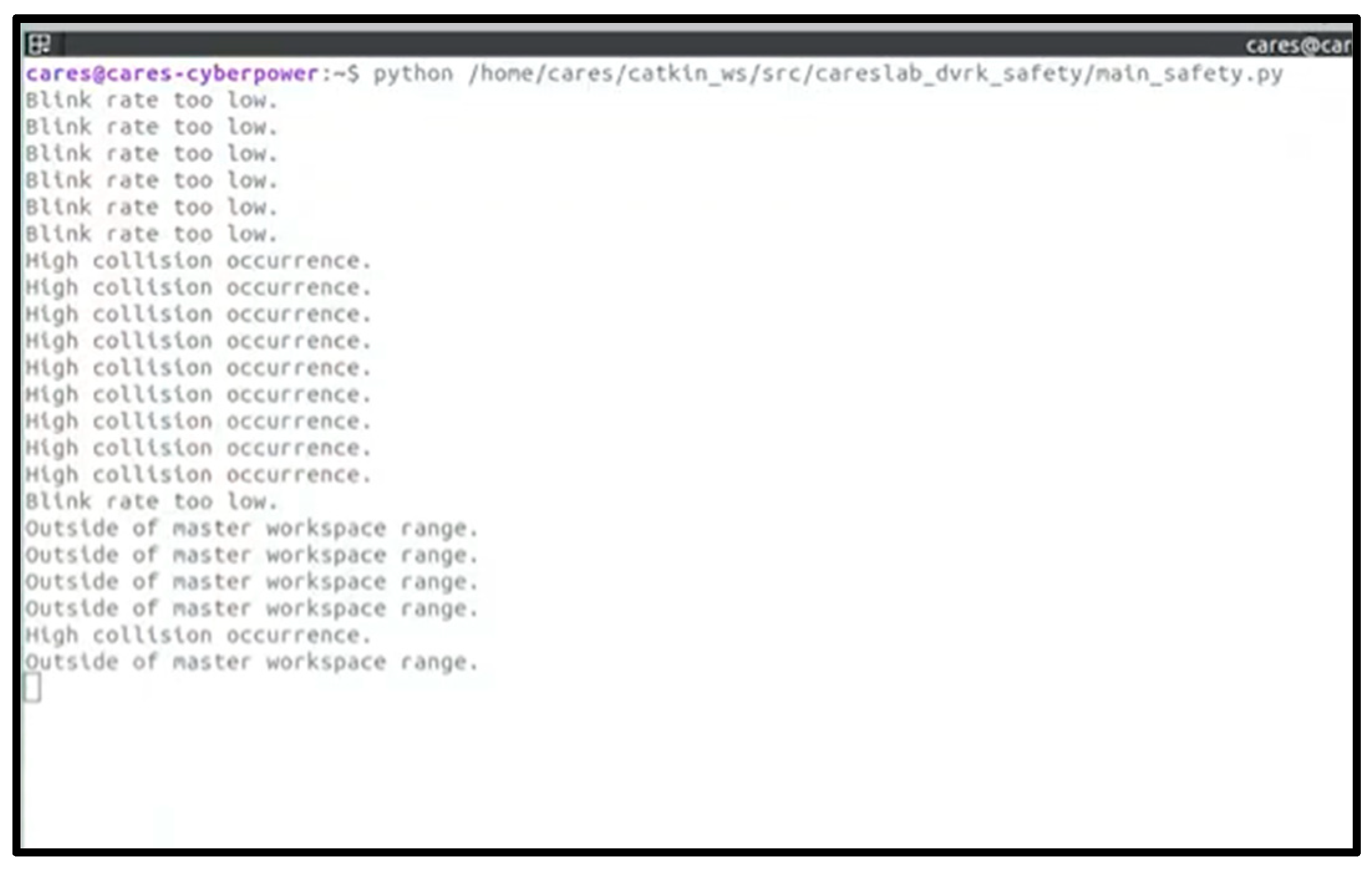
Figure 10 depicts the terminal output with the main safety ROS node.
Figure 11,
Figure 12 and
Figure 13 present the results obtained from monitoring the master workspace, operator blink rate, and PSM collisions.
4. Discussion
While the system has demonstrated its functional capabilities, there is a clear need for comprehensive user studies to evaluate its effectiveness in a clinical setting. In addition, there are limitations of the system as we apply it to a clinical setting, including issues related to real-time performance, false alarm rates, and surgical and environmental interference. Surgeon adoption could also be an issue. Although real-time performance is not an issue (as fatigue detection can occur over minutes of data collection), the false alarm rate must be carefully considered such that alarm fatigue does not set in. Hence, surgeon feedback is crucial to refine the system’s parameters and ensure its practical utility without interfering with the surgical workflow.
Moreover, the integration of objective physiological measurements, such as heart rate variability (HRV) or EEG, could enhance the system’s accuracy in detecting fatigue. HRV is a well-recognized indicator of physiological stress and could provide a quantifiable measure of stress and fatigue levels, complementing the subjective indicators currently used [
20]. To enhance the precision and reliability of our fatigue monitoring system, incorporating infrared reflectance oculography presents a significant improvement over the current methods of blink rate monitoring [
21]. Infrared reflectance oculography is a more sophisticated and sensitive technique for tracking eye movements and blink patterns. This technology can offer finer detail and greater accuracy in measuring the subtle changes in eye behavior associated with fatigue, making it an invaluable tool for real-time fatigue assessment. These types of wearable sensors should be integrated and calibrated to be seamless and not an additional hindrance to the surgeon. Otherwise, we risk making the system more complex and a barrier to adoption.
5. Conclusions
In conclusion, while the fatigue monitoring system shows significant promise in enhancing surgical safety through proactive monitoring, its full potential can only be realized through further clinical validation and the integration of comprehensive objective measurements. This will ensure that the system not only detects fatigue accurately but also supports surgeons in maintaining optimal performance throughout their procedures.
The development of a real-time fatigue monitoring system marks a significant step forward in improving the safety and efficiency of robotic surgery. By providing surgeons with immediate feedback on their fatigue levels, the system can help prevent errors and ensure better surgical outcomes. In addition, future robotic systems could even gradually alter their movement and control parameters (e.g., speed of tools, motion scaling, etc.) to compensate for surgeon fatigue and to help avoid accidental or abrupt movement and prevent errors.
The intent of this paper was to showcase the relatively new idea of surgeon monitoring for robotics surgery. The next phase of research will involve trials to validate the system’s effectiveness and explore the integration of artificial intelligence (AI) tools to further enhance its capabilities. To see how mental overload affects surgeons, we will recruit participants to perform increasingly challenging robotic surgery simulator tasks—such as suturing or peg transfers—while handling additional demands like an N-back memory test (e.g., counting backwards from 100 by 4′ s) or distracting OR noises. Throughout each session, we will record EEG signals to capture moments of rising stress or fatigue. We will use the EEG data as a ground-truth indication of cognitive overload just for training the AI. Simultaneously, we will measure the passive performance metrics like tool movement smoothness, error rates, eye-tracking data (including blink rates and pupil dilation), and workspace utilization. By training an AI system with these paired data (cognitive overload (as determined by EEG) and passive performance metrics), we aim to identify subtle “fatigue signatures” that reveal exactly when a surgeon’s cognitive capacity is reaching its limit using only the passive sensors. This approach will help us develop better strategies to predict and mitigate fatigue in real-world surgical environments without disrupting the current surgical workflow by adding in wearable sensors like the EEG sensor.
It is also envisioned that hospitals and surgical centers could establish protocols that leverage data from these monitoring systems to facilitate real-time decisions regarding surgical schedules and necessary breaks. This proactive approach is aimed at effectively managing surgeon fatigue, ensuring safety and efficiency.
Author Contributions
Conceptualization, A.P. and R.A.P.; methodology, R.A.P. and A.P.; software, R.A.P. and A.P.; validation, R.A.P.; formal analysis, R.A.P. and A.P.; investigation, R.A.P.; resources, A.P.; data curation, R.A.P.; writing—original draft preparation, R.A.P.; writing—review and editing, R.A.P. and A.P.; visualization, R.A.P.; supervision, A.P. All authors have read and agreed to the published version of the manuscript.
Funding
This research received no external funding.
Data Availability Statement
The data are available upon request.
Acknowledgments
We would like to thank David Edelman, a practicing robotic surgeon at the Detroit Medical Center, for his insight on the issue of fatigue during surgery. We would also like to thank Hao Ying and Xingyu Zhao for their discussion on AI methods of detecting fatigue. We would also like to acknowledge that we have used ChatGPT to improve the English flow of certain parts of the paper as described in the methods section.
Conflicts of Interest
The authors declare no conflicts of interest.
Abbreviations
The following abbreviations are used in this manuscript:
| RAMIS | Robotic-assisted minimally invasive surgery |
| MTM | Master tool manipulators |
| PSM | Patient-side manipulators |
| DVRK | da Vinci Research Kit |
| ROS | Robot Operating System |
| ROI | Region of interest |
| HRV | Heart rate variability |
| HSV | Hue, saturation, value |
References
- Sung, G.T.; Gill, I.S. Robotic laparoscopic surgery: A comparison of the da Vinci and Zeus systems. Urology 2001, 58, 893–898. [Google Scholar] [PubMed]
- Armijo, P.R.; Huang, C.-K.; Carlson, T.; Oleynikov, D.; Siu, K.-C. Ergonomics analysis for subjective and objective fatigue between laparoscopic and robotic surgical skills practice among surgeons. Surg. Innov. 2020, 27, 81–87. [Google Scholar]
- Makary, M.A.; Daniel, M. Medical error—The third leading cause of death in the US. BMJ 2016, 353, i2139. [Google Scholar] [CrossRef] [PubMed]
- Mark, J.R.; Kelly, D.C.; Trabulsi, E.J.; Shenot, P.J.; Lallas, C.D. The effects of fatigue on robotic surgical skill training in Urology residents. J. Robot. Surg. 2014, 8, 269–275. [Google Scholar] [CrossRef] [PubMed]
- Zheng, B.; Cassera, M.A.; Martinec, D.V.; Spaun, G.O.; Swanström, L.L. Measuring mental workload during the performance of advanced laparoscopic tasks. Surg. Endosc. 2010, 24, 45–50. [Google Scholar] [CrossRef] [PubMed]
- Berguer, R.; Forkey, D.; Smith, W. The effect of laparoscopic instrument working angle on surgeons’ upper extremity workload. Surg. Endosc. 2001, 15, 1027–1029. [Google Scholar] [CrossRef] [PubMed]
- Keehner, M.M.; Tendick, F.; Meng, M.V.; Anwar, H.P.; Hegarty, M.; Stoller, M.L.; Duh, Q.Y. Spatial ability, experience, and skill in laparoscopic surgery. Am. J. Surg. 2004, 188, 71–75. [Google Scholar] [PubMed]
- Wee, I.J.Y.; Kuo, L.J.; Ngu, J.C.Y. A systematic review of the true benefit of robotic surgery: Ergonomics. Int. J. Med. Robot. Comput. Assist. Surg. 2020, 16, e2113. [Google Scholar]
- Robison, W.; Patel, S.K.; Mehta, A.; Senkowski, T.; Allen, J.; Shaw, E.; Senkowski, C.K. Can fatigue affect acquisition of new surgical skills? A prospective trial of pre-and post-call general surgery residents using the da Vinci surgical skills simulator. Surg. Endosc. 2018, 32, 1389–1396. [Google Scholar] [CrossRef] [PubMed]
- Ohnishi, A.; Tohnan, H.; Terada, T.; Hattori, M.; Yoshinaka, H.; Sumi, Y.; Egi, H.; Tsukamoto, M. A Method for Estimating Doctor’s Fatigue Level in Operating a Surgical Robot Using Wearable Sensors. In Proceedings of the 2021 IEEE International Conference on Pervasive Computing and Communications Workshops and other Affiliated Events (PerCom Workshops), Kassel, Germany, 22–26 March 2021; pp. 38–43. [Google Scholar]
- Wang, X.; Yu, H.; Kold, S.; Rahbek, O.; Bai, S. Wearable sensors for activity monitoring and motion control: A review. Biomim. Intell. Robot. 2023, 3, 100089. [Google Scholar] [CrossRef]
- Takács, K.; Lukács, E.; Levendovics, R.; Pekli, D.; Szíjártó, A.; Haidegger, T. Assessment of Surgeons’ Stress Levels with Digital Sensors during Robot-Assisted Surgery: An Experimental Study. Sensors 2024, 24, 2915. [Google Scholar] [CrossRef]
- Cumpanas, A.; Bardan, R.; Ferician, O.; Latcu, S.C.; Lazar, O.; Duta, C. The impact of tiredness on virtual reality robotic surgical skills. Videosurg. Other Miniinvasive Tech. 2020, 15, 298–304. [Google Scholar] [CrossRef] [PubMed]
- Molle, F.; Savastano, M.C.; Giannuzzi, F.; Fossataro, C.; Brando, D.; Molle, A.; Rebecchi, M.T.; Falsini, B.; Mattei, R.; Mirisola, G.; et al. 3D Da Vinci robotic surgery: Is it a risk to the surgeon’s eye health? J. Robot. Surg. 2023, 17, 1995–2000. [Google Scholar] [CrossRef] [PubMed]
- Mendes, N.M.P.; Dogramadzi, S. Cognitive and Physical Effort of Surgeons Using Master/Slave Surgical Systems for Minimally Invasive Surgery. Master’s Thesis, Universidade de Lisboa, Lisboa, Portugal, 2020. [Google Scholar]
- Kazanzides, P.; Chen, Z.; Deguet, A.; Fischer, G.S.; Taylor, R.H.; DiMaio, S.P. An open-source research kit for the da Vinci® Surgical System. In Proceedings of the 2014 IEEE international conference on robotics and automation (ICRA), Hong Kong, China, 31 May–7 June 2014; pp. 6434–6439. [Google Scholar]
- Hayati, H.; Eager, D.; Pendrill, A.-M.; Alberg, H. Jerk within the context of science and engineering—A systematic review. Vibration 2020, 3, 371–409. [Google Scholar] [CrossRef]
- Leal-Taixé, L.; Milan, A.; Schindler, K.; Cremers, D.; Reid, I.; Roth, S. Tracking the trackers: An analysis of the state of the art in multiple object tracking. arXiv 2017, arXiv:1704.02781. [Google Scholar]
- Schreuder, H.W.; Persson, J.E.; Wolswijk, R.G.; Ihse, I.; Schijven, M.P.; Verheijen, R.H. Validation of a novel virtual reality simulator for robotic surgery. Sci. World J. 2014, 2014, 507076. [Google Scholar]
- Burlacu, A.; Brinza, C.; Brezulianu, A.; Covic, A. Accurate and early detection of sleepiness, fatigue and stress levels in drivers through Heart Rate Variability parameters: A systematic review. Rev. Cardiovasc. Med. 2021, 22, 845–852. [Google Scholar] [PubMed]
- Ftouni, S.; Sletten, T.L.; Howard, M.; Anderson, C.; Lenné, M.G.; Lockley, S.W.; Rajaratnam, S.M. Objective and subjective measures of sleepiness, and their associations with on-road driving events in shift workers. J. Sleep Res. 2013, 22, 58–69. [Google Scholar] [CrossRef] [PubMed]
Figure 1.
Components of the da Vinci surgical system. (a) The instrument cart with FPGAs and other controllers. (b) The surgeon console with labeled MTMs and foot pedals. (c) The patient-side system with labeled endoscopic camera manipulator (ECM) and patient-side manipulators (PSMs).
Figure 1.
Components of the da Vinci surgical system. (a) The instrument cart with FPGAs and other controllers. (b) The surgeon console with labeled MTMs and foot pedals. (c) The patient-side system with labeled endoscopic camera manipulator (ECM) and patient-side manipulators (PSMs).
Figure 2.
Overall fatigue monitoring system architecture. This figure represents the ROS nodes (squares) and the messages that are passed to the main safety node. Each node executes independently and notifies the main safety node with any issues found.
Figure 2.
Overall fatigue monitoring system architecture. This figure represents the ROS nodes (squares) and the messages that are passed to the main safety node. Each node executes independently and notifies the main safety node with any issues found.
Figure 3.
Representation of PSM coordinate frames and threshold parameter for computing collisions. Note the coordinate systems of the patient-side manipulators (PSMs) and the coordinate system of the endoscopic camera manipulator (ECM).
Figure 3.
Representation of PSM coordinate frames and threshold parameter for computing collisions. Note the coordinate systems of the patient-side manipulators (PSMs) and the coordinate system of the endoscopic camera manipulator (ECM).
Figure 4.
PSM tool tips and highlighted collision threshold parameter set to 2 cm. The tips are 1 cm in length each and hence a 2 cm threshold was selected.
Figure 4.
PSM tool tips and highlighted collision threshold parameter set to 2 cm. The tips are 1 cm in length each and hence a 2 cm threshold was selected.
Figure 5.
External camera for blink detection is mounted in the surgeon side head-in stereo console.
Figure 5.
External camera for blink detection is mounted in the surgeon side head-in stereo console.
Figure 6.
Eyelid tracking and counting blinks over frames. (a) Blink count = 2, (b) blink count = 3 due to drop in average saturation, (c) blink count remains 3 and does not increment or decrement incorrectly.
Figure 6.
Eyelid tracking and counting blinks over frames. (a) Blink count = 2, (b) blink count = 3 due to drop in average saturation, (c) blink count remains 3 and does not increment or decrement incorrectly.
Figure 7.
Coordinate frames of the MTMs, HRSV (high-resolution stereo viewer), and centroid location.
Figure 7.
Coordinate frames of the MTMs, HRSV (high-resolution stereo viewer), and centroid location.
Figure 8.
Location of the centroid at the surgeon console.
Figure 8.
Location of the centroid at the surgeon console.
Figure 9.
MTM centroid positions. (a) Ideal MTM centroid position. (b). MTM centroid drifted to the extreme left corner of the workspace range. (c) MTM centroid drifted to the extreme right corner of the workspace range.
Figure 9.
MTM centroid positions. (a) Ideal MTM centroid position. (b). MTM centroid drifted to the extreme left corner of the workspace range. (c) MTM centroid drifted to the extreme right corner of the workspace range.
Figure 10.
Terminal output from running the overall safety monitoring ROS node.
Figure 10.
Terminal output from running the overall safety monitoring ROS node.
Figure 11.
Master workspace utilization—drifts are detected when X, Y, Z coordinates are outside of the specified range.
Figure 11.
Master workspace utilization—drifts are detected when X, Y, Z coordinates are outside of the specified range.
Figure 12.
Blink rate determined via drop in saturation values inside ROI.
Figure 12.
Blink rate determined via drop in saturation values inside ROI.
Figure 13.
PSM collisions detected when distance between PSM tooltips is below 0.05 m, and jerk exceeds 0.03 m/s3.
Figure 13.
PSM collisions detected when distance between PSM tooltips is below 0.05 m, and jerk exceeds 0.03 m/s3.
| Disclaimer/Publisher’s Note: The statements, opinions and data contained in all publications are solely those of the individual author(s) and contributor(s) and not of MDPI and/or the editor(s). MDPI and/or the editor(s) disclaim responsibility for any injury to people or property resulting from any ideas, methods, instructions or products referred to in the content. |
© 2025 by the authors. Licensee MDPI, Basel, Switzerland. This article is an open access article distributed under the terms and conditions of the Creative Commons Attribution (CC BY) license (https://creativecommons.org/licenses/by/4.0/).


