Article

SCARA Assembly AI: The Synthetic Learning-Based Method of Component-to-Slot Assignment with Permutation-Invariant Transformers for SCARA Robot Assembly

1
Department of Data Science and Visualization, Faculty of Informatics, University of Debrecen, Kassai Str. 26, 4028 Debrecen, Hungary
2
Department of Vehicles Engineering, Faculty of Engineering, University of Debrecen, Ótemető Str. 2-4, 4028 Debrecen, Hungary
*
Authors to whom correspondence should be addressed.
Robotics 2025, 14(12), 175; https://doi.org/10.3390/robotics14120175
Submission received: 4 October 2025 / Revised: 24 November 2025 / Accepted: 25 November 2025 / Published: 27 November 2025
(This article belongs to the Section Industrial Robots and Automation)

Abstract

This paper presents a novel synthetic learning-based approach for solving the component-to-slot assignment problem in robotics using a SCARA robot. The method uses a fully simulated environment that generates and annotates scenes based on rules and visual features. Within this environment, we train a permutation-invariant neural model to predict correct assignments between detected components and predefined target slots. Set Transformer-based encoders are combined with a self-attention MLP scoring head. Assignment prediction is optimized using an improved soft Hungarian loss function. To increase data realism and generalizability, we implement a synthetic dataset generation module on the NVIDIA Omniverse platform. This setup enables precise control over scene composition and component placement. The resulting model achieves high matching accuracy on complex layouts with variable numbers of components and demonstrates strong generalization across multiple configurations. Our results validate the feasibility of learning bijective mappings in simulated assembly scenarios, providing a foundation for scalable real-world robotic pick-and-place tasks. Tests were also conducted on actual robot units.

1. Introduction

The application of industrial robot devices has become crucial in modern electronics manufacturing, especially in assembly processes. SCARA (Selective Compliance Assembly Robot Arm) robots have widely been used for tasks such as component placement on printed circuit boards (PCBs), where high precision and repeatability are essential. However, traditional programming and rule-based control approaches often encounter limitations due to difficulties in handling varying numbers of components, uncertainties arising from noisy detection, and optimization of assembly sequences. As a result, machine learning- and deep learning-based methods are becoming increasingly prominent.
In recent years, several studies have examined the connection between visual recognition and robotic arm control, but little attention has been paid to solving the component–slot assignment problem using generalized neural networks. This task is combinatorial in nature: given a set of components and a set of slots, the goal is to achieve a 1:1 assignment that ensures that each component is placed in the correct location. The challenge is particularly complex when the input contains irrelevant or incorrect (dummy) detections and the order of the components is not predefined. Although Set Transformer architectures have proven their effectiveness in processing permutation-invariant set data, their application in industrial robotics environments has been a less-researched area so far.
The aim of this work is to develop a method that can learn the assignment between components and slots based on synthetic data. Data synthesis is performed in a modular manner, which we implement in the Omniverse environment developed by NVIDIA. Overall, the presented system contributes to industrial robotics research by offering a new method for solving the component–slot assignment problem. The combined use of synthetic data generation, permutation-invariant model architecture, and special loss functions makes it possible to bring learning-based control of SCARA robots closer to real industrial applications.
The rest of this work is structured as follows. Section 2 provides an overview of the most relevant and important publications and previous works related to the topic. Section 3 presents the characteristics of the SCARA robot device and describes the inverse kinematic relationships on which the device’s operation can be modeled. Section 4 presents the formal background of the developed methodology, while Section 5 details the architecture and design steps, as well as the process of generating synthetic data. Section 6 describes the training of individual components of the architecture, while Section 7 demonstrates how the methodology works in the Omniverse environment. Conclusions are drawn in Section 8.

2. Related Works

Recently, synthetic data generation has garnered increasing attention in robotics and machine vision applications. The so-called domain randomization approach allows neural networks to learn from simulated environments and then operate robustly in the real world [1]. This is linked to industrial tools such as NVIDIA Omniverse and Replicator, which utilize rule-based and physical validation to aid in creating realistic scenes [2,3].
Kaigom reviewed how metaverse and digital twin technologies can be applied in robotized industrial environments [4]. The author emphasized that integrating virtual simulation and artificial intelligence can be an effective tool for training robots, optimizing manufacturing processes, and enhancing human–machine collaboration. The article specifically addresses the automation focus of Industry 4.0 and the human-centered, sustainability-oriented approach of Industry 5.0.
Pasanisi et al. demonstrated how domain randomization can be utilized to apply synthetic images to industrial object recognition tasks [5]. Two real-world industrial applications are used to illustrate how models trained on synthetic images can effectively detect objects in real environments. Synthetic data generated from CAD models can significantly reduce the sim-to-real gap while also minimizing the need for annotation.
Component–slot pairing is formulated as the classic assignment problem, optimally solved using the Hungarian algorithm [6]. Yu et al. introduced a graph-matching model that applies a channel-independent embedding layer and a novel loss mechanism [7]. In this approach, the Hungarian algorithm produces a mask (Z) within the Hungarian attention layer. This mask adjusts the weighting between predicted and actual assignments, so the loss concentrates on incorrect pairings, while well-matched elements contribute less to the learning process.
In recent years, differentiable and heuristic assignment methods have emerged, enabling neural networks and optimization algorithms to address assembly scheduling and component allocation tasks directly. Garcia-Najera et al. [8] proposed a genetic algorithm-based approach that jointly optimizes the slot assignment of components and the pick-and-place sequence, effectively minimizing overall assembly time and cost. Similarly, Ahmadi et al. [9] investigated optimal component allocation on modular placement machines and introduced a combinatorial optimization model, along with a heuristic solution, to reduce production cycle time by efficiently distributing components among machine modules. Crama et al. [10] further analyzed feeder assignment optimization in printed circuit board assembly, demonstrating through mathematical models that appropriate feeder allocation significantly improves productivity. Complementary to these algorithmic approaches, Li et al. [11] developed a deep learning–based augmented reality system that supports manual assembly by recognizing and tracking components in real time, providing visual guidance that reduces human error and increases assembly efficiency.
Recent research has addressed the reality gap between simulation and physical systems using domain randomization and adaptive control. Approaches such as those as Tobin et al. and Peng et al. demonstrated that randomizing textures, lighting, and dynamics enables robust transfer of trained policies to real robots [1,12]. Modern assembly frameworks increasingly rely on end-to-end visuomotor learning, which is often trained in simulation and then transferred to real robots. Studies by James et al. and Zhang et al. demonstrate that deep reinforcement and imitation learning methods can execute insertion or alignment tasks directly from sensory input [13,14]. Recent work explores differentiable combinatorial matching using Gumbel–Sinkhorn or attention-based relaxations of the Hungarian algorithm. Examples include Mena et al. [15] and Yu et al. [7], which learn soft permutation matrices or integrate differentiable matching layers into graph networks. Sarlin, P.-E et al. developed a superGlue-based architecture, the essence of which is that it replaces traditional feature matching approaches with a matching module based on a graph neural network, which determines the assignments between the key points of two images in a learned manner [16].
Transformer-based models have revolutionized the processing of sequence-independent and set-based inputs. Lee et al. designed specifically for such problems and are well-suited for learning relationships between components and slots [17]. Zhou W. et al. presented a combination of Set Transformer and Knowledge-Assisted Network for detecting faults in steel plates [18]. The method is supplemented by a feature importance analysis, which improves interpretability and accuracy. The results confirm that the proposed approach outperforms traditional neural networks in industrial quality control.
DETR is based on similar principles, reformulating object detection as an assignment task [19]. During training, predictions are matched with ground truth objects using a Hungarian matching procedure: this determines which prediction belongs to which ground truth (one-to-one assignment), and loss calculation (classification and bounding box loss) is then based on this.
The H-DETR model further develops the original “one-to-one” matching strategy of DETR by introducing a one-to-many auxiliary branch in the training phase as a supplement [20]. This allows multiple predictions to receive learning signals for the same ground truth object while preserving the end-to-end, unique assignment property during inference.
Classical inverse kinematic algorithms previously played a major role in controlling the movement of robotic arms, but neural network-based approaches have recently emerged that are capable of directly learning movements from synthetic or real data. Numerous studies have applied reinforcement learning or supervised learning methods to various pick-and-place and assembly tasks, often validating their effectiveness in a simulation environment.
Calzada-García et al. presented a comprehensive review and complementary experimental study on the use of deep neural networks for inverse kinematics, control, and motion planning in robotic manipulators [21,22].
Their review [21] systematically compares learning-based and classical numerical approaches, analyzing performance in both obstacle-free and constrained environments, and discusses key challenges, including generalization, computational cost, and safety.
The follow-up experimental work [22] demonstrates that DNN-based inverse kinematics achieves faster prediction and improved generalization across various manipulator configurations compared with traditional solvers. Together, these studies confirm that neural-network-driven inverse kinematics represents a promising and efficient alternative for complex industrial robotics tasks requiring nonlinear workspace modeling and adaptive motion planning.
Kovalchuk V. et al. examined the use of artificial neural networks to solve SCARA robot inverse kinematics problems [23]. The authors analyze the effect of different datasets and optimization algorithms on the accuracy and convergence of the network, demonstrating that, with the right combination, ANN provides an accurate and efficient alternative to classical IK methods. The results highlight that the learning strategy plays a key role in solving SCARA robot control tasks.

3. SONY SCARA—SRX-611 Robot Unit

At the University of Debrecen in Hungary, the Vehicle Research Center, in collaboration with the Faculty of Engineering, provides a venue for research and development related to robotics and vehicle manufacturing. The research center provides the opportunity to test unique systems in a controlled environment. The Vehicle Research Center is also supported by the automotive industry, such as BMW (München, Germany) and KUKA Robotics (Augsburg, Germany).
A Sony Scara SRX-611 robot unit was installed in the Vehicle Manufacturing Lab in Debrecen, Hungary (see Figure 1). The machine itself is an older SonySCARA-type robot, which was primarily used for implantation tasks in the industry and was widely employed [24]. In general, the SRX-611 type robot has several limitations, the main reason being that it is a 1978 model [25].
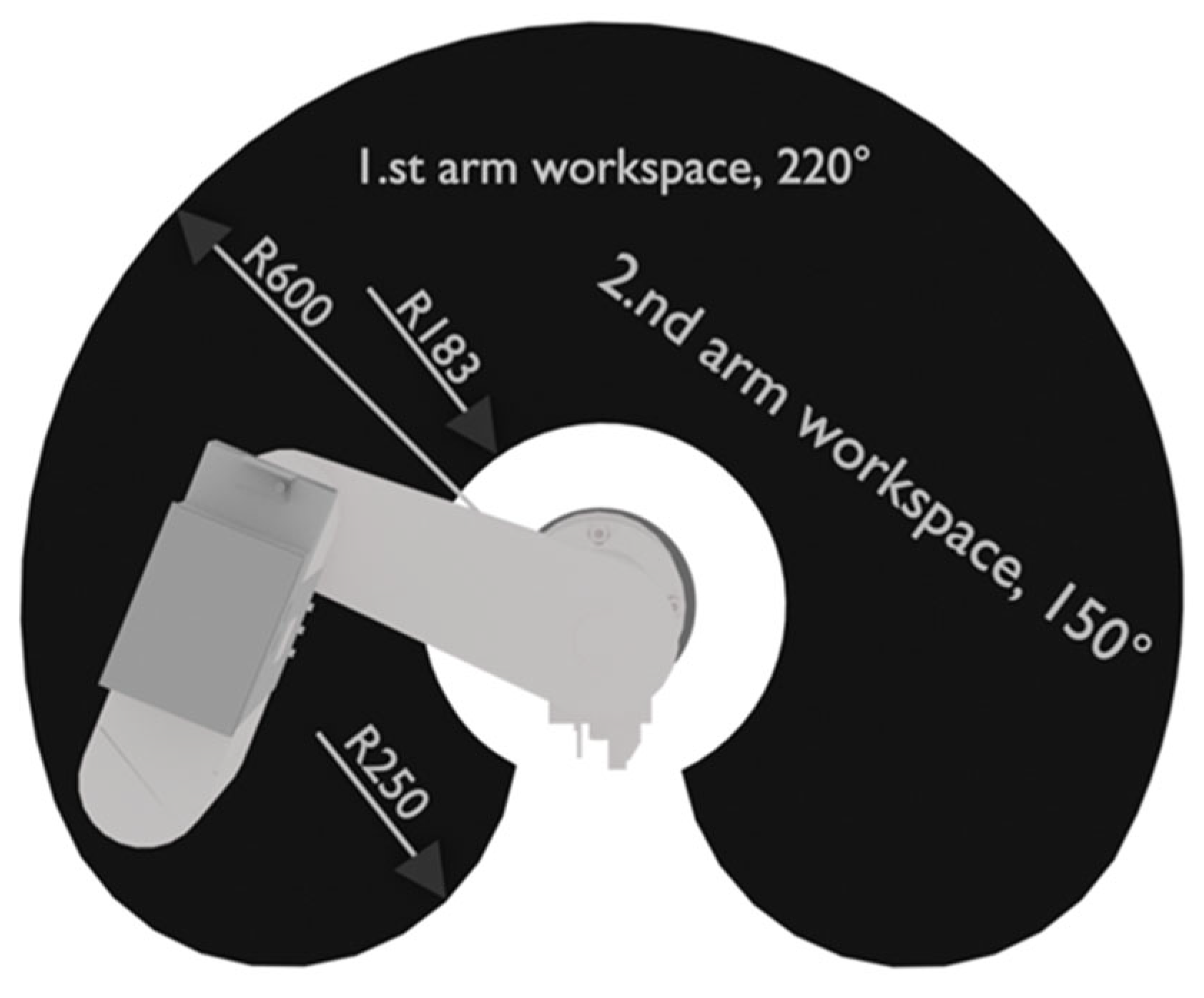
The industry standards of the time were significantly different, which is why the robot controller cannot communicate over a network and lacks USB (Universal Serial Bus) ports. The machine is of the RRT type, with an arm weighing 35 kg. For pick’n place tasks, it has an ideal payload of 2 kg (see Figure 2 and Table 1). The robot unit itself is equipped with a two-finger electro-pneumatic gripper, which requires an operating pressure of 4 bar. Maintaining the specified air pressure is necessary for stable material handling.
The robot also features a PARO QE 01 31-6000 (Subingen, Switzerland) conveyor belt system, positioned around the robot arm to ensure a proper flow of parts for sorting or placement [26]. Due to the limitations of the robot unit, as just detailed, the adaptive capability of SRX-611 has been greatly degraded. This means that it could be integrated into production lines with significant constraints, as it does not comply with Industry 4.0 standards, on which Industry 5.0 will largely rely.
Table 1. The parameters of Sony SCARA SRX-611 unit [27].
Arm LengthWorkspaceMaximum SpeedRepeatability
1. Axis350 mm1. Axis220°----
2. Axis250 mm2. Axis±150°----
--Z. Axis150 mmZ axis770 mm/secZ axis±0.02 mm
--R. Axis±360°R axis1150/secR axis±0.03 mm
The desired end point position is obtained by transforming the objects’ positions and orientations from the camera coordinate system to the robot base coordinate system. Using this end point position, actuator commands are determined via classical inverse kinematics (IK). For a SCARA-type manipulator, the IK can be expressed analytically: the two rotary arms define the shoulder and elbow angles in the plane according to the target position, while the vertical prismatic axis and end-effector joint angle are calculated from the target vertical coordinate and orientation.
Let L 1 and L 2 denote the lengths of the two planar SCARA links. The target pose of the end-effector in the base frame is given by the coordinates ( x , y , z , ϕ ) where ( x , y ) describes the planar position, z the vertical displacement, and ϕ the orientation around the vertical axis. The joint configuration is denoted as q = [ Θ 1 , Θ 2 , q 3 , Θ 4 ] .
The inverse kinematics is derived as follows. First, the squared radial distance is computed as r 2 =   x 2 + y 2 . From this, the cosine of the elbow angle c is obtained:
c = r 2 L 1 2 L 2 2 2 · L 1 · L 2
The second joint angle is then given by
Θ 2 = a t a n 2 ( ± 1 c 2 , c )
where the sign corresponds to the elbow-up or elbow-down configuration. The first joint angle is computed as
Θ 1 = a t a n 2 ( y , x ) a t a n 2 ( L 2 s i n Θ 2 , L 1 + L 2 c o s Θ 2 )
The vertical displacement is obtained as q 3 = z z 0 , while the orientation of the end-effector is adjusted by Θ 4 = ϕ ( Θ 1 + Θ 2 ) .

4. Problem Foundation

This section provides formal descriptions and designations related to the developed method, which served as the basis for designing the multi-level architecture that implements component assignment.

4.1. The Spatial Workspace of Robot Arm

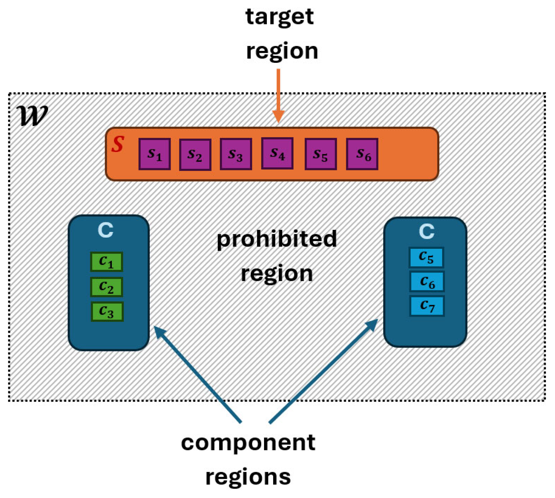
Let W R 2 denote a two-dimensional spatial workspace representing the robot device. Furthermore, this workspace can be divided into three distinct regions, each performing a different function within the application.
The first one, R b g W , is called the background region and serves as a prohibited zone. Within this one, no components can be placed, and the robot arm cannot be moved in either the start or end position.
The second one, R c o m p s W , represents the components region and contains valid placement ranges for parts expressed by:
R c o m p s = i = 1 K r c o m p   ( i ) with   r c o m p   ( i ) r c o m p   j =   f o r   i j .
That is, each r c o m p ( i ) W   ( i = 1 , , K ) is a disjoint set used to hold a specific type of current part.
The third region R s l o t s W denotes the predefined slots regions of PCB, and can be given as follows:
R s l o t s = j = 1 L r s l o t   ( j ) with   r s l o t   ( j )   r s l o t   ( i ) =   f o r   i j ,
That is, each r s l o t ( j ) W   ( j = 1 , , L ) is a disjoint set representing the target position of each implant placement.
Using the above notation, the three subregions together cover the entire workspace W R 2 :
W =   R b g     R c o m p s     R s l o t s  
while they are pairwise disjunct:
R b g     R c o m p s = ,
R b g     R s l o t s = ,
R c o m p s     R s l o t s = ,
Moreover, these regions will now define the formal background for the component–slot assignment task.

4.2. The Components-Slot Assignment

Let us consider two specific finite subsets within the workspace W R 2 . The first one C = { c 1 , c 2 , , c K } denotes a subset of detected components, and the second one S = s 1 , s 2 , , s L contains the placeholders of target slots. For the simplest scenario, let us assume that K = L , so that each component is assigned exactly one location.
Using the above notations, the following bijective mapping f : C S , and can be given as the following binary matrix:
Y 0, 1 K × L ,             Y i j = 1       i f   c i   i s   a s s i g n e d   t o   s j , 0       o t h e r w i s e                                              
The above Equation (10) clearly sets out the conditions for component–slot pairing (see Figure 3). In later sections, we designed our neural model based on this theoretical basis, which enables the prediction of assignments.

5. The Proposed Method

In this section, we present details of our proposed approach, including the architectural structure, main subcomponents and neural networks, training details, and the necessary datasets and their characteristics.

5.1. The Concept of the Method

Section 4 described and defined the problem in detail. Based on the theoretical background, it is clear that the problem cannot be solved easily or at all in a single step, and that a multi-level architecture will need to be developed.
Firstly, a basic component will be needed that is capable of recognizing objects and items found in the robot arm’s environment, enabling the robot arm to orient itself.
Next, a main component is needed that is capable of performing component slot assignment. To ensure this, the component must be able to learn the types of regions found in the robot arm’s environment, including their locations and sizes, as well as the subtypes and numbers of components found within them.
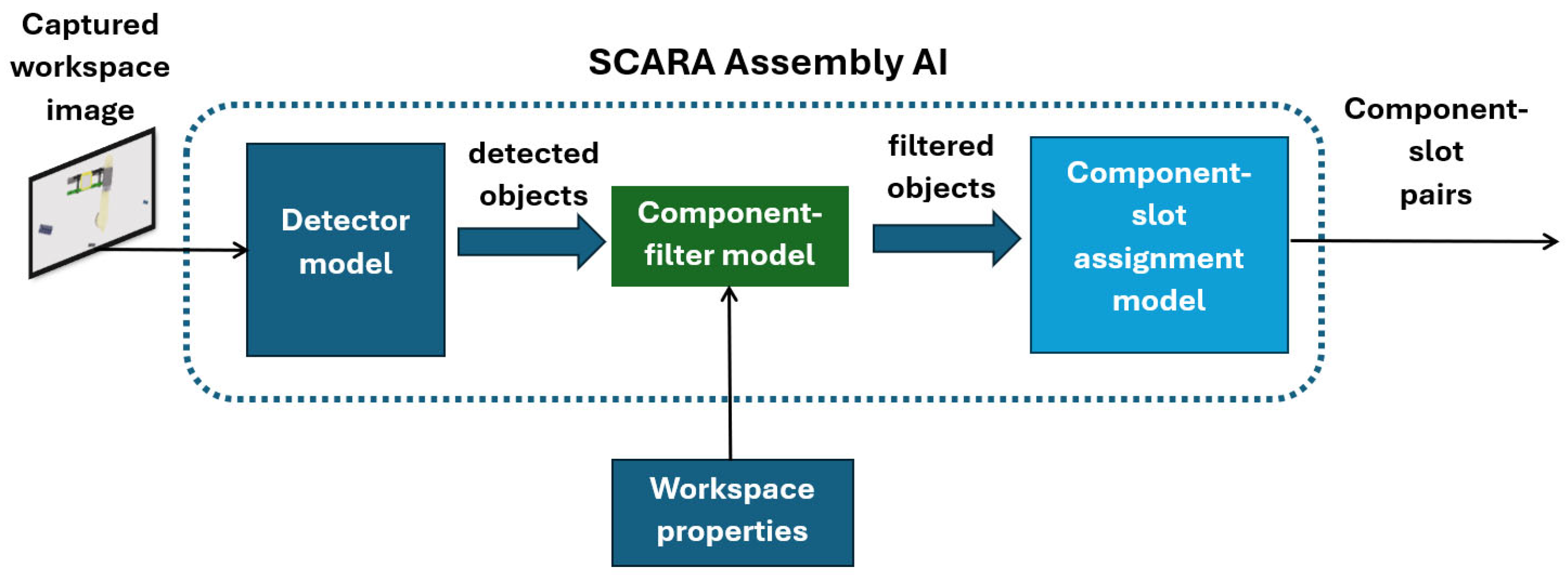
Figure 4 shows the structure of the multi-level approach we have proposed and developed.
Object recognition in the environment will utilize a real-time object detector (see Details of detector model). Component–slot assignment will employ a dedicated Set transformer-based neural network (see assignment module subsection).
Since duplicate or false detections may occur with object detectors, a filter component will be necessary to sort the output of the object detectors and retain only the correct data. This component is necessary because any kind of false detection will appear as noise and may interfere with the operation of the assignment network. Further details on the structure of the filter network are provided in the Details of Component Filter Model subsection.

5.2. Synthetic Data Generation

This subsection presents the process of generating synthetically produced datasets for architecture training, as well as the details of the modules implemented on the Omniverse platform required for this purpose.
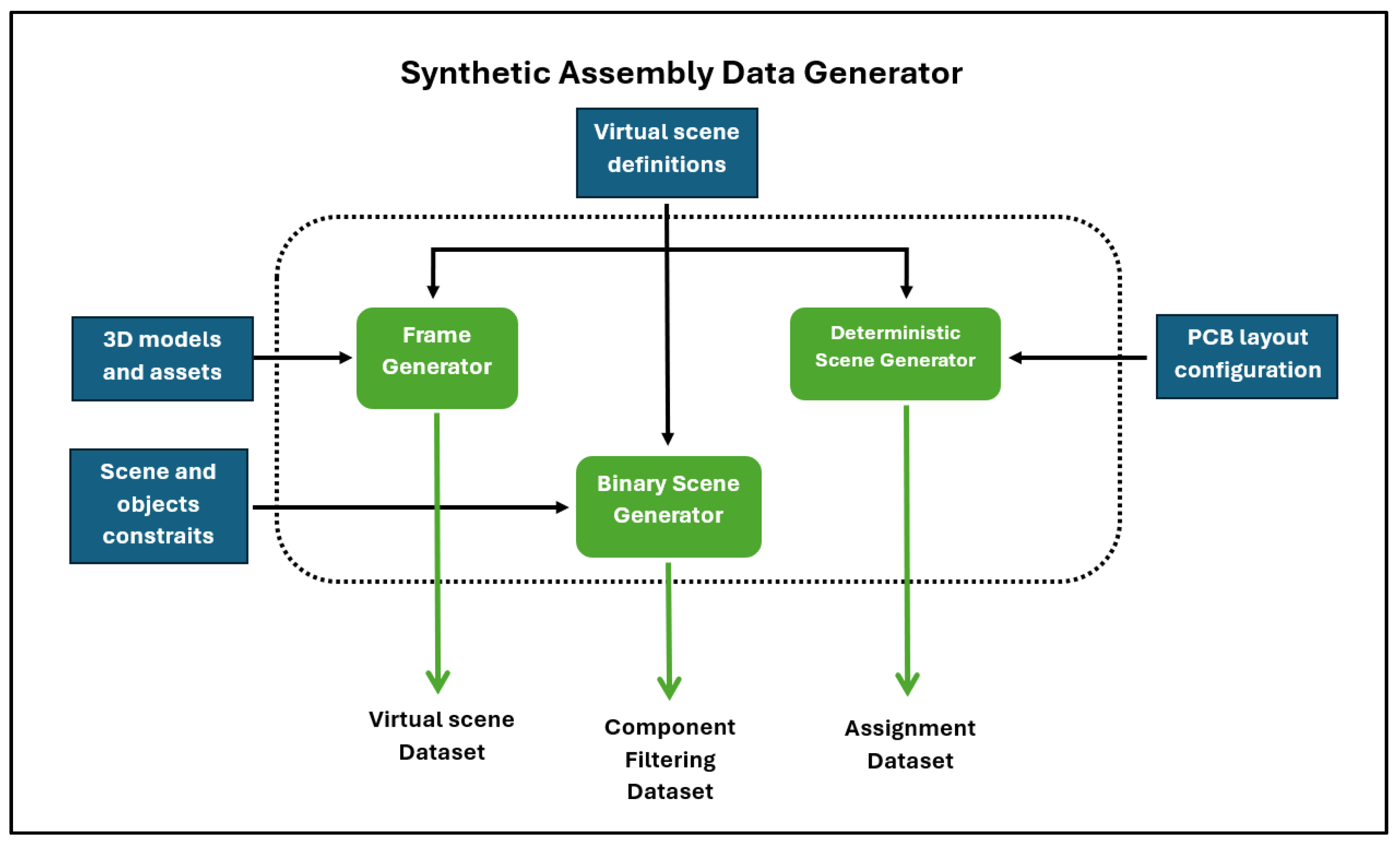
Figure 5 illustrates the primary steps of the synthetic data generation pipeline, which includes several generators.
The first step is to define the virtual scene, which includes the robot arm environment and its associated domains and characteristics. All three generators will receive these. Next, the individual datasets required for training the three main models are generated.
The Frame Generator (FG) will provide image scenes for the detector. For this purpose, it will also receive 3D models of the components found in the scene as additional input. During generation, it randomly places these elements according to the defined environment and camera settings, and synthetically produces the necessary amount of image data, along with annotations, for training the detector.
Formally, let the physical workspace be denoted by W R 2 (as introduced in Section 4.1). We now define its virtual counterpart as a synthetic scene W v i r t u a l = R , O , where R denotes the set of predefined regions within W R 2 , and O = { o 1 , , o N } is the set of instantiated 3D objects associated with their models and transformations.
Based on the above notations, a rendering function maps the synthetic scene and camera–lighting parameters Θ to a set of RGB images I t with corresponding annotations A t = ( b t , l t , m t ) where b t are the bounding boxes, l t are the class labels, and m t are the instance masks generate by:
R e n d e r : W v i r t u a l × Θ { I t , A t } t = 1 T .          
The resulting dataset serves as the virtual analog of the workspace W R 2 :
D s c e n e s = { I t , A t } t = 1 T ,       A t = ( b t , l t , m t ) .          
The task of the Binary Scene Generator (BSG) is to produce the training dataset required for the filter network to function. To this end, it will receive additional input in the form of object and region restrictions that precisely define the rules describing which cases may occur in reality and which are prohibited. In addition, the generator also produces data that can be used to filter out false results given by the detector.
Formally, let the component types be given by C = { c 1 , c 2 , , c K } where each c k is associated with physical dimensions w k , h k . For every component type c k a set of admissible placement regions R c k = { r k , 1 , r k , 2 , , r k , m k } is predefined, with r k , j W denoting an axis-aligned bounding region inside the workspace W R 2 .
A sample x i generated by the BSG is represented as a multimodal feature vector:
x i = x , y , w , h , p , q , d s , ρ , l a b e l i d , I o U m a x , v i R 10 + d v ,          
where x , y   denote the component centroid coordinates, ( w , h ) represent its physical dimensions,   p is the rotation angle, q the aspect ratio, d s the normalized Euclidean distance to the nearest slot, and ρ the estimated local density derived from the rendered 3D model.
The normalized identifier l a b e l i d encodes the component or slot category, ensuring consistency across scenes. Finally, I o U m a x is the maximum overlap with any other placed object and v i R d v is the visual embedding extracted from the shared CNN encoder.
A binary label is assigned to each sample x i as y i = 1 if the object is valid (within its designated region, tolerance, and I o U m a x , otherwise y i = 0 if the object violates these rules and is considered a dummy.
The output of the generator is thus a dataset which is used to train the binary filtering network:
D b i n = { x i , y i } i = 1 N .          
The third generator, called the Deterministic Scene Generator (DSG), will be responsible for generating the dataset required for matching components and slots.
Although the layout generator follows rule-based spatial constraints to ensure physically valid placements, the component positions, orientations, dummy ratios, and lighting conditions are randomized for each scene. Thus, the overall process remains stochastic and diverse while preserving geometric feasibility, preventing unrealistic overlaps or collisions.
Based on the previously defined virtual scene W v i r t u a l we introduce the assignment-specific structure H = P , S , M , where P = { p 1 , , p N p } is the set of valid parts, S = { s 1 , , s N s } is the set of predefined slots, and M { 1 , , N p } × { 1 , , N s } is the ground-truth assignment relation between parts and slots.
Each component p i and slot s j are represented by geometric–categorical feature vectors:
p i g e o m = x , y , w , h , c , r , q , d s , ρ R 9 ,          
s j g e o m = x , y , w , h , c , r , q , d s , ρ R 9 .
Here, x , y denote the centroid coordinates, ( w , h ) the dimensions, p the rotation angle, q the aspect ratio, d s   the normalized Euclidean distance to the nearest counterpart, and ρ the estimated local density derived from the rendered 3D mesh.
Visual information is extracted from both component and slot images by a shared CNN encoder:
p i v i s = f C N N I p i ,           p i v i s R d v ,          
s j v i s = f C N N I s j ,       s j v i s R d v ,
where f C N N · denotes the shared convolutional encoder that produces a d v -dimensional embedding.
Finally, each sample used in the assignment dataset is formed by concatenating the geometric and visual features of both entities:
x i j = p i g e o m , s j g e o m , p i v i s , s j v i s     R 18 + 2 d v .      
This multimodal feature vector serves as the input for the assignment network, allowing it to jointly exploit spatial, categorical, and visual relationships between components and target slots.
Since dummy objects have already been filtered out, every part is assigned exactly to one slot:
p i P ! s j S   f o r   e a c h   i , j M .      
where P denotes the set of components, S the set of available slots, and M the resulting one-to-one assignment mapping.
Formally, the assignment dataset is defined as
D asg = { X b , Y b } b = 1 B ,      
where each sample consists of X b = P b , S b and Y b = M b .
Here,
P b = { p i b } i = 1 N p ,         S b = { s j b } j = 1 N s
are the sets of parts and slots, with feature vectors p i b , s j b R 5 , and M b { 1 , , N p } × { 1 , , N s } denotes the ground-truth assignment pairs.
The synthetic data generator, built on the NVIDIA Omniverse Replicator framework, enables scalable photorealistic image synthesis, rendering, and detailed object annotation for robotics datasets.
Omniverse was selected for its accurate rendering, USD scene representation, and programmable data-driven API—properties vital for realistic and scalable robotic assembly datasets.
Replicator provided basic 2D annotations, while all advanced dataset logic—such as rule-based scene composition, component–slot placement, dummy generation, IOU-based validation, and JSON export—was custom-developed in Python (Version 3.10) to meet the requirements of robotic manipulation workflows.
These modules also ensure dataset consistency and facilitate integration with the PyTorch Lightning (Version 2.5.5) Datamodule during training [28].
A post-processing step using Albumentations (Version 2.0.8) introduced photometric and compression artifacts, enhancing realism beyond the rendering engine’s output [29].
Thus, Omniverse functions solely as a visual backbone. Data generation, layout control, and augmentation remain independent and reproducible, with a modular interface that supports alternative rendering backends without requiring changes to the dataset or training logic.

5.3. Details of Detector Model

When selecting the appropriate architecture for the detector component, several important factors needed to be considered. One of the most important aspects is accuracy, as the algorithm must be able to reliably distinguish between small, similar-looking components (e.g., relays, microcontrollers). It is also particularly important to detect densely spaced components, where overlap is very common. Ensuring real-time operation is also critical, as the movement of assembly robots can only be controlled if detection occurs in real time. minimizing latency is also necessary for closed-loop control and safe operation. The component must also be robust, as the parts may be very close to each other during industrial assembly. Additionally the model must be able to account for the global context to avoid incorrect assignments.
In addition, instance segmentation plays a critical role, as precise pixel-level separation of adjacent components and slot regions provides essential visual information for the assignment stage, enabling accurate mask-based localization and reducing overlaps during placement.
Over the past few decades, detector architectures have undergone significant development, and the methods developed can be divided into three main generations.
The first was the architecture of two-phase detectors, which is considered a classic approach. During their operation, proposals are first made and then undergo fine classification and regression. Typically, these include R-CNN, Fast R-CNN, Faster R-CNN, and Mask R-CNN-based methods [30,31,32,33]. They are characterized by high accuracy, but due to their slower detection time, they are more resource-intensive and often not optimal for real-time industrial applications.
The second main category consists of one-stage detectors, which generate bounding boxes and classes directly from the feature map, enabling them to operate much faster. Typical examples include the YOLO family, SSD (Single Shot Detector), and RetinaNet-based solutions [34,35,36]. Their advantages include real-time operation, but they often require post-processing (NMS) due to potential accuracy issues with dense or overlapping objects.
The third main category comprises transformer-based detectors that have emerged in recent years [37]. Unlike traditional CNN-based methods, Transformer-based detectors utilize a self-attention mechanism that enables them to process the global context of the entire image. Furthermore, they are end-to-end trainable, which means that bounding boxes and class labels are derived directly from the model, eliminating the need for separate post-processing (e.g., NMS). Typical examples include the DETR, Deformable DETR, DN-DETR, and RT-DETR architectures [19,20,38,39,40,41].
Based on the above criteria and expectations, the orientation in the robot arm’s environment will be provided by a detector based on the YOLO instance segmentation architecture [42], which will be the first main component of the proposed method.

5.4. Details of Component Filter Model

The task of the filter network component is to reliably distinguish between correct and incorrect object data among the detected components. This is necessary because there are many cases that can cause problems or do not comply with manufacturing rules. These include, for example, objects being placed in the wrong location, extending beyond the permitted regions, or colliding with other components. If these incorrect occurrences were to remain unchanged in further processing, they would reduce the performance and reliability of the slot assignment module, as it would have to learn combinations that cannot occur in the actual manufacturing process, and it would be difficult to find the correct pairings when placing component slots.
We had to consider several factors when designing the filter component. These include defining validity criteria, properly defining dummy components, and describing possible false detections.
In the case of the first criterion, it is important that a component can be considered valid if it is located in the region assigned to its type, the region may not exceed the percentage value defined in the scene, and its overlap with other components, measured by I o U , does not exceed the specified threshold value.
In the second case, any object that violates any of the design criteria or scene constraints is classified as a dummy category. These must be automatically separated from valid components by the network.
In the third case, the key point is to determine, based on knowledge of the selected detector architecture, the possible output data that could cause problems during component–slot pairing. This prepares the filter component to filter out this erroneous data and identify it as dummy data.
In the fourth case, the filter network can visually identify defective, damaged, or misplaced components. By incorporating visual embeddings from the shared CNN encoder, the model can reject items that are visually inconsistent with the expected component type or slot region, even if their geometric features appear similar. This enables the system to filter out incorrect, missing, or visually corrupted components before the assignment stage, while the weighted binary cross-entropy loss (13) ensures balanced learning between valid and dummy samples.
Based on Equation (13), each object can be described by a multimodal feature vector. The purpose of the network is to make a binary decision: for each sample, it clearly indicates whether the given component is valid ( y i = 1 ) or dummy ( y i = 0 ) . This will exclude faulty objects from further processing, and the assignment module will only learn from real part–slot pairings.
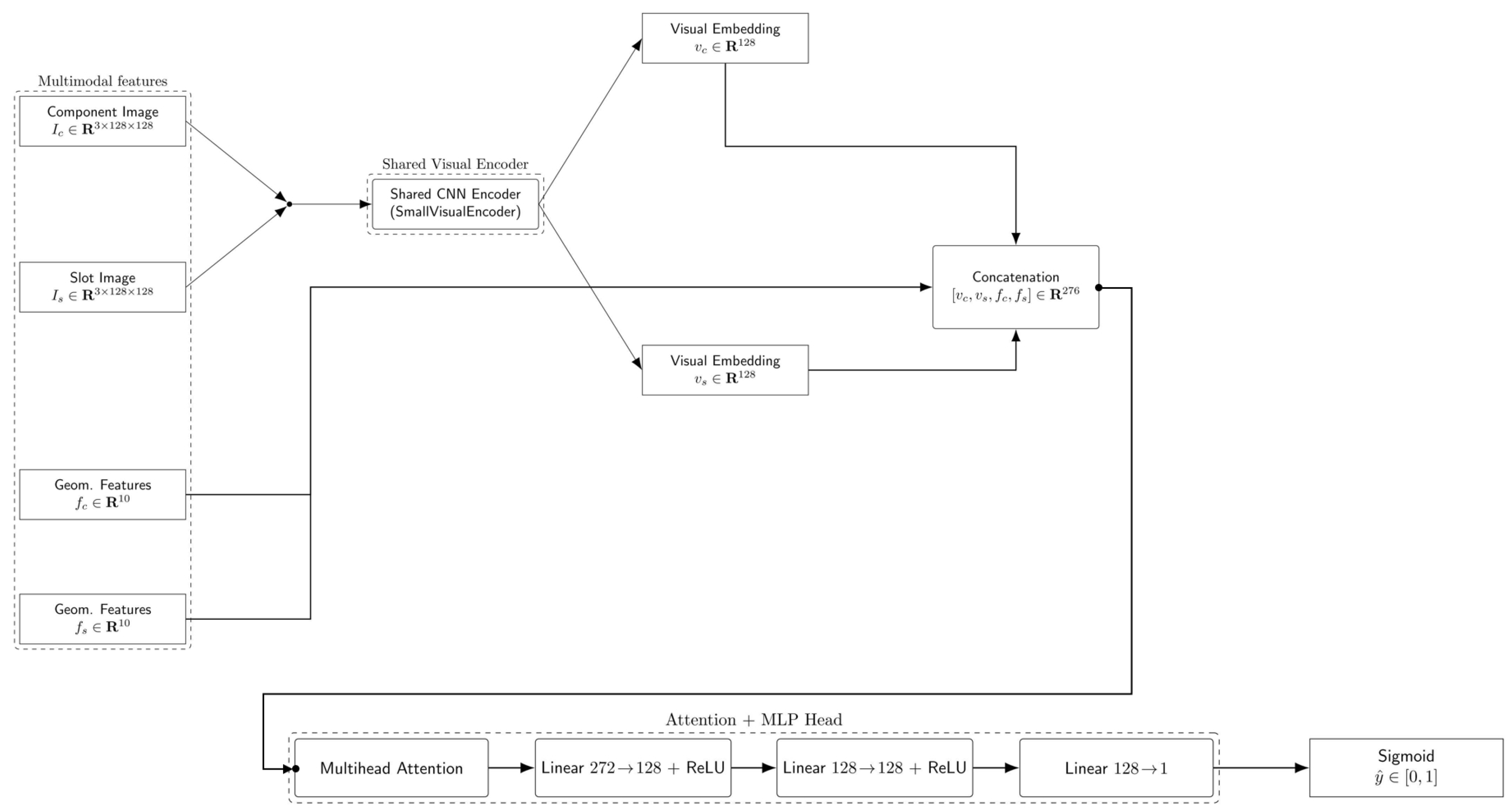
Considering the above criteria, we developed a self-attention-based multi-layer perception architecture. The structure of which is illustrated in Figure 6.
The input to the filter network is a multimodal feature vector for each component, combining both geometric attributes (position, size, type, and overlap measure) and visual embeddings extracted from a shared CNN encoder. These multimodal representations are first processed by a multi-head attention block, which captures relationships between components by jointly reasoning over visual and geometric cues. The attention-enhanced features are then passed to a multilayer perceptron (MLP) head with two hidden layers, producing a single scalar logit value. Finally, a sigmoid activation converts the logit into a probability that determines whether the given component belongs to the valid or dummy category.
The attention block enables the model to capture contextual dependencies between the multimodal feature dimensions before the final classification.
While the MLP layers alone perform independent nonlinear transformations, the multi-head attention mechanism allows the network to dynamically reweight and correlate visual and geometric cues, emphasizing the most informative components.
If the attention module is removed, the model loses this adaptive feature interaction, leading to poorer generalization, especially when visually similar or spatially overlapping components appear in the input.
Although dummy labels are generated according to rule-based scene constraints, the filter network itself is fully data-driven and learns to recognize invalid components from visual–geometric cues, enabling generalization to unseen configurations.
The cost function of filtering network is based on computing binary cross entropy over multimodal feature inputs. Formally, given the dataset D b i n and the prediction y i ^ = σ f θ x i , the loss is defined as:
L WC θ = 1 N i = 1 N w 1 y i log y i ^ + w 0 1 y i log 1 y i ^ ,
where w 1 , w 0 > 0 are class weights balancing the valid and dummy samples.

5.5. Details of Assignment Model

The assignment module will form the backbone of the assembly method architecture. For this reason, this module must be the most robust. Its main task will be to determine the appropriate component pairings based on the detected and filtered object characteristics, the pick-and-place layout, and to find the correct slot position.
The problem can be described by finding a bijective mapping between two sets, namely, finding a one-to-one mapping between the component set C and the sloth set S. These sets can have a variable number of elements, and the number of elements can vary from sample to sample. Furthermore, their order can be arbitrary. Therefore, it will be necessary to design a neural network that meets the following important criteria.
The network must be permutation invariant with respect to the input feature vectors and capable of handling a variable number of elements. Another key consideration is the global consistency of the dataset, which is essential for addressing challenges inherent to the assembly domain, such as densely arranged components, numerous visually or geometrically similar parts, and minimal intra-class variations.
To overcome these difficulties, visual embeddings extracted from the shared CNN encoder are integrated into the input representations, enabling the model to learn spatial and appearance-based relationships between components and their corresponding slots.
This multimodal design allows the attention layers to reason jointly over geometric alignment and visual similarity when predicting valid assignments.
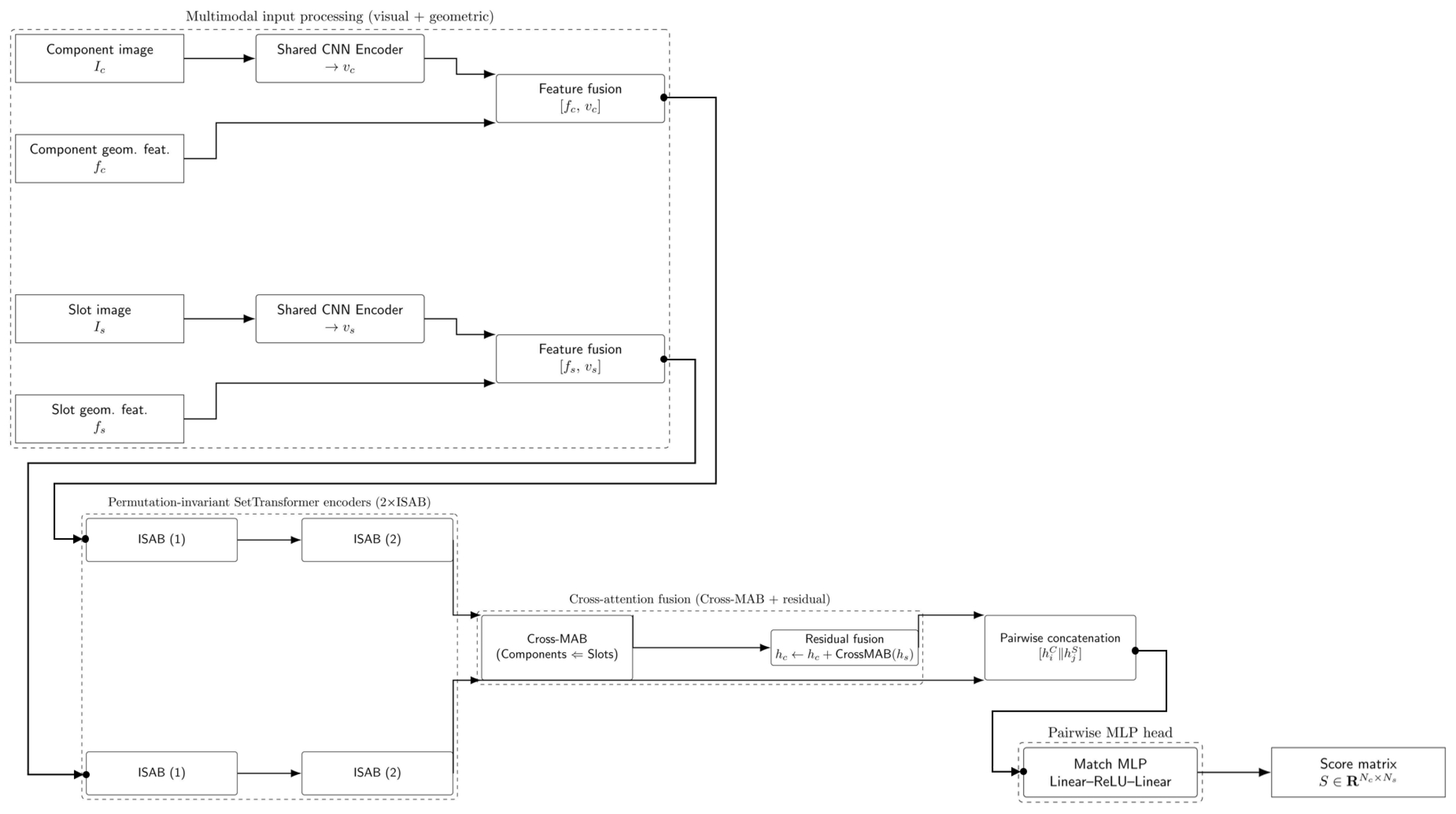
Taking the above considerations into account, we designed the assignment neural network, the structure of which is shown in Figure 7.
We applied an extended Set Transformer-based architecture to solve the slot assignment task using multimodal components and slot features.
Each input set contains both geometric descriptors (position, size, type, overlap) and visual embeddings extracted from a shared CNN encoder.
These multimodal features are concatenated into a vector p i = p i g e o m , v i R 9 + d v (see Equations (15) and (16)). The two input sets (components and slots) are processed separately by independent encoders composed of two Induced Set Attention Blocks (ISAB), ensuring permutation invariance and the ability to handle variable numbers of elements.
From the encoded representations, a pairwise feature is formed for every possible component–slot pair by concatenating the corresponding vectors.
Unlike the original Set Transformer, the proposed architecture introduces a Cross-Multihead Attention Block) between the encoded sets, allowing contextual information from slot embeddings to refine component embeddings through residual fusion.
This cross-attention mechanism enables the model to learn appearance-guided correspondences, thereby improving its ability to discrimination between visually similar or spatially overlapping parts.
The resulting embeddings are then combined pairwise and passed through a shared attention-based MLP head, producing the score matrix S R N c × N s that expresses the strength of each component–slot assignment and is optimized using the differentiable Soft Hungarian loss during training and evaluation.
In contrast to the original Set Transformer, which aggregates a single set representation via pooling, the proposed dual-encoder architecture with multimodal feature fusion and Cross-Multihead Attention Block-based interaction explicitly learns inter-set visual-geometric relations required for robust assignment prediction.
For the assignment task, we optimize the score matrix S R N c × N s produced by the model. Given the ground-truth matching M we define the soft Hungarian loss as:
L H u n g a r i a n _ b a s i c S , M = 1 M i , j M log σ s i j ,
where S = s i j R N p × N s is a score matrix, M { 1 , , N c } × { 1 , , N s } is the set of ground-truth pairs, and σ denotes the sigmoid function.
However, the basic Hungarian loss in Equation (14) does not penalize wrong pairs selected by the assignment, nor ground-truth G T pairs that are missed by the assignment.
To address this, we extend the baseline loss function and compute it on the cost S denoted by M h = H u n g a r i a n ( S ) . Let M g t be the set of GT pairs, and define three disjoint sets: A = M h   M g t (correct selections), B = M h   M g t (selected but wrong) and C = M g t   M h (missed GT pairs). We then use a binary cross entropy-based match term that rewards A and penalizes B , and a complementary miss term that penalizes C . The final objective is their weighted sum:
L m a t c h S , M h , M g t = 1 M h i , j M log σ s i j + i , j M l o g 1 σ s i j
L m i s s S , M h , M g t = 1 M g t i , j M log σ s i j
L H u n g a r i a n _ a s s e m b l y = L m a t c h S , M h , M g t + α L m i s s S , M h , M g t ,   α 0  
The choice of the Soft Hungarian formulation over alternatives such as Sinkhorn distances or attention-based matching is primarily motivated by task-specific stability and interpretability considerations.
While Sinkhorn-based optimal transport approaches provide differentiable approximations of the assignment problem, they require explicit regularization (e.g., entropy terms) and temperature hyperparameters that are highly sensitive to scale and dataset statistics.
In preliminary experiments, these methods produced unstable gradients and occasionally degenerate assignment distributions, especially in cases with multiple visually similar components or near-duplicate slots.
In contrast, the Soft Hungarian loss maintains the combinatorial structure of the discrete Hungarian algorithm while introducing differentiability through a sigmoid-normalized score matrix.
This enables the model to learn assignments end-to-end in a stable and interpretable manner, without additional regularization or tuning of transport temperatures.
Furthermore, unlike purely attention-based matching, which only models pairwise similarity implicitly, the proposed loss explicitly enforces one-to-one consistency between components and slots, a requirement essential for robotic assembly and pick-and-place applications.
The use of the sigmoid function in Equation (14) is not ad hoc but serves to ensure the stability and interpretability of the Soft Hungarian loss.
If raw, unbounded logits were applied directly, the resulting cost matrix could exhibit extreme values, potentially leading to unstable assignment optimization and distorted gradient distributions.
In contrast, the sigmoid transformation normalizes the pairwise matching strengths to the [ 0 , 1 ] interval, allowing them to be interpreted directly as probabilistic correspondences (the likelihood that a component belongs to a specific slot).
This normalization is crucial in the differentiable formulation of the Soft Hungarian loss, where the assignment matrix must approximate the ideal binary matching in a continuous and differentiable form.
Specifically, the sigmoid scales the cost matrix to support stable convergence, remains consistent with the binary cross-entropy component used in the extended loss formulations (see Equations (15)–(17)), and preserves the expressiveness of the logit-based MLP head while aligning the output domain with a probabilistic interpretation.
Furthermore, the soft Hungarian formulation itself is not heuristic, but rather a differentiable approximation of the discrete assignment function, as adopted in several prior works [7,19,43].
The objective is to allow the network to learn the optimal matching end-to-end, without relying on the non-differentiable classical Hungarian algorithm during training.

6. Training and Validation of the Models

This subsection contains details on the training and validation of architecture models. All models, including the associated software modules and dataset management routines, were implemented in PyTorch Lightning [3]. Virtual layout test scenes were also assembled within NVIDIA Omniverse [2] for training the object detector. The associated descriptions and parameters were stored in a JSON data structure.

6.1. Datasets

For evaluation and training, we used the T-LESS V2 dataset [44], a publicly available benchmark widely applied in industrial object recognition and pose estimation tasks.
T-LESS contains both real RGB-D captures and the corresponding 3D CAD models of texture-less industrial parts, making it particularly suitable for validating model performance under realistic manufacturing conditions.
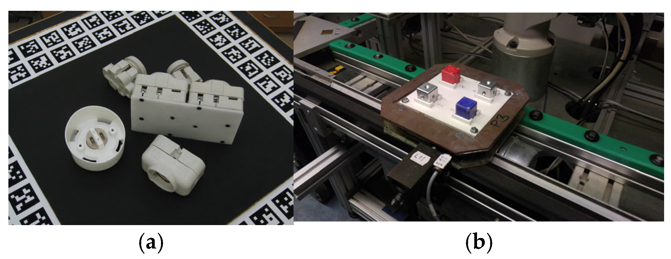
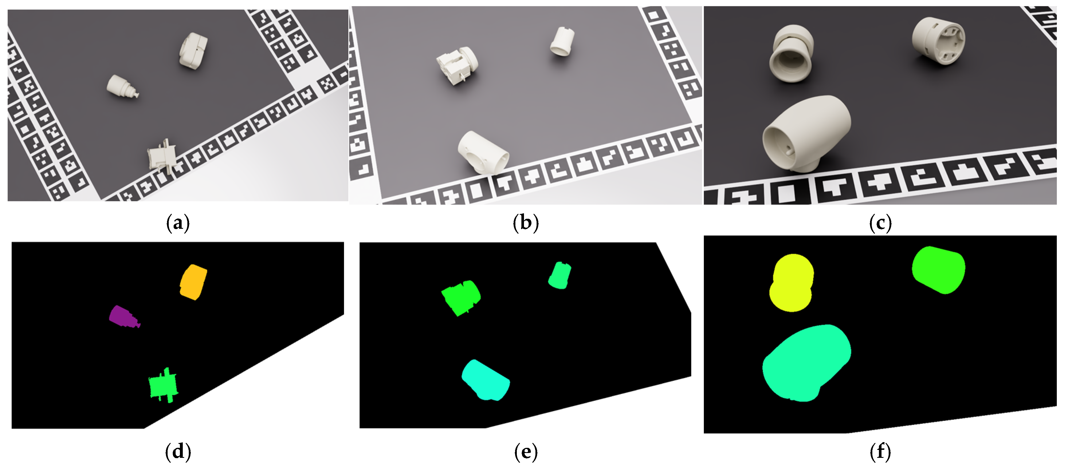
Compared to other public datasets such as LineMOD or HOPE [45,46], T-LESS provides a higher number of visually similar, texture-less components, which closely match the challenges of industrial pick-and-place and assembly scenarios (see Figure 8a).
From the complete dataset, we selected 28 representative object models covering a diverse range of shapes, sizes, and visual similarities.
Since T-LESS does not include slot geometries, synthetic slot regions were procedurally generated during layout creation to enable component–slot pairing for assignment training. In these layouts, the instance masks encode not only the segmentation boundaries but also the spatial correspondence between each component and its matching slot, allowing the model to learn pairing relationships directly from visual supervision.
To further adapt the dataset to our robotic assembly domain, four additional 3D models with corresponding slot counterparts were created in-house, resulting in a combined set of 32 object classes, including both public component models and proprietary component–slot pairs designed for domain-specific evaluation. Because our detector architecture is segmentation-based, instance masks were manually refined for each object class to ensure precise supervision of the segmentation outputs during training.
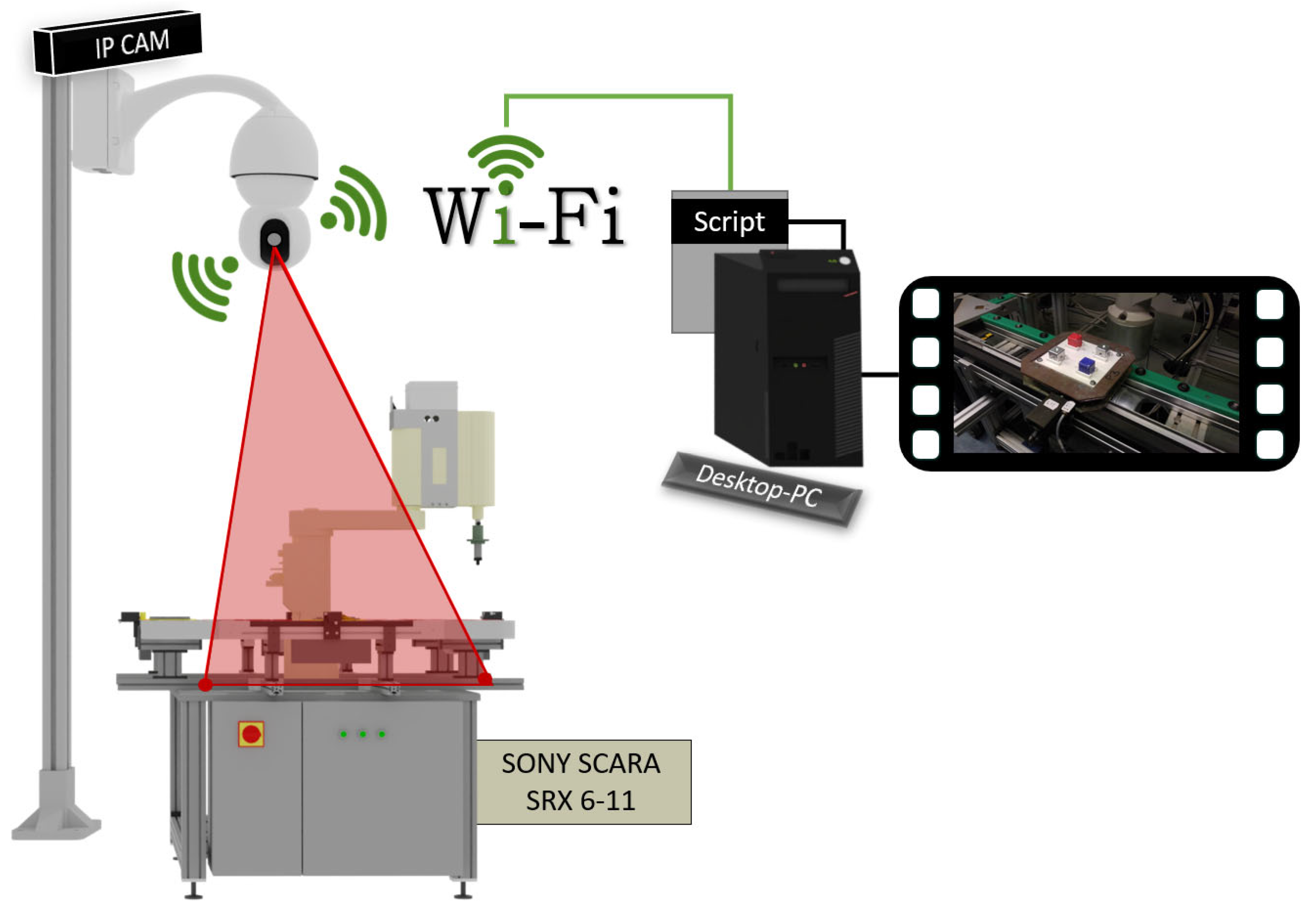
In addition, approximately 300 real RGB images were captured for two proprietary models using a TP-Link Tapo C200 PTZ IP camera (1920 × 1080 px, 1/2.9″ CMOS, f = 3.83 mm, F = 2.4, Shenzhen, China, see Figure 8b).
These real samples were used not for initial training but for photometric calibration and domain fine-tuning, improving robustness under real illumination and sensor noise conditions while validating the sim-to-real consistency of the perception pipeline.
This hybrid dataset design allowed the model to jointly learn visual component–slot correspondences from instance-level masks and geometric assembly relationships under both synthetic and real-world conditions.

6.2. The Detector Model

To obtain a large and well-controlled training set for the detector, we generated synthetic images using NVIDIA Omniverse Replicator [3]. The rendering pipeline was designed to closely mimic our pick-and-place setup and the characteristics of the T-LESS dataset, thereby reducing the synthetic-to-real domain gap.
Scene layouts were defined via JSON configuration files, specifying, for each subscene, the active object models and their placements on a calibration board. For each configuration, the Frame Generator instantiated a 2 × 2 grid of object regions and positioned the models on this grid with small random perturbations in translation, rotation (±15°), and scale. This yields realistic variations in pose and relative spacing while preserving physically valid arrangements.
For each subscene, a virtual RGB camera was placed above the workspace and randomly jittered in position and viewing angle around the scene center. The camera intrinsics (focal length and resolution) were chosen to be consistent with the calibrated setup of our real recordings and with the T-LESS camera configuration, ensuring a comparable field of view and projection geometry between synthetic and real images.
Objects were rendered using the physically based OmniPBR VMaterials2 package, which employed neutral, slightly rough, non-metallic surfaces to simulate textureless industrial parts [47]. The supporting plane was textured with a printed calibration/marker pattern similar to the board used in the real experiments, ensuring a consistent geometric context for both domains.
To achive realistic illumination, we combined a dome light with a high-resolution HDR environment map (studio lightbox HDRI), which provides soft, global lighting, and an additional disk-type light above the workspace [48]. Light intensity, color temperature, and direction were stochastically varied per frame, producing a realistic range of indoor, laboratory-like lighting conditions. This variability enhances robustness to illumination changes and better aligns with the diversity observed in the T-LESS and real experimental setups.
We enabled ACES tone mapping (gamma 2.2) and applied mild color correction to approximate standard camera response. In addition, film grain was added at a low level to emulate sensor noise and compression artifacts, which further narrows the gap to real RGB images captured by the Tapo camera.
Replicator’s built-in annotators were used to export RGB images, tight 2D bounding boxes, and instance segmentation masks for all visible objects. The renderer was configured in path-traced mode (64 spp) to obtain stable, low-noise supervision signals (see Figure 9).
While Omniverse provides physically consistent synthetic data, additional image-space augmentations were applied using Albumentations [29] to further reduce the synthetic-to-real domain gap and better match the variability of real-world sensor data and assembly conditions (see Table 2 for details).
In the next step, the dataset module read in this synthesized dataset and generated the training, validation, and test batches required for training. To minimize the remaining synthetic-to-real domain gap, a small subset of real RGB images captured with the Tapo camera was also included in the dataset. These real samples were augmented using the same Albumentations pipeline as the synthetic data to harmonize illumination, color balance, and sensor noise characteristics across domains.
To quantitatively assess the alignment between the synthetic and real subsets, we computed standard perceptual similarity metrics.
The results confirmed that the applied randomization and augmentation pipeline effectively reduced the visual domain gap. The CLIP similarity between synthetic and real images reached an average of 0.8358, indicating strong feature-space correspondence.
The LPIPS perceptual distance was measured at 0.532, reflecting moderate perceptual similarity, while the Fréchet Inception Distance (FID) of 251.83 and Kernel Inception Distance (KID) mean of 0.188 ± 0.12 quantify the remaining statistical difference between the two domains.
Although the domain randomization considerably improved visual alignment, the relatively high FID and LPIPS values indicate that a residual gap persists between the synthetic and real data distributions. Therefore, incorporating a limited number of real images into the training process was crucial to further regularize the feature space and enhance the cross-domain generalization of the detector and assignment networks.
The configuration and parameters used during detector training are summarized in Table 3.
Table 4 summarizes the quantitative performance degradation of the four YOLO-based segmentation models evaluated under additive Gaussian noise.
Each validation subset was corrupted to yield PSNR levels of approximately 34 dB, 28 dB, and 22 dB, representing mild, moderate, and strong degradation, respectively. The results indicate that all models maintain acceptable precision above 30 dB, while detection accuracy drops sharply below 28 dB.
Among the evaluated networks, the YOLOv11 series demonstrates the highest robustness maintaining higher recall and mAP values even under severe noise conditions, whereas the lightweight nano variants exhibit faster performance degradation due to their limited feature capacity. These findings confirm that the latest generation of YOLOv11-based lightweight detectors achieves a superior balance between accuracy and resilience to sensor noise, which is essential for real-world robotic perception systems.
Additionally, the inference time of each detector model was evaluated in the same GPU environment to assess its real-time suitability.
The YOLOv8-Nano-Seg achieved an average inference time of 2.0 ± 0.2 ms per frame, while the YOLOv8-Small-Seg required 4.2 ± 0.3 ms. The newer YOLOv11-Nano-Seg exhibited similar latency at 2.3 ± 0.2 ms, and the YOLOv11-small-seg reached 4.1 ± 0.2 ms.
These results confirm that all evaluated segmentation models operate well within real-time constraints, with the YOLOv11 series providing slightly improved efficiency compared to the corresponding YOLOv8 variants.

6.3. The Component Filter Model

To train the filter model, we implemented two main components, which will be referred to as the Binary Scene Generator and Component Filter Trainer.
The Binary Scene Generator (BSG) module was responsible for constructing training, validation, and test batches by synthesizing complete assembly layouts in JSON format.
Each configuration file defines the spatial regions, component instances, and valid slot relations that may occur in a realistic industrial environment.
Additionally, the generator encodes rule-based constraints that describe invalid or prohibited states, enabling the system to automatically distinguish between physically feasible and infeasible component–slot pairs.
To provide multimodal learning capability, a visual–geometric dataset module was introduced, implemented as the VisualPickPlaceDataset and VisualPickPlaceDataModule classes. This module not only parses the JSON layouts generated by the BSG but also loads pre-rendered visual tensor (.pt files) for both components and slots.
Each sample, therefore, contains two synchronized image embeddings and two 8-dimensional numerical feature vectors, including position ( x , y ) , size ( w , h ) , rotation, aspect ratio, normalized distance to slot, and estimated density.
To improve robustness, the module generates domain-randomized dummy samples, applying controlled visual perturbations such as HSV shift, blur, cutout, and noise injection to simulate real-world imperfections.
An additional online streaming variant (LazyPickPlaceDataset) was also implemented to enable memory-efficient, on-the-fly batch creation during large-scale experiments.
Together, these components form the baseline data pipeline used throughout this work, providing unified visual and geometric inputs for both the filter and assignment networks.
The Visual Filter Network (VisualFilterNet) was trained using a systematic hyperparameter optimization procedure to ensure robustness and generalization across diverse assembly configurations.
An Optuna-based search was applied to automatically identify the most effective architectural and training parameters for the attention-based multimodal classifier [49].
The objective function maximized the validation F1-score using the VisualPickPlaceDataModule with domain-randomized visual inputs and dynamically generated dummy samples.
A total of twenty Optuna trials were executed, each exploring a distinct combination of learning rate (1 × 10⁻⁶–5 × 10⁻⁵, log scale), hidden layer dimension (32, 64, 128), CNN embedding size (16, 64, 128), number of convolutional layers (2–4), optimizer type (Adam or AdamW), and dropout probabilities (0–0.3) for both the convolutional encoder and the MLP head (see Table 5 and Table 6 for details).
Training was limited to 25 epochs per trial, with early stopping based on the validation accuracy metric, and class-imbalance weighting was applied to the binary cross-entropy loss.
The optimization produced consistently high-performing configurations, with validation accuracies ranging from 0.929 to 0.979 across the top five trials.
The best configuration, defined by a learning rate of 7.3 × 10⁻⁶, a hidden dimension of 128, an embedding dimension of 128, and the Adam optimizer, achieved the highest validation accuracy of 0.979, confirming the effectiveness of structured hyperparameter exploration.
Moderate hidden-layer sizes (64–128) provided the best balance between precision and recall, while deeper CNN variants offered negligible gains, indicating that lightweight architectures are sufficient for reliable filtering under domain-randomized and noisy visual conditions. Overall, the Optuna study demonstrated that the proposed attention-based Visual Filter Network remains robust, reproducible, and well-generalizable across a broad range of hyperparameters.
To evaluate the contribution of attention in the filtering stage, the multi-head attention block was removed from the Visual Filter Network while keeping all other settings identical. The validation accuracy dropped from 0.979 to 0.846, confirming that attention plays a critical role in distinguishing valid from dummy components under visual noise.
Without the attention mechanism, the model tends to overfit to appearance cues and fails to suppress irrelevant detections, leading to unstable validation behavior.
On the target RTX 4060 Ti GPU (Santa Clara, California), the optimized Visual Filter Network performs a single forward pass in approximately 1–2 ms, confirming that the filtering stage operates well within real-time constraints.

6.4. The Assignment Model

We have also implemented two main components for learning the assignment model, called the Deterministic Scene Generator and the Assignment Trainer.
The Deterministic Scene Generator will also be a dataset module, whose task will be to generate the component–slot value pairs required for training. The generator module is responsible for creating large-scale, diverse, and procedurally randomized training configurations that describe possible industrial layouts. It consists of two submodules: gen_global_layout.py, which defines the global workspace geometry and component–slot topology, and generate_layouts.py, which produces individual configuration files based on the global design.
The resulting JSON descriptors (global_components.json and global_layouts.json) specify all available component categories, dimensional ranges, and spatial boundaries.
Each generated configuration (config_pickplace_XX.json) contains normalized positions of components and slots, random perturbations in translation and rotation, and derived geometric attributes such as aspect ratio, density, and normalized distance to the corresponding slot.
This setup guarantees that each training and validation sample originates from a unique procedural layout, while the overall spatial distribution remains consistent across all splits.
By varying random seeds and jitter ranges, the generator can also produce unseen arrangements and component categories, supporting cross-layout and cross-category generalization testing.
In addition to the geometric configuration, each component–slot pair is associated with cropped visual patches extracted from the rendered scene rather than the full image.
This ensures that the model receives object-level visual information, focusing on the relevant component and slot regions, while excluding global background variations from the learning process.
A comprehensive experimental protocol was established to evaluate the proposed visual–geometric assignment model under multiple controlled conditions, as summarized in Table 7.
The experiments were divided into five categories. The α-sensitivity analysis examined how the weighting factor in the Soft Hungarian Loss influences convergence and stability. The model-variant comparison explored the effect of hidden dimensions, attention heads, and induced points on representational capacity and overall accuracy. To verify robustness and real-world applicability, a generalization test was performed on previously unseen industrial layouts, new component categories, and partial or rotated views, generated through the global layout pipeline.
Finally, a failure-case analysis qualitatively examined typical mismatches, highlighting the model’s limitations on geometrically similar or visually overlapping parts. All experiments were executed under consistent hardware and data conditions, using identical evaluation metrics (accuracy, precision, recall, and F1-score) to ensure reproducibility and fair comparison across configurations.
The Assignment Trainer module was implemented as a reproducible PyTorch Lightning pipeline to train the visual–geometric assignment network under controlled experimental conditions.
Training utilized the AssignmentFineTuneDataModule, which loaded pre-generated configuration files from the global layout generator and divided them into 80%, 10% and 10% train, validation, and test splits.
Each batch contained synchronized component–slot image pairs and their corresponding 9-dimensional feature vectors.
Table 8 compares the proposed assignment model with two baseline approaches that rely on classical matching strategies.
The deterministic Rule-based Hungarian method, relying solely on geometric cost metrics (IoU and centroid distance), achieves an F1-score of only 0.041, indicating very limited robustness under domain-randomized conditions.
The combined Hungarian and attention baseline, representing a non-learned visual-feature-weighted matching, yields a moderate improvement with an F1-score of 0.781, reflecting better alignment but still lacking end-to-end optimization capability.
In contrast, the proposed Set Transformer and Soft Hungarian Loss framework consistently achieves an F1-score of 0.942, with a precision of 0.966 and a recall of 0.914, marking a substantial performance gain over both deterministic and attention-based baselines.
This confirms that a fully differentiable matching formulation combined with permutation-invariant attention significantly enhances both accuracy and training stability.
A similar ablation was performed for the assignment module by disabling the attention layers within the Set Transformer. In this case, the F1-score dropped from 0.942 to 0.781, demonstrating that attention is essential for learning relational dependencies between component and slot embeddings. The absence of attention significantly reduces the model’s ability to reason over spatial–visual correspondences, resulting in mismatched pairs and slower convergence.
Table 9 summarizes the results of the α-parameter sensitivity experiments for the proposed Soft Hungarian Loss.
The analysis reveals that the non-differentiable baseline configuration (α = 0.0, corresponding to the Hungarian plus Attention variant) achieves an average F1-score of 0.763, albeit with slower convergence (approximately 18 epochs) and the highest validation loss (0.442), indicating limited stability and generalization.
Introducing a moderate weighting (α = 0.25) yields a substantial improvement, increasing the F1-score to 0.899 while reducing the validation loss to 0.342.
The best overall trade-off between precision and recall is obtained for α ≈ 1.0, where the model reaches its peak F1-score of 0.955 with fast and consistent convergence around 15 epochs.
Further increasing α beyond 1.5 produces only marginal changes, suggesting that the Soft Hungarian Loss remains stable and insensitive within the [0.5–2.0] range.
These results demonstrate that the differentiable matching formulation stabilizes training, reduces variability across runs, and consistently outperforms the hard Hungarian baseline in both accuracy and robustness.
Table 10 presents the architectural ablation study, where the hidden dimension, embedding size, number of attention heads, and induced points were systematically varied to evaluate the model’s representational capacity.
The lightweight configuration (V1) converges quickly but exhibits moderate underfitting on complex layouts, achieving an average validation F1 score of 0.854 ± 0.126 with minimal memory usage (≈14.7 MB).
The extended configuration (V3) achieves the highest accuracy (0.941 ± 0.22 F1-score) but requires substantially more parameters (≈14.2 M) and memory (≈56.8 MB).
The balanced variant (V2, 384 hidden units, 16 heads, 64 induced points) offers the best compromise between performance and efficiency, reaching 0.878 ± 0.4 F1 while maintaining a low inference time of 3.67 ms.
Overall, the results confirm that the proposed architecture scales gracefully with model capacity and remains stable across a broad range of configurations.
Table 11 presents the generalization experiments of the Visual Assignment Network under three unseen test conditions.
When evaluated on unseen layouts with new industrial topologies but the same component set, the model achieves an F1-score of 0.764, showing only a moderate drop due to spatial rearrangement.
For unseen component categories excluded during training, the network maintains a high precision (0.966) and an overall F1 score of 0.898, confirming the partial transferability of learned geometric–visual relationships.
Under rotated or partially occluded views (10–15° rotation and 20% occlusion), the model remains robust with an F1-score of 0.878, indicating resilience to viewpoint and visibility distortions.
Overall, the results demonstrate that the proposed network generalizes reliably across spatial, categorical, and visual variations, validating its robustness for unseen real-world industrial scenarios, including partial occlusions, component contact, and minor positional misalignments.
Table 12 summarizes the most frequent failure modes observed during validation and generalization testing.
The majority of errors occur in visually ambiguous situations, such as those involving nearly identical components or partial occlusions.
Rotational symmetry and dense spatial clustering can also lead to incorrect slot assignments, especially when multiple candidate regions share similar visual embeddings.
Importantly, no instability-related or random assignment errors were observed, confirming that the network’s failures are deterministic and largely attributable to dataset-level ambiguities rather than model inconsistency.
This qualitative analysis provides a transparent overview of the model’s current limitations and highlights directions for future dataset augmentation and texture-randomization improvements.
The results presented above comprehensively evaluate the proposed visual–geometric assignment model across architectural, optimization, and generalization aspects.
Both the quantitative analyses (Table 8, Table 9, Table 10 and Table 11) and the qualitative inspection (Table 12) confirm that the model achieves stable, high-accuracy performance and maintains consistent behavior under a wide variety of synthetic test conditions.
To further verify its applicability to real-world scenarios, the next section presents a simulation-based and physical validation study, where the trained models are integrated into the SCARA assembly environment to assess inference speed, real-time feasibility, and robustness under realistic sensor noise and lighting variations.

7. Simulation in NVIDIA Omniverse Platform and Real-World Validation

One of the most critical stages in the proposed workflow is the validation of the trained models, both in virtual and physical environments.
To ensure a smooth transition from synthetic data generation to real deployment, the following section presents a two-level validation process.
First, the visual–geometric assignment network was integrated into a virtual assembly environment within NVIDIA Omniverse to evaluate motion accuracy and layout consistency under simulated conditions.
Subsequently, the same perception and control modules were transferred to the physical SONY SRX-611 SCARA robot (Kuki, Japan) where the system’s real-time performance and positioning tolerance were tested using the camera-based perception setup described earlier.

7.1. Omniverse Simulation Framework

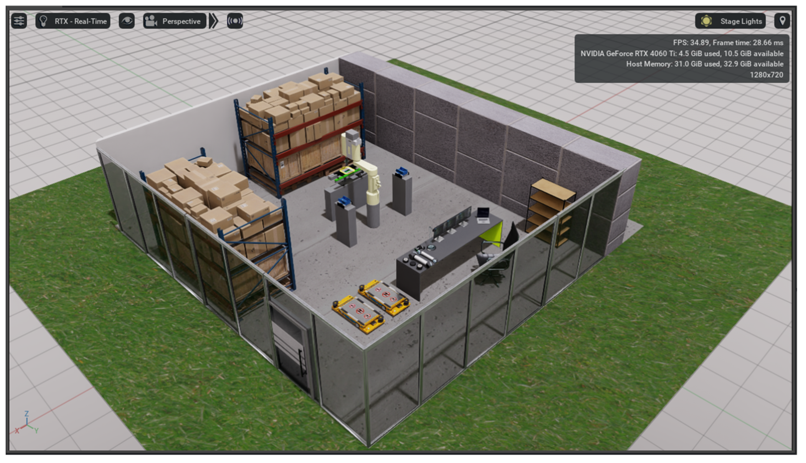
One of the most important steps in the developed methodology is demonstration and testing. Accordingly, this section will present this part step by step. The test itself will be simulated within the Omniverse environment. Our main goal is to integrate the output of the trained architecture into an environment where the robotic arm can perform realistic movements in a simulated manner.
The NVIDIA Omniverse platform [2] is a real-time, physics-based 3D simulation and collaboration platform based on the USD (Universal Scene Description) format [3,50]. It provides the ability to create complex virtual environments and systems where different software and models can be managed in a unified framework.
The software technology itself can be applied in several areas. Of these, industrial robotics will be particularly relevant for us. The platform features a built-in application called ISAAC Sim [51], which was specifically developed to provide realistic physical simulations for robotic arms, mobile robots, and autonomous systems.
The entire scene was stored in USD [50] format, in Xform [52] structure (see Figure 10). The simulation module is capable of reading transformation matrices and then modifying them according to position and rotation. This allows for precise adjustment of the robot arm joint angles and the current state of the components (see Figure 10).

7.2. SONY SRX-611 SCARA Robot Digital-Twin

The SCARA machine unit is based on older hardware, which can now be considered obsolete. The processor is an Intel i486DX2 running the DOS system. This represents a significant limitation in terms of the machine unit’s applicability, making it unsuitable for complex machine learning-based tasks.
However, the machine does not have a TeachPendant either, so we performed general programming tasks via the RS-232 communication port with the help of a USB-to-RS-232 converter.
The SONY SCARA SRX series machine unit has its own programming language. LUNA 5.0 is a special command-based text language. It is specifically designed for programming industrial robot systems. The programming language itself appeared in the industry in the late 1990s.
Its general characteristics include being structured and command-based. Each program runs as a series of instructions. It is primarily limited to motion control and I/O peripheral management.
The LUNA programming language was developed by Sony Corporation to optimize individual production line assembly tasks.
Due to the structure of the program language, it allows for motion control:
  • MOVE, MVS, MVL (point-to-point, linear, and arc motion execution).
  • Fine-tuning speed, acceleration, and deceleration.
  • Storing movement points and coordinates.
Peripheral controls (I/O and system control):
  • Input and output commands (grippers and feeders).
  • Wait function, waiting for a specific signal.
Structure and logic:
  • Label and Jump, program flow control.
  • IF, THEN, ELSE logical decisions based on input signals.
  • LOOK: Performing repetitive tasks and cycles
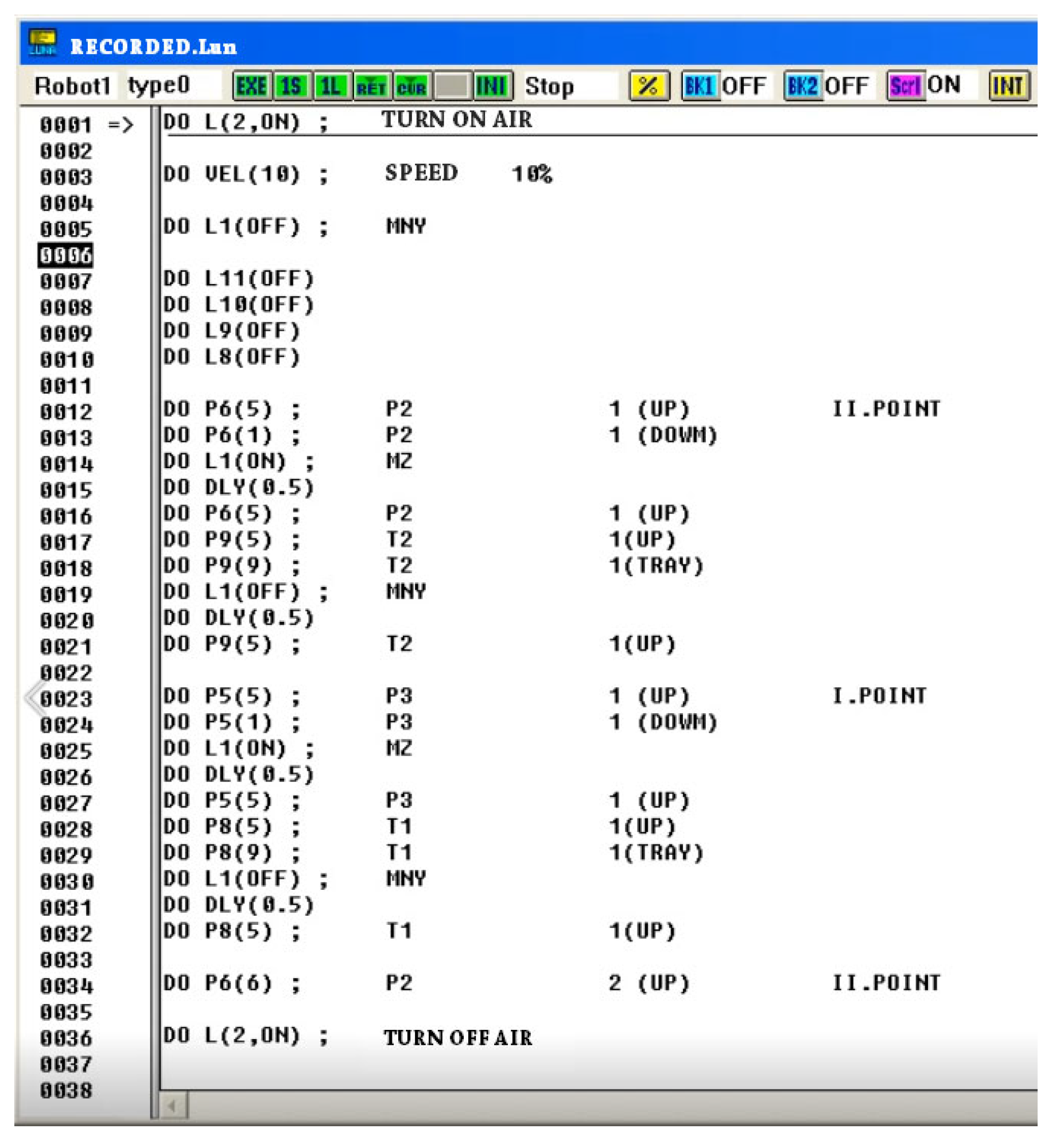
In our case, the sequence is generated by our own algorithm, which contains slots and component locations, as well as robot positions. We translate this sequence to the robot unit using the USB-to-RS232 converter and the robot’s serial communication protocol. Communication is only possible if the settings of the created virtual COM port and the robot controller’s serial port match (see Figure 11).
After that, it is possible to send coordinates via LUNA 5.0. Coordinates do not only mean sending numerical values, but also issuing commands via the Host communication protocol. One method for this is when the Host sends LUNA commands to the robot unit, which define the coordinate points. The LUNA program utilizes position variables for movement points (e.g., P1, P100), which can be overwritten via a serial port.
The SRX PLATFORM IDE environment can only run on the DOS/Windows XP operating systems. However, today’s desktop PCs are no longer able to run these operating systems natively due to various driver errors. For this reason, the necessary operating system was emulated through VMware Player to enable the writing and running of programs for the Sony SCARA SRX-611.
The SONY SRX-611 SCARA machine unit will be modified in the future to expand the range of tasks it can perform and to enable us to carry out PCB panel installation tasks. The machine currently has a PARO QE 01 31-6000 conveyor belt, which will also be modified. Prior to the actual hardware conversion, we created a 3D CAD model of the SONY SRX-611 SCARA, which reflects the current starting conditions. The 3D CAD model elements were then imported into NVIDIA Omniverse, and the model was built. It is essential to note that to reduce the computational requirements, we utilized RGB colors instead of textures for each CAD model.
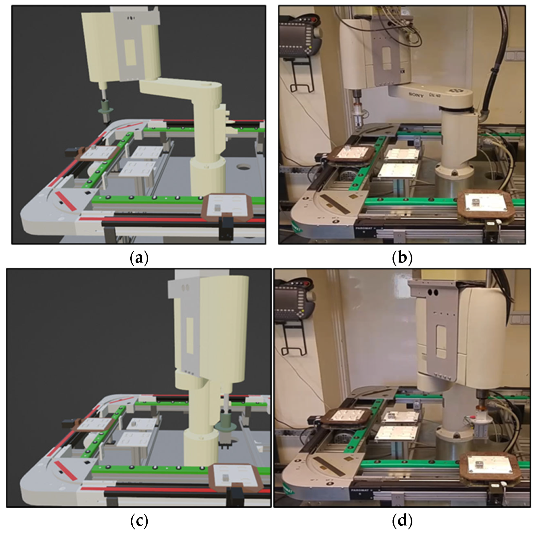
We used the digital twin model created on the Omniverse platform for validation purposes, as the coordinates of the SONY SRX-611 SCARA robot imported into the virtual space can be queried and matched with the real robot (see Figure 12 for details).
In NVIDIA Omniverse, we specified the axis coordinates of the virtual SCARA model based on the actual physical robot. This way, the axis movements performed by the virtual model can later be transferred to the physical machine, as the coordinates can be queried. The deviation between the real and virtual machine units was 0.5–0.6°, which may be due to the 3D CAD model and/or polygon reduction.
For comparison with the virtual model, we designed and manufactured a four-piece cube storage pallet for the SONY SCARA SRX-611 using our proprietary 3D FDM printer. Given that we are discussing an industrial environment, we selected ABS+ industrial filament as the base material. Each pallet can store four 2 cm × 2 cm × 2 cm aluminum cubes. We wrote a sample program to compare the digital twin and the real physical SONY SCARA. Based on the program, it had to move the aluminum cubes from pallet “A” to pallet “B” 50 times. The SCARA performed the placement-transfer cycle with a 98% success rate (49/50).
On the machine side, the error may have resulted from a timing issue, given that RS232 serial communication, data handling, and command processing are all relatively slow.
This is a starting point for us, as prior to the physical modification of the SONY SCARA SRX-611 machine unit, we will perform the necessary modifications and tests virtually in NVIDIA Omniverse so that we can apply them to PCB panel installation tasks.

7.3. Visual Inference, Performance and Real-World Evaluation

The visual perception subsystem of the SCARA Assembly AI was validated both in simulation and on the physical robot.
A Tapo C200 RGB camera was mounted 1.5 m above the working area, aligned perpendicularly to the assembly surface (see Figure 13 for details).
At its native 1920 × 1080 px resolution and an 82° horizontal field of view, the observed ground coverage is approximately 2.0 m × 1.1 m, corresponding to a spatial resolution of ≈1 mm/px.
Considering the detector’s ± 2 px localization variance, this results in an estimated ± 1–2 mm positional tolerance, which is well within the acceptable precision for the SCARA robot’s mechanical accuracy.
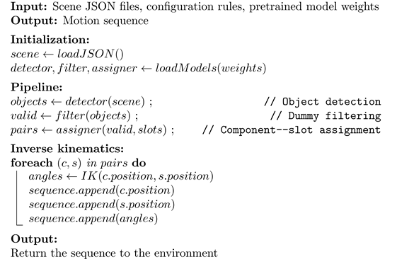
The next step was to incorporate the SCARA Assembly AI algorithm, the main steps of which are shown in the following pseudocode (see Algorithm 1).
Algorithm 1: SCARA Assembly AI method
Robotics 14 00175 i001
When initializing the scene, the first step is to load the JSON files describing the scene, the associated model files, and the configuration file containing the layout rules. During the initialization of the algorithm, the second step involves loading the weight files of previously trained models. In the third step, the algorithm executes the given frame on the architecture, and the individual model components process and transfer data structures to one other. As a fourth step, based on the previously calculated assignment list, we use inverse kinematics to calculate the joint angle values corresponding to the component–slot pairs and compile a sequence. The implementation of inverse kinematic calculations is based on the equations defined in Section 3. As a final step, we return the calculated values to the environment and check that the components are in the correct positions.
Table 13 summarizes the timing results of each stage of the SCARA Assembly AI pipeline.
The total end-to-end inference time remains below 12 ms per scene, corresponding to approximately 85 FPS, confirming that the integrated architecture satisfies real-time operational requirements for robotic assembly.
During simulation, the same camera configuration was replicated in NVIDIA Omniverse, where the rendered synthetic frames were processed in real time by the trained detection and assignment networks.
Based on the measured module-wise latency (Table 14) and the serial communication bandwidth of 115,200 baud, the full perception–assignment–control loop completes within approximately 16 ms per cycle. The method requires around 12 ms in total, while transmitting the 46-byte motion command to the SCARA controller adds only about 4 ms. This corresponds to an effective control rate of roughly 60–65 Hz, confirming that the proposed architecture comfortably satisfies real-time constraints for industrial assembly.
This processing rate ensures full real-time operation, as the physical SCARA robot performs a complete pick-and-place cycle every 3–4 s (see Table 13 for details).
Considering both the neural pipeline (≈12 ms) and the serial transmission delay at 115,200 baud (≈4 ms), the total perception–assignment–control cycle completes in approximately 16 ms per frame, corresponding to an effective control rate of ≈62 FPS.
To assess noise robustness, additional inference tests were carried out on domain-randomized synthetic frames with variations in brightness, contrast, motion blur, and HSV color shifts.
Across 500 perturbed samples, the average accuracy degradation remained within 6–8%, confirming that the perception module maintains stable performance and reliable detection under realistic sensor noise and illumination changes.
These findings confirm that the perception subsystem can be seamlessly integrated into both simulated and physical environments. The near-identical performance observed in Omniverse and on the real SCARA platform demonstrates that the proposed framework preserves its accuracy and timing characteristics across the simulation-to-real transition.
The achieved real-time inference rate of approximately 62 FPS (≈16 ms latency) and the millimeter-level positional precision validate the feasibility of deploying the trained perception and assignment models directly on industrial hardware for future PCB assembly tasks. The complete validation process was carried out iteratively through multiple simulation–real feedback cycles. After each experimental run, discrepancies between simulated and physical performance were analyzed to refine the perception parameters and camera calibration. This iterative validation loop ensured convergence of both spatial accuracy and real-time performance prior to final deployment.
Table 15 presents the overall evaluation, and the complete SCARA Assembly AI algorithm consistently demonstrates high performance across all perception and decision-making modules. The YOLOv8s-Seg detector achieves an average accuracy of 97.9% under both synthetic and real-world conditions, while the Visual Filter Network maintains 97.4% accuracy despite domain-randomized visual noise.
The Assignment Network, optimized with α = 1.0, achieves 96.9% accuracy across unseen layouts and real-world validation samples. The integrated perception–assignment pipeline executes within ≈16 ms per cycle (≈62 FPS), including serial communication with the SCARA controller, ensuring fully real-time operation.
Physical validation on the SONY SCARA SRX-611 platform confirmed a 98% successful assembly rate, demonstrating that the trained models can be deployed directly on industrial hardware without additional calibration or fine-tuning.
The method has some limitations. For more complex layouts, data generation requires higher computational resources, and assignment accuracy depends strongly on the variability of training data. Future work plans will focus on extending the method to three-dimensional tasks and integrating reinforcement learning-based control strategies.

8. Conclusions

This paper presented a modular architecture for modeling and training an industrial SCARA robot (SONY SRX-611) to perform assembly tasks by integrating synthetic data generation, deep learning, and simulation environments. The proposed algorithm comprises several interdependent modules, including a rule-based data generation and annotation module, a PyTorch Lightning-based data module, a component-filtering network with MLP and attention mechanisms, and a Set Transformer-based assignment network that utilizes the Soft Hungarian loss. The results demonstrate that transformer-based assignment networks can accurately learn bijective mappings between components and slots, while the NVIDIA Omniverse integration enabled visual validation and direct comparison with real SCARA executions. Overall, the presented approach establishes a unified framework for combining synthetic data, deep learning, and industrial robotics, validated both in simulation and on real hardware, forming a solid foundation for scalable and adaptive assembly automation systems.

Author Contributions

Conceptualization, T.P.K. software and formal analysis; T.I.E. methodology; M.A. visualization; A.H. and G.H. review and validation. All authors have read and agreed to the published version of the manuscript.

Funding

This research was funded by University of Debrecen.

Data Availability Statement

The original contributions presented in the study are included in the article, further inquiries can be directed to the corresponding author.

Acknowledgments

The authors would like to thank the editor and reviewers for their helpful comments and suggestions, as well as the Doctoral School of Informatics of the University of Debrecen and the Department of Vehicles Engineering of the Faculty of Engineering for infrastructural support. OpenAI ChatGPT, version GPT-4o was used for formalization and stylization.

Conflicts of Interest

The authors declare no conflicts of interest.

References

  1. Tobin, J.; Fong, R.; Ray, A.; Schneider, J.; Zaremba, W.; Abbeel, P. Domain Randomization for Transferring Deep Neural Networks from Simulation to the Real World. arXiv 2017, arXiv:1703.06907. [Google Scholar] [CrossRef]
  2. NVIDIA Corporation. NVIDIA Omniverse Platform—A Simulation and Collaboration Framework for 3D Workflows; NVIDIA Developer: Santa Clara, CA, USA, 2024; Available online: https://developer.nvidia.com/nvidia-omniverse (accessed on 4 October 2025).
  3. NVIDIA Corporation. Omniverse Replicator: Synthetic Data Generation Framework; NVIDIA Developer: Santa Clara, CA, USA, 2024; Available online: https://developer.nvidia.com/omniverse/replicator (accessed on 4 October 2025).
  4. Kaigom, E.G. Potentials of the Metaverse for Robotized Applications in Industry 4.0 and Industry 5.0. Procedia Comput. Sci. 2024, 232, 1829–1838. [Google Scholar] [CrossRef]
  5. Pasanisi, D.; Rota, E.; Ermidoro, M.; Fasanotti, L. On Domain Randomization for Object Detection in Real Industrial Scenarios Using Synthetic Images. Procedia Comput. Sci. 2023, 217, 816–825. [Google Scholar] [CrossRef]
  6. Kuhn, H.W. The Hungarian Method for the assignment problem. Nav. Res. Logist. Q. 1955, 2, 83–97. [Google Scholar] [CrossRef]
  7. Yu, T.; Ma, J.; Yang, H.; Xu, C.; Wang, Z.; Liu, J. Deep Graph Matching with Channel-Independent Embedding and Hungarian Attention. In Proceedings of the International Conference on Learning Representations (ICLR 2020), Addis Ababa, Ethiopia, 26–30 April 2020. [Google Scholar]
  8. Garcia-Najera, A.; Brizuela, C.A. PCB Assembly: An Efficient Genetic Algorithm for Slot Assignment and Component Pick and Place Sequence Problems. In Proceedings of the 2005 IEEE Congress on Evolutionary Computation (CEC’05), Edinburgh, UK, 2–5 September 2005; pp. 1485–1492. [Google Scholar] [CrossRef]
  9. Ahmadi, R.; Osman, I.H. Component Allocation for Printed Circuit Board Assembly Using Modular Placement Machines. Int. J. Prod. Res. 2002, 40, 3545–3562. [Google Scholar] [CrossRef]
  10. Wu, Y.Z.; Ji, P. Optimizing feeder arrangement of a PCB assembly machine for multiple boards. In Proceedings of the 2010 IEEE International Conference on Industrial Engineering and Engineering Management, Macao, China, 7–10 December 2010; pp. 2343–2347. [Google Scholar] [CrossRef]
  11. Li, W.; Xu, A.; Wei, M.; Zuo, W.; Li, R. Deep Learning-Based Augmented Reality Work Instruction Assistance System for Complex Manual Assembly. J. Manuf. Syst. 2024, 73, 307–319. [Google Scholar] [CrossRef]
  12. Peng, X.B.; Andrychowicz, M.; Zaremba, W.; Abbeel, P. Sim-to-Real Transfer of Robotic Control with Dynamics Randomization. In Proceedings of the 2018 IEEE International Conference on Robotics and Automation (ICRA), Brisbane, Australia, 21–25 May 2018; pp. 1–8. [Google Scholar] [CrossRef]
  13. James, S.; Davison, A.J.; Johns, E. Transferring End-to-End Visuomotor Control from Simulation to Real World for Robotic Manipulation. In Proceedings of the 1st Conference on Robot Learning (CoRL 2017), Mountain View, CA, USA, 13–15 November 2017; pp. 334–343. [Google Scholar]
  14. Zhang, S.; Wang, Y.; Chen, Q. Research on Robotic Peg-in-Hole Assembly Method Based on Deep Reinforcement Learning. Appl. Sci. 2025, 15, 2143. [Google Scholar] [CrossRef]
  15. Mena, G.E.; Belanger, D.; Linderman, S.; Snoek, J. Learning Latent Permutations with Gumbel–Sinkhorn Networks. arXiv 2018, arXiv:1802.08665. [Google Scholar] [CrossRef]
  16. Sarlin, P.-E.; DeTone, D.; Malisiewicz, T.; Rabinovich, A. SuperGlue: Learning Feature Matching with Graph Neural Networks. In Proceedings of the IEEE/CVF Conference on Computer Vision and Pattern Recognition (CVPR) 2020, Seattle, WA, USA, 13–19 June 2020. [Google Scholar] [CrossRef]
  17. Lee, J.; Lee, Y.; Kim, J.; Kosiorek, A.R.; Choi, S.; Teh, Y.W. Set Transformer: A Framework for Attention-Based Permutation-Invariant Neural Networks. In Proceedings of the 36th International Conference on Machine Learning (ICML 2019), Long Beach, CA, USA, 9–15 June 2019; pp. 3744–3753. [Google Scholar] [CrossRef]
  18. Zhou, W.; Yi, X.; Zhou, C.; Li, C.; Ye, Z.; He, Q.; Gong, X.; Lin, Q. Feature Importance Evaluation-Based Set Transformer and KAN for Steel Plate Fault Detection. IEEE Trans. Instrum. Meas. 2025, 74, 3555113. [Google Scholar] [CrossRef]
  19. Carion, N.; Massa, F.; Synnaeve, G.; Usunier, N.; Kirillov, A.; Zagoruyko, S. End-to-End Object Detection with Transformers. In Proceedings of the 16th European Conference on Computer Vision (ECCV 2020), Glasgow, UK, 23–28 August 2020; pp. 213–229. [Google Scholar] [CrossRef]
  20. Jia, C.; Liu, H.; Wang, X.; Zhang, Y.; Zhang, Z.; Zhang, L. DETRs with Hybrid Matching. In Proceedings of the IEEE/CVF Conference on Computer Vision and Pattern Recognition (CVPR 2023), Vancouver, BC, Canada, 17–24 June 2023; pp. 19702–19712. [Google Scholar] [CrossRef]
  21. Calzada-Garcia, A.; Victores, J.G.; Naranjo-Campos, F.J.; Balaguer, C. A Review on Inverse Kinematics, Control and Planning for Robotic Manipulators with and Without Obstacles via Deep Neural Networks. Algorithms 2025, 18, 23. [Google Scholar] [CrossRef]
  22. Calzada-Garcia, A.; Victores, J.G.; Naranjo-Campos, F.J.; Balaguer, C. Inverse Kinematics for Robotic Manipulators via Deep Neural Networks: Experiments and Results. Appl. Sci. 2025, 15, 7226. [Google Scholar] [CrossRef]
  23. Bouzid, R.; Gritli, H.; Narayan, J. ANN Approach for SCARA Robot Inverse Kinematics Solutions with Diverse Datasets and Optimisers. Appl. Comput. Syst. 2024, 29, 24–34. [Google Scholar] [CrossRef]
  24. Cheah, C.C.; Wang, D.Q. Region Reaching Control of Robots: Theory and Experiments. In Proceedings of the 2005 IEEE International Conference on Robotics and Automation, Barcelona, Spain, 18–22 April 2005; pp. 974–979. [Google Scholar] [CrossRef]
  25. SCARA Robots: Robot Hall of Fame. Available online: http://www.robothalloffame.org/inductees/06inductees/scara.html (accessed on 23 December 2024).
  26. PARO QE 01 31-6000; Manual of the Modular Conveyor. PARO AG: Subingen, Switzerland, 2016.
  27. Kapusi, T.P.; Erdei, T.I.; Husi, G.; Hajdu, A. Application of Deep Learning in the Deployment of an Industrial SCARA Machine for Real-Time Object Detection. Robotics 2022, 11, 69. [Google Scholar] [CrossRef]
  28. Falcon, W.; The PyTorch Lightning Team. PyTorch Lightning: A Lightweight PyTorch Wrapper for High-Performance AI Research. In Proceedings of the NeurIPS 2019 Workshop on ML Systems, Vancouver, WA, Canada, 13 December 2019; Available online: https://www.pytorchlightning.ai (accessed on 4 October 2025).
  29. Buslaev, A.; Iglovikov, V.I.; Khvedchenya, E.; Parinov, A.; Druzhinin, M.; Kalinin, A.A. Albumentations: Fast and Flexible Image Augmentations. Information 2020, 11, 125. [Google Scholar] [CrossRef]
  30. Girshick, R.; Donahue, J.; Darrell, T.; Malik, J. Rich Feature Hierarchies for Accurate Object Detection and Semantic Segmentation. In Proceedings of the IEEE Conference on Computer Vision and Pattern Recognition (CVPR 2014), Columbus, OH, USA, 23–28 June 2014; pp. 580–587. [Google Scholar] [CrossRef]
  31. Girshick, R. Fast R-CNN. In Proceedings of the IEEE International Conference on Computer Vision (ICCV 2015), Santiago, Chile, 7–13 December 2015; pp. 1440–1448. [Google Scholar] [CrossRef]
  32. Ren, S.; He, K.; Girshick, R.; Sun, J. Faster R-CNN: Towards Real-Time Object Detection with Region Proposal Networks. In Proceedings of the 28th International Conference on Neural Information Processing Systems (NeurIPS 2015), Montreal, QC, Canada, 7–12 December 2015; pp. 91–99. [Google Scholar] [CrossRef]
  33. He, K.; Gkioxari, G.; Dollár, P.; Girshick, R. Mask R-CNN. In Proceedings of the IEEE International Conference on Computer Vision (ICCV 2017), Venice, Italy, 22–29 October 2017; pp. 2961–2969. [Google Scholar] [CrossRef]
  34. Redmon, J.; Divvala, S.; Girshick, R.; Farhadi, A. You Only Look Once: Unified, Real-Time Object Detection. In Proceedings of the IEEE Conference on Computer Vision and Pattern Recognition (CVPR 2016), Las Vegas, NV, USA, 27–30 June 2016; pp. 779–788. [Google Scholar] [CrossRef]
  35. Liu, W.; Anguelov, D.; Erhan, D.; Szegedy, C.; Reed, S.; Fu, C.Y.; Berg, A.C. SSD: Single Shot MultiBox Detector. In Proceedings of the European Conference on Computer Vision (ECCV 2016), Amsterdam, The Netherlands, 8–16 October 2016; pp. 21–37. [Google Scholar] [CrossRef]
  36. Lin, T.-Y.; Goyal, P.; Girshick, R.; He, K.; Dollár, P. Focal Loss for Dense Object Detection. In Proceedings of the IEEE International Conference on Computer Vision (ICCV 2017), Venice, Italy, 22–29 October 2017; pp. 2999–3007. [Google Scholar] [CrossRef]
  37. Han, K.; Wang, Y.; Chen, H.; Chen, X.; Guo, J.; Liu, Z.; Tang, Y.; Xiao, A.; Xu, C.; Xu, Y.; et al. Object Detection with Transformers: A Review. arXiv 2023, arXiv:2306.04670. [Google Scholar] [CrossRef]
  38. Li, F.; Zhang, H.; Liu, S.; Guo, J.; Ni, L.; Zhang, C.; Ni, B.; Wang, L.; Lu, H.; Hu, H.; et al. DN-DETR: Accelerate DETR Training by Introducing Query DeNoising. In Proceedings of the IEEE/CVF Conference on Computer Vision and Pattern Recognition (CVPR 2022), New Orleans, LA, USA, 19–24 June 2022; pp. 13619–13627. [Google Scholar] [CrossRef]
  39. Lv, W.; Song, G.; Yu, H.; Ma, C.; Pang, Y.; Zhang, C.; Wei, Y. DINO: DETR with Improved DeNoising Anchor Boxes for End-to-End Object Detection. In Proceedings of the International Conference on Learning Representations (ICLR 2023), Kigali, Rwanda, 1–5 May 2023. [Google Scholar] [CrossRef]
  40. Wei, Y.; Lv, W.; Ma, C.; Liu, Y.; Zhang, C.; Zhang, Y.; Pang, Y.; Song, G. RT-DETR: Real-Time DETR with Efficient Hybrid Encoder. arXiv 2023, arXiv:2304.08069. [Google Scholar] [CrossRef]
  41. Zhao, Y.; Lv, W.; Xu, S.; Wei, J.; Wang, G.; Dang, Q.; Liu, Y.; Chen, J. DETRs Beat YOLOs on Real-time Object Detection. In Proceedings of the 2024 IEEE/CVF Conference on Computer Vision and Pattern Recognition (CVPR), Seattle, WA, USA, 16–22 June 2024; pp. 16965–16974. [Google Scholar] [CrossRef]
  42. Jocher, G. YOLOv8: Real-Time Object Detection and Instance Segmentation. Ultralytics. 2023. Available online: https://github.com/ultralytics/ultralytics (accessed on 5 November 2025).
  43. Yu, T.; Wang, R.; Yan, J.; Li, B. Learning Deep Graph Matching via Channel-Independent Embedding and Hungarian Attention. In Proceedings of the 8th International Conference on Learning Representations (ICLR 2020), Addis Ababa, Ethiopia, 26–30 April 2020; Available online: https://api.semanticscholar.org/CorpusID:214361872 (accessed on 23 November 2025).
  44. Hodaň, T.; Haluza, P.; Obdržálek, Š.; Matas, J.; Lourakis, M.; Zabulis, X. T-LESS v2: An RGB-D Dataset for 6D Pose Estimation of Texture-less Objects. In Proceedings of the IEEE Winter Conference on Applications of Computer Vision (WACV), Santa Rosa, CA, USA, 24–31 March 2017; pp. 880–888. [Google Scholar] [CrossRef]
  45. Hinterstoisser, S.; Lepetit, V.; Ilic, S.; Holzer, S.; Bradski, G.; Konolige, K.; Navab, N. Model-Based Training, Detection and Pose Estimation of Texture-less 3D Objects in Heavily Cluttered Scenes. In Proceedings of the 14th Asian Conference on Computer Vision (ACCV), Daejeon, Republic of Korea, 5–9 November 2012. [Google Scholar] [CrossRef]
  46. Tyree, S.; Tremblay, J.; To, T.; Cheng, J.; Mosier, T.; Smith, J.; Birchfield, S. 6-DoF Pose Estimation of Household Objects for Robotic Manipulation: An Accessible Dataset and Benchmark. In Proceedings of the International Conference on Intelligent Robots and Systems (IROS), Kyoto, Japan, 23–27 October 2022; Available online: https://github.com/swtyree/hope-dataset (accessed on 10 November 2025).
  47. NVIDIA Corporation. vMaterials 2: Physically-Based Material Library for NVIDIA Omniverse. Available online: https://developer.nvidia.com/vmaterials (accessed on 4 November 2025).
  48. NVIDIA Corporation. Omniverse Dome Light HDRI Environment Package. Available online: https://developer.nvidia.com/omniverse (accessed on 10 November 2025).
  49. Akiba, T.; Sano, S.; Yanase, T.; Ohta, T.; Koyama, M. Optuna: A next-generation hyperparameter optimization framework. In Proceedings of the 25th ACM SIGKDD International Conference on Knowledge Discovery & Data Mining, Anchorage, AK, USA, 4–8 August 2019; pp. 2623–2631. [Google Scholar] [CrossRef]
  50. Pixar Animation Studios. Universal Scene Description (USD) Specification; Pixar: Emeryville, CA, USA, 2016; Available online: https://openusd.org/release/intro.html (accessed on 3 October 2025).
  51. NVIDIA Corporation. Omniverse Isaac Sim: Robotics Simulation Platform; NVIDIA Developer: Santa Clara, CA, USA, 2024; Available online: https://developer.nvidia.com/isaac-sim (accessed on 4 October 2025).
  52. Pixar Animation Studios. USD Xform Schema—Transforming Prims; Pixar: Emeryville, CA, USA, 2016; Available online: https://openusd.org/release/api/class_usd_geom_xform.html (accessed on 3 October 2025).
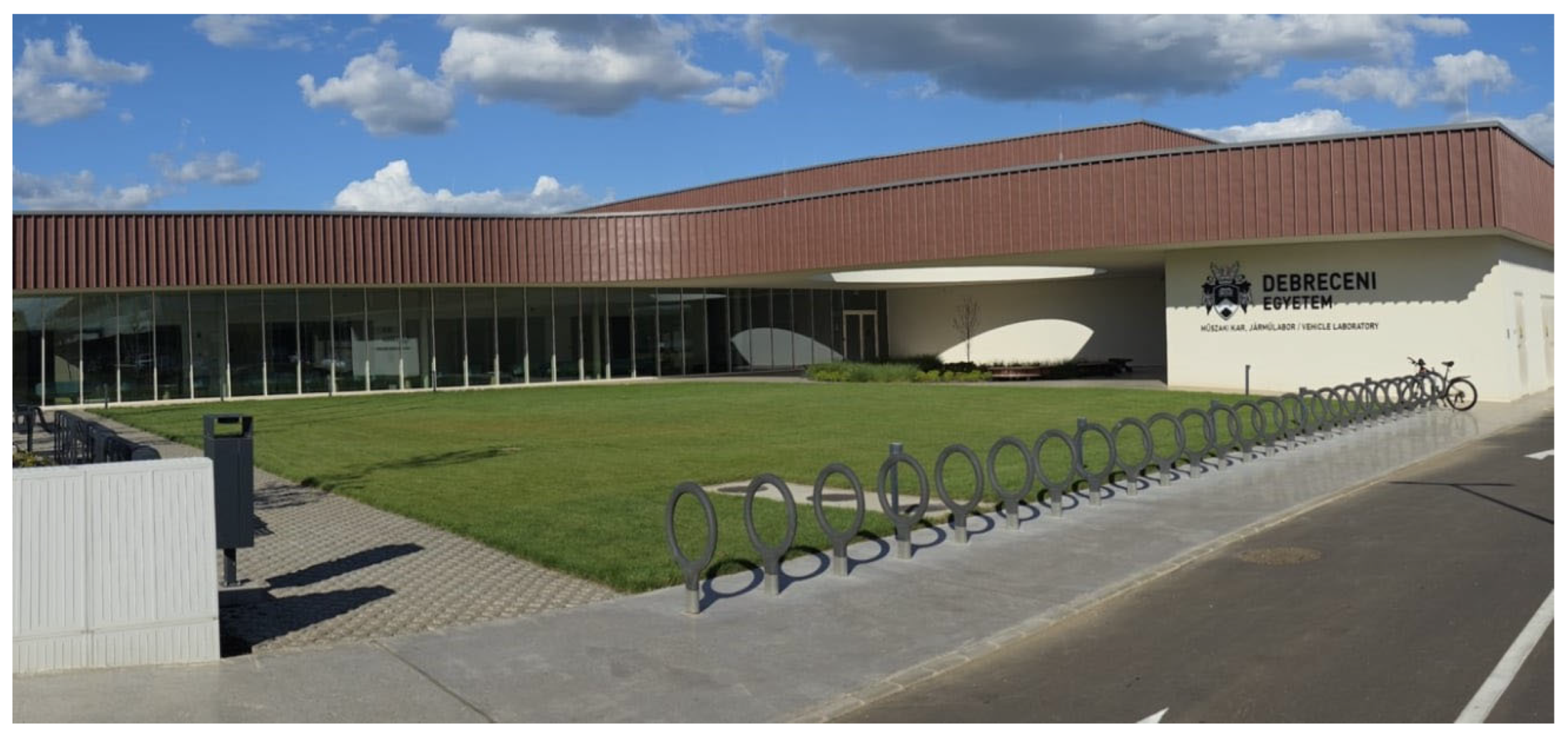
Figure 1. The main building of Vehicle Manufacturing Lab and Research Center.
Robotics 14 00175 g001
Figure 2. The workspace and the corresponding values of robot arms degrees of SCARA robot unit.
Robotics 14 00175 g002
Figure 3. The workspace of robot device and the corresponding subregions.
Robotics 14 00175 g003
Figure 4. Overview of the proposed SCARA Assembly AI framework. The detector localizes all components, the filter removes invalid objects using learned visual–geometric cues, and the assignment network pairs valid components with their target slots.
Robotics 14 00175 g004
Figure 5. Overview of the implemented Synthetic Assembly Data Generator (SADG) module. The system combines 3D assets, scene constraints, and PCB layout definitions to generate three complementary datasets: virtual scenes for detection, binary filtering data, and deterministic assignment pairs for training.
Robotics 14 00175 g005
Figure 6. Architecture of the improved filter network incorporating multimodal features. The component and slot images are processed by a shared CNN-based visual encoder to extract visual embeddings, while corresponding geometric features are provided as parallel inputs. All features are concatenated into a unified 276-dimensional representation, followed by a multihead attention and MLP head to predict the validity of each component–slot pair.
Robotics 14 00175 g006
Figure 7. The architecture of the developed assignment module. Architecture of the visual assignment network. Each component–slot pair is represented by multimodal features, combining visual embeddings from a shared CNN encoder and geometric attributes. Both sets are processed by permutation-invariant Set Transformer encoders (2 × ISAB). The Cross-Multihead Attention Block block fuses information from slot embeddings into the component representations via residual connection. The resulting embeddings are concatenated pairwise and passed through a Multi-layer Perception head to compute the score matrix S R N c × N s .
Robotics 14 00175 g007
Figure 8. Example real images used in the evaluation: (a) A sample object instance from the T-LESS public dataset, representing textureless industrial parts with available 3D CAD models.; (b) A real RGB capture obtained using the TP-Link Tapo C200 camera, showing one of the proprietary components recorded for real-world validation.
Robotics 14 00175 g008
Figure 9. Example synthetized images used in the dataset generation process. (ac) Three synthetic RGB scenes generated with NVIDIA Omniverse Replicator, showing variations in object placement, lighting, and camera pose; (df) Corresponding instance segmentation masks automatically produced during rendering.
Robotics 14 00175 g009
Figure 10. The virtual scene of the lab within the Vehicle Manufacturing Lab and Research Center.
Robotics 14 00175 g010
Figure 11. SRXT Monitor window.
Robotics 14 00175 g011
Figure 12. The digital-twin setup of the SONY SRX-611 SCARA robot. Panels (a,c) show the simulated Omniverse environment, while (b,d) depict the corresponding real-world execution. The identical configurations enable direct comparison between simulated and physical assembly tasks.
Robotics 14 00175 g012
Figure 13. Experimental setup of the SCARA-based assembly station used for real-world validation. The IP camera captures component placement images and streams them via Wi-Fi to the desktop computer running the control and data processing scripts. The SONY SCARA SRX-611 executes the pick-and-place operations based on the detected component–slot pairs.
Robotics 14 00175 g013
Table 2. Data augmentation methods and corresponding parameters.
CategoryNameParameters
Illumination variationRandomBrightnessContrastbrightness_limit = 0.2,
contrast_limit = 0.2,
Sensor noiseGaussNoisevar_limit = (10, 50),
mean = 0,
Motion/focus blurMotionBlur, GaussianBlurblur_limit = 5,
Color shift/illumination temperatureHueSaturationValuehue_shift_limit = 10, sat_shift_limit = 15, val_shift_limit = 10, p = 0.3
RGB channel misalignmentRGBShiftr_shift_limit = 10, g_shift_limit = 10, b_shift_limit = 10
Compression artifactsImageCompressionquality_lower = 40,
quality_upper = 90
Table 3. Training configuration and parameters of the detector models.
ParameterDefault Value(s)
Epochs100
Batch size16
Image size (imgsz)640
OptimizerAdam
Initial learning rate (lr0)0.00025 (backbone: 0.000025)
Momentum/betas(0.9, 0.999)
Weight decay0.05
Warmup stepsabout 1000 iterations
LR schedulercosine decay
Loss weightscls = 1.0, bbox = 5.0, GIoU = 2.0
Table 4. Training and validation results of the detector model.
PSNRYOLOv8-Nano-SegYOLOv8-Small-SegYOLOv11-Nano-SegYOLOv11-Small-Seg
Prec.Recall.mAP50mAP50–95Prec.Recall.mAP50mAP50–95Prec.Recall.mAP50mAP50–95Prec.Recall.mAP50mAP50–95
0.9760.920.970.9060.960.920.970.9140.9910.9530.9820.9150.9890.9630.9840.932
34.100.5920.5010.5340.4280.7190.5730.6750.6670.3690.2760.3150.3070.7240.7200.7690.726
28.210.24310.2630.2230.2160.3990.3190.3090.02990.2440.2120.2240.2120.4410.4700.4260.421
22.480.04310.01630.02230.02160.0190.00320.0110.0090.0430.0010.0220.0210.0040.0070.0020.002
Table 5. Top-5 Optuna Trials for the Visual Filter Network.
RankLearning RateHidden DimEmbed DimCnn BaseCnn LayersCnn DropMlp DropOptimizerVal Acc
17.33 × 10−6128128440.0770.274Adam0.979
24.64 × 10−53216420.0130.121AdamW0.967
32.81 × 10−5321281630.0310.152AdamW0.963
41.02 × 10−61281283220.0460.225Adam0.942
59.93 × 10−664163230.2120.207Adam0.929
Table 6. Hyperparameter Search Space and Sampling Strategy.
ParameterRange/OptionsSampling Type
Learning rate1 × 10−6–5 × 10⁻⁶Log-uniform
Hidden
dimension
(32, 64, 128)Categorical
CNN embedding(16, 64, 128)Categorical
CNN layers2–4Integer
Dropout (CNN/MLP)0.0–0.3Uniform
Optimizer{Adam, AdamW}Categorical
Table 7. Summary of the conducted experimental configurations, including variable and fixed hyperparameters, objectives, and the number of runs for each test category.
Experiment TypeVariable ParametersFixed ParametersPurposeRuns
α-Sensitivityα ∈
{0.0, 0.25, 0.5,0.75 1.0,1.5,2.0}
lr_core = 5 × 10⁻⁵, lr_vis = 1 × 10⁻⁵,
Optimizer = Adam
Soft Hungarian Loss sensitivity analysis. 8
Model-variant comparisonhidden_dim ∈ {256, 384, 512};
embedding_dim ∈ {128, 192}; num_heads ∈ {8, 16}; num_inds ∈ {32, 64}
α = 1.0, lr_core = 5 × 10⁻⁵, lr_vis = 1 × 10⁻⁵Capacity and architectural sensitivity evaluation3
Generalization testLayouts and component types unseen during training; random rotation ± 15°; partial occlusion masksFixed model = best configuration (α = 1.0, hidden = 384)Tests cross-layout and cross-category generalization. 3
Failure-case analysisQualitative inspection of top-N incorrect predictionsFixed best modelIdentifies typical mismatches between visually similar parts or overlapping slots.qualitative
Table 8. Comparison of different assignment strategies on the validation set. The proposed Set Transformer and Soft Hungarian Loss architecture significantly outperforms both the deterministic and attention-augmented baselines in all metrics, confirming the benefit of joint visual–geometric learning.
MethodApproach TypePrecisionAccuracyRecallF1-Score
Rule-based
Hungarian
Deterministic cost-matrix matching using IoU and centroid distance0.0600.0310.0310.041
Hungarian AttentionVisual-feature-weighted Hungarian matching (non-learned attention)0.8200.7640.7460.781
Proposed Set Transformer and Soft Hungarian LossLearned visual-geometric matching with permutation-invariant transformer0.9660.9240.9140.942
Table 9. Sensitivity analysis of the Soft Hungarian Loss parameter α. Reported values correspond to mean ± standard deviation across three random seeds. The α = 0 configuration (Hungarian + Attention baseline) exhibits low stability and slower convergence, while α ∈ [0.5–2.0] provides both higher accuracy and reduced variance, confirming the robustness of the proposed differentiable matching formulation.
αAccuracyPrecisionRecallF1-ScoreBest
Val Loss
Epoch to Converge
0.00.7490.7210.8450.7630.44218
0.250.8580.8720.9030.8990.34216
0.50.9290.9550.8920.9230.19715
0.750.9160.9680.9110.9200.21114
1.00.9470.9790.9420.9550.27415
1.50.9240.9430.8760.9110.28215
2.00.9180.9590.9100.9370.23715
Table 10. Model-variant comparison of the Visual Assignment Network.
Model VariantHidden DimEmbedding DimHeadsInduced PointsParameters (M)Val. F1 (%)Memory (MB)Inference Time
(ms)
V1 (Light)2561288323.70.854 ± 0.12614.693.42
V2 (Balanced)38412816648.00.878 ± 0.432.0363.67
V3 (Extended)512256166414.20.941 ± 0.2256.793.97
Table 11. Generalization performance of the Visual Assignment Network.
Test ConditionDescriptionPrecisionRecallF1-ScoreAccuracyComments
Unseen layoutCompletely new PCB topology, same component set0.8020.7140.7640.782Maintains stable performance; moderate sensitivity to spatial rearrangement.
Unseen componentsNew component categories excluded from training0.9660.8120.8980.911High precision; recall slightly reduced due to unseen geometric shapes.
Rotated/partial viewsRandom 10–15° rotation and 20% occlusion0.9090.8460.8780.892Robust to rotation and partial occlusion; minor degradation under stronger distortions.
Table 12. Typical failure cases of the Visual Assignment Network.
Failure TypeDescriptionExample CauseImpact on Prediction
Geometric similarityComponents with nearly identical bounding-box shapes and aspect ratios (e.g., identical capacitors)Visual embeddings insufficiently discriminativeFalse-positive matches between visually similar parts
Partial occlusionComponent partially hidden by other object or viewpointMissing features in the visible regionDecreased recall; occasional slot mismatch
Rotational ambiguitySymmetric components rotated by 180° produce similar featuresOrientation feature underrepresentedWrong slot assigned despite correct region
Clustered layoutsMultiple components densely arranged within small areaOverlapping receptive fields in attentionAssignment confusion among neighboring slots
Texture overdominanceVisual encoder overweights texture compared to geometryTexture randomization insufficientMisclassification of visually noisy samples
Table 13. Estimated inference time of each module in the SCARA Assembly AI pipeline. The complete perception–decision–control sequence executes within approximately 12 ms per scene (≈85 FPS), confirming that the proposed architecture satisfies real-time operational requirements for robotic assembly tasks.
ModuleOperationTime [ms]Comment
Detector (YOLOv8s-Seg)Object detection and instance segmentation4.2 ± 0.2Primary perception stage
Crop extractionROI slicing from detected masks0.5 ± 0.1Torch tensor-based cropping
Visual Filter NetworkDummy vs. valid classification1.5 ± 0.4Lightweight attention-based CNN
Assignment NetworkComponent–slot pairing3.7 ± 0.5SetTransformer with Soft Hungarian Loss
Inverse Kinematics (IK)Angle computation for (c,s) pairs0.7 ± 0.2Trigonometric forward pass
TotalFull pipeline inference12.0 ± 1.0≈85 FPS on RTX 4060 Ti
Table 14. End-to-end real-time performance of the SCARA Assembly AI pipeline under various visual conditions. The combined perception–filtering–assignment–control loop, including serial transmission at 115,200 baud, operates at approximately 16 ms per cycle (≈60–62 FPS).
Test ConditionEnvironmentThroughput (FPS)Latency (ms/Frame)Accuracy [%]ΔAcc vs. Nominal [%]Notes
Normal lightingOmniverse621697.9Reference
Brightness +20%Omniverse621696.3–1.6Robust
Motion blurOmniverse6116–1793.8–4.1Slight degradation
HSV shiftOmniverse6116–1792.2–5.7Color perturbation
Real-world Tapo feedPhysical621696.9–1.0Consistent performance
Table 15. Overall evaluation summary of the SCARA Assembly AI framework across detection, filtering, assignment, and real-world validation stages. The integrated system achieves high accuracy (≈97%) and real-time operation (≈16 ms per cycle), maintaining consistent performance across both simulated and physical environments.
ModuleEnvironmentKey MetricPerformanceRemarks
Detection (YOLOv8s-Seg)Omniverse and RealAccuracy97.9%Stable under domain transfer
Filter NetworkSynthetic onlyAccuracy97.4%Robust to visual noise
Assignment NetworkSynthetic and RealAccuracy96.9%Best at α = 1.0 configuration
Simulation inferenceOmniverseLatency/Throughput16 ms/≈62 FPSReal-time capable
Real-world testSCARA SRX-611Success rate98%Physical validation on robot hardware
Disclaimer/Publisher’s Note: The statements, opinions and data contained in all publications are solely those of the individual author(s) and contributor(s) and not of MDPI and/or the editor(s). MDPI and/or the editor(s) disclaim responsibility for any injury to people or property resulting from any ideas, methods, instructions or products referred to in the content.