Article

Optimizing Automated Battery Demanufacturing Through Simulation-Based Analysis and Genetic Algorithm

1
Department of Engineering Sciences, University of Agder, 4604 Kristiansand, Norway
2
Department of Information and Communication Technology, University of Agder, 4604 Kristiansand, Norway
*
Authors to whom correspondence should be addressed.
Robotics 2025, 14(11), 156; https://doi.org/10.3390/robotics14110156
Submission received: 9 September 2025 / Revised: 20 October 2025 / Accepted: 21 October 2025 / Published: 28 October 2025
(This article belongs to the Section Industrial Robots and Automation)

Abstract

The automation of recycling processes for electric vehicle lithium-ion battery packs is crucial for the advancement of green energy transportation. Testing disassembly strategies on real equipment is time consuming, expensive, and poses significant safety risks. This paper presents a novel simulation-based framework that leverages the integration of a high-fidelity virtual environment with a Robot Operating System (ROS) to visualize and accurately calculate the time required for complex robotic disassembly operations. The calculated operation times are then used as input for genetic algorithm optimization to improve process efficiency. The results demonstrate that automation significantly improves the total speed of the disassembly process compared to manual methods. By utilizing this novel simulation and optimization approach, a 25% improvement in performance was achieved for the pack-to-module disassembly stage. This method provides a safe and cost-effective approach for process design, contributing directly to the development of a circular economy and supporting the transition towards sustainable transportation.

1. Introduction

The automation of processes offers many advantages over manual methods ranging from safety and productivity to handling large volumes and improved economics. In demanufacturing, automation has gained a strong foothold due to the ongoing focus on sustainability and recycling. Within the battery recycling context, the “demanufacturing” process refers to the whole process of preparing the battery pack for recycling; i.e., discharging and characterization, disassembling it into modules and/or cells, and recycling the cells to obtain the materials (plastic, metals, etc.) for further use.
Simulation environments (software-generated 3D virtual world representing a real application) are widely used in robotics for testing, updating, planning, and demonstrating, before physical implementation. This process is often referred to as “offline programming” [1]. Performing planning in an environment separated from real robots saves the need for downtime, as the robotic manipulator would otherwise have to be taken out of the production line for configuration. This approach is highly cost-effective and time-efficient, allowing new implementations to be applied in a virtual system via simulation before testing them on the actual production line. Simulations can also predict malfunctions, collisions, and other accidents, thereby preventing damage to real equipment.
A number of simulation programs for robotics are available today. Gazebo, as it is pre-installed in the Robot Operating System (ROS), is the first robotic simulation environment one comes across when working with ROSs. Gazebo is an open-source simulator which includes a physics engine and provides the ability to emulate sensors that can perceive the environment. The ROS provides full support for the simulation of robotics using this software. Unity and Unreal engine are both video game engines that have been used extensively for making and programming video games. Lately, both have been slowly expanding into the area of robotics, providing a high graphics-based environment for visualization. Unity and Unreal engine both have a physics engine and are able to connect to the ROS.
Although Unity has been used in several studies in relation to ROSs, most of the studies published focus on VR applications [2]. There is also limited publication of multi-robot simulations in ROS and Unity. There are however a number of cases where single-robot implementations have been developed. A Unity environment controlled by a ROS is created in [3] for controlling an industrial robot with a camera sensor. In [4], a Unity-based robotic simulation is created for a single robot with two manipulator arms, controlled by a VR interface and using the ROS as middleware for the connection. The ROS sharp package is used for connecting a ROS and Unity, and although two manipulator arms were used in this case, they were considered a single robot, originating from a single URDF file by the ROS. Finally, a comparison of Unity with Gazebo for simulating ROS-controlled robots is made in [5]. Besides the more detailed depiction of the graphical part of the simulation, Unity also provides a highly flexible environment and the ability to include plugins which are useful for machine learning and other possible applications. A more realistic representation can be achieved in Unity, as it provides a High-Definition Rendering Pipeline (HDRP) which can be used to create a high-end graphics environment. A hybrid approach to rendering is used which supports rasterised, ray tracing, and path tracing rendering techniques. It is however incompatible with many elements used in a traditional Unity project, most notably the materials. All materials using the normal rendering pipeline in a project need to be converted to HDRP materials during implementation of the HDRP to an already existing project. In addition, many assets purchased from Unity Asset’s store, which are worthwhile for developing realistic virtual world kinematics and animations, are not supported in an HDRP environment due to compatibility issues.
Some previous work on robotic disassembly focuses on human–robot collaboration [6,7,8,9] where the collaborative robot performs only the most repetitive and simple tasks. A comprehensive review on dynamic recycling of EV LIB batteries is presented in [10] to manage uncertainty in the recycling process [11]. Other papers propose cognitive fully automated robotic disassembly but only consider one robotic cell, i.e., one disassembly place [12,13] and optimize the operations and material recovery within this cell. When considering the entire demanufacturing automated line that includes discharging, characterization, pack-to-module disassembly, sorting, and module-to-cell disassembly, several workstations are necessary, as mentioned in [6], with roll conveyors for transporting material between them. The disassembly task planner presented in [14] has been extended in [13] to include a disassembly strategy optimiser when data about the product, the disassembly process, and the market are available. The sensorial system alone is not able to provide all of the information for the required database and the gap must be closed by the mean of several disassembly experiments or expertise gained from similar past batteries. The main research focus of this paper is therefore to create a simulator within a virtual environment to visualize and test different demanufacturing strategies; obtain some of the necessary data, such as, for example, process times (disassembly and transportation) or disassembly tools, without the need of physical experiments; and isolate potential bottlenecks in the disassembly strategies. In [15], the potential for an automated disassembly process for 530 BEV batteries was investigated, highlighting the importance of optimizing disassembly strategies in the context of full automation versus human–robot collaboration. To manage the uncertain and dynamic conditions of end-of-life product recycling and maximize efficiency, a novel approach utilizes a digital twin-assisted multi-agent human–robot collaboration (HRC) disassembly system to facilitate real-time data management and dynamic task allocation [16].
A number of studies have been been conducted on the dynamic disassembly of end-of-use EV batteries by focusing on screw connection analysis, utilizing parameters like torque and angle data, combined with CNN-GRU deep learning models for detecting co-rotation and other disassembly anomalies [17]. To enhance the production efficiency of EV battery recycling and mitigate resource waste, research has focused on sequence optimization that accounts for the inherent uncertainty of battery pack quality and structure. For instance, a dynamic disassembly Bayesian network has been employed to achieve dynamic process optimization and sequence selection for massive EV battery disassembly [18].
By utilizing Unity3D 2020.3 for simulation, valuable disassembly information can be obtained that aids in optimizing processes, such as the disassembly of EV batteries. To achieve this, the procedure is divided into discrete tasks such as removing the casing, disconnecting electrical components, and segregating recyclable materials, aiming to organize these steps to minimize overall processing time and enhance productivity. This process, usually modeled as a job shop scheduling problem or a variant thereof, involves machines or humans processing various jobs. While each machine can handle only one job at a time, multiple machines or humans can work in parallel when possible, accommodating different requirements and speeds. There are various approaches to solve job shop problems, such as genetic algorithms (GAs) [19,20] and reinforcement learning [21]. GAs are particularly effective for this problem, allowing for the fine-tuning of parameters like population size, mutation rate, and selection criteria to match the specific characteristics of the batteries being disassembled, thereby ensuring efficiency and tailored solutions for different battery types.
The utilization of the Unity 3D simulation environment in this research represents a strategic approach distinctly different from that of a digital twin, while highlighting its unique importance in the field. Unity 3D, known for its high-fidelity graphical capabilities, provides a controlled virtual space ideal for visualizing complex robotic processes and interactions. This platform is particularly beneficial in scenarios requiring detailed visual and physical interactions, such as in robotics and demanufacturing processes. Unlike a digital twin, which offers a dynamic model mirroring a physical system in real time, the Unity 3D environment is tailored to simulating specific scenarios in a static, predefined setting, focusing on the initial planning and testing phases of robotic applications. In robotic disassembly, the Unity 3D environment enables the in-depth exploration and optimization of processes before actual implementation. It stands as an invaluable tool for scenario testing, offering detailed graphics, advanced technology integration, and adaptability to various configurations. While it does not inherently provide continuous, real-time monitoring like a digital twin, it allows for concentrated effort on design, testing, and visualization phases, crucial for any robotic system or disassembly process. Consequently, the research with Unity 3D complements the long-term operational insights offered by digital twins, establishing a necessary and distinct niche in the field of robotics and demanufacturing.
This research focuses on simulating the real-world disassembly process, including planning the disassembly sequence, executing it in real time (or near-real time), and generating time-based data that closely reflects the actual process. As a case study, a genetic algorithm is used to optimize the overall processing time.
The rest of this paper is organized as follows. In Section 2, we present the robotic cell design for the demanufacturing line and the methods used for time calculations and optimization. Section 3 discusses the case study and results, focusing on a detailed description of the disassembly process for an EV battery pack. Section 4 provides insights and discussions on the findings, while Section 5 concludes with future directions and improvements for optimizing the robotic disassembly process.

2. Methods

This section presents the robotic cell design for the demanufacturing line, the simulation components, the methods used to calculate the operating time and the optimization of the disassembly sequence between multiple robots.

2.1. Robotic Cell Design

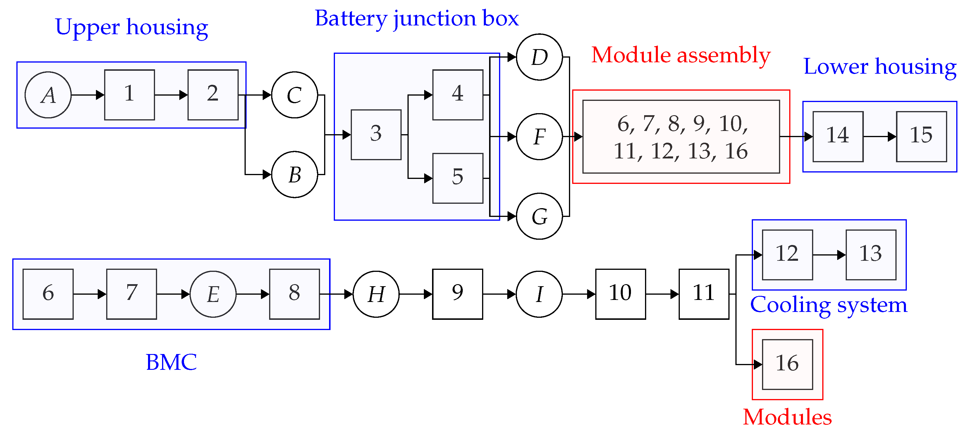
This subsection explores the design and layout of a robotic cell specifically engineered for the disassembly of all types of EV battery packs. While the focus is on a single EV LIB pack model for the purposes of simulation, visualization, operation time calculations, and optimization of the disassembly sequence, the overarching goal is to efficiently convert battery packs into either reusable modules with sufficient remaining life or individual cells for further recycling. This objective is accomplished through a sequence of four subtasks and one test, as detailed in the process flow depicted in Figure 1.
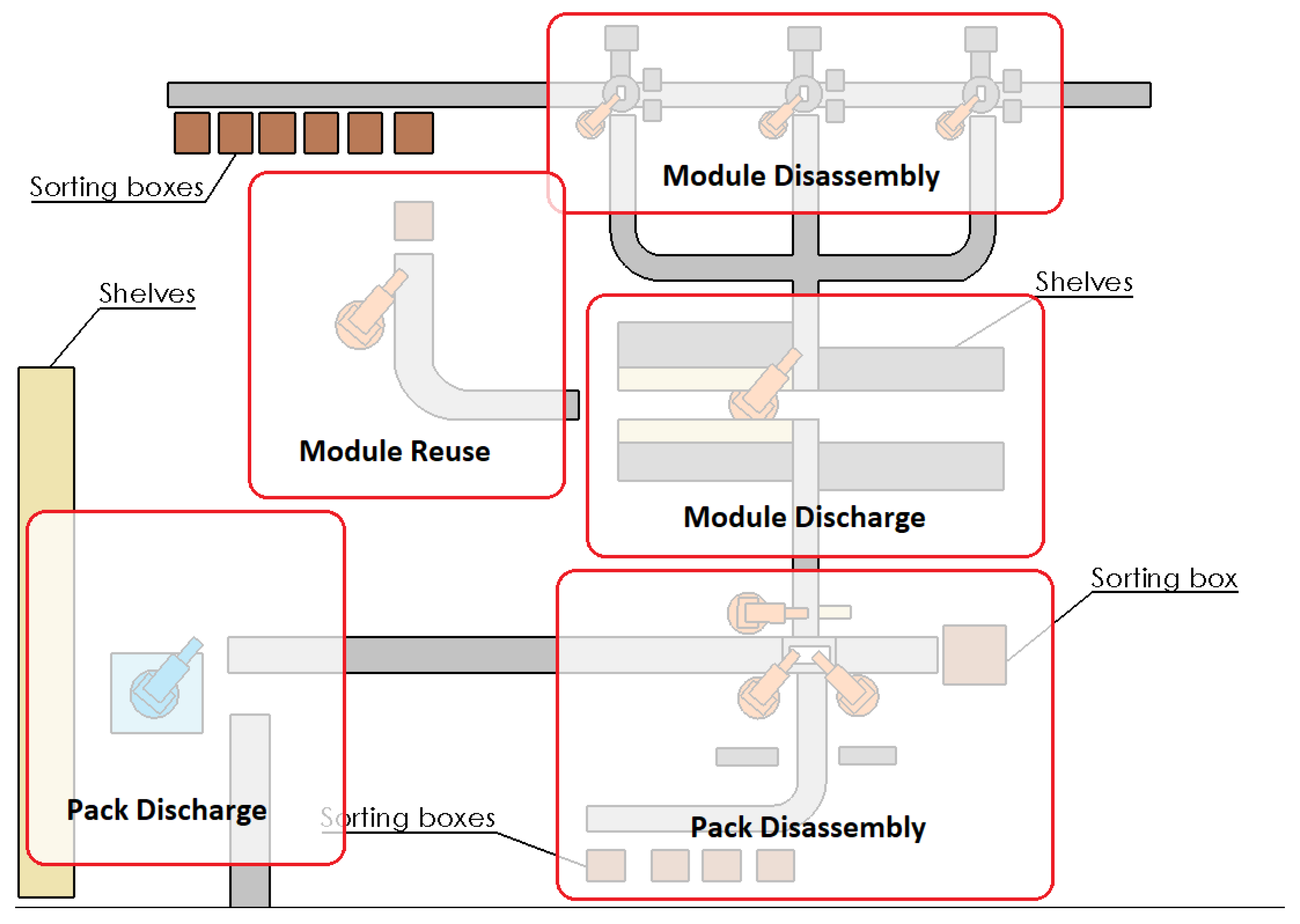
The operations are grouped into five distinct stations, each contributing to a specific segment of the disassembly process, as shown in Figure 2.

2.1.1. Pack Discharge Station

The initial stage focuses on safely discharging battery packs to minimize combustion risks. At the pack discharge station, batteries are carefully discharged to a low cell voltage level between 2.7 V and 3.0 V, ensuring the preservation of reusable modules while preventing full discharge. This process, meticulously managed within a specialized storage area, aims to minimize discharge time while strictly adhering to safety limits, thereby optimizing both the efficiency and safety of the operation. The primary robotic operations at this station are outlined in Table 1, focusing on placement, connection, and transportation of battery packs. This setup addresses the need for floor mobility across potentially extensive shelving areas, ensuring efficient pack handling.

2.1.2. Pack Disassembly Station

The pack disassembly station is designed to maximize the efficiency and accessibility of robotic manipulators. This station, featuring a circular design, strategically positions three (or more) industrial robots, e.g., ABB IRB 4400 (ABB Automation Technologies AB Robotics, Västerås, Sweden), around a centrally located battery pack. This configuration is specifically optimized for diverse disassembly tasks. Each robot can be equipped with specialized tools, tailored to efficiently executing specific functions. For instance, the robot dedicated to unscrewing tasks is equipped with a permanently attached nut runner tool, reflecting the prevalent use of screw connections in various battery packs.
The other two industrial manipulators demonstrate greater versatility, each having access to individual tool-changing stations. This flexibility allows them to adapt to a variety of operations. Post disassembly, two robots are responsible for placing the detached parts onto conveyor leading to the pack station’s sorting system. Larger components, such as the upper and lower housing shells, are directed to another conveyor leading to a collection box. The third robot, positioned adjacently, handles these larger parts.
The station ensures that removed parts are efficiently directed to the corresponding conveyors, leading to the sorting or module discharge stations. The layout ensures minimal collision within the work envelope, maximizing the efficiency of the disassembly process. Further details on the specific disassembly sequences at this station are expounded upon in the case study in Section 3.

2.1.3. Module Characterization and Deep Discharge Station

At this station, modules are characterized and sorted based on their State of Health (SoH). Modules above a certain SoH threshold are directed for reuse, while others undergo deep discharge before proceeding to further disassembly. This station’s robotic tasks, listed in Table 2, revolve around handling and processing the modules, emphasizing the use of a ceiling-mounted robotic manipulator for optimal spatial efficiency.

2.1.4. Module Disassembly Station

The module disassembly station, briefly touched upon in this paper, adopts a design focused on the efficient handling and dismantling of battery modules. The station features a rotation table and specialized manipulators, including a milling robot (e.g., ABB IRB 6660 (ABB Automation Technologies AB Robotics, Västerås, Sweden)) and smaller-payload robots for handling various smaller components (screws, circuit boards, etc.). This setup facilitates the efficient disassembly and sorting of module components.
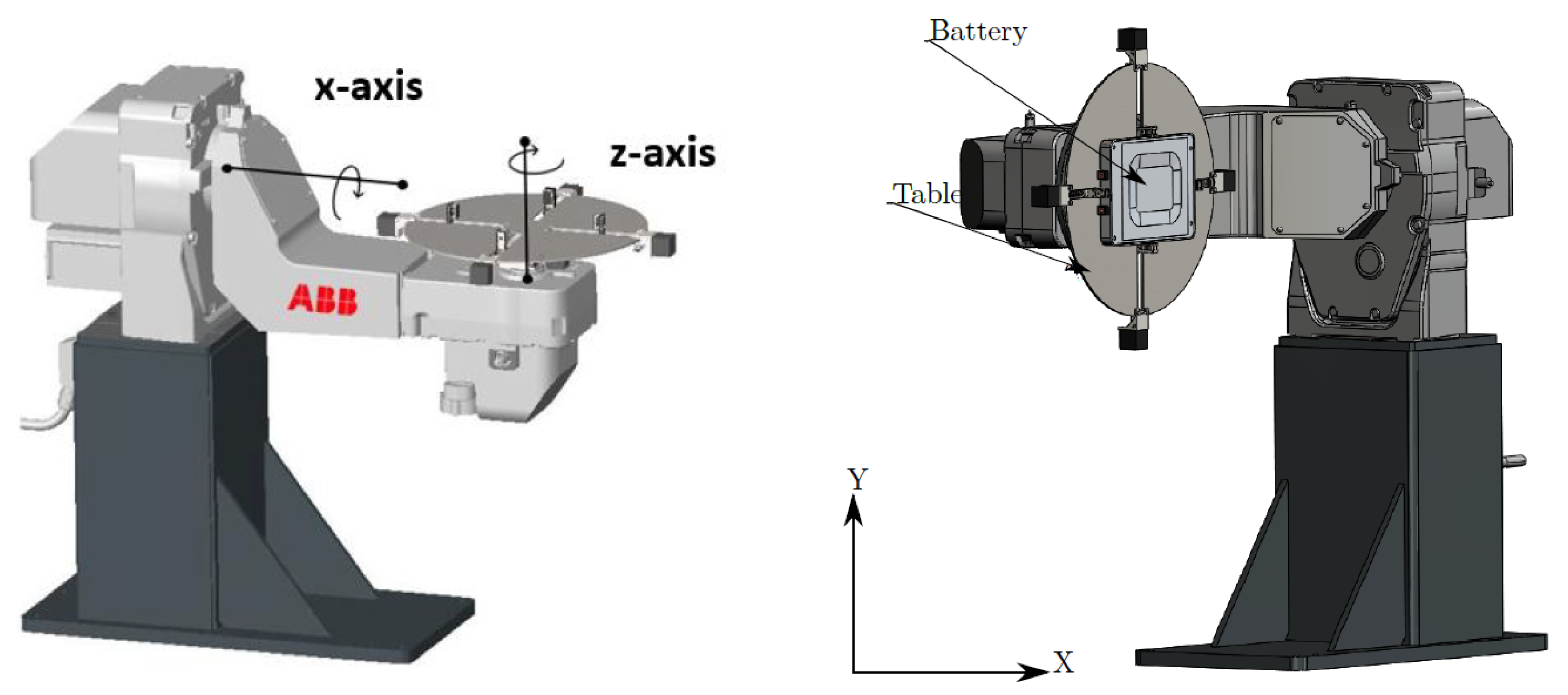
The rotation table is a custom design developed at UiA, and is fixed on an ABB IRBPA positioner which can rotate the whole construction both along the x-axis and z-axis, as demonstrated in Figure 3. With a 180° rotation along the x-axis, all the disconnected cells can fall out from the module to the conveyor beneath leading to the sorting area, with a single movement, rather than being picked out one by one.
Each pack disassembly station is accompanied by multiple module disassembly stations, since a single pack contains multiple modules (e.g., the Nissan leaf 24 kWh battery has 48 modules, while the Passat GTE and Golf GTE batteries have four modules). Additionally, the module disassembly process requires cutting and milling operations, which are time-intensive. Therefore, having only one module station in the line could create a bottleneck.

2.1.5. Sorting System

The sorting system, integral to both pack and module disassembly stations, relies on conveyors to transport removed parts into appropriate sorting boxes. This process can employ hyperspectral imaging technology [22] to identify materials, ensuring accurate separation of plastics, metals, and composites.
The overall design is inherently scalable, allowing for future expansion as demand increases. This overview sets the stage for a more detailed examination on specific disassembly sequences and the time taken for operations and optimized sequences in the subsequent case study in Section 3.

2.2. Simulation Environment

This section presents a method for implementing the demanufacturing line described in Section 2.1 in a Unity3D simulation environment within a virtual industrial warehouse while using the URDF-Importer and ROS-TCP-Connector packages to connect the ROS and Unity3D, whereas all the robotic disassembly operations are animated in Unity3D by using the ROS and MoveIt to plan the trajectories.

2.2.1. 3D Models

The ROS-Industrial repository provides packages for a large variety of robot models and manufacturers, which contain the 3D representations of the robots along with URDF files and MoveIt configurations. These robot models are placed in Unity as game objects which follow a hierarchy of child–parent relationships for the links and joints of their arms. An articulation body component is attached to every link thus forming an articulation body chain. In addition, a controller is added by default to the root of the game object tree, for manual control of the joints.
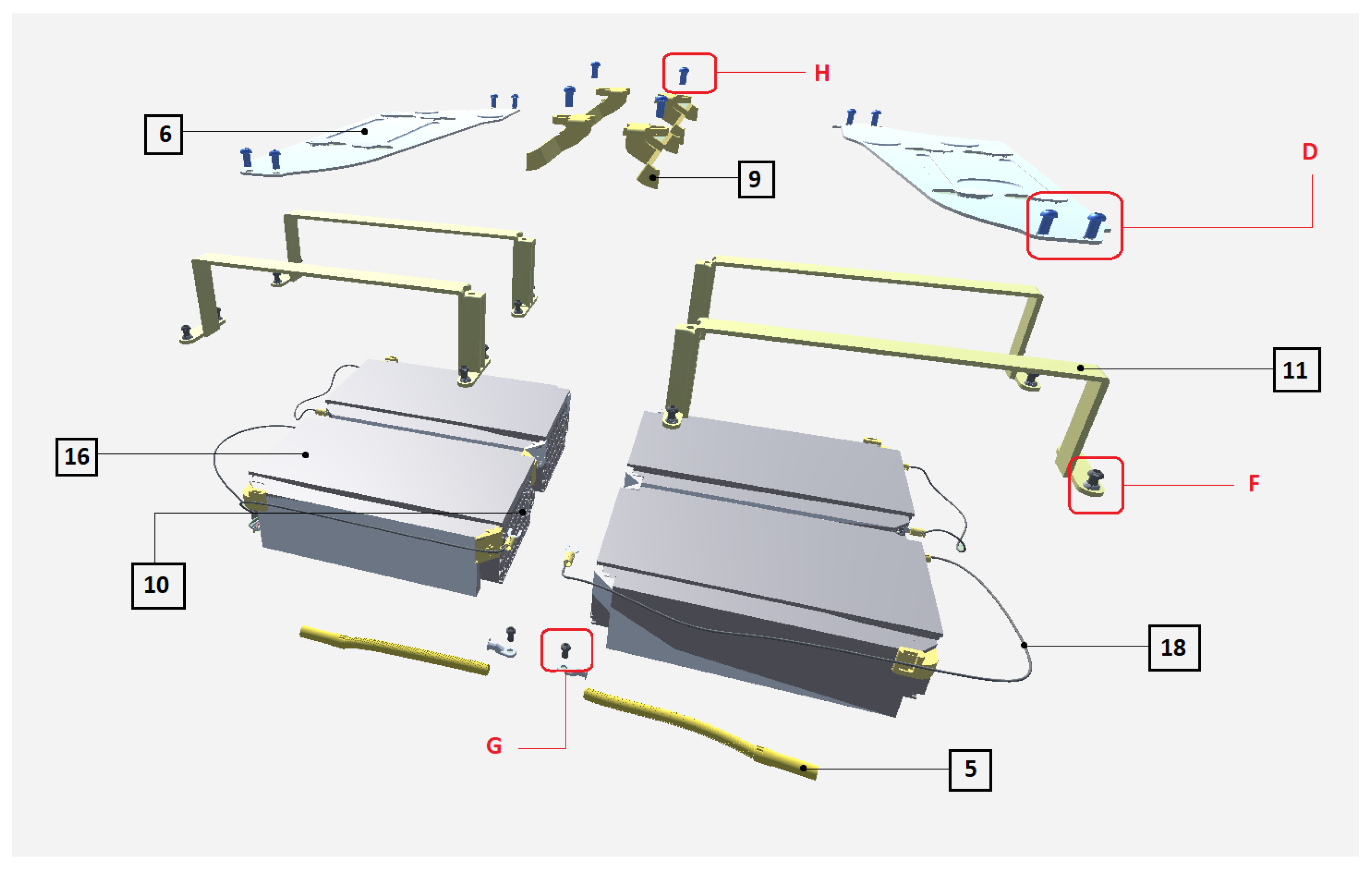
The battery pack assembly model is imported into the simulation in the .fbx format because it maintains the hierarchy of the sub-part assembly that is available in the CAD models. To animate the separation of components in Unity3D, they must be represented by separate game objects. The battery pack model is shown in Figure 4.
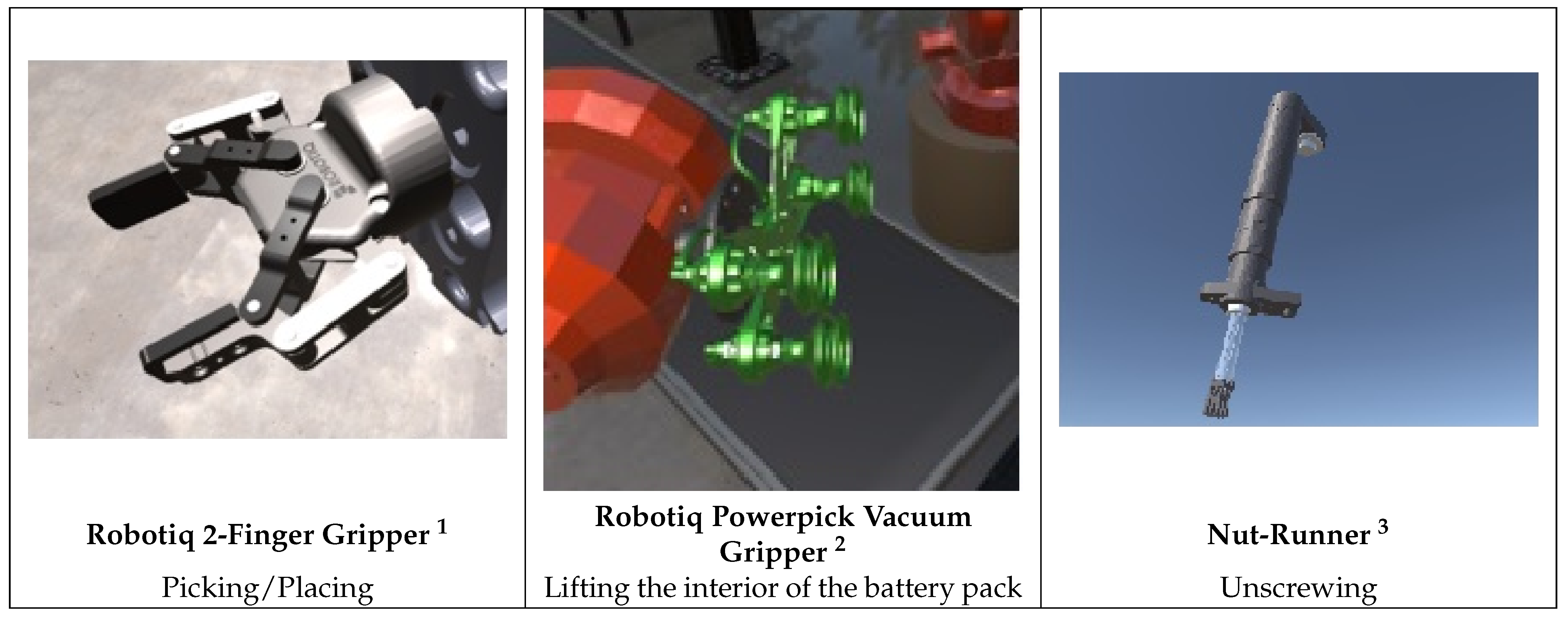
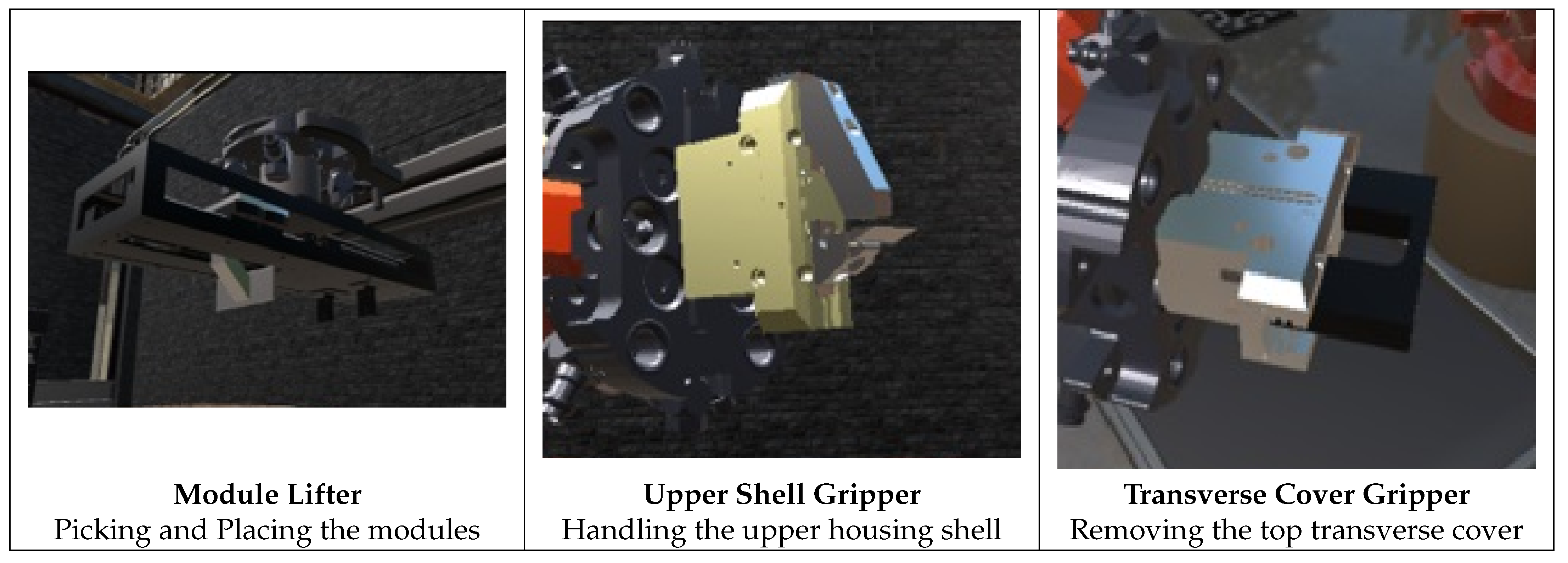
Figure 5 and Figure 6 present a list of the end-effector models used in this work. Each end-effector model is manually configured through Solidworks in a link–joint arrangement, with the type of joints defined, as well as their limits and rotational axis. CAD models are converted to the URDF format using Solidworks-to-URDF exporter and importing URDF files for the end-effectors in Unity is achieved utilizing the URDF-importer package; the former converts models into urdf packages containing all associated files, along with the mesh and collision descriptions, whereas the later imports the urdf to unity. The package generated by the exporter is then configured using the moveit-setup-assistant to ensure that all moving parts and collision checking behaved correctly. The game object of the end-effector is dragged to the tip link of the robot in the Hierarchy window, incorporating it into the articulation chain by “parenting”.

2.2.2. ROS–Unity Communication

This section describes the communication between the ROS (Robot Operating System) and Unity to simulate a robotic arm. The ROS uses MoveIt! to plan trajectories, while Unity executes the resulting motions. Communication is handled through a ROS service: Unity sends a request with current and goal poses, and in return receives the corresponding planned trajectory.
In the ROS, a Python 3.7 script establishes communication, launches individual nodes for stations, and publishes robot descriptions. The core function, “moveit_server()”, connects to the service and triggers planning based on the received poses. The planned trajectories are then sent back to Unity.
In Unity, a C# script “TrajectoryPlanner.cs” handles communication. It retrieve joint positions and targets and sends a request to the ROS. Upon receiving trajectories, it executes them through coroutines that move robots and grippers according to the plan. The communication between Unity3D and ROS is visualized in Figure 7.

2.3. Time Calculation

To assess the operational efficiency of the automated demanufacturing line in the Unity3D simulation, a detailed analysis of the time taken for each operation is conducted. This analysis is crucial for evaluating the viability of the automated solution in real-world scenarios, focusing on disassembly operations’ time efficiency, and identifying potential areas for system improvement.
To ensure precise and consistent time measurements across different simulation runs, two primary time measurement techniques are integrated into the Unity3D simulation scripts:
  • High-Precision Timing with “Stopwatch”: For operations where precision is critical, the “Stopwatch” class from the “System.Diagnostics” namespace is utilized. This method allows for high-resolution timing, which is especially useful for capturing variations in operation lengths within complex or rapid sequences of coroutine functions. The stopwatch is started at the beginning of an operation and stopped upon completion, providing an accurate measure of the elapsed time in real-world seconds.
  • Real-Time Measurement with “Time.time”: For a broader assessment, Unity’s “Time.time” is employed to measure the time from the start until the end of an operation. This simpler method offers a straightforward way to gauge the duration of longer processes, accurately reflecting real time progression.
Each coroutine function, representing sequential operations within the demanufacturing process, is augmented with these timing techniques. This allows for a comprehensive evaluation of the time required for each step of disassembly, from the initial pack disassembly stages to the final extraction of individual cells.

2.4. Optimization of Disassembly Sequence Using Genetic Algorithm

The genetic algorithm (GA) is a powerful approach to optimization, particularly suitable for scenarios where traditional algorithms struggle to find solutions within polynomial time. For the complex multi-robot disassembly process, the scheduling challenge is formulated as a job-shop scheduling problem (JSSP). The complexity arises from the vast number of permutations in assigning interdependent disassembly jobs across homogeneous machines (robots). The immense solution space makes exhaustive search methods by brute force impractical. The GA was selected as a suitable JSSP solver due to its ability to efficiently navigate vast, constrained solution spaces, harness parallel processing potential, and balance global exploration with local exploitation, making it robust for complex, real-world scheduling challenges in demanufacturing. The overall objective is to identify the job sequence that minimizes the total disassembly time while strictly adhering to all precedence constraints.
The problem formulation for the specific case study is detailed in Section 3.

3. Case Study and Results

This section presents an in-depth examination of the demanufacturing process for the Volkswagen Passat GTE Hybrid battery pack. The objective is to demonstrate the efficacy of the proposed demanufacturing line within a meticulously crafted virtual environment. The detailed description of the electric vehicle battery (EVB) pack disassembly is discussed up to the module level, while the complete demanufacturing process extending to the cell level is simulated using a model representing a generic module.
The study includes a comprehensive analysis of the battery pack, its components, and their connections, as well as the precedence diagram guiding the disassembly sequence. Time calculations for each operation are derived from a Unity3D simulation, providing a quantifiable measure of the time efficiency of the automated demanufacturing process compared to conventional manual techniques. These time estimations are then used to optimize the disassembly operation by formulating it as a job shop problem and employing a genetic algorithm to enhance the overall efficiency.

3.1. Description of the Battery Pack and Its Disassembly Process

A detailed structure of the battery pack, leveraging exploded view diagrams to dissect the assembly, is presented in [23]. It offers a look at the structure of both the overall battery pack and its individual modules.
Figure 8 depicts the arrangement and relationship of the various components within the battery pack, providing a clear roadmap for the disassembly process, while a similar approach is taken to detail the module sub-assemblies in Figure 9.
A connection diagram, also known as a precedence diagram [23] or disassembly priority graph [7], schematically represents the sequential relationships among components during the disassembly process. It provides a visual guide for the systematic breakdown of a product into its constituent parts, ensuring an efficient and logically ordered sequence of operations. Such a diagram is crucial to identifying the optimal path for disassembly, as it highlights component dependencies and indicates prerequisites for component removal. By clearly mapping out these relationships, precedence diagrams help minimize the time and effort involved, while maximizing the recovery of valuable materials and components. Ultimately, these diagrams support the development of automated disassembly lines, ensuring that each operation is executed in the proper order to prevent damage to reusable or recyclable parts and to streamline the overall process.
The precedence diagram presented in [23] is slightly modified to allow for the removal of the two top transverse covers (part number 6 in Figure 8)—by horizontal movement to disengage the key holes—once the module assembly has been extracted from the lower housing shell. An updated version is therefore shown in Figure 10, which corresponds to the exploded view in Figure 8 and Figure 9 and the component list in Table 3, from the battery pack to the module level.

3.2. Time Estimation for Demanufacturing

A Unity3D simulation of the demanufacturing line is developed to model and analyze the entire process. Although the details of this simulation are beyond the scope of this paper, it serves as a tool to calculate the operating times for each step of the disassembly process. The time is calculated for individual disassembly operations, as well as for the entire process, as mentioned in Table 4 and Table 5, which corresponds to the list of parts presented in Table 3.
The time taken in Table 4 serves as the baseline for optimization in Section 3.3. This is the time taken by the robot assembly line shown in Figure 2 while following the sequence of operations presented in Figure 10. Thus, the baseline for the unoptimized disassembly sequence is a random feasible sequence of operations using three machines.
The assumptions/simplifications made while calculating the time are mentioned below:
  • Since transportation of live battery packs is not recommended [24,25], the battery packs are first opened at the collection site and high voltage-cables are disconnected. This step takes care of the glue (if any) used to seal the upper housing shell to the lower housing of the battery pack. Hence, the removal of glue/sealant is not simulated.
  • The time needed for the discharging of battery pack to a low voltage and the complete discharge of modules to zero voltage is not considered within the scope of this paper and is conducted simultaneously with the other disassembly operations. Therefore, once the normal operation has started, discharging does not contribute to the overall time calculations of the operations.
  • Detection and identification of battery components is not within the scope of this paper. It is assumed that all parts are identified and localized with acceptable confidence at each step of the operation.
  • Fasteners of modules are not included in the model of the module and hence not simulated. The time is estimated based on screw removal time.
  • The path planning time for robots is not considered as it is less than 1 s and path planning is performed at the same time as other operations.
The total time calculated in Table 4 and Table 5 depicts only the simulated processes and the percentage time is calculated on the basis of total time of all operations i.e., 790.7 s. The detection and identification of the battery pack components are not simulated and hence not included in the time calculations. However, Refs. [14,26,27] present a robust framework for a multiple-camera system which aligns with the industrial solutions for the detection and identification of complex objects e.g., battery packs. This time depends on the camera used, number of images/cameras utilized, capture of RGB images or point clouds, the method for the fusion of results, and the detection algorithms.

3.3. Genetic Algorithm Optimization

The data used for the optimization is derived directly from the simulation environment.
  • Jobs (J): 25 disassembly operations (Jobs 0 through 24), representing component and screw removal.
  • Processing Time (T): The time required for the machine to complete a job, as calculated and validated by the Unity–ROS simulation (Table 6).
  • Chromosomes: The chromosome (solution) is represented by two arrays:
    • Job sequence: The GA uses an order-based representation (permutation), where a chromosome is a list of job indices representing the order in which all 25 jobs are processed.
    • Machine assignment: The machine dedicated to each job. For this study, the machine assignment is fixed and deterministic, based on a predetermined allocation array rather than being evolved by the algorithm.
  • Constraints (C): The component interconnections are defined by the Dependency Matrix (Figure 11), which serves as the core set of precedence constraints.
  • Fitness Function (F): The goal is to minimize the total completion time, or Makespan, which is calculated by the internal scheduler using the job sequence and the fixed machine assignments. The fitness function is structured to maximize the inverse of the makespan.
From Table 3, the removal of components 1 to 16 is renamed to jobs 0 to 15, and the removal of screws A to I is renamed to jobs 16 to 24 for the formulation of the dependency matrix. The dependency matrix mentioned in the Figure 11 is another way of showing the interconnection of the various components and is formulated from the precedence diagram shown in the Figure 10. Renaming the removal operations as sequential jobs (0 through 24) makes it easier to use for genetic algorithm programming. Since, the operations are renamed sequentially, the time for operations (jobs) can be rewritten as in Table 6. Table 6 is based on the time calculated in Table 4 and Table 5.
The reasoning behind taking the operation time to be zero for operations that are not simulated is to simplify the comparison with the times mentioned in Table 4 and Table 5.
The precedence or dependency matrix, depicted in Figure 11, is fundamental to ensuring the feasibility of any solution. It defines the strict order in which jobs must be carried out, where a ‘1’ signifies that a job depends on the prior completion of another. The GA uses this matrix during the initial population generation and throughout the evolutionary process, particularly during crossover and mutation operations and before mutation, respectively, to guarantee that all generated solutions represent valid and executable disassembly sequences. This prevents the algorithm from wasting computational resources on impossible scenarios and guides it towards promising areas of the solution space. In essence, the genetic algorithm’s objective is to identify the sequence of disassembly jobs that minimizes the overall disassembly time while strictly adhering to all precedence constraints. The precedence matrix acts as a feasibility filter, ensuring only valid solutions are considered, while the time information provides the quantitative measure for evaluating and comparing the quality of these valid solutions. The tight integration of these two data sources enables the GA to effectively navigate the vast solution space and ultimately converge on an optimal or near-optimal disassembly plan.
The parameters used for the GA are:
  • Generations: 20 generations.
  • Population: 6 solutions.
  • Selection Method: Softmax transformation to prioritize parents with shorter makespans for reproduction.
  • Crossover: The crossover operation employs a modified order-based crossover tailored for sequenced jobs. In this process, elements of the two selected parent sequences are combined to generate two offspring sequences while maintaining job uniqueness. To select contributions, each job element in the parental sequence is assigned a random selection rate (1 or 2). If the rate is 1, the corresponding element from Parent 1 is considered; if the rate is 2, the element from Parent 2 is considered. To prevent invalid solutions due to job duplication, if a selected element is already present in the offspring sequence, that element is systematically removed from the available pool of the parent from which it was selected, guaranteeing that each child solution contains unique genetic material.
  • Mutation: A sophisticated mutation function was designed to refine the job sequence by integrating precedence awareness. This process involves randomly selecting two jobs from the sequence, evaluating their precedence relationships, and if both jobs share identical precedence constraints, the one with the later processing time is prioritized and inserted ahead of the one with the earlier processing time. This design ensures that the mutation respects the precedence constraints inherent in the job sequence, allowing the rearrangement of jobs only when resource (machine) allocation is the sole limiting factor.
This process is carried out while considering two, three, and then four robots (machines) formulating the optimization as a job shop problem [19].

Results of GA Optimization

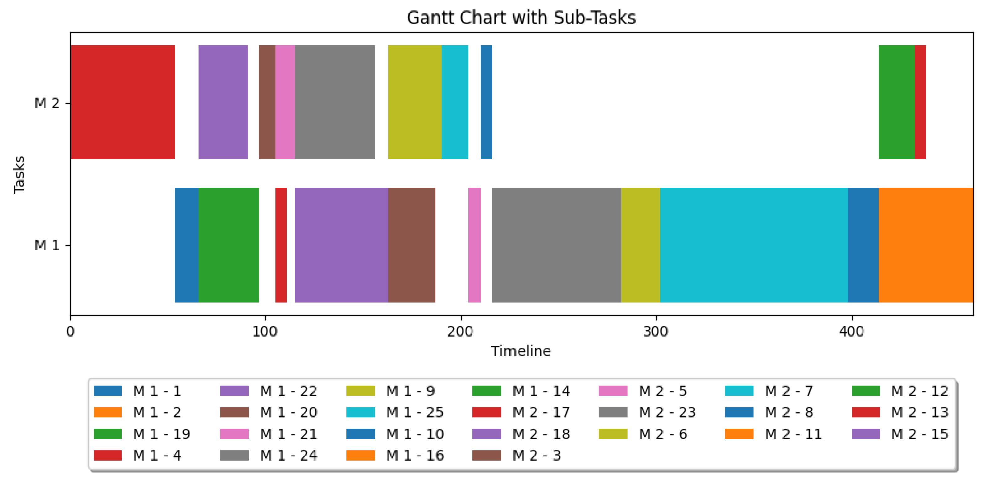
Figure 12 shows the result of GA optimization by Gantt chart for two homogeneous machines after 20 generations. The chart uses different colored blocks to represent various disassembling jobs, which is also explained in the legend. The x-axis indicates the processing time in seconds, while the y-axis displays the two machines, which are homogeneous. In total, it takes 462 s to complete all the jobs.
Figure 13a underscores the potential of the GA to optimize processing times within the system for two homogeneous machines. The x-axis represents the processing time of the different solutions, while the y-axis represents the number of solutions. The yellow bars depict the solutions optimized with the GA, whereas the blue bars represent the solutions without the GA (random search for feasible solutions). By narrowing the range of processing duration, the GA demonstrates its ability to effectively arrange the execution of jobs, thereby enhancing overall system performance.
In Figure 13b, the probability density function comparison plot illustrates the distribution of processing times under two distinct scenarios: “Processing time without GA” (blue line) and “Processing time with GA” (yellow line). The x-axis denotes the processing time in seconds, ranging from the minimum to the maximum observed values across both datasets. Concurrently, the y-axis represents the probability density, providing insight into the likelihood of encountering specific processing time values within each dataset. The plot features two lines corresponding to the PDF estimation for each dataset, allowing for a visual comparison between their respective distributions.
Figure 14 illustrates the allocation and scheduling of tasks across three homogeneous machines. The total processing time is 456 s after 20 generations.
Figure 15a presents histograms depicting the distribution of solutions based on processing time. It is evident that the majority of solutions using the genetic algorithm (yellow) have processing times under 460 s, which is shorter than the processing times without the genetic algorithm (blue). Figure 15b displays the probability density function comparison plot for three homogeneous machines.
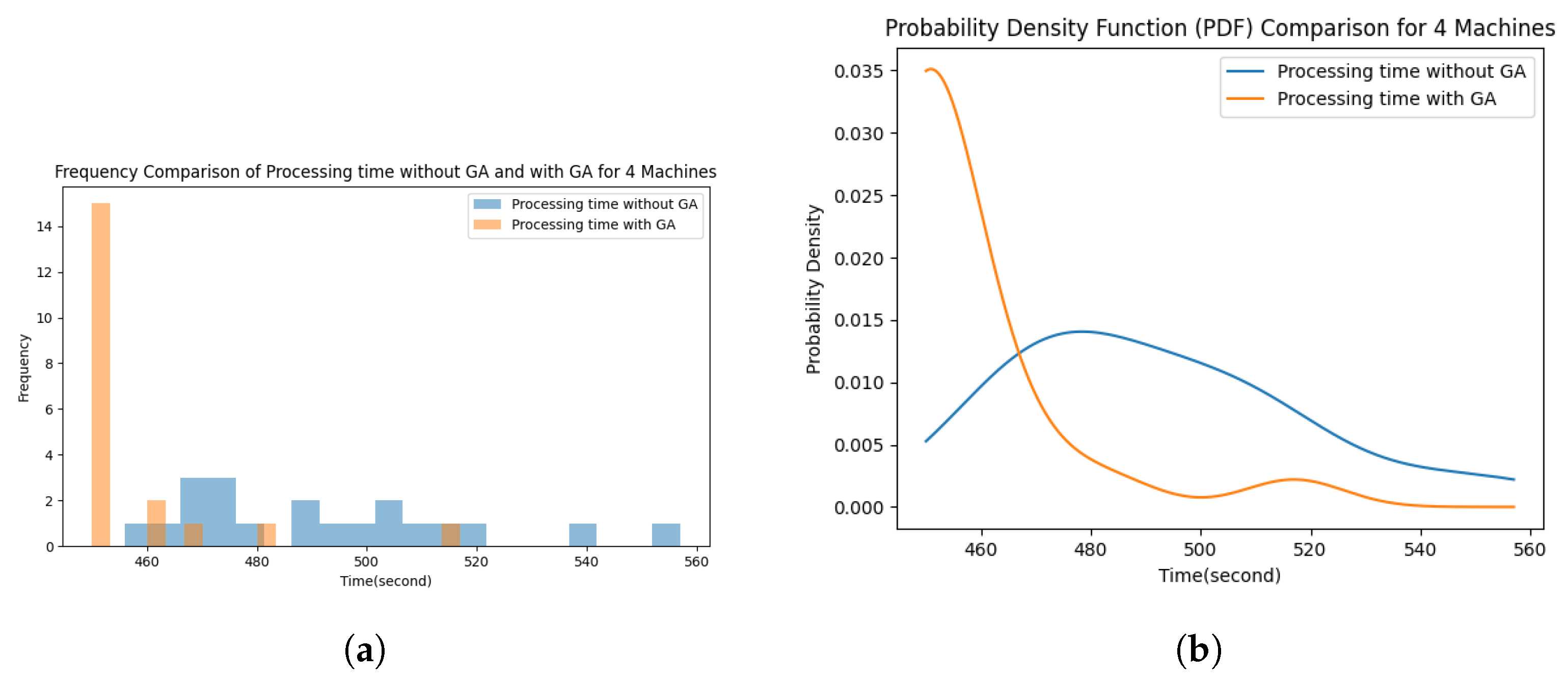
The best result from GA optimization for four homogeneous machines is shown in Figure 16. The total processing time is 450 s after 20 generations.
Similarly, the histogram of the solutions is given in Figure 17a. Figure 17b displays the probability density function comparison plot for four homogeneous machines.

4. Discussions

Several insights emerge, showcasing the potential efficiencies and innovations that automated disassembly lines can offer in the context of end-of-life EV battery recycling, by analyzing the results obtained from the simulation of the demanufacturing process for the Volkswagen Passat GTE Hybrid Li-ion battery pack.
Description of battery pack and its disassembly process: The incorporation of precedence diagrams in planning the disassembly sequence greatly enhanced the overall process flow. By establishing a logical order for component removal, these diagrams ensure that the process proceeds in a controlled manner, minimizing the risk of damaging valuable, recyclable, or reusable parts. This structured approach not only preserves material integrity but also increases the overall efficiency of the recycling process.
The transition to a fully automated demanufacturing line, as depicted through the Unity 3D simulated environment, presents a significant step forward in addressing the complexities associated with the disassembly of electric vehicle batteries (EVBs). This simulation not only showcased the feasibility of automating the disassembly process but also illuminated the potential time savings compared to traditional manual methods. The breakdown of the battery pack into its constituent modules and further into individual cells highlighted the precision and efficiency achievable through automation.
Time estimation for demanufacturing: Central to the discussion is the time efficiency analysis, which revealed that automated processes could markedly reduce the time required for disassembly. The detailed time estimation provided in Table 4 serves as a comparative benchmark against manual disassembly techniques, underscoring the potential for significant improvements in both speed and safety. These findings suggest that by embracing automated demanufacturing lines, the recycling industry could enhance throughput while minimizing human exposure to potential hazards associated with battery disassembly.
The unscrewing task takes up a total of six minutes (360 s) which amounts to 46% of the total time for disassembling the battery pack into cells. The second most time consuming task is cutting open the module to get to the cells, which takes up 2.5 min (150 s) and amounts to 19% of the total time taken. By focusing on the optimization of these two operations, the time for disassembly can be reduced, making the entire demanufacturing process more efficient and profitable.
Optimization: The time for the initial unoptimized sequence shown in Table 4 was 600 s, which was reduced to 450 s after GA optimization as shown in Figure 16. This result showcases an improvement of 25% between unoptimized and optimized time for pack-to-module disassembly. The difference in performance is very small when utilizing two, three, or four robots due to the presence of fewer parallel operations in the precedence diagram in Figure 10. For a more complex battery pack with multiple parallel operations, this difference in performance will be higher, and the full optimization capabilities of the genetic algorithm will be utilized. This is evident in Figure 14 and Figure 16 where a considerable number of white spaces is present. These white spaces show that the robots are idle during this time and waiting for other robots to finish their operations before continuing.
Table 7 shows the best result from GA optimization after 20 generations. The first row represents the different numbers of homogeneous machines, these being two, three, and four, respectively. The second row represents the results from the GA in seconds, and the third row represents the percentage comparison of results with respect to two machines. Compared to the two machine result, the three machine result is 1.3% better, and the four machine result is 2.6% better.
Challenges: In the simulation, robot motions were generated using Moveit, which defaults to the rapidly exploring random tree (RRT) planner which, while versatile, often produced inefficient trajectories, such as unnecessary 360-degree rotations, leading to potential collisions. By switching from RRT to the transition-based RRT (TRRT) planner, a variant that integrates stochastic optimization for more efficient paths, motion planning significantly improved. This adjustment resulted in direct and collision-free trajectories, showcasing the impact of planner choice on achieving optimal robot motion in simulations. This leads to the robot taking a slightly longer time for all operations even if this time difference is considered negligible for this case study.
A more salient point of discussion revolves around the inherent challenges and assumptions of the simulation model, which impacts real-world applicability. The process simplifications made—for instance, not simulating the removal of adhesives or the initial discharging steps—mean the simulated times represent a lower-bound theoretical minimum. In a physical setting, the integration of these pre-dismantling steps would necessitate dedicated stations, specialized tools (e.g., thermal or chemical), and would introduce a significant time overhead, potentially adding several minutes to the total cycle time per battery pack.
Additionally, the model currently omits fixed auxiliary time factors, like tool change time and component detection time, that would impact the final system design and performance. Based on industrial robotic standards, each required tool change is a fixed overhead, conservatively estimated to take between 15 and 30 s. In simulation, it was calculated to be 5 s due to the simplified design of the tool changing station and the absence of the force/torque calculations required during the tool change operation. As the complete dismantling procedure requires multiple tools, this factor could collectively add upwards of 1.5 to 3 min to the overall process duration, significantly affecting the true system throughput.
The component detection time is a combination of robot movements, image acquisitions, and image processing to arrive at the location of individual components in 3D space. Ignoring this omits the essential latency introduced by vision system processing and assumes perfect knowledge of component location. Integrating detection necessitates robust sensor hardware, processing units, and control logic, adding complexity to the overall system design and impacts task success rates.
Addressing these modeling limitations through future studies could provide deeper insights into the nuances of battery pack demanufacturing, resulting in a more refined and industrially applicable automation strategy.

5. Conclusions

This study successfully demonstrates the development of a high-fidelity, multi-robot robotic cell simulation for the complete demanufacturing of EV lithium-ion battery packs. The simulation utilized a design implemented within a ROS-powered Unity3D environment that provides a virtual, yet realistic, industrial solution encompassing all necessary operations from discharge to cell extraction. This environment validates the feasibility of automating the disassembly process and serves as a safe, cost-effective platform for testing new process designs and system complexities. The design specifically supports multi-robot simulation and leaves significant room for expansion and the incorporation of future research developments.
Our core contribution lies in three areas: first, the validation of Unity–ROS integration for complex multi-robot trajectory planning; second, the utilization of a simulation for the real-time calculation of operation time for each disassembly operation; and thirdly, the demonstration of genetic algorithm (GA) optimization to minimize cycle time. The optimization results showed a significant 25% reduction in assembly time for the pack-to-module stage compared to unoptimized sequences. Furthermore, the time analysis explicitly identified unscrewing and cutting tasks as the primary bottlenecks, highlighting specific operations where targeted efficiency improvements will yield the greatest overall process benefits.
This simulation collectively highlights the benefits of automated demanufacturing processes and underscores the potential for automated lines to efficiently support the circular economy by significantly reducing e-waste and enabling resource conservation through reliable component recovery.
Future work: Moving forward, research will focus on advancing the fidelity of the simulation environment and leveraging optimization findings. Key next steps include incorporating solutions for real-time collision avoidance, optimizing simultaneous trajectory planning to better utilize multi-robot systems, and addressing the modeling simplifications (such as tool change time and component detection latency) to align the simulation closer with real-world industrial throughput.
The oversimplified current robot animation sequences call for a detailed analysis and optimal trajectory planning to boost efficiency and cut down cycle times. Furthermore, surpassing Moveit’s limitations in planning and executing multiple trajectories simultaneously is an area ripe for development. Initial strategies include planning all trajectories from the start and managing their sequential execution within Unity, with additional research required on handling concurrent planning requests, possibly through ROS2. To achieve more precise trajectory planning, future improvements will incorporate the publishing of surrounding objects into Moveit’s planning scene and the development of an online collision avoidance system. Implementing real-time collision avoidance will enable the system to conduct various operations concurrently, such as tool changing and removing screws while also removing smaller parts like cables and BJBs.
The current method of catching screws involves the robot moving to and from the bucket, accounting for approximately 50% of the total unscrewing time. Eliminating this motion will expedite the process. Therefore, a specially designed unscrewing tool with a bucket attached to the nut runner to catch the removed screws will significantly reduce the time dedicated to the unscrewing task.
The number of robots can be reduced or increased by making use of an efficient tool changing solution. The results in Section 3.3 do not consider tool changing operations (jobs) or the time taken for tool changes. Since a number of different tools are available to perform different tasks, a tool changing matrix will be developed which can offer crucial insights on optimization of disassembly sequence and impact the time taken for the complete operation.

Author Contributions

Conceptualization, M.C., I.T. and L.J.; methodology, M.T.B.; software, M.T.B. and D.S.T.; validation, M.T.B., M.C., I.T. and L.J.; formal analysis, M.T.B. and D.S.T.; investigation, M.T.B. and D.S.T.; resources, I.T., L.J. and M.C.; data curation, M.T.B.; writing—original draft preparation, M.T.B. and M.C.; writing—review and editing, M.T.B., M.C., D.S.T., I.T. and L.J.; visualization, M.C., I.T., M.T.B. and D.S.T.; supervision, I.T., M.C. and L.J.; funding acquisition, I.T., M.C. and L.J. All authors have read and agreed to the published version of the manuscript.

Funding

Funded by the European Union under Grant Agreement No 101069685. Views and opinions expressed are, however, those of the author(s) only and do not necessarily reflect those of the European Union or the European Climate, Infrastructure, and Environment Executive Agency (CINEA). Neither the European Union nor the granting authority can be held responsible for them.

Data Availability Statement

The data presented in this study are available on request from the corresponding author due to ongoing research on the data as well as the size of raw files for the simulator.

Acknowledgments

The authors acknowledge the contributions of bachelor student projects towards creating the 3D models of the battery pack, tools, end-effectors, and the simulation environment. During the preparation of this manuscript/study, the author(s) used Grammarly Pro and Copilot Chat for Microsoft Edge to provide feedback for improving grammar, language, and the conciseness of the text. The authors have reviewed and edited the output and take full responsibility for the content of this publication.

Conflicts of Interest

The authors declare no conflicts of interest.

Abbreviations

The following abbreviations are used in this manuscript:
EVElectric Vehicle
3DThree Dimensional
ROSRobot Operating System
VRVirtual Reality
URDFUnified Robotics Description Format
HDRPHigh-Definition Rendering Pipeline
BEVBattery Electric Vehicle
GAGenetric Algorithm
LIBLithium-Ion Battery
SoHState of Health
VVolts
ABBAsea Brown Boveri
IRBIndutrial Robot
UR5Universal Robot 5
UiAUniversity of Agder
IRBPAIndutrial Robot Positioner A
kWhKilowatt-hour
GTEGran Turismo Electric
TCPTransmission Control Protocol
CADComputer Aided Design
FBXFilmBox
JSSPJob Shop Scheduling Problem
EVBElectric Vehicle Battery
BMCBattery Management Controller
BJBBattery Junction Box
RGBRed Green Blue
NANot Applicable
RRTRapidly Exploring Random Tree
TRRTTransition-Based Rapidly Exploring Random Tree

References

  1. Hoener, S.; Mellert, F.T. Offline Programming of Industrial Robots. In Toward the Factory of the Future; Bullinger, H.J., Warnecke, H.J., Eds.; Springer: Berlin/Heidelberg, Germany, 1985; pp. 597–602. [Google Scholar]
  2. Coronado, E.; Itadera, S.; Ramirez-Alpizar, I.G. Integrating Virtual, Mixed, and Augmented Reality to Human–Robot Interaction Applications Using Game Engines: A Brief Review of Accessible Software Tools and Frameworks. Appl. Sci. 2023, 13, 1292. [Google Scholar] [CrossRef]
  3. Murhij, Y.; Serebrenny, V. An application to simulate and control industrial robot in virtual reality environment integrated with IR stereo camera sensor. IFAC-PapersOnLine 2019, 52, 203–207. [Google Scholar] [CrossRef]
  4. Togias, T.; Gkournelos, C.; Angelakis, P.; Michalos, G.; Makris, S. Virtual reality environment for industrial robot control and path design. Procedia CIRP 2021, 100, 133–138. [Google Scholar] [CrossRef]
  5. Konrad, A. Simulation of Mobile Robots with Unity and Ros: A Case-Study and a Comparison with Gazebo. Master’s Thesis, University West, Trollhättan, Sweden, 2019. [Google Scholar]
  6. Herrmann, C.; Raatz, A.; Andrew, S.; Schmitt, J. Scenario-based development of disassembly systems for automotive lithium ion battery systems. Adv. Mater. Res. 2014, 907, 391–401. [Google Scholar] [CrossRef]
  7. Wegener, K.; Andrew, S.; Raatz, A.; Dröder, K.; Herrmann, C. Disassembly of Electric Vehicle Batteries Using the Example of the Audi Q5 Hybrid System. Procedia CIRP 2014, 23, 155–160. [Google Scholar] [CrossRef]
  8. Wegener, K.; Chen, W.H.; Dietrich, F.; Dröder, K.; Kara, S. Robot Assisted Disassembly for the Recycling of Electric Vehicle Batteries. Procedia CIRP 2015, 29, 716–721. [Google Scholar] [CrossRef]
  9. Tan, W.J.; Chin, C.M.M.; Garg, A.; Gao, L. A hybrid disassembly framework for disassembly of electric vehicle batteries. Int. J. Energy Res. 2021, 45, 8073–8082. [Google Scholar] [CrossRef]
  10. Xiao, J.; Jiang, C.; Wang, B. A Review on Dynamic Recycling of Electric Vehicle Battery: Disassembly and Echelon Utilization. Batteries 2023, 9, 57. [Google Scholar] [CrossRef]
  11. Yin, H.; Xiao, J.; Wang, G. Human-Robot Collaboration Re-Manufacturing for Uncertain Disassembly in Retired Battery Recycling. In Proceedings of the 2022 5th World Conference on Mechanical Engineering and Intelligent Manufacturing (WCMEIM), Ma’anshan, China, 18–20 November 2022; pp. 595–598. [Google Scholar] [CrossRef]
  12. Li, J.; Barwood, M.; Rahimifard, S. Robotic disassembly for increased recovery of strategically important materials from electrical vehicles. Robot. Comput.-Integr. Manuf. 2018, 50, 203–212. [Google Scholar] [CrossRef]
  13. Baazouzi, S.; Rist, F.P.; Weeber, M.; Birke, K.P. Optimization of Disassembly Strategies for Electric Vehicle Batteries. Batteries 2021, 7, 74. [Google Scholar] [CrossRef]
  14. Choux, M.; Marti Bigorra, E.; Tyapin, I. Task Planner for Robotic Disassembly of Electric Vehicle Battery Pack. Metals 2021, 11, 387. [Google Scholar] [CrossRef]
  15. Blankemeyer, S.; Wiens, D.; Wiese, T.; Raatz, A.; Kara, S. Investigation of the potential for an automated disassembly process of BEV batteries. Procedia CIRP 2021, 98, 559–564. [Google Scholar] [CrossRef]
  16. Xiao, J.; Terzi, S.; Macchi, M.; Rosa, P. Intelligent disassembly system for end-of-life product using human robot collaboration on a digital twin platform. Procedia CIRP 2025, 136, 654–658. [Google Scholar] [CrossRef]
  17. Xiao, J.; Huang, K.; Terzi, S.; Bandinelli, R. Towards uncertainty of End-of-Use product recycling: A general screw connection-oriented disassembly analysis. Int. J. Prod. Res. 2025, 1–24. [Google Scholar] [CrossRef]
  18. Xiao, J.; Anwer, N.; Li, W.; Eynard, B.; Zheng, C. Dynamic Bayesian network-based disassembly sequencing optimization for electric vehicle battery. CIRP J. Manuf. Sci. Technol. 2022, 38, 824–835. [Google Scholar] [CrossRef]
  19. Ren, Y.; Zhang, C.; Zhao, F.; Xiao, H.; Tian, G. An asynchronous parallel disassembly planning based on genetic algorithm. Eur. J. Oper. Res. 2018, 269, 647–660. [Google Scholar] [CrossRef]
  20. Mattfeld, D.; Bierwirth, C. An efficient genetic algorithm for job shop scheduling with tardiness objectives. Eur. J. Oper. Res. 2004, 155, 616–630. [Google Scholar] [CrossRef]
  21. Iklassov, Z.; Medvedev, D.; Solozabal Ochoa de Retana, R.; Takac, M. On the Study of Curriculum Learning for Inferring Dispatching Policies on the Job Shop Scheduling. In Proceedings of the IJCAI-23: Thirty-Second International Joint Conference on Artificial Intelligence, Macao, China, 19–25 August 2023; pp. 5350–5358. [Google Scholar] [CrossRef]
  22. Picon, A.; Ghita, O.; Iriondo, P.M.; Bereciartua, A.; Whelan, P.F. Automation of waste recycling using hyperspectral image analysis. In Proceedings of the 2010 IEEE 15th Conference on Emerging Technologies and Factory Automation (ETFA 2010), Bilbao, Spain, 13–16 September 2010; pp. 1–4. [Google Scholar] [CrossRef]
  23. Alfaro-Algaba, M.; Ramirez, F.J. Techno-economic and environmental disassembly planning of lithium-ion electric vehicle battery packs for remanufacturing. Resour. Conserv. Recycl. 2020, 154, 104461. [Google Scholar] [CrossRef]
  24. United Nations. Committee of Experts on the Transport of Dangerous Goods. In Recommendations on the Transport of Dangerous Goods: Model Regulations; United Nations Publications: New York, NY, USA, 2009; Volume 1. [Google Scholar]
  25. International Air Transport Association (IATA). Dangerous Goods Regulations (DGR), 65th ed.; Guidance for the Transport of Lithium Batteries and Other Hazardous Materials by Air; IATA: Montreal, QC, Canada, 2024. [Google Scholar]
  26. Bilal, M.T.; Tyapin, I.; Choux, M.M.H. Enhancing object localization accuracy by using multiple camera viewpoints for disassembly systems. In Proceedings of the IECON 2022–48th Annual Conference of the IEEE Industrial Electronics Society, Brussels, Belgium, 17–20 October 2022; pp. 1–6. [Google Scholar]
  27. Bilal, M.T.; Tyapin, I.; Choux, M.M.H. Fusion of Multiview Images for EV Battery Disassembly. In Proceedings of the 2023 11th International Conference on Control, Mechatronics and Automation (ICCMA), Grimstad, Norway, 1–3 November 2023; pp. 19–24. [Google Scholar]
Figure 1. Task Overview of Operations within the Demanufacturing Line.
Robotics 14 00156 g001
Figure 2. Task Overview of Stations within the Disassembly Line.
Robotics 14 00156 g002
Figure 3. Demonstration of table at the idle position (left) and at a 90° position (right) loaded with a battery module.
Robotics 14 00156 g003
Figure 4. 3D model for the Volkswagen Passat GTE Hybrid battery pack.
Robotics 14 00156 g004
Figure 5. List of commercially available end-effectors used in the simulation. The images of end-effectors are taken by importing the 3D models into the Unity3D simulation. The end-effectors are commercially available at the following links: 1 https://robotiq.com/products/adaptive-grippers#Two-Finger-Gripper (accessed on 5 October 2025). 2 https://robotiq.com/products/vacuum-grippers#PowerPick (accessed on 5 October 2025). 3 https://files.desouttertools.com/documentation-files/MC38-10_Manual_6159935520-02.pdf (accessed on 5 October 2025).
Robotics 14 00156 g005
Figure 6. List of end-effectors, designed at UiA, used in the simulation.
Robotics 14 00156 g006
Figure 7. The Unity and ROS communication system for trajectory planning and visualization.
Robotics 14 00156 g007
Figure 8. Exploded View of the Battery Pack.
Robotics 14 00156 g008
Figure 9. Exploded view of module assembly.
Robotics 14 00156 g009
Figure 10. Precedence diagram of the selected EV LIB pack.
Robotics 14 00156 g010
Figure 11. Dependency Matrix.
Robotics 14 00156 g011
Figure 12. The solution from GA for two homogeneous machines.
Robotics 14 00156 g012
Figure 13. GA Optimization for two homogeneous machines. (a) Frequency comparison of processing time without and with GA. (b) Probability density function comparison.
Robotics 14 00156 g013
Figure 14. The solution from GA for three homogeneous machines.
Robotics 14 00156 g014
Figure 15. GA Optimization for three homogeneous machines. (a) Frequency comparison of processing times without and with GA. (b) Probability Density Function Comparison.
Robotics 14 00156 g015
Figure 16. The solution from the GA for four homogeneous machines.
Robotics 14 00156 g016
Figure 17. GA Optimization for four homogeneous machines. (a) Frequency comparison of processing time without and with GA. (b) Probability density function comparison.
Robotics 14 00156 g017
Table 1. Task Overview of Operations within the Pack Discharge Station.
SequenceTask
I.Placement of the packs onto the shelves.
II.Connecting the packs to the discharging system.
III.Disconnecting the packs.
IV.Transport to the pack disassembly location.
Table 2. Task Overview of Operations within the Module Discharge Area.
SequenceTask
I.Pick and place module on the testing worktable.
II.Pick and place tested modules either on a conveyor or on a discharging shelve.
III.Connect and disconnect module to the discharging system.
IV.Pick and place the discharged modules on a conveyor.
Table 3. Components of the Volkswagen Passat GTE Hybrid Li-ion battery pack.
Ref.DenominationQty.
1/AUpper housing shell/screw1/18
2Upper insulator1
3Plug-in cable between BJB and BMC1
4/CBattery junction box (BJB)/screw1/6
5/BHigh voltage cables and connectors/anchor1/6
6/DTop transverse cover/screw2/6
7Plug-in cable BMC1
8/EBattery management controller (BMC)1/1
9/HModule connector/screw4/12
10/ISide module junction/screw16/16
11Fastener of module32
12/FCooling plate/screw4/16
13/GCooling pipe/screw2/7
14Lower insulation1
15Lower housing shell1
16Module8
Table 4. Time taken for each simulated operation in disassembly of pack to module.
StationOperationSimulationPercentage
(Number of Components)Time (s)Time
Pack
Disassembly
Station
Upper housing screws (18) *546.8
Tool change **50.6
Upper housing shell121.5
Screws of BJB (6)313.9
Remove connectors (2)81.0
Remove anchors/cut ties (6)25 3.2
Remove BJB60.8
Remove cables (2)101.3
Unscrew transverse cover (8)243.0
Unscrew cooling plates (16)48 6.1
Unscrew cooling pipes (7)41 ‡‡5.2
Remove subassembly19.22.4
Remove plates (2)273.4
Remove BMC, cables, connectors,8010.1
screws (4)
Remove modules (8)486.1
Module connector, side module66 8.3
junction screws (22)
Module Fasteners (32)96 12.1
Total Time 600.2 (10:00)
* Six seconds per two screws simultaneously (two robots). ** Tool change can be performed simultaneously with previous task to save time. Estimated based on internal projects, not simulated. Estimated time for 16 screws based on simulation of 8 screws. ‡‡ Estimated time for 7 screws based on simulation of 3 screws.
Table 5. Time taken for each simulated operation in disassembly of module to cells.
StationOperationSimulationPercentage
(Number of Components) Time (s) Time
Module
Disassembly
Station
Place modules on shelf50.6
Discharge0 ‡‡0
Place on turntable7.50.9
Cutting10012.6
Removing cover—UR5243.0
Cutting cell connections506.3
(10 per module)
Dropping40.5
Total Time 190.5 (3:11)
‡‡ Completed simultaneously with other operations, hence no time taken.
Table 6. Time for all jobs for Genetic Algorithm.
Job Number012345678910111213
Time (s)12NA *8610271462016NA *186NA *
Job Number1415161718192021222324
Time (s)NA *4854253124648416696
* Not simulated, hence the time is not mentioned and is taken to be 0.
Table 7. Comparing results for different numbers of homogeneous machines with an unoptimized time of 600 s.
Number of Machines2 Machines3 Machines4 Machines
Result after 20 generations462 s456 s450 s
Percentage improvement comparing with 2 M0%1.3%2.6%
Disclaimer/Publisher’s Note: The statements, opinions and data contained in all publications are solely those of the individual author(s) and contributor(s) and not of MDPI and/or the editor(s). MDPI and/or the editor(s) disclaim responsibility for any injury to people or property resulting from any ideas, methods, instructions or products referred to in the content.