Abstract
Motion planning in robotic systems, particularly in industrial contexts, must balance execution speed, precision, and safety. Excessive accelerations, especially centripetal ones in high, curvature regions, can cause vibrations, reduce tracking accuracy, and increase mechanical wear. This paper presents an off-line motion planning method that integrates curvature-based velocity modulation with jerk- and acceleration-limited S-curve profiles. The approach autonomously adjusts the speed along a predefined path according to local curvature by planning the motion at piecewise constant velocity and ensuring compliance with dynamic constraints on jerk, acceleration, and velocity. A non-linear filter tracks the velocity reference and smooths transitions while maintaining fluid motion, automatically adjusting velocity based on path curvature, ensuring smooth S-curve trajectories without requiring manual intervention. By jointly addressing geometric feasibility and dynamic smoothness, the proposed method reduces execution time while minimizing vibrations in applications involving abrupt curvature variations, as confirmed by its application to planar and spatial trajectories with varying curvature complexity. The method applies to smooth parametric trajectories and is not intended for paths with tangent discontinuities. The simulation results confirm full compliance with the imposed acceleration and jerk limits; nevertheless, future work will include experimental validation on realistic process trajectories and a quantitative performance assessment.
1. Introduction
Motion planning is critical in industrial robotics, where productivity, precision, efficiency, and safety are paramount. Classically, the optimal approach involves generating optimal motion laws along specified trajectories while adhering to the dynamic and kinematic constraints of robotic manipulators.
Limiting end-effector acceleration and jerk prevents excessive inertial loads that could compromise machining precision or exacerbate wear on the robotic system.
Normal (centripetal) acceleration grows with the square of speed and can cause the following:
- Vibration of tool/gripper, reducing precision and surface quality.
- Increased wear of bearings, joints, and end-effectors.
- Higher actuator stress and thermal load.
- Poor path-tracking in sharp curvature.
- Force transients at tool–workpiece contact (finish loss and tool damage).
- Safety risks in shared workspaces if transients are not controlled.
Speed modulation mitigates these effects, whereas uniform low speed inflates cycle time; a principled trade-off is required.
This motivates methods that optimize cycle time, accuracy, and energy under actuator limits.
A seminal contribution in this domain is due to Bobrow, Dubowsky, and Gibson [1], who demonstrated how time-optimal control of robotic manipulators can be achieved under velocity and acceleration limits. Subsequently, Shin et al. [2] expanded this approach by explicitly integrating actuator torque limits, establishing a foundation for the systematic calculation of time-optimal trajectories under realistic robotic limitations.
These pioneering works, along with later enhancements (e.g., [3]), laid the foundation for the time-optimal path parameterization (TOPP) problem.
While time-optimal, these methods often yield acceleration discontinuities and, therefore, infinite jerk, which excite vibrations, degrade tracking, and stress components.
Planning can be performed in joint space or in Cartesian space [4,5,6]. Joint-space profiles are simple but do not guarantee a desired Cartesian path [7]; Cartesian planning enforces path geometry, crucial for processes like laser cutting, welding, and gluing [8,9].
On paths with varying curvature, enforcing a constant feedrate can violate centripetal limits in tight turns; conversely, reducing speed everywhere wastes time. Hence, speed should be modulated along the path [10,11].
To address these challenges, researchers proposed the concept of jerk-limited motion profiles, particularly exemplified by S-curve trajectories. In these profiles, acceleration is not abruptly transitioned between its maximum and minimum values; rather, it is varied continuously and gradually to ensure that the jerk remains within a specified range. This class of trajectories markedly enhances motion smoothness, diminishes vibrations, and extends the longevity of actuators and mechanical transmissions. Biagiotti and Melchiorri [4] survey these techniques.
The balance among vibration suppression, smoothness, and execution time was further improved by the introduction of asymmetric and higher-order S-curve profiles with jerk filters in subsequent developments [12,13,14,15]. Spline-based methods also offer a continuous and adaptable representation of trajectories that are well suited to the kinematic and dynamic constraints of kinodynamics [16,17,18].
Another significant direction emerged concurrently with the research on jerk-constrained planning, which concentrated on the geometric properties of the trajectory.
Curvature-aware feedrate scheduling algorithms constrain the commanded velocity in high-curvature regions to prevent excessive centripetal accelerations (e.g., contour-error control and NURBS interpolation spline paths) [19]. Representative studies explicitly integrate curvature limits into the feedrate profile to ensure bounded acceleration and jerk using S-shaped velocity profiles [20,21]. Subsequent works refine parameter interpolation to reduce feedrate fluctuations and improve curvature continuity at transition points, providing both geometric and dynamic smoothness, thereby guaranteeing both kinematic feasibility and smoothness [22,23,24].
Guo et al. [25] and Nie et al. [26] have recently expanded upon these concepts by proposing real-time interpolation algorithms that consider a variety of constraints, such as geometric curvature, kinematic velocity and acceleration, and dynamic jerk limitations. Chen et al. [27] explicitly incorporated curvature-dependent velocity bounds into trajectory planning by modeling geodesic paths for industrial robots. This further highlights the central role of curvature radius in the safe and efficient generation of trajectory. Modern interpolators utilize look-ahead methods to predict forthcoming geometric or dynamic constraints—such as regions of high curvature or actuator limitations—and to distribute deceleration operations across multiple interpolation cycles [28]. Sliding-window and predictive look-ahead techniques have been suggested for real-time NURBS interpolation, integrating geometric (curvature and chord error) and kinematic (velocity, acceleration, and jerk) requirements inside each control cycle [23,28].
In recent years, these two lines of research—jerk-constrained S-curve profiles and curvature-based velocity scheduling—are increasingly combined.
In 2024, Fang et al. [29] introduced arbitrary-order S-curve trajectories that were specifically designed to mitigate vibratory behavior in industrial systems. Wang et al. [30] proposed a dynamic look-ahead feedrate scheduling approach based on sliding-mode control to ensure compliance with geometric and dynamic constraints along NURBS trajectories. Lozer et al. [31] optimized both joint coordination and time allocation by addressing the issue of minimum-jerk trajectory generation for redundant manipulators. A dual NURBS interpolation framework for high-precision five-axis synchronization was proposed by Xu et al., which enhances the contour fidelity of multi-axis systems. Dai et al. [32] introduced a hybrid framework in the same year that integrated particle swarm optimization (PSO) with dynamical movement primitives (DMPs). This framework illustrated the potential of integrating optimization and learning paradigms for trajectory planning. Lastly, Qiao et al. [33] developed a curvature-constrained vector field method that explicitly enforces turning radius limitations and enables motion planning under strict curvature bounds. This method is particularly pertinent for both manipulators and non-holonomic robotic platforms. In order to optimize the temporal distribution of the motion for particularly complex trajectories, other numerical approaches, including quadratic programming and model predictive control (MPC), have been suggested while considering the constraints imposed by the robotic system [20,34]. Nevertheless, balancing precision, smoothness, and cycle time remains challenging in paths with large curvature variation [35,36].
Some methods define varying speeds at specific points/sections of the trajectory, reducing the inertial load in the sections with curves. This necessitates a costly “manual” assignment of segment speeds, a method that is error-prone and operator-dependent [37,38].
In robotics, path parameterization or time-scaling for a specific geometric trajectory has been extensively examined using the time-optimal path parameterization (TOPP) methods. From the initial numerical integration techniques to the reachability-based TOPP-RA, these methodologies calculate time-parameterized trajectories that rigorously adhere to actuator constraints and are demonstrably complete [39]. Simultaneously, Online Trajectory Generation (OTG) libraries like Reflexxes and Ruckig have developed jerk-limited, multi-degree-of-freedom synchronized motion generation capable of calculating time-optimal trajectories in real time for any initial and target states—including nonzero target accelerations—with assured continuity up to the third derivative [40,41,42]. These methods have demonstrated efficacy in industrial settings that necessitate rapid yet fluid movements.
Collectively, these contributions delineate a coherent research trajectory advancing toward the integration of curvature-aware velocity constraints with jerk-limited S-curve motion profiles. The existing literature indicates that curvature-based strategies primarily ensure path feasibility within the geometric domain, while S-curve methods provide smooth and dynamically consistent motion in the temporal domain. The current challenge, therefore, lies in unifying these two perspectives within a single framework capable of minimizing execution time, enforcing jerk limitations, and adapting velocity profiles to the local curvature of the trajectory. Achieving this integration is particularly significant in industrial robotics, where systems must simultaneously maintain high productivity, mechanical safety, energy efficiency, and motion precision.
Overall, the literature provides three complementary ingredients:
- Curvature-aware feedrate scheduling for local geometric adaptation of speed [19,21,24];
- Look-ahead strategies for anticipatory control of deceleration [23,28,30];
- Online jerk-limited time-scaling for smooth, dynamically feasible real-time motion [39,40,42].
However, these methods are usually applied separately. Existing works seldom provide a lightweight integration that (i) links curvature-based velocity setpoints to (ii) a non-linear, jerk-limited velocity filter (rather than position-based planning) and (iii) an explicit anticipative correction of velocity switching according to the filter dynamics.
The proposed work operates precisely in this space, introducing a method that uses piecewise-constant speed levels determined by curvature and generates off-line S-curve profiles through a non-linear filter constrained by acceleration and jerk limits. In addition, a closed-form anticipative correction is derived for the transition distance between high-speed and low-speed segments, ensuring that the robot reaches the reduced velocity before entering curved regions. This approach combines the geometric intuition of feedrate scheduling with the real-time feasibility of online jerk-limited filtering, resulting in an industrially practical, parameter-free motion generator.
The primary contribution of this research to the current state of the art is as follows:
- Minimal and local coupling between curvature-based velocity setpoints (two or more discrete levels) and a non-linear jerk-limited filter applied to the velocity command, rather than to the Cartesian pose;
- Closed-form anticipative correction for the velocity-switch distance, expressed as a function of maximum allowable acceleration and jerk ensuring the correct target velocity is achieved before entering high-curvature regions;
- Lightweight real-time pipeline that requires only user-defined parameters and outputs smooth trajectories.
A comparison between the proposed approach and existing methods in the literature highlights the following differences:
- vs. standard feedrate scheduling: Many classical methods first plan and subsequently apply a temporal filter. The proposed approach introduces a geometric correction loop that modifies into prior to filtering, actively anticipating transitions to ensure constraint compliance at curve entries.
- vs. manual planning: The entire procedure, from curvature-based speed assignment to S-curve generation with anticipation, is fully automatic. This eliminates the need for manual and subjective speed tuning on specific path segments, which remains common in many industrial solutions [37,38].
- vs. standard non-linear filters: Instead of filtering the desired displacement (position setpoint), the proposed system directly filters the velocity setpoint, which itself depends on the robot’s state . This design would enable adaptive real-time modulation in scenarios where the path changes (for instance, in mobile robots performing obstacle avoidance)—a flexibility not typically available in purely offline methods. Although this extension involves several challenges, it could pave the way toward an online implementation.
The result is a motion planning framework that takes into account the trajectory to be followed, ensures feasibility with respect to actuator limitations, and improves robustness and flexibility in industrial applications, such as welding, gluing, painting, and laser cutting, and, with appropriate adaptations.
The subsequent sections of the article are structured as follows. The developed speed-based control is explicated in Section 2.1. Section 2 describes in detail the developed motion planning method. Section 3 examines planar and spatial application examples and reports comparative results. Section 4 is devoted to the discussion of the results. Lastly, Section 5 details advantages and limitations of the proposed method and the future developments.
2. Materials and Methods
In several industrial processes, maintaining a constant speed of the end-effector would be ideal as this represents a key requirement for process quality. For example, in gluing operations, the dispenser must evenly distribute adhesive along the target trajectory, while in laser cutting or 3D printing, the laser intensity or the amount of deposited material depends directly on the tool’s velocity.
In practice, however, the trajectories to be followed are often characterized by segments with very small radii of curvature, which makes it technically unfeasible to maintain a strictly constant velocity along the entire path. Traditionally, one possible approach has been to regulate the process parameters (e.g., adhesive flow rate, laser power, and extrusion rate) by varying the tool speed. Nevertheless, this strategy frequently leads to undesirable effects, such as response delays in the dispenser during gluing, or inconsistencies in deposition when the system dynamics are continuously adjusted.
This approach allows the tool to operate at technically feasible speeds while ensuring that the functional process parameters remain synchronized with the motion. As a result, the process achieves enhanced uniformity, efficiency, and overall quality. In general, it is often advantageous to decompose complex processes into sub-phases executed at different velocities, as illustrated in Figure 1. In this example, a glass component is bonded to the rear firewall of a sports car, with adhesive applied along the red-marked path. The trajectory consists of two nearly linear segments and two additional segments with small curvature radii. Such a path inherently requires variable velocities. Although maintaining a constant speed ensures consistent adhesive deposition, the necessity to decelerate in regions with tighter curvature would otherwise impose an undesirably low velocity over the entire trajectory.
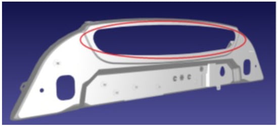
Figure 1.
Rear firewall of a sports car to which a glass panel will be bonded. Example adhesive-application trajectory (red-line) that can be traveled with speeds based on the radius of curvature.
The S-curve trajectory planning method proposed in this work is particularly well suited to applications with this type of requirement, where it is possible to identify path sections that can be followed with constant levels of different speeds.
By exploiting the knowledge of the trajectory and defining two constant velocity levels associated with low and high-curvature segments, the proposed procedure automatically generates the corresponding motion law governing the transitions between them. In this way, the dispenser can be properly adjusted to ensure uniform adhesive distribution while allowing higher velocities wherever the curvature permits. Naturally, the method can be generalized to handle multiple velocity and curvature levels.
The remainder of this section is organized as follows. The proposed trajectory planning strategy and the rationale behind the speed-based control approach are presented in Section 2.1. Section 2.2 delineates the process of parameterizing the trajectory and establishing the law of motion. The non-linear filter of the controller regulates the speed transitions necessitated by the law of motion, as illustrated in Section 2.3. Section 2.4 addresses the transitions to lower speeds, which require the anticipation of the setpoints to ensure that the speed reaches the intended value at the intended point.
2.1. The Developed Trajectory Planning Strategy
The proposed trajectory planning method relies on a path parameterization (e.g., by points) expressed in terms of the curvilinear abscissa s (see Section 2.2). In principle, a path can be traversed at a wide range of velocities, depending on the specific task requirements. However, for the sake of clarity, the motion law considered in this work is defined using only two discrete velocity levels: a higher speed , assigned to path segments with large radii of curvature, and a reduced speed , applied to segments with small radii of curvature.
In practical implementations, it is generally advisable to introduce a minimum curvature threshold , below which the velocity must not exceed a predefined safety limit (see Figure 2, left). This specific aspect will not be further analyzed here since the trajectory is assumed to be known in advance. Under this assumption, potential critical points (e.g., sharp corners or edges) can be identified a priori, and suitable connecting segments with appropriately reduced velocities can be inserted to ensure safe and reliable execution.
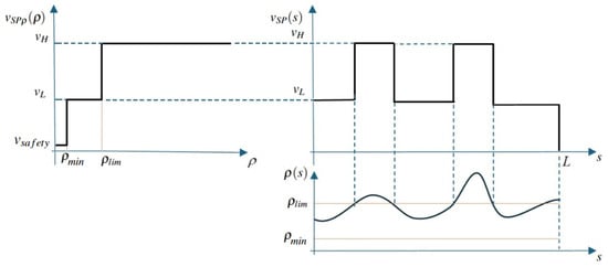
Figure 2.
Speed levels based on the radius of curvature (left) and example of a speed setpoint as a function of the curvilinear abscissa (right).
The speed setpoint is thus defined as a step function , determined with respect to a threshold value of the radius of curvature .
Since the radius of curvature is itself known as a function of the curvilinear abscissa s, the speed setpoint along the trajectory can be expressed as the composite function of and , namely, the following:
Figure 2 (right) illustrates a hypothetical profile of as a function of the curvilinear abscissa s. The profile alternates between the values and , depending on whether the radius of curvature is below or above the threshold . In this framework, denotes the desired speed setpoint along the path and must be distinguished from the actual velocity , which is obtained from through the low-pass filtering procedure described in Section 2.3. The displacement is then computed by integrating the filtered velocity .
Since assumes a nonzero value at ( or , depending on the radius of curvature at the beginning of the path), the motion is initiated even if the actual velocity is initially zero. Conversely, is set to zero at the end of the trajectory as the motion must terminate with zero velocity.
As will be discussed discussed in Section 2.4, the velocity profile must be corrected when the setpoint transitions from to . Specifically, the velocity at the entrance of a curved segment must already conform to the lower value. This adjustment is accomplished by anticipating the setpoint change over a small spatial offset , which can be determined from the filter parameters.
Section 2.4 details the proposed recursive method: the time law at a given instant t is obtained by numerically integrating the velocity , which is generated by the low-pass filter. The filter input is , evaluated at the curvilinear abscissa determined in the previous integration step, where denotes the sampling time.
2.2. Parameterization of the Path and Definition of the Speed Setpoints
The motion of a robot, or of its end-effector, is defined by a trajectory composed of a geometric path—representing a time-independent curve—and an associated law of motion that specifies how this path is traversed.
Such curves can be characterized by specific properties (e.g., continuity, differentiability, passage through prescribed points, and continuity of curvature), which in turn lead to different mathematical representations: explicit or implicit equations, parametric forms, Fourier series, discrete descriptions through sampled or control points, splines, quintics, Bézier curves, and others. Further classifications can be made according to the coordinate system adopted to represent the points of the curve (Cartesian, polar, spherical, cylindrical, etc.). Finally, a curve can also be described through differential equations together with suitable initial conditions.
In this work, the natural parametric form is employed, namely, a parametric representation where the arc length, or curvilinear abscissa, is used as the parameter, conventionally denoted by s.
Figure 3 depicts a curve , where , , and denote the Cartesian coordinates of a generic point on the curve. Provided that the curve is sufficiently smooth, the Frenet framework defines the unit vectors at each point as
with , , and denoting the tangent, normal, and binormal vectors, respectively.
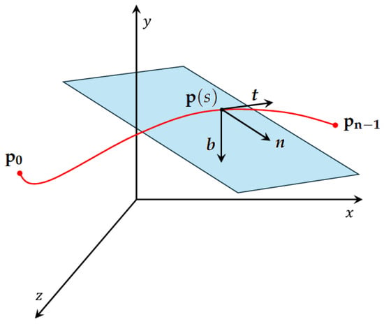
Figure 3.
Path representation of a trajectory.
The curvature of the curve is given by the norm of the vector :
or
or, in the case of a generic parameterization with a parameter u
The latter formula is introduced because, in this work, the curve is defined by transit points and computed through three independent cubic splines , , and , all parameterized by the same generic variable . The natural representation based on the curvilinear abscissa s is employed only for computations related to the time law. The function can then be expressed as a curvilinear integral as follows:
Since the splines belong to class , the first and second derivatives are continuous. Hence, the radius of curvature is expressed as
or, if parametrized in u,
The law of motion, commonly referred to as the S-curve, describes how a path is traversed over time. It characterizes the motion of a point along a curve divided into segments where the velocity increases, remains constant, decreases, or—less frequently—pauses (the latter are generally neglected). In general, the motion profile is expressed as a function , which provides the curvilinear abscissa and its derivatives at a given instant t and thus the coordinates of the point .
For the motion of the end-effector of a robot, the function must satisfy specific properties to ensure feasibility at the actuator level since the robot joint coordinates and their derivatives must be obtained at any instant t through the inverse kinematics associated with . As it is not known a priori whether the actuator limits permit the direct realization of a given time law, numerous approaches have been proposed in the literature to incorporate these constraints into motion planning (see [17,18]).
Typically, such problems are addressed offline by applying a temporal dilation of the time law—especially in simple cases where joint accelerations are excessive—until all constraints are satisfied.
In this work, such limitations are not considered, and it is assumed that the robot can execute the law of motion without constraints.
The method proposed in this paper takes as input the maximum allowable values of speed, acceleration, and jerk. If the drive constraints are not satisfied, the analysis can be repeated by adjusting these values and reapplying the method.
A wide variety of motion laws exists in the literature (polynomial, trapezoidal, modified trapezoidal, trigonometric, exponential, spline-based, etc.). Among them, seven-segment trapezoidal profiles are widely adopted since the acceleration can be explicitly shaped by prescribing the duration of each segment with constant jerk. However, despite their flexibility, trapezoidal laws do not permit direct control of the maximum velocity and acceleration as they are typically defined by specifying the displacement and total duration of the motion.
In contrast, the proposed method directly uses the maximum allowable values of velocity, acceleration, and jerk, combining them with the geometric characteristics of the path—particularly its radius of curvature—to define the resulting law of motion. As already discussed, the algorithm relies on a controller that enforces the velocity setpoint while accounting for the global constraints:
to generate the function , which tracks the reference value . The latter is linked to the radius of curvature in s, as described in Section 2.1.
The block diagram in Figure 4 illustrates the generator of the time law together with its input and output variables. In addition to , the filter also provides and , while the displacement is computed by trapezoidal integration of .
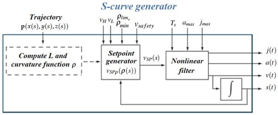
Figure 4.
S-curve generator of the law of motion.
The S-curve generator operates according to the pseudocode reported in Algorithm 1, where , , and are auxiliary local variables.
| Algorithm 1 S-curve generator |
|
At time t = 0, the system is initialized with (the beginning of the path) and (the initial velocity is always zero).
Most of the computation is performed by the non-linear filter, which will be discussed in the following section. This type of filter, or variants of it, is commonly employed for online trajectory generation; however, in such cases the filtered quantity is typically the actuator rotation, obtained through the inverse kinematics of the system, rather than the speed. If the filter setpoints can be updated online, moving targets can be tracked, provided that the curvature radius of the varying path can be computed in real time. Consequently, the method could also be applied to mobile robots that must avoid obstacles suddenly appearing along their path. In this context, additional velocity constraints (e.g., by introducing a safety limit ) may be required to prevent excessive centripetal forces in the presence of small curvature radii .
To illustrate the operation of the method, consider the time law corresponding to the simple path from point A to point D shown in Figure 5. The path consists of two circular arcs of radius r, connected by a straight segment that must be traveled at twice the velocity of the curved portions.
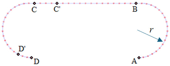
Figure 5.
Illustrative trajectory from point A to point D.
Figure 6 shows the target velocity (dashed line) during the computation of the time law. At each integration step, starting from and , the local curvature radius and the corresponding target velocity are evaluated.
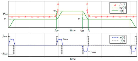
Figure 6.
Setpoint and output , , and computed by S-curve generator for the path in Figure 5.
At the beginning of the path, is equal to and remains at this value until at . At this instant, the curved section ends and the radius of curvature reaches so that the target velocity switches to . However, the transition from to must occur before (specifically at ) since the effect of the filter delay must be considered in order for the velocity to already match at the entrance of the new curved segment. The anticipation instant can be computed as the acceleration and jerk values during the transition from to are known (see Section 2.4).
A similar consideration applies to the final part of the motion, where the filter must guarantee that the total displacement corresponds exactly to the path length L. In this case, the speed setpoint is set to zero at the position , where is the distance traveled during the time required by the filter to bring the velocity to zero.
In Figure 6, the green line represents the actual velocity, which smoothly follows the setpoint while satisfying the acceleration and jerk constraints, as highlighted in the lower graph of the figure.
2.3. The Non-Linear Filter
Non-linear filters are frequently employed for online generation of robot motion laws, for instance in tasks such as tracking or picking moving objects. More generally, given a setpoint signal and constraints on its derivatives, and , the controller integrates the signal to generate a profile u that follows the setpoint while respecting the bounds on the first and second derivatives. Figure 7 illustrates the filtering scheme in its discrete form, where z denotes the state variable. Without entering into further detail (for which the reader is referred to [43]), the pseudo-code of the function implemented by the controller C to compute the control signal is reported in Algorithm 2.
| Algorithm 2 Controller |
|
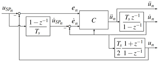
Figure 7.
Non-linear discrete filter. C is the controller.
The inputs are the sampling time , the maximum admissible values of the first and second derivatives of the signal ( and ), the error with respect to the setpoint and its derivative (e and ), and, finally, the derivative of the output (). The symbols z, m, , and are auxiliary variables introduced for the computation.
The function described above is internally invoked by the filter according to the steps reported in Algorithm 3, which implements a discrete integrator followed by a trapezoidal one in order to generate the output shown in Figure 4. Algorithm 3 also computes the derivative of the setpoint, whose error is required by the controller. This procedure, denoted as Filter.Execute, takes as inputs the constraint values and , the time variable t, the sampling step , and the setpoint value at time t. It then outputs the variables , , and , consistent with the scheme described above. In the pseudocode, the case is explicitly handled in order to initialize the variables prior to integration.
| Algorithm 3 Filter.Execute |
|
The variables , , and are simple global support fields of the Filter object. As an illustrative example, Figure 8 shows the filter output (solid red line) in response to a generic setpoint signal , represented by the brown dash-dotted line. The dashed green line and the dotted blue line instead represent the profiles of and , respectively, generated by the filter while enforcing the constraints and .
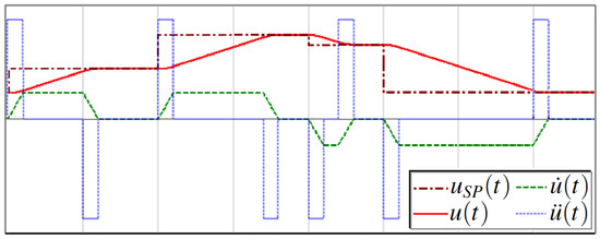
Figure 8.
, , and generated by the filter in tracking the setpoint .
It is important to emphasize that, in the S-curve generator, the filter is applied to the velocity rather than to the displacement so that the setpoint is defined as and the control variables correspond to acceleration and jerk; consequently, as illustrated in Figure 4, the displacement is obtained through an additional integration of the filter output . In this filter application, and take on the values and , respectively. In this way, the motion starts from rest and accelerates smoothly, while takes the value of the setpoint as an input parameter. Since the filter is designed to track this reference while respecting acceleration and jerk constraints, the resulting velocity corresponding to the filter output cannot exceed nor become negative given that the saturation of the jerk phases is managed by adopting a correction of the setpoint function explained in the following paragraph, which works on the basis of a local displacement large enough to guarantee the presence of both positive and negative jerk phases.
2.4. Correction of the Setpoint Function
This section addresses the problem arising in the transition from to . Consider again the example path in Figure 5, with the minimum admissible curvature in the two curved sections AB and CD during the motion from A to D. Figure 9 shows the radius of curvature, its limit value , and the speed setpoint as functions of the curvilinear abscissa s. Applying the S-curve generator to these parameters yields the corresponding time law of motion, as discussed in the previous sections. Due to the filtering effect, the actual velocity (green solid line), which follows the target (black dotted line), reaches the new values with a delay. This does not pose any issues at the beginning of the path since the velocity naturally increases from zero to the target value ( if the trajectory starts with a straight segment, otherwise ). Similarly, the transition from low to high speed at is not problematic because the higher velocity is achieved once the straight segment has already begun.

Figure 9.
Corrected speed setpoint signal for the path in Figure 5.
However, the reverse transition at is critical: the velocity decreases along the curved section, where it should already be at the lower value. For this reason, the change in the setpoint must be anticipated to the abscissa . This adjustment applies not only at but also at , i.e., in every case where the speed must be reduced, as illustrated by the green dashed line. To achieve this effect, the filter input must be replaced by the corrected function shown in the figure.
At each time step, the algorithm evaluates the curvature at the current continuous value of the curvilinear abscissa s. The speed setpoint is then determined by comparing this to the threshold . The corrected setpoint function is implemented by comparing the current s to the pre-computed, continuous anticipation points . This ensures that the setpoint switching is not tied to the discrete path points used for spline construction.
The anticipation can be computed since the filter strictly enforces the bounds on and . As shown in Figure 10, during a generic velocity reduction from to , the filter generates a trapezoidal acceleration profile.
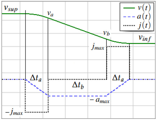
Figure 10.
Speed reduction section of the law of motion.
Consequently, the traveled distance can be determined from the transition time. If is the duration at maximum negative (and positive) jerk and the duration at maximum negative acceleration, then
The total distance traveled over the three phases is obtained as the area under the velocity curve, i.e., , where
The intermediate velocity values appearing in Equation (11) can be computed as follows:
These formulas must be revised when the constraints prevent the attainment of , causing the trapezoidal acceleration profile to degenerate into a triangular one. This occurs when . In this case, the actual maximum acceleration at the vertex, and the time to reach it, can be computed as reported in Equation (13).
The displacement can still be evaluated using the previous formulas by setting and substituting for . Returning to the calculation of in the example, it suffices to set and , while is obtained by imposing and . In a generic path, however, the final speed reduction may start either from or from , depending on the radius of curvature of the last segment. To generalize, let denote the displacement required for the reduction from to and () the one needed to stop the motion from (). Denoting by L the total path length, the corrected setpoint function can then be derived as shown in Algorithm 4. In short, the procedure uses the local variable to store the final displacement interval and returns zero if s corresponds to the end of the path. If s lies within a speed reduction segment and the current speed setpoint is not , the setpoint is set to . In all other cases, the function simply returns the original value .
| Algorithm 4 correction |
|
3. Results
This section provides representative application examples to demonstrate the efficacy of the proposed method. The goal is to provide practical examples of the trajectory planning strategy and the S-curve generator in action, emphasizing both the implementation aspects and the resulting motion profiles. The selected examples illustrate how the corrected setpoint function guarantees seamless transitions and adherence to kinematic limits based on the interaction between the geometry of the path and the constraints on velocity, acceleration, and jerk. The purpose of these case studies is to serve both as a proof of concept and as a guideline for applying the proposed method to more complex robotic trajectories.
3.1. Planar Trajectory—Fermat’s Spiral
Figure 11 illustrates a complex planar trajectory, where the dots represent the sampling points. The path is composed of two spline segments generated from a set of points () computed according to Fermat’s spiral equation.
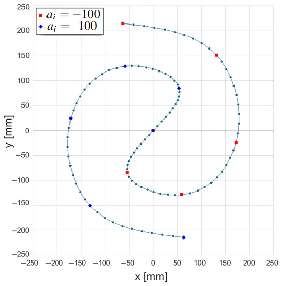
Figure 11.
Path based on Fermat’s spiral.
The Cartesian coordinates of the points are defined as follows:
where and distinguish the two branches of the curve (red vs. blue points in the figure), as reported in Table 1. The additional parameters used in this example are summarized in Table 2.

Table 1.
Transit points of the path of Figure 11 based on Fermat’s spiral.

Table 2.
Parameters and constraints of the pat based on Fermat’s spiral.
This path is characterized by a highly variable radius of curvature along the curvilinear abscissa, as shown in Figure 12, which makes it suitable for testing the behavior of the proposed procedure. The figure highlights the threshold value and reports both the theoretical speed setpoint and the corrected one .
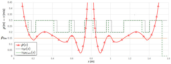
Figure 12.
Radius of curvature and theoretical and corrected setpoints.
The velocity setpoint is defined by the transitions occurring at the points where the radius of curvature crosses the critical value—either increasing above or decreasing below it—as indicated in the figure by the intersections of the curvature profile with the orange horizontal line.
However, in order to ensure a slow velocity at the beginning of the “slow” sections of the trajectory, the setpoint must be switched in advance, allowing the filter sufficient time to reduce the speed to the required value. This anticipation is represented by the horizontal displacement between the falling edges of the two reference speeds. Figure 13 shows the resulting motion law profiles generated by the proposed S-curve method. The overall movement lasts approximately 6.8 s.
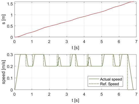
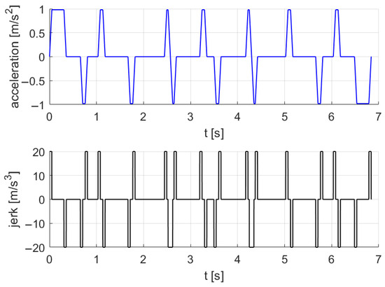
Figure 13.
Resultant law of motion calculated with the proposed procedure. Ref. speed corresponds to .
As illustrated in the velocity graph, the filter adapts the motion even when the maximum value cannot be attained. The last two graphs report the acceleration and jerk profiles, clearly showing that the imposed constraints are satisfied.
3.2. 3D Trajectories
Three 3D curves were considered as additional examples to validate the results of the proposed procedure. In all cases, a spline sampling step of and a sampling time of were adopted. The specific parameters, which vary across the different curves, are summarized in Table 3. A brief description of the shape of each curve is provided in the following sections, along with the corresponding 3D path and top-view representations.

Table 3.
Parameters for the considered 3D curves.
3.2.1. Elliptic Helix Curve
As a first example of a 3D curve, a conical helix with an elliptical winding and a linearly varying radius was considered (Figure 14). The helix spans two turns and is defined by points parameterized as with , resulting in . In the Cartesian formulation (Equation (15)), the radius varies differently along the two horizontal axes—ranging from 0 to along the major axis (x) and from 0 to along the minor axis (y)—while the vertical displacement varies linearly from to along the z-axis. This configuration enables testing of the procedure in a simple 3D spline scenario, for instance, by adopting .
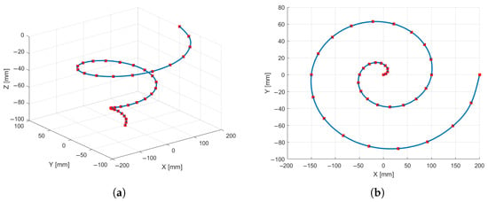
Figure 14.
Elliptic helix trajectory: (a) 3D view. (b) Top view.
3.2.2. Viviani’s Curve
As a second example, Viviani’s curve was selected—a spatial figure-eight trajectory (Figure 15) obtained from the intersection of a sphere with a cylinder tangent to the sphere and passing through two of its poles. The resulting curve is closed and exhibits a cyclically varying radius. This configuration enables the evaluation of a periodic spline case in which continuity of the derivatives between the first and last points is enforced. The curve is defined with and sampled at points, with the parameter t incremented by steps of from to , according to Equation (16).
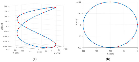
Figure 15.
Viviani’s trajectory: (a) 3D view. (b) Top view.
3.2.3. Serpentine Curve
The final curve, shown in Figure 16, was obtained by projecting a planar serpentine path onto a portion of a spherical cap. The planar curve was generated using a total of points—10 points for each straight segment of length and 20 points for each lateral semicircle of radius . This configuration produces an overall increase in the average radius of curvature while periodically maintaining local minima at very low values.
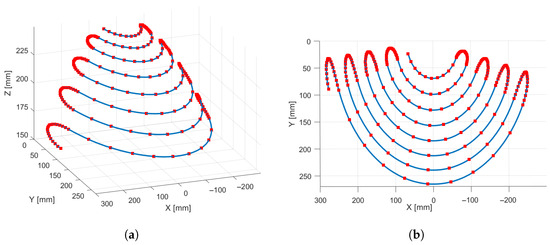
Figure 16.
Serpentine trajectory: (a) 3D view. (b) Top view.
3.3. Normal Acceleration and Execution Time Data
For each considered case, the maximum centripetal acceleration and the motion execution time were analyzed. As benchmark references, two limiting scenarios were examined: one with a low constant velocity and another with a high constant velocity along the entire path, with acceleration and deceleration phases only at the beginning and end of the motion. The low-velocity case represents the motion law that would be required in the absence of the proposed procedure, whereas the high-velocity case was evaluated solely to provide reference values for an ideal high-performance condition. Subsequently, the proposed procedure was assessed both with and without the anticipated velocity reduction and in combination with the activation or deactivation of the safety velocity control. For each tested trajectory, Figure 17, Figure 18, Figure 19, Figure 20 and Figure 21 illustrate the normal acceleration as a function of the curvilinear abscissa, while Table 4 summarizes the corresponding maximum normal acceleration and motion duration for all analyzed cases. The application of the safety velocity was considered only in cases where it was deemed meaningful. The column reduction reports the percentage decrease in centripetal acceleration with respect to the high constant velocity case, while the column reduction indicates the reduction in motion time relative to the same reference case.
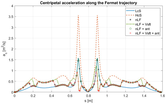
Figure 17.
Centripetal acceleration as a function for the Fermat trajectory. LcS = Low constant Speed, HcS = High constant Speed, nLF = non-Linear Filter, nLF + Vsft = non-Linear Filter with safety velocity, nLF + ant = non-Linear Filter with anticipation, and nLF + Vsft + ant = non-Linear Filter with safety velocity and anticipation.
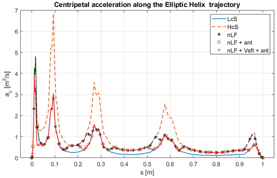
Figure 18.
Centripetal acceleration as a function for the Elliptic helix trajectory. LcS = Low constant Speed, HcS = High constant Speed, nLF = non-Linear Filter, nLF + ant = non-Linear Filter with anticipation, and nLF + Vsft + ant = non-Linear Filter with safety velocity and anticipation.
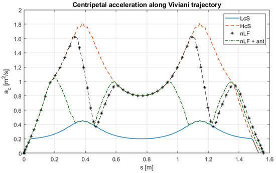
Figure 19.
Centripetal acceleration as a function for Viviani’s trajectory. LcS = Low constant Speed, HcS = High constant Speed, nLF = non-Linear Filter, and nLF + ant = non-Linear Filter with anticipation.
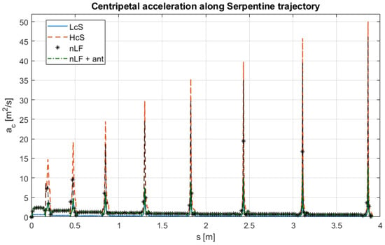
Figure 20.
Centripetal acceleration as a function for Serpentine trajectory. LcS = Low constant Speed, HcS = High constant Speed, nLF = non-Linear Filter, and nLF + ant = non-Linear Filter with anticipation.
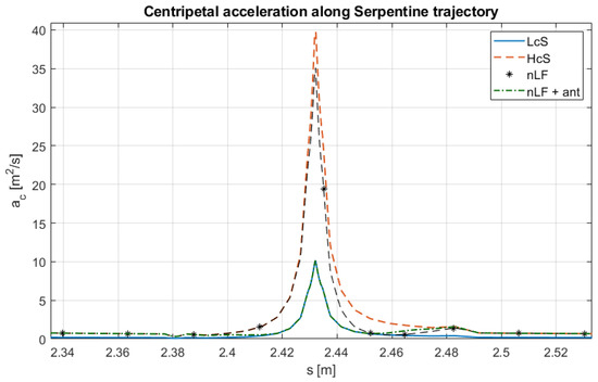
Figure 21.
Zoom of centripetal acceleration as a function for Serpentine trajectory. LcS = Low constant Speed, HcS = High constant Speed, nLF = non-Linear Filter, and nLF + ant = non-Linear Filter with anticipation.

Table 4.
Centripetal acceleration () and execution time () for the 3D trajectories for different motion planning strategies. LcS = Low constant Speed; HcS = High constant Speed; nLF = non-Linear Filter; ant = anticipation; Vsft = safety velocity.
4. Discussion
The developed procedure aims to generate a motion law for a robot end-effector by connecting a sequence of trajectory segments at different constant velocity levels under controlled dynamic constraints.
The current implementation is a stand-alone Delphi application that off-line computes time-sampled motion profiles from geometric input and kinematic limits. The algorithm runs in real time on a standard PC, confirming its low computational load and indicating feasibility for future on-line deployment within typical industrial robot control cycles (1–4 ms).
The velocity setpoint is reduced when the radius of curvature decreases, thereby limiting the resulting centripetal accelerations. The procedure has been made more robust by introducing a minimum threshold for , below which a very low safety velocity is enforced. Furthermore, during deceleration phases, the velocity reduction is anticipated so that regions of high curvature are approached with already limited velocity values. To evaluate these three aspects, several trajectories were analyzed under different conditions.
In the first case (Fermat’s spiral), applying the proposed procedure without the safety speed control, compared to the constant low-speed case, results in a reduction in the execution time from to () while maintaining the same maximum centripetal acceleration as in the low-speed case. Conversely, the early speed reduction provides no significant advantage and slightly increases the execution time. When the safety speed control is enabled, the maximum centripetal acceleration decreases substantially ( compared to the HcS and compared to the LcS), while the execution time is further reduced by approximately . These results are also illustrated in Figure 17, where the acceleration corresponding to the nLF + ant configuration increases during high-speed phases yet remains below the maximum value observed in the LcS case.
For the elliptic helix trajectory, similar improvements are observed in the execution time, which decreases from at low speed to slightly above (−20.3% of reduction) when the proposed procedure is applied. In this case as well, the anticipation of the velocity reduction does not yield any tangible benefit as it slightly increases the execution time without improving the maximum acceleration. Conversely, activating the safety speed control proves advantageous, reducing the centripetal acceleration (−42.6% vs. HcS and −18.5% vs. LcS) at the beginning of the motion—where assumes very low values—while still maintaining the execution time at (a −15.8% of reduction), as shown in Figure 18. For the last two curves analyzed, the results of the safety speed activation are not reported because it does not intervene. For the Viviani’s curve, the advantage of introducing the speed reduction anticipation is observed as the acceleration decreases from 1.62 m/s2 to 1.04 m/s2 while only slightly lengthening the execution time, which increases from 5.31 s to 5.89 s. Figure 19 shows that the nLF+ant case exhibits a trend of centripetal acceleration with values approximately halved compared to the HcS case. However, for this type of curve, the method offers no advantages because the radius of curvature does not vary much, remaining in a range between approximately 0.08 m and 0.2 m; therefore, the maximum value of centripetal acceleration is greatly affected by the speed increase from to .
This behavior is not observed in the last case, corresponding to the Serpentine trajectory, where the maximum centripetal acceleration increases from to when anticipation is not adopted. Conversely, with anticipation enabled, it remains at —thus comparable to the low-speed motion—while simultaneously halving the execution time. The influence of anticipation is illustrated in Figure 20 and Figure 21, where it can be observed that the NLF + ant curve closely follows the LcS profile in the peak regions.
The algorithm was tested with a sampling time of , typical of high-performance robotic controllers. Although larger sampling times may affect tracking accuracy and smoothness, the filter guarantees compliance with dynamic constraints. A quantitative sensitivity analysis to will be addressed in future work.
The proposed method is inherently three-dimensional and has been validated on both planar and spatial trajectories. The study focuses on end-effector position planning, which constitutes the core of most industrial applications. Extension to full-pose and joint-space planning is conceptually straightforward and will be addressed in future work.
Beyond these comparative aspects, several broader considerations can be drawn. The proposed method is conceived as a planning phase in the operational (task) space, where smoothness and dynamic feasibility are primarily evaluated with respect to the end-effector motion. It should be noted, however, that implementation on a real industrial robot would require an additional inverse kinematics step and that joint-space feasibility (e.g., actuator limits and torque capabilities) remains a distinct issue. Nevertheless, the proposed framework helps create smoother movements, providing a dynamically consistent velocity profile that can enhance the overall trajectory quality once mapped into joint space.
It is also important to remark that kinematic derivatives in the operational space do not translate linearly into those in the joint space, especially in the vicinity of singular configurations. Therefore, the proposed approach should be regarded as a generator of an ideal reference profile for the end-effector, which could subsequently be refined through an additional adaptive time-scaling stage. The present contribution focuses on the off-line planning phase, which could naturally be integrated into a broader motion design workflow. For instance, once the law of motion has been generated, it can be provided to a robot-specific simulator. If this simulation reveals violations of joint-level constraints—such as velocity, acceleration, or torque limits—the designer can iteratively adjust the bound values of v, a, and j and regenerate accordingly. This iterative process would allow maintaining the dynamic smoothness guaranteed by the proposed method while ensuring feasibility with respect to the physical limitations of the specific manipulator.
5. Conclusions
Curvature-based feedrate scheduling and jerk-limited rate limiting are well-established research areas. The proposed contribution lies in the systematic integration of these techniques within a unified framework that addresses some limitations of conventional trajectory planning pipelines. The distinctive elements of the proposed approach are as follows:
- Velocity-space filtering with a dynamic setpoint. Many trajectory generators apply non-linear filters to displacement (or joint position) commands. In contrast, the proposed approach applies the non-linear filter directly to the reference velocity signal . Combined with the fact that the setpoint is a function of the robot’s current state along the path, this creates a closed-loop behavior within the trajectory generator itself. This structure enables dynamic adaptation of the velocity profile during execution if the path changes (for instance, in mobile robots performing obstacle avoidance)—a flexibility not typically achievable with purely offline methods. Although this extension involves challenges to be addressed, it could open the way to an online implementation of the procedure.
- Anticipation of velocity transitions in the curvilinear abscissa domain. Many standard feedrate scheduling methods compute a velocity profile that satisfies curvature constraints and then filter it in the time domain to limit jerk and acceleration. This filtering introduces a delay that can cause the robot to enter a high-curvature segment while still moving at excessive speed. The proposed method introduces an explicit, precomputed geometric correction in the curvilinear abscissa domain s. The anticipation distance required to decelerate from to under the limits and is computed analytically, and the setpoint function is modified a priori into . This ensures that the target velocity equals exactly at the curve entry—a guarantee that purely temporal filters cannot provide without such geometric pre-processing. The introduction of the correction on the speed setpoint also allows the S-curve generator to work without generating overshoots on the speed trend.
- Provided guarantees. The method ensures the following:
- The kinematic constraints and are satisfied at every point along the trajectory.
- The velocity at the entrance of a high-curvature segment is exactly due to the anticipation law.
- Transitions between different velocity levels occur with trapezoidal or triangular acceleration profiles (S-curves), maximizing smoothness.
- The velocity remains stably constant at the prescribed level once a transition is completed.
In summary, the novelty does not lie in a single algorithmic block but in the hybrid architecture that combines intelligent geometric pre-processing with a dynamic filter operating in the velocity domain, providing both geometric (curvature–speed compliance) and dynamic (jerk and acceleration limitation) performance guarantees.
The proposed approach was developed and validated in an ideal, deterministic setting, assuming exact and noise-free knowledge of the path geometry (e.g., CAD paths or dense splines). Under these conditions, is well defined, and transitions around are sharp and deterministic. The current switching logic for does not integrate a hysteresis mechanism () and does not apply a low-pass filter to , features that would increase robustness without altering the algorithmic structure. This limitation will be addressed in future extensions to improve performance in noisy or uncertain contexts.
The method applies to smooth parametric trajectories and is not intended for paths with tangent discontinuities. The simulation results confirm strict compliance with the imposed acceleration and jerk limits. Nevertheless, future work will include experimental validation on realistic process trajectories and quantitative performance assessment.
Future developments will also consider speed-dependent acceleration limits derived from actuator torque–speed characteristics. Integrating this function into the non-linear filter and setpoint correction would extend the method to actuators with non-constant torque capabilities while preserving the core principles of curvature-based S-curve planning.
Furthermore, a systematic sensitivity and ablation analysis would be valuable to quantify the effect of each component and parameter. Qualitative observations indicate that setpoint anticipation significantly reduces contour errors, while stricter acceleration and jerk limits improve smoothness at the expense of execution time. The method remains stable across practical sampling times, and the curvature threshold governs the trade-off between safety and cycle time. A comprehensive quantitative evaluation will be included in future work.
Author Contributions
Conceptualization, R.B., G.I., C.R. and M.T.; methodology, R.B., G.I., C.R. and M.T.; formal analysis, R.B. and M.T.; data curation, R.B.; writing—original draft preparation, R.B., G.I., C.R. and M.T.; writing—review and editing, R.B., G.I., C.R. and M.T. All authors have read and agreed to the published version of the manuscript.
Funding
This research received no external funding.
Data Availability Statement
The original contributions presented in this study are included in the article. Further inquiries can be directed to the corresponding author(s).
Conflicts of Interest
The authors declare no conflicts of interest.
Nomenclature
| Linear acceleration [m/s2] | |
| Centripetal acceleration [m/s2] | |
| Maximum linear acceleration [m/s2] | |
| Actual maximum acceleration (triangular profile) [m/s2] | |
| Binormal vector (Frenet frame) | |
| Error and error derivative in the non-linear controller | |
| Jerk [m/s3] | |
| Maximum jerk [m/s3] | |
| Curvature [1/m] | |
| L | Total path length [m] |
| Normal vector (Frenet frame) | |
| Position vector of a point on the trajectory | |
| s | Curvilinear abscissa [m] |
| Motion law (position along the path) [m] | |
| Tangent vector (Frenet frame) | |
| t | Time [s] |
| Execution time [s] | |
| Sampling time [s] | |
| u | Generic curve parameter |
| Linear velocity [m/s] | |
| High speed (for low-curvature segments) [m/s] | |
| Low speed (for high-curvature segments) [m/s] | |
| Safety velocity [m/s] | |
| Velocity setpoint as a function of s [m/s] | |
| Velocity setpoint as a function of [m/s] | |
| Corrected (anticipated) velocity setpoint [m/s] | |
| Transition distance (e.g., and ) [m] | |
| Duration of constant jerk and constant acceleration transition phases [s] | |
| Curvature radius [m] | |
| Curvature radius threshold for velocity switching [m] | |
| Minimum curvature radius of the path [m] |
References
- Bobrow, J.E.; Dubowsky, S.; Gibson, J.S. Time-optimal control of robotic manipulators along specified paths. Int. J. Robot. Res. 1985, 4, 3–17. [Google Scholar] [CrossRef]
- Shin, K.; McKay, N. Minimum-time trajectory planning for industrial robots with general torque constraints. IEEE Trans. Autom. Control 1986, 31, 491–500. [Google Scholar] [CrossRef]
- Pardo-Castellote, G.; Cannon, R.H. Proximate time-optimal algorithm for on-line path parameterization and modification. In Proceedings of the IEEE International Conference on Robotics and Automation, Minneapolis, MN, USA, 22–28 April 1996; Volume 2, pp. 1539–1546. [Google Scholar] [CrossRef]
- Biagiotti, L.; Melchiorri, C. Trajectory Planning for Automatic Machines and Robots; Springer: Berlin/Heidelberg, Germany, 2008. [Google Scholar] [CrossRef]
- Siciliano, B.; Sciavicco, L.; Villani, L.; Oriolo, G. Robotics: Modelling, Planning and Control; Springer: London, UK, 2009. [Google Scholar] [CrossRef]
- LaValle, S.M. Planning Algorithms; Cambridge University Press: Cambridge, UK, 2006. [Google Scholar] [CrossRef]
- Craig, J.J. Introduction to Robotics: Mechanics and Control, 3rd ed.; Pearson Prentice Hall: Upper Saddle River, NJ, USA, 2005; p. 832. [Google Scholar]
- Khatib, O. A Unified Approach for Motion and Force Control of Robot Manipulators: The Operational Space Formulation. IEEE J. Robot. Autom. 1987, 3, 43–53. [Google Scholar] [CrossRef]
- Hollerbach, J.M. Dynamic Scaling of Manipulator Trajectories. J. Dyn. Syst. Meas. Control 1982, 104, 239–245. [Google Scholar] [CrossRef]
- Shiller, Z.; Dubowsky, S. On Computing the Global Time-Optimal Motions of Robotic Manipulators in the Presence of Obstacles. IEEE Trans. Robot. Autom. 1991, 7, 785–797. [Google Scholar] [CrossRef]
- Elbanhawi, M.; Simic, M. Sampling-Based Robot Motion Planning: A Review. IEEE Access 2014, 2, 56–77. [Google Scholar] [CrossRef]
- Fang, Y.; Hu, J.; Liu, W.; Shao, Q.; Qi, J.; Peng, Y. Smooth and time-optimal S-curve trajectory planning for automated robots and machines. Mech. Mach. Theory 2019, 137, 127–153. [Google Scholar] [CrossRef]
- Wu, G.; Zhang, N. Kinematically constrained jerk–continuous S-curve trajectory planning. Electronics 2023, 12, 1135. [Google Scholar] [CrossRef]
- Liu, T.; Cui, J.; Li, Y.; Gao, S.; Zhu, M.; Chen, L. Time-optimal asymmetric S-curve trajectory planning of redundant manipulators. Sensors 2023, 23, 3074. [Google Scholar] [CrossRef]
- Macfarlane, S.; Croft, E.A. Jerk-bounded manipulator trajectory planning: Design for real-time applications. IEEE Trans. Robot. Autom. 2003, 19, 42–52. [Google Scholar] [CrossRef]
- Tagliavini, A.; Guarino Lo Bianco, C. η3D-splines for the generation of 3D Cartesian paths with third order geometric continuity. Robot. Comput. Integr. Manuf. 2021, 72, 102203. [Google Scholar] [CrossRef]
- Mercy, T.; Van Parys, R.; Pipeleers, G. Spline-Based Motion Planning for Autonomous Guided Vehicles in a Dynamic Environment. IEEE Trans. Control Syst. Technol. 2017, 26, 2182–2189. [Google Scholar] [CrossRef]
- Kwangjin, Y. An Efficient Spline-Based RRT Path Planner for Nonholonomic Robots in Cluttered Environments. In Proceedings of the International Conference on Unmanned Aircraft Systems (ICUAS), Atlanta, GA, USA, 28–31 May 2013; pp. 288–297. [Google Scholar] [CrossRef]
- Lee, A.C.; Lin, M.T.; Pan, Y.R.; Lin, W.Y. The feedrate scheduling of NURBS interpolator for CNC machine tools. Comput. Aided Des. 2011, 43, 612–628. [Google Scholar] [CrossRef]
- Liu, M.; Huang, Y.; Yin, L.; Guo, J.; Shao, X.; Zhang, G. Development and implementation of a NURBS interpolator with smooth feedrate scheduling for CNC machine tools. Int. J. Mach. Tools Manuf. 2014, 87, 1–15. [Google Scholar] [CrossRef]
- Du, X.; Huang, J.; Zhu, L.M. A Complete S-Shape Feed Rate Scheduling Approach for NURBS Interpolator. J. Comput. Des. Eng. 2015, 2, 206–216. [Google Scholar] [CrossRef]
- Nie, M.; Zhu, T.; Li, Y. NURBS Interpolator with Minimum Feedrate Fluctuation Based on Two-Level Parameter Compensation. Sensors 2023, 23, 3789. [Google Scholar] [CrossRef]
- Zhao, H.; Zhu, L.M.; Ding, H. A real-time look-ahead interpolation methodology with curvature-continuous B-spline transition scheme for CNC machining of short line segments. Int. J. Mach. Tools Manuf. 2013, 65, 88–98. [Google Scholar] [CrossRef]
- Hu, Y.; Jiang, X.; Huo, G.; Su, C.; Wang, B.; Li, H.; Zheng, Z. A novel feed rate scheduling method with acc-jerk-continuity and round-off error elimination for non-uniform rational B-spline interpolation. J. Comput. Des. Eng. 2023, 10, 294–317. [Google Scholar] [CrossRef]
- Guo, P.; Wu, Y.; Yang, G.; Shen, Z.; Zhang, H.; Zhang, P.; Lou, F.; Li, H. A Feedrate Planning Method for the NURBS Curve in CNC Machining Based on the Critical Constraint Curve. Appl. Sci. 2021, 11, 4959. [Google Scholar] [CrossRef]
- Nie, M.; Wan, Y.; Zhou, A. Real-Time NURBS Interpolation under Multiple Constraints. Comput. Intell. Neurosci. 2022, 1, 7492762. [Google Scholar] [CrossRef]
- Chen, Y.; Li, L. Predictable Trajectory Planning of Industrial Robots with Constraints. Appl. Sci. 2018, 8, 2648. [Google Scholar] [CrossRef]
- Lin, M.T.; Tsai, M.S.; Yau, H.T. Development of a dynamics-based NURBS interpolator with real-time look-ahead algorithm. Int. J. Mach. Tools Manuf. 2007, 47, 2246–2262. [Google Scholar] [CrossRef]
- Fang, Y.; Gu, C.; Zhao, Y.; Wang, W.; Guan, X. Smooth trajectory generation for industrial machines and robots based on high-order S-curve profiles. Mech. Mach. Theory 2024, 201, 105747. [Google Scholar] [CrossRef]
- Wang, L.; Liu, Q.; Sun, P.; Lv, S.; Yang, R.; Yang, Z. Dynamic look-ahead feedrate scheduling method based on sliding mode velocity control. Sci. Rep. 2024, 14, 15424. [Google Scholar] [CrossRef]
- Lozer, F.; Scalera, L.; Boscariol, P.; Gasparetto, A. Planning optimal minimum-jerk trajectories for redundant manipulators. Robot. Auton. Syst. 2025, 192, 105049. [Google Scholar] [CrossRef]
- Dai, G.; Zhang, Q.; Xu, B. A novel framework for trajectory planning in robotic arm developed by integrating dynamical movement primitives with particle swarm optimization. Sci. Rep. 2025, 15, 29656. [Google Scholar] [CrossRef] [PubMed]
- Qiao, Y.; He, X.; Li, Z. Motion Planning of 3D Nonholonomic Robots via Curvature-Constrained Vector Fields. In Proceedings of the 2024 IEEE 63rd Conference on Decision and Control (CDC), Milan, Italy, 16–19 December 2024; pp. 5807–5812. [Google Scholar] [CrossRef]
- Camacho, E.F.; Bordons, C. Model Predictive Control, 2nd ed.; Springer: London, UK, 2007. [Google Scholar] [CrossRef]
- Passenberg, C.; Peer, A.; Buss, M. A survey of environment-, operator-, and task-adapted controllers for teleoperation systems. Mechatronics 2010, 20, 787–801. [Google Scholar] [CrossRef]
- Shkolnik, A.; Tedrake, R. Path planning in 1000+ dimensions using a task-space Voronoi bias. In Proceedings of the 2009 IEEE International Conference on Robotics and Automation, Kobe, Japan, 12–17 May 2009. [Google Scholar] [CrossRef]
- Spong, M.W.; Hutchinson, S.; Vidyasagar, M. Robot Modeling and Control; John Wiley & Sons: Hoboken, NJ, USA, 2005. [Google Scholar]
- Legnani, G.; Fassi, I. Robotica Industriale; Città Studi Edizioni: Torino, Italy, 2019. [Google Scholar]
- Pham, H.; Pham, Q.C. A New Approach to Time-Optimal Path Parameterization Based on Reachability Analysis. IEEE Trans. Robot. 2018, 34, 645–659. [Google Scholar] [CrossRef]
- Kröger, T.; Wahl, F.M. On-Line Trajectory Generation: Basic Concepts for Instantaneous Reactions to Unforeseen Events. IEEE Trans. Robot. 2010, 26, 94–111. [Google Scholar] [CrossRef]
- Kröger, T. Opening the Door to New Sensor-Based Robot Applications—The Reflexxes Motion Libraries. In Proceedings of the IEEE International Conference on Robotics and Automation (ICRA), Shanghai, China, 9–13 May 2011; pp. 1–4. [Google Scholar] [CrossRef]
- Berscheid, L.; Kröger, T. Jerk-Limited Real-Time Trajectory Generation with Arbitrary Target States. In Proceedings of the Robotics: Science and Systems (RSS), Virtual Conference, 12–16 July 2021. [Google Scholar] [CrossRef]
- Zanasi, R.; Guarino Lo Bianco, C.; Tonielli, A. Nonlinear Filters for the Generation of Smooth Trajectories. Automatica 2000, 36, 439–448. [Google Scholar] [CrossRef]
Disclaimer/Publisher’s Note: The statements, opinions and data contained in all publications are solely those of the individual author(s) and contributor(s) and not of MDPI and/or the editor(s). MDPI and/or the editor(s) disclaim responsibility for any injury to people or property resulting from any ideas, methods, instructions or products referred to in the content. |
© 2025 by the authors. Licensee MDPI, Basel, Switzerland. This article is an open access article distributed under the terms and conditions of the Creative Commons Attribution (CC BY) license (https://creativecommons.org/licenses/by/4.0/).