Abstract
An incision point acts as the pivot point when a minimally invasive surgery procedure is applied. The assistive robot arms employed for such operation must have the capability to perform a remote center of motion (RCM) at this pivot point. Other than designing RCM mechanisms, a common practice is to use a readily available spatial serial robot arm and control it to impose this RCM constraint. When this assistive robot is required to be backdriven by the surgeon, the relation between the interaction forces/moments and the motion with RCM constraint becomes challenging. This paper carefully formulates a hybrid position/force control scheme for this relationship when any readily available robot arm that is coupled with a force/torque sensor is used for an RCM task. The verification of the formulation is carried out on a readily available robot arm by implementing the additional constraints that are derived from a surgical robot application.
1. Introduction
Minimally invasive surgery (MIS) procedures involve the insertion of surgical tools and a camera system called the endoscope through incision port/s. The surgical tools are moved about using this incision port as the pivot point. The typical motion characteristics are three degrees-of-freedom (DoF) rotation about this pivot point and the translational motion of the surgical tool along the pivot point.
Surgical robots taking part in MIS procedures must have the capability of RCM at the pivot point. This capability is either acquired by the mechanism design by mechanically guaranteeing the RCM constraints [1] or by controlling the motions of a readily available robot arm to impose the virtual RCM constraint [2].
The surgical robot–surgeon interaction takes place in various forms depending on the nature of the surgical system. Master consoles are used for a telesurgery application [3], and the surgeon interacts with the surgical robot through these master consoles [4,5], which are placed away from the patient. In an assistive robot setting, the surgeon and the surgical robot are operating on the patient at the same time and location. The robot–surgeon interaction takes place through some interfaces that capture or estimate the surgeon’s needs, and the robot is controlled via these inputs, such as voice [6,7] and motion capture [8]. Another medium of surgeon–robot interaction is a purely physical one where the surgeon backdrives the surgical robot, which is holding a surgical tool [9,10].
Some robot systems are developed to be passively backdrivable (i.e., without active control). These robots are usually small in size. When the workspace of such robots is larger, because of transparency requirements in backdriving the robots, passively backdriven robots become infeasible. The common method for backdriving a robot by active control is admittance control. For instance, in [11], a model predictive admittance controller is developed to perform knee arthroplasty surgeries. The high-level controller consists of an admittance controller to map the human hand force to the robot end-effector velocities. Then, a model predictive controller (MPC) is utilized to track the joint trajectories. However, the input of MPC is the dynamic model of the robot, which calls for the precise knowledge of the robot parameters (e.g., inertia).
Although admittance control enables backdriving, additional considerations must be made when controlling a readily available robot that is required to perform RCM. One approach is to measure the interaction forces at the incision point between the surgical tool and the patient. A force-based control method is proposed for this purpose in [12]. In this work, an admittance controller is implemented in a laparoscopic surgery scenario to pivot the camera as a consequence of sensed forces at the incision point (trocar), and the angular velocity of the tool is controlled in velocity control mode. The idea is to move the robot such that trocar forces between the robot and tissue are minimized while performing RCM. Also, the future velocity of the RCM is estimated through geometrical relations and fed to the system with the help of a feedforward velocity controller, preventing the sudden change of the velocities while performing RCM. However, the determination of admittance gain requires a long calibrations season, and human force input is overseen in this scenario.
Another popular method is controlling the readily available robot arm in torque control mode (i.e., bypassing the motion controller) and imposing the RCM constraint in terms of forces calculated using the discrepancy between the RCM point and the tool axis [13]. However, such a strategy depends on the availability of the torque-mode control of the readily available robot arm and requires a good knowledge of the physical properties (e.g., mass center and inertia) of the robot arm. Furthermore, in [14], a hybrid admittance controller is developed by keeping the robot at the RCM point through position control while providing compliance at the tool (i.e., the tip point of the endoscope). However, similar to the previous study, also in this study, the mass and inertia properties of the robot have to be precisely known due to the torque-control strategy.
In addition, a target admittance model is designed to carry out RCM in an MIS scenario under the joint position control mode of a collaborative robot (cobot). An artificial potential field is formed mimicking the surgery area, and repulsive forces are generated at the end-effector when the user crosses the forbidden region (i.e., outside of the surgery area). Yet, the stability of the controller is not proved [15]. In the following years, this limitation is solved, and a variable damping gain is integrated to achieve smooth force feedback in the potential fields [2]. However, the admittance model is complex, and the RCM position error is reported up to 1.2 mm, which is non-negligible. Such an error emerges mainly due to the assigned damping gain used to generate repulsive force feedback.
Although numerous solutions are proposed in the literature to perform RCM in MIS via a readily available robot arm, to our knowledge, none of them use robot kinematics and its joint position controllers to achieve admittance control about a pivot point under the user force. The detected limitations in the current state-of-the-art are (i) large RCM point deviations, (ii) long calibration seasons, (iii) the need for modeling the robot parameters, and (iv) complex admittance control algorithms. For instance, achieving the RCM through torque control calls for the estimation of the robot parameters (i.e., mass and inertia). Velocity-control-based studies can be a promising solution to neglect those parameters, yet in this case, the trocar force is considered in admittance control instead of human force while moving the RCM to nullify this force, which requires the precise determination of admittance gain. Furthermore, hybrid admittance controllers merge the position and admittance control-based solutions; however, physical parameters of the robot (e.g., inertia) are necessary. Finally, a complex admittance model is developed to constrain the movement of the user about RCM axes with the help of repulsive forces generated via the position deviation and the damping gain. Nevertheless, large errors in maintaining the RCM position are detected because of the controller gain determination challenge. To overcome the mentioned challenges, this article proposes a hybrid control framework for backdriving the end-effector of a surgical robot about a pivot point. This hybrid controller incorporates a position-controlled subspace for maintaining the RCM constraint and an admittance-controlled subspace so that the human operator can backdrive the end-effector about the RCM by applying forces on the end-effector. The formulation of this hybrid controller is designed so that this controller can be implemented on any robot architecture that already has its own position control algorithm. It should be noted that a well-tuned position controller is already available in commercially available robot arms, which cancels the need for controller gain tuning. Regarding the hybrid controller, it is defined at the pivot point, which is the fundamental novelty of this study compared to other studies. To clarify, user forcings (i.e., forces and moments) are received from the end-effector of the robot and transferred to the pivot point since it is not possible to attach a force sensor at this point. Subsequently, a diagonal compliance matrix is defined to map those resolved forces (RCM forcings) to the RCM velocities. Depending on the task, non-zero values are identified in this matrix along the RCM axes (i.e., roll, pitch, yaw, and translation along the pivot point) to generate motion under admittance control. For the rest of the directions, a zero value is set, and robot movements due to the forcing applied by the human are constrained. A selection matrix is introduced to choose along which directions the robot can be backdriven or constrained through the robot position controller. After generating velocities along certain directions and constraining the rest of them at the pivot point, they are mapped to the joint motion demands through inverse kinematics to be tracked by the robot joint position controller or transformed into the robot’s last frame velocities so that the task-space controller of the robot can be used. The preliminary results of this work were presented in [16]. In this article, we generalized the hybrid controller formulation and conducted several experiments to demonstrate the performance of the proposed technique. The original contributions of this work are summarized as follows:
- Formulation of a new hybrid controller defined at the pivot point to carry out RCM in MIS;
- Verification of the designed control framework through a robot arm driven by a user under different admittance terms assigned for different RCM axes to perform combined (e.g., yaw and translation) and separate movements (e.g., only translation).
The rest of the paper is organized as follows: in Section 2, the generalized formulation of the hybrid controller is described; in Section 3, a case study is defined through the definition of the task and the presentation of selected robot’s kinematics; in Section 4, the experimental procedure and the results are reported; in Section 5, discussions are presented; and finally, in Section 6, conclusions and future studies are highlighted.
2. Admittance Control Formulation Around the RCM Point
General-purpose industrial or collaborative robot manipulators cannot be passively backdriven due to their high resistance to forces that are externally applied. This resistance to motion is due to using high gear-ratio speed reducers in their actuation system. The common method for backdriving such robots is (1) measuring the interaction forcing (i.e., forces and moments) between the human operator and the robot, (2) defining the dynamics between the interaction forces and motion of the robot, and (3) driving the robot using the calculated motion demand through the measured forcing and defined dynamics. This strategy is commonly termed as admittance control. The dynamics set between the interaction forcing between the human and the robot, and the robot’s motion is generally named the admittance term Y.
The admittance control of robots has been studied extensively [17,18,19]. The formulation provided in this paper differs from the previous admittance control studies since the calculations are carried out at the RCM. It is not possible to place a force/torque sensor at the RCM. Therefore, the interaction forcing measured at another location on the manipulator through a force/torque sensor is used for calculating the interaction forcing imposed at the RCM. Here, the subscripts S and R indicate the sensor’s center point and the RCM point, respectively. Superscripts s and e indicate the sensor measurement frame and the end-effector frame, respectively. The distance vector between the center of the sensor frame and the RCM point is defined by the vector . Figure 1 depicts these vectors and frames, and the dashed lines indicate a rigid connection between the force/torque sensor and the end-effector.
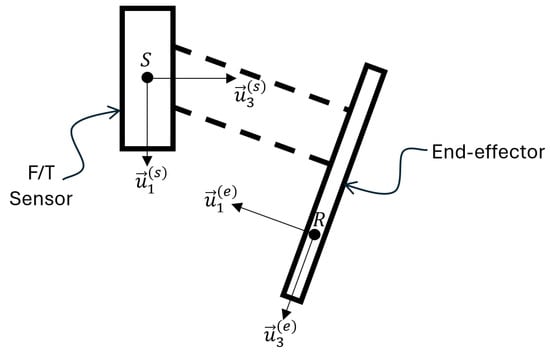
Figure 1.
Force/torque sensor’s center and frame, and RCM point and end-effector frame.
It should be noted that, in general, the imaginary RCM point’s location R is selected as a fixed location with respect to the base. However, its location changes relative to the end-effector and the force/torque sensor’s center point S throughout the manipulation. Therefore, is a function of the joint variables of the robot and the selected R location. It is also possible to design the R location as a time variable if it is required for a specific task. The ith frame resolutions of forcing vectors have the general form presented in (1).
where for , defines the force along the direction measured/calculated at point K, defines the moment along the direction measured/calculated about point K, and indicates the jth unit vector of the ith frame. Using these definitions, the ith frame resolution force vector acting at the point K can be defined as , and the ith frame resolution moment vector acting about the point K can be defined as .
Since the main objective is finding the forcings acting at the RCM point, the exact location where the human operator applies forcing is not important by using the rigid body assumption. Accordingly, the measured forcings at the force/torque sensor are moved to the RCM point using (2).
where defines the transformation matrix between the and frames, and is the cross-product matrix derived by using the skew-symmetric form of as resolved in frame . The tilde sign from this point on defines a skew-symmetric matrix representation of a vector.
When the RCM constraint is applied, the motion of the end-effector is constrained to take place along and about the RCM point (i.e., three degrees-of-freedom (DoF)) rotational motion and single-DoF translation along . Therefore, not all components of the forcings are expected to result in the motion of the end-effector. This can be achieved by designing a diagonal admittance matrix in the end-effector frame as shown in (3).
The most general form of this matrix can be modified depending on the needs of the specific application. If it is desired for the human operator not to control the rotation about or the translation along , then or components of the matrix can be selected to be zero, respectively.
The composition of the admittance terms (e.g., ) in the matrix can be selected depending on the needs of the specific application. The main aim of this paper is not to propose an admittance term formulation. Usually, a mass–damper analogy is chosen for the admittance term, which in fact results in a low-pass filter. The reader can find many works in the literature on setting the admittance term parameters [20,21]. If a mass–damper model is used for each term, then the admittance terms in the matrix can be defined as follows:
where , and are the mass and inertia parameters, and and are the linear and torsional damper parameters.
After that, the matrix is used in (5) to calculate the consequent motion in terms of task-space velocities defined in the end-effector frame .
where .
The block diagram representation of this algorithm can be developed based on a hybrid position/force control scheme [22] using a diagonal selection matrix . This selection matrix enables defining the constrained motion directions and those in which the human operator’s forcings can dictate the motion. Figure 2 shows the block diagram of the hybrid position/force control scheme for implementing admittance control about the RCM.
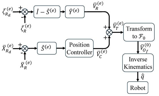
Figure 2.
A generic hybrid position/force control scheme for implementing admittance control about the RCM point.
In this block diagram, represents the desired resistance that the human operator should feel while backdriving the robot. This vector must be selected as zero vector for freely backdriving the robot about the RCM. augmented pose vector in which the first three elements define the RCM position relative to the base frame’s origin . For a generic case, this vector is composed as , which is conveniently defined first in the base frame and converted to the end-effector frame as follows: , where is a zero matrix. is the augmented measured position vector transformed into the end-effector frame as follows: . The “Position Controller” in the block diagram can be configured as any position control algorithm, including a simple proportional controller.
In the most general case (i.e., for a four-DoF RCM motion), the selection matrix is configured as follows to impose the RCM constraint through pure position control in translational motion along and axes.
If there is a requirement that the end-effector must not translate along -axis, then the third element in the diagonal of the matrix can be changed to 1. If the rotation about the -axis is not to be controlled through the moment input by the human operator, then the sixth element in the diagonal of the matrix can be changed to 1, and the last element of the and can include the rotation information about the -axis.
The resulting velocities through the admittance controller, , and the position controller, , are then superimposed to calculate the total velocity defined for the end-effector in the end-effector frame, .
The motion that is calculated in the end-effector frame must be converted to the velocity origin of the robot’s last frame in the base frame of the robot by using the generic calculation presented in (7).
Therefore, by (7), the calculation inside the block titled “Transform to ” is represented. Here, is the position vector that is defined from the RCM position to the origin of the last frame of the robot (e.g., for a six-DoF robot, this center is ). At the final step, one can choose to directly input the task-space velocities to the robot controller or use the inverse kinematics solution to calculate the subsequent required joint velocities. After this step, the built-in task-space or joint-space controller of the robot can be utilized to achieve the input motion.
The formulation described in this section does not depend on the robot architecture or the desired DoF for the RCM motion. However, to test and validate the formulation, a collaborative robot arm is used by defining a specific task, which is the handling of an endoscope. The next sections are reserved for the description of this case study and the validation of the formulation on this case study.
3. The Surgical Case Study: Definition of the Task and the Robot
The case study selected to verify the formulation of the hybrid control algorithm is a surgical robotic scenario. This section describes the task in which the proposed control framework is integrated to demonstrate its applicability with the help of a commercially available collaborative robot. The surgical robotic scenario is an endonasal operation in which endoscopic pituitary tumor surgery is carried out. In these operations, the surgical instrument called the endoscope is inserted through the patient’s nostril to visualize the sella turcica (surgery area), which is the skull area, and the place of the pituitary gland. The primary challenge surgeons face in such surgeries is that while one hand adjusts the position of the endoscope, the other hand can only hold one instrument. This constraint limits the movement capability of the surgeon. Furthermore, controlling the endoscope for 2–4 h (average duration of the surgery) may lead to fatigue, and eventually, this mitigates the efficiency of the operation. To tackle this challenge, assistants take the workload from the surgeon by holding the endoscope as a third hand (see Figure 3), allowing him/her to use both hands actively [23]. An alternative solution to this problem is to integrate a robot that holds and directs the endoscope based on the demands of the surgeon. The motion demand of the surgeon can be extracted by various ways, including speech recognition, joysticks, or image processing algorithms. The motion can be triggered with the help of a foot pedal and hence, the surgeon is able to perform the operation with both hands while supervising the robot. This is a surgeon–robot coexistence scenario.
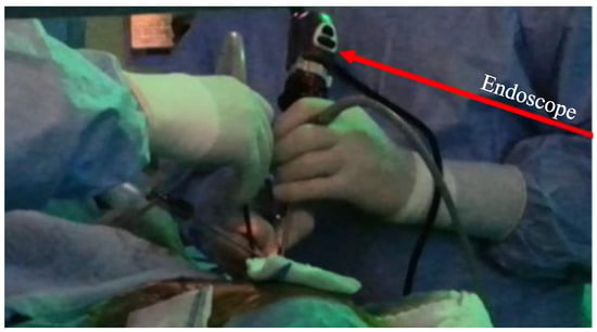
Figure 3.
Illustration of an endoscopic surgery conducted by the surgeon and assistant holding the endoscope.
As another option, the above-mentioned task can be carried out via the surgeon–robot physical interaction, which is the scenario we selected to show the performance of the proposed control framework in this paper. To clarify, instead of estimating the robots’ reference position through image processing, the surgeon moves the robot holding the endoscope to the target position and orientation by applying forces/moments on the endoscope. To achieve this, the hybrid control scheme proposed in this paper is implemented to generate the RCM of the end-effector, where the endoscope is attached, as a result of the surgeons’ forces/moments measured through a force/torque sensor assembled at the last link of the robot. The endonasal operations are minimally invasive endonasal surgeries in which the surgical instruments are moved about a pivot point that is the tip of the nose.
Throughout these surgeries, the surgeon performs RCM about the aforementioned pivot point by rotating the endoscope about three axes that are roll, pitch, yaw angles, and translation along the insertion direction to reach the pituitary gland or remove the endoscope after the operation. The roll angle, which is the rotation about the endoscope’s telescope axis, is necessary to maintain the surgical area view displayed on the monitor in the same orientation as presented in Figure 4.
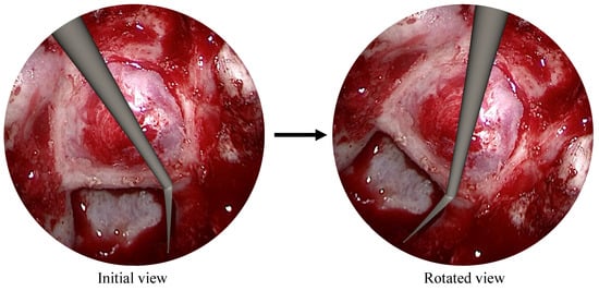
Figure 4.
Roll rotation illustration about the telescope axis.
In this case study, the Doosan A0509 collaborative robot (cobot) is incorporated into the system due to its relatively good repeatability value (0.03 mm). An endoscope holder is attached to its last link. The kinematic model of this robot is derived to define the RCM constraints and the motions, considering the constructional parameters of the endoscope holder.
The employed cobot is non-backdrivable in design, and thus a hybrid controller is implemented to let the surgeon adjust the endoscope view about the pivot point by exerting forces/moments to the cobot when it is necessary. As presented in Figure 5a, a force/torque (F/T) sensor is attached to the robot’s last flange to measure the surgeon’s interaction forces/moments applied on the endoscope.
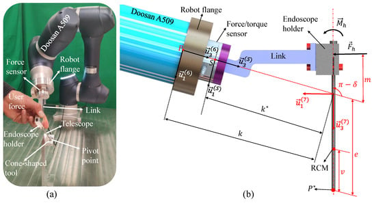
Figure 5.
The proposed control framework guarantees the RCM about the pivot point defined at the designed endoscope holder. An illustration of (a) the test bench and (b) the parameters and frames used to perform the hybrid controller for endonasal operations.
Afterward, the theoretical formulation of the hybrid controller is derived and reported in the next section using the parameters illustrated in Figure 5b to guarantee that the cobot is controlled about the pivot point under the surgeons’ guidance.
3.1. Cobot’s Kinematics Model
This section presents the kinematic models of the cobot through its Denavit–Hartenberg (DH) parameters in Table 1, which are developed utilizing the link lengths and the coordinate frames presented in Figure 6.

Table 1.
Denavit–Hartenberg parameters of the Doosan A0509 cobot.
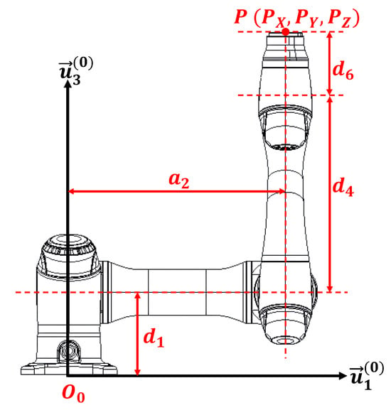
Figure 6.
The link parameters of the Doosan A0509 cobot without the endoscope holder.
3.1.1. Forward Kinematics Model
In this section, the forward kinematic equations of the cobot are presented to compute its tip point position and last link orientation with respect to the base frame. Also, is the exponential notation of the transformation matrix, representing the rotation of about the nth frame of the principal axis vector (). The transformation between (last link frame) and (base frame) is simplified to the following form:
where . The tip point position with respect to the base frame is computed in (9). Here, the tip point is indicated as the robot’s last frame center.
where is the identity matrix, and . In the next step, the general kinematics model of the cobot in (9) is modified by using the kinematic parameters of the endoscope holder. The orientation of the endoscope is calculated through a transformation matrix formulated with respect to the base frame in (10). Finally, the position of the endoscope’s tip point illustrated in Figure 5b with is computed in (11).
where denotes the rotation matrix indicating amount of rotation about ith axis.
3.1.2. Inverse Kinematics Model
After locating the endoscope inside the nostril (surgical area), the cobot is expected to perform RCM about a pivot point. A frame that is fixed to the endoscope can be defined as in which the is along the telescope axis of the endoscope. The angular motions about the RCM point are represented via target orientation angles , and and defined about , and , respectively. Also, translational motion along the RCM point is defined via the v parameter, as shown in Figure 5b, which is the distance between the RCM and the tip of the endoscope. Therefore, those four parameters are the input target reference values to perform RCM about a pivot point. The position of this pivot point and the orientation of the endoscope frame are calculated with respect to in (12) and (13), respectively.
After defining the input motion parameters, the position of the tip point of the robot () and its last link’s orientation are calculated as follows:
Since the result of (14) and (15) defines the motion of the robot’s tip point and its last frame, the robot can now be controlled using its built-in task-space controller or joint controllers. For the former one, the results of these two equations are directly sent to the task-space controller of the robot. For the latter, the inverse kinematics calculation should be carried out to compute the joint space motion to be tracked by the robot’s joint controllers. Inverse kinematic calculations are not presented here since it is not the main focus of this article.
4. Experiments and Results
The developed control framework is evaluated in a pituitary tumor surgery task on a test bench where a cone-shaped tool is fixed on a table together with the Doosan A0509 Cobot as in Figure 5a. The center of the smallest diameter of this cone is the pivot point at which the RCM is performed by the user’s input. In the design phase of this cone-shaped tool, first, 4 mm telescope is moved to its extreme orientation (i.e., and ), and translation (v) values at the pivot point in a computer-aided-design (CAD) software (SolidWorks 2022) while checking if there is a contact between the tool and the telescope. Next, a safety distance ( mm) is defined to tolerate the possible manufacturing errors between them, and finally, the minimum diameter of the tool is determined ( mm). The detailed views of this investigation in the CAD environment can be seen in Figure A4. The experiments were carried out at the Izmir Institute of Technology’s Robotics Lab and approved by the ethics committee of Izmir Institute of Technology’s Science and Engineering Department (Protocol No: E-41752998-050.04-2500051293).
The flowchart of the experiments is illustrated in Figure 7, and the parameters used in the experiments are presented in Table 2. First, the endoscope holder parameters, including , k, e, and m, are set in the hybrid controller formulation for calculating the user forcings at the RCM point (see Figure 5b). Then, the elements of the admittance and selection matrices are assigned depending on which direction the user will be allowed to backdrive the cobot. For instance, performing only orientation requires setting a non-zero value for in (3) and zero for the rest of them. On the other hand, all the elements of the selection matrix must be 1 except the fifth one, which has to be 0. In the experiments, first, only , , and v motions are carried out independently, and then combined movements such as and v and and v are carried out to demonstrate the performance of the hybrid controller.

Figure 7.
The proposed control method to achieve RCM motion about a pivot point via robot kinematics, and its own controller under the user force. HPs and LPs represent the holder parameters and link parameters, respectively. WLs denotes the workspace limits. Black arrows are the inputs, while red arrows indicate the flow of the control strategy.

Table 2.
Parameters of the experiments set based on the selected surgical case study.
After calculating the forces at the RCM point, the link parameters of the DOOSAN A0509 cobot are used in its kinematic models presented in (9) for implementing the hybrid contoller formulation. Throughout the experiments, the cobot is driven via its built-in joint space controller, and the motion demands are sent to the robot controller via the amovej command through ROS-1 (Robot Operating System) environment. To clarify, when the task-space velocities are generated in based on (5), they are taken as average velocity demands for a certain interval, which is the step size, and then multiplied by the step size time to calculate the corresponding displacements (i.e., angular and translational displacements) about the RCM point. Note that the angular displacement is reported in (13), whereas the translational displacement is written in (12). Then, an inverse kinematics formulation is used based on [24] to calculate the joint position demands to be entered in amovej command together with the step size of s. The large step size is due to the capabilities of the computer and the ROS-1 communication. Furthermore, the coordinates of the fixed pivot point ( and ), where the user performs RCM, are determined in based on the surgical robotics scenario. Also, workspace limits are assigned for , , and v to keep the endoscope holder in the surgical area while the user is handling it. Finally, an ATI force/torque sensor is attached to the last link of the robot to measure the user’s forcings and eventually to perform RCM until the task is accomplished, as shown in Figure 7. Throughout the experiments, the user is asked to move the endoscope holder deliberately from one pre-defined workspace limit to the other.
4.1. Experimental Protocol
Five experiments are conducted by assigning non-zero admittance terms (e.g., ) for enabling the motion along different RCM axes, and each experiment is repeated once. To begin with, in experiments-A, B, and C, admittance terms are set to enable only , , and v movements, respectively (see Table 2). Then, in experiment-D, v and are set to positive values in to carry out combined movements. Finally, in experiment-E, v and motions are performed while setting zero for the rest of the admittance terms. Regarding the elements of , they are assigned 0 along the directions where non-zero admittance terms are set to perform admittance control, as shown in Figure 2. Other elements are set to be 1 to constrain the holder movement along the corresponding directions under position control.
Furthermore, the elements of in Table 2 indicate the position and orientation values of the robot’s RCM point. If some axes are backdriven under admittance control, they are indicated as RCM variables (e.g., and v). On the other hand, the position/orientation of other axes is kept constant through the position controller, and their values are indicated with numbers in this table. For instance, in experiment-E, the and v combined movement is carried out under admittance control while keeping motion along the other axes constant (, , mm, and mm) using the robot’s built-in position controller.
4.2. Experimental Results
According to the experiment-A results presented in Figure 8, although the user applies forces and torques in all the directions, as expected, the consequent motion is only orientation change about . It is also clear that user is constrained between the upper ( in state-2) and lower ( in state-3) workspace limits as indicated in Table 2. The mean (± std) values of RCM constraint deviation in the and v values are reported as () and mm ( mm), respectively. The latter is computed by taking the mean and standard deviation presented in Figure 8 as it represents the task-space position deviation resolved in along . Also, the mean values (± std) of and are computed to be mm ( mm) and mm ( mm), respectively. The range of these values verifies that the proposed hybrid controller guides the user along the enabled RCM axes (i.e., only in this case) while constraining his/her motion along the rest of the directions.
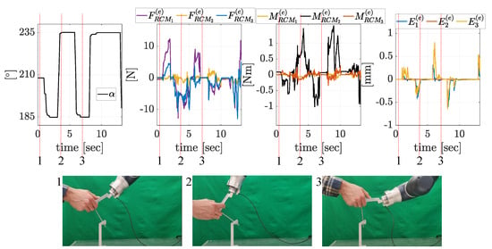
Figure 8.
Experiment-A results where only movement is conducted. Red dashed lines with the 1, 2, 3 numbers denote the state of the experiments, and pictures show the configuration of the robot at that instant of time. is in state-1, in state-2, and in state-3. and represent the force and torque resolved at the RCM point. where denotes the Cartesian position error at the RCM point along , , and , respectively.
Regarding the experiment-E results illustrated in Figure 9, resultant motions under the user forcings are v and in compliance with the assigned admittance terms for those two RCM axes. Furthermore, while is moved between (state-4) and (state-3), v is moved between 100 mm (state-1) and mm (state-2). This shows that defined workspace limits keep the user inside the surgical area. Moreover, there are minimal deviations from the set constant orientation throughout the experiment, and the mean deviation (± std) is recorded as (). In addition, the mean values (± std) of the task-space position error along , , and are recorded as mm ( mm), mm ( mm), and mm ( mm), respectively. These results indicate that the user is allowed to perform combined and v movements under admittance control, and the rest of the motions are restricted, which shows the effectiveness of the formulation.
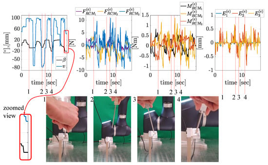
Figure 9.
Experiment-E results where and v combine movement is conducted. Red dashed lines with the 1, 2, 3, 4 numbers denote the state of the experiments, and pictures show the configuration of the robot at that instant of time. /v is /100 mm in state-1, −/−78 mm in state-2, /−8 mm in state-3, and −/36 mm in state-4. and represent the force and torque values resolved at the RCM point. where denotes the Cartesian position error at the RCM point along , , and , respectively.
In addition, the experiment-B, C, and D results are presented in Appendix A. For instance, only the admittance term corresponding to rotation was a positive term during the experiment presented in Figure A1, whereas in Figure A2 only the v RCM axis is allowed to be backdriven under the user force. Additionally, the combined motion results when the and v motions are allowed are illustrated in Figure A3. These results serve as additional justifications that the developed hybrid control framework is able to let the user move the endoscope along the RCM axes in which non-zero admittance terms are identified in (see Table 2). When it comes to motion along the other axes that are constrained utilizing the built-in robot position controller, the mean values (± std) of , , and are mm ( mm), mm ( mm), and mm ( mm) in experiment-B, mm ( mm), mm ( mm), and mm ( mm) in experiment-C, mm ( mm), mm ( mm), and mm ( mm) in experiment-D. Finally, the mean of the set constant value is () in experiment-B, the mean values of the set constant and values are () and () in experiment-C, and the mean of the set constant value is () in experiment-D. These reported constant orientation values are the constant elements that are presented in Table 2 (for instance, in experiment-B, the value is fixed at ).
Moreover, the zoomed view is presented in Figure 9 to demonstrate the instant when the user releases the endoscope. It is clear that no unstable movement is monitored. The same situation can be seen also in Figure A1 and Figure A2. When the forces and moments are close to zero at the end of the experiment (i.e., physical interaction is lost between the user and the endoscope), the robot maintains its final position.
5. Discussions
The section serves as a discussion of the other relevant aspects of the study. For instance, the user forces and moments applied during the experiments are analyzed to compare it with the reported values in the literature. In [15], hand-guiding is conducted in an MIS task, and the user forces change between N. When it comes to our experiments results, we detected the maximum user force and moments measured throughout the experiments as follows: the mean values (± std) of maximum forces/moments along , , and are recorded as N ( N)/ Nm ( Nm) in experiment-A, N ( N)/ Nm ( Nm) in experiment-B, N ( N)/ Nm ( Nm) in experiment-C, N ( N)/ Nm ( Nm) in experiment-D, and N ( N)/ Nm ( Nm) in experiment-E. It is clear that our results match the benchmark information on user forces/moments in [15].
It is also important to note that the applied user forcings are directly related to the assigned admittance terms, and the focus of this work is not to achieve the task within a predefined force/torque or a velocity range. For instance, by identifying larger admittance terms than the current ones, the same resultant motions can be achieved with smaller user forcings (user forces/torques are multiplied by the admittance terms to generate motions as in (5)). Selecting the suitable admittance term in the human–robot interaction is very personal and thus must be selected and tuned through user experiments. Depending on the level of motion precision and, contradicting to it, the level of user effort, experimental studies can be carried out to quantitatively measure these aspects (i.e., the motion precision and user effort) and qualitatively receive the user feedback on user preferences through questionnaires. Although these user experiments can be initially conducted on phantoms, for surgical systems, cadavers are included as the next setup as ex vivo experimentations, which is followed by in vivo experiments with the actual patients. These next steps of the experiments are the subjects of future studies. Neverthless, we compared our results with [15] to emphasize that the developed hybrid controller can be exploited in an MIS task without a long calibration season to determine suitable admittance terms, unlike in [12], in which the calibration seasons are carried out for the selection of admittance terms.
Related to the task-space position error maintaining the RCM point, the maximum values of , , and are mm, mm, and mm in experiment-A, mm, mm, and mm in experiment-B, mm, mm, and mm in experiment-C, mm, mm, and mm in experiment-D, and mm, mm, and mm in experiment-E. The main cause of these errors is the step size limitation of the experimental system. Until a new force–torque measurement is received in the next time step, the robot is moved with the amovej command, which fits a spline between the two consecutive positions of the joints. When the sampling time is small, the errors caused by the fitted spline become also small. In a previous benchmark study reported in [5], the RCM error is measured to be above 1 mm. In another study [2], this error is reported to be mm. This concludes that our control framework produces better results in terms of deviations from the RCM constraint during the admittance control of surgical robots compared to the recently published studies. In addition, according to the anthropomorphic dimensions of human nose, the mean (± std) Nares width of female North Europeans is mm ( mm), whereas for female West Africans, it is mm ( mm). The former is the smallest dimension among the populations, while the latter is the greatest based on [25]. Considering the smallest one, and dividing it to two, mm is obtained as the incision port diameter. In our experimental setup, the smallest diameter of the cone-shaped tool is mm. Therefore, the difference justifies that the RCM error is within the tolerance of real surgical use.
Furthermore, the current large step size also limits the speed of the operation. The surgeon needs to put more effort in moving the endoscope with a large step size since admittance gains should be limited due to safety reasons. On the other hand, higher admittance gains can be assigned when a smaller sampling size is set (i.e., sampling frequency must be higher), and eventually faster motions can be carried out under the same effort of the surgeon. Also, the calculation of the force–torque vector at the end-effector assumes that the RCM point is always maintained perfectly. However, due to the beforementioned sampling time issues, in the current experimental setup, there is a small deviation from the RCM point. Therefore, with an industrial setup that has higher sampling frequency capacity, more dynamic motions of the endoscope can be achieved with the small effort of the surgeon, and force–torque calculation errors can be made smaller, even negligible. It should be noted that this limitation in the implementation is not imposed by the proposed formulation.
6. Conclusions
In this article, a hybrid controller consisting of pure position and admittance controllers is developed to perform RCM about a pivot point in compliance with the user-induced forces/moments. The essential novelty of our study is that the controller formulation is defined at the RCM point. Depending on the task, desired RCM constraints are implemented using the robot’s built-in position controller, while the motions in other directions are achieved as the user backdrives the robot via the admittance controller. This strategy is accomplished by configuring selection and admittance matrices in the formulation complying with the task requirements. We carried out five experiments, setting different admittance terms in different axis to conduct independent (e.g., only ), and combined (e.g., only and v) movements via the admittance controller about the RCM point. The results show that the maximum of the mean (± std) task-space position errors in maintaining the RCM point along , , and axes in overall five experiments is mm ( mm). The main cause of this error is the sampling step size of the system, and it can be reduced by setting a smaller step size. However, considering the studies in the literature on control-based RCM in MIS, our validation tests produced better results compared to the others.
As a future study, we will enhance the hybrid controller to investigate what happens when the surgeon needs to retract the endoscope holder from the pivot point, for instance, to clean the camera. In this situation, the constraint conditions need to change. This change has to be managed not to result in sudden changes in the motion. These tests will be conducted on a cadaver in the operational environment.
Author Contributions
Conceptualization, M.İ.C.D.; methodology, M.İ.C.D.; software, M.F.D.; validation, E.M., M.F.D., and M.İ.C.D.; formal analysis, M.İ.C.D. and E.M.; investigation, M.F.D., E.M., and M.İ.C.D.; resources, M.İ.C.D.; data curation, E.M. and M.F.D.; writing—original draft preparation, M.İ.C.D. and E.M.; writing—review and editing, M.İ.C.D. and E.M.; visualization, M.İ.C.D. and E.M.; supervision, M.İ.C.D.; project administration, M.İ.C.D.; funding acquisition, M.İ.C.D. All authors have read and agreed to the published version of the manuscript.
Funding
This research was funded by the Scientific and Technological Research Council of Türkiye (TUBITAK) via grant number 123M353.
Data Availability Statement
Data will be available upon request.
Acknowledgments
During the preparation of this manuscript/study, we thank Oğuz Güler and Mehmet Alp Balkan for their contributions. The authors have reviewed and edited the output and take full responsibility for the content of this publication.
Conflicts of Interest
The authors declare no conflicts of interest.
Appendix A
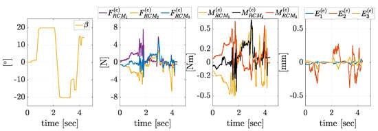
Figure A1.
Experiment-B results where only movement is conducted. and represent the force and torque values resolved at the RCM point. where denotes the Cartesian position error at the RCM point along , , and , respectively.
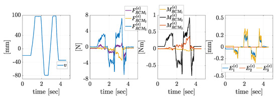
Figure A2.
Experiment-C results where only v movement is conducted. and represent the force and torque values resolved at the RCM point. where denotes the Cartesian position error at the RCM point along , , and , respectively.

Figure A3.
Experiment-D results where and v combine movement is conducted. and represent the force and torque values resolved at the RCM point. where denotes the Cartesian position error at the RCM point along , , and , respectively.
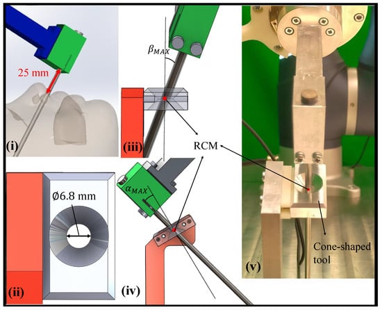
Figure A4.
Detailed view of the experimental setup where a cone-shaped tool is fixed on a table together with the DOOSAN cobot. The illustration of (i) minimum distance between the nose and the endoscope holder, (ii) minimum cone diameter from top view, (iii) robot configuration at from front view, (iv) from side view, and (v) zoomed view of the fabricated experimental setup.
References
- Yaşır, A.; Kiper, G.; Dede, M.C. Kinematic design of a non-parasitic 2R1T parallel mechanism with remote center of motion to be used in minimally invasive surgery applications. Mech. Mach. Theory 2020, 153, 104013. [Google Scholar] [CrossRef]
- Kastritsi, T.; Doulgeri, Z. A passive admittance controller to enforce remote center of motion and tool spatial constraints with application in hands-on surgical procedures. Robot. Auton. Syst. 2022, 152, 104073. [Google Scholar] [CrossRef]
- Zhu, K.; Nguyen, C.C.; Sharma, B.; Phan, P.T.; Hoang, T.T.; Davies, J.; Ji, A.; Nicotra, E.; Wan, J.; Pruscino, P.; et al. Development of a Bioinspired Soft Robotic System for Teleoperated Endoscopic Surgery. Cyborg Bionic Syst. 2025, 6, 0289. [Google Scholar] [CrossRef] [PubMed]
- Pugin, F.; Bucher, P.; Morel, P. History of robotic surgery: From AESOP® and ZEUS® to da Vinci®. J. Visc. Surg. 2011, 148, e3–e8. [Google Scholar] [CrossRef] [PubMed]
- Su, H.; Qi, W.; Chen, J.; Zhang, D. Fuzzy Approximation-Based Task-Space Control of Robot Manipulators With Remote Center of Motion Constraint. IEEE Trans. Fuzzy Syst. 2022, 30, 1564–1573. [Google Scholar] [CrossRef]
- Davila, A.; Colan, J.; Hasegawa, Y. Voice control interface for surgical robot assistants. In Proceedings of the 2024 International Symposium on Micro-NanoMehatronics and Human Science (MHS), Nagoya, Japan, 22–24 November 2024; pp. 1–5. [Google Scholar]
- Paul, R.A.; Jawad, L.; Shankar, A.; Majumdar, M.; Herrick-Thomason, T.; Pandya, A. Evaluation of a Voice-Enabled Autonomous Camera Control System for the da Vinci Surgical Robot. Robotics 2024, 13, 10. [Google Scholar] [CrossRef]
- Uslu, T.; Gezgin, E.; Özbek, S.; Güzin, D.; Can, F.C.; Çetin, L. Utilization of low cost motion capture cameras for virtual navigation procedures: Performance evaluation for surgical navigation. Measurement 2021, 181, 109624. [Google Scholar] [CrossRef]
- Karnam, M.; Cattin, P.C.; Rauter, G.; Gerig, N. Qualitative and quantitative assessment of admittance controllers for hand-guiding surgical robots. at-Automatisierungstechnik 2023, 71, 515–527. [Google Scholar] [CrossRef]
- Melo, J.; Sánchez, E.; Díaz, I. Adaptive admittance control to generate real-time assistive fixtures for a cobot in transpedicular fixation surgery. In Proceedings of the 2012 4th IEEE Ras & Embs International Conference on Biomedical Robotics and Biomechatronics (Biorob), Rome, Italy, 24–27 June 2012; pp. 1170–1175. [Google Scholar]
- Hu, P.; Sun, T.; Wang, Z.; Mosetlhe, T.; Zhang, L. Model predictive admittance control of knee arthroplasty surgical robot. In Proceedings of the 2024 39th Youth Academic Annual Conference of Chinese Association of Automation (YAC), Dalian, China, 7–9 June 2024; pp. 1–7. [Google Scholar] [CrossRef]
- Fontúrbel, C.; Cisnal, A.; Fraile-Marinero, J.C.; Pérez-Turiel, J. Force-based control strategy for a collaborative robotic camera holder in laparoscopic surgery using pivoting motion. Front. Robot. AI 2023, 10, 1145265. [Google Scholar] [CrossRef] [PubMed]
- Kastritsi, T.; Doulgeri, Z. Human-guided desired rcm constraint manipulation with applications in robotic surgery: A torque level control approach. In Proceedings of the 2020 European Control Conference (ECC), St. Petersburg, Russia, 12–15 May 2020; pp. 1448–1453. [Google Scholar]
- Deal, A.; Chow, D.L.; Newman, W. Hybrid natural admittance control for laparoscopic surgery. In Proceedings of the 2012 IEEE/RSJ International Conference on Intelligent Robots and Systems, Vilamoura-Algarve, Portugal, 7–12 October 2012; pp. 1277–1283. [Google Scholar]
- Kastritsi, T.; Doulgeri, Z. A Controller to Impose a RCM for Hands-on Robotic-Assisted Minimally Invasive Surgery. IEEE Trans. Med Robot. Bionics 2021, 3, 392–401. [Google Scholar] [CrossRef]
- Balkan, M.A.; Dede, M.İ.C. Formulation of Admittance Control of a Surgical Robot About Remote Center of Motion. In Proceedings of the International Workshop on Medical and Service Robots, Poitiers, France, 2–4 July 2025; Springer: Berlin/Heidelberg, Germany, 2025; pp. 438–447. [Google Scholar]
- Sharkawy, A.N.; Koustoumpardis, P.N. Human–robot interaction: A review and analysis on variable admittance control, safety, and perspectives. Machines 2022, 10, 591. [Google Scholar] [CrossRef]
- Lin, M.; Wang, H.; Yang, C.; Liu, W.; Niu, J.; Vladareanu, L. Human–Robot Cooperative Strength Training Based on Robust Admittance Control Strategy. Sensors 2022, 22, 7746. [Google Scholar] [CrossRef] [PubMed]
- Wang, Y.; Yang, Y.; Zhao, B.; Qi, X.; Hu, Y.; Li, B.; Sun, L.; Zhang, L.; Meng, M.Q.H. Variable admittance control based on trajectory prediction of human hand motion for physical human-robot interaction. Appl. Sci. 2021, 11, 5651. [Google Scholar] [CrossRef]
- Hu, X.; Liu, G.; Ren, P.; Jia, B.; Liang, Y.; Li, L.; Duan, S. An Admittance Parameter Optimization Method Based on Reinforcement Learning for Robot Force Control. Actuators 2024, 13, 354. [Google Scholar] [CrossRef]
- Sirintuna, D.; Aydin, Y.; Caldiran, O.; Tokatli, O.; Patoglu, V.; Basdogan, C. A variable-fractional order admittance controller for pHRI. In Proceedings of the 2020 IEEE International Conference on Robotics and Automation (ICRA), Paris, France, 31 May–31 August 2020; pp. 10162–10168. [Google Scholar]
- Raibert, M.H.; Craig, J.J. Hybrid position/force control of manipulators. J. Dyn. Syst. Meas. Control 1981, 103, 126–133. [Google Scholar] [CrossRef]
- Dede, M.İ.C.; Kiper, G.; Ayav, T.; Özdemirel, B.; Tatlıcıoğlu, E.; Hanalioglu, S.; Işıkay, İ.; Berker, M. Human–robot interfaces of the NeuRoboScope: A minimally invasive endoscopic pituitary tumor surgery robotic assistance system. J. Med. Devices 2021, 15, 011106. [Google Scholar] [CrossRef]
- Balkan, T.; Özgören, M.K.; Arıkan, M.S.; Baykurt, H.M. A method of inverse kinematics solution including singular and multiple configurations for a class of robotic manipulators. Mech. Mach. Theory 2000, 35, 1221–1237. [Google Scholar] [CrossRef]
- Zaidi, A.A.; Mattern, B.C.; Claes, P.; McEcoy, B.; Hughes, C.; Shriver, M.D. Investigating the case of human nose shape and climate adaptation. PLoS Genet. 2017, 13, e1006616. [Google Scholar] [CrossRef] [PubMed]
Disclaimer/Publisher’s Note: The statements, opinions and data contained in all publications are solely those of the individual author(s) and contributor(s) and not of MDPI and/or the editor(s). MDPI and/or the editor(s) disclaim responsibility for any injury to people or property resulting from any ideas, methods, instructions or products referred to in the content. |
© 2025 by the authors. Licensee MDPI, Basel, Switzerland. This article is an open access article distributed under the terms and conditions of the Creative Commons Attribution (CC BY) license (https://creativecommons.org/licenses/by/4.0/).