Abstract
This study aims to provide a set of experimentally determined forces needed for gripping operations related to a robotically manipulated microliter manual pipette. The experiments are conducted within the scope of automated sample processing for polymerase chain reaction (PCR) analysis in small-sized to medium-sized laboratories where dedicated automated equipment is absent and where procedures are carried out manually. Automation is justified by the requirement for increased efficiency and to eliminate possible errors generated by lab technicians. The test system comprises an industrial robot; a dedicated custom gripper assembly necessary for the pipette; pipetting tips; and mechanical holders for tubes with chemical substances and genetic material. The selected approach is to measure forces using the robot’s built-in force–torque sensor while controlling and limiting the pipette’s gripping force and the robot’s pushing force. Because the manipulation of different materials requires the attachment and discarding of tips to and from the pipette, the operator’s perceived tip release force is also considered.
1. Introduction
Basic information about polymerase chain reaction (PCR) is as follows.
Starting with the pandemic year of 2020, a substantial body of medical analysis involved using deoxyribonucleic acid (DNA) for different diagnostics. The samples taken directly from patients contain a small amount of DNA, and the PCR technique developed in the 1980s requires large amounts of high-purity DNA [1]. Using PCR, a very large number of copies can be obtained from a portion of a DNA molecule in only a few steps. These comprise the following: genomic DNA extraction, PCR amplification of the gene fragment containing the mutation, the enzymatic digestion of the PCR product, and the electrophoretic separation and visualization of fragments. The final diagnosis is established after enzymatic digestion.
The protocol for DNA extraction implies the repeated pipetting of small quantities into Eppendorf elution tubes for many hours a day. For this reason, and also due to current laboratory operations, improving the manual procedure is desirable (Figure 1a). In Figure 1b, the PCR thermocycler used in the final step of the test can be observed after the other operations were manually executed by the analysis laboratory personnel, e.g., centrifugation, incubation, and extraction.
Figure 1.
Current manual samples processing (a) and polymerase chain reaction (PCR) thermocycler (b).
This method is currently used in the biochemistry laboratory of the Victor Babes University of Medicine, Timisoara (RO), and the authors are hoping to automate the process for optimization and efficiency. It is also appealing to eliminate the errors made by tired lab technicians by reducing the time needed for manual pipetting and the manipulation of small quantities, in addition to avoiding contamination.
During workdays, the operators must stay concentrated and maintain focused attention for long periods of time, and this can lead to undesired analysis results.
Automated PCR analysis provides several advantages over the manual procedure. The accuracy and efficiency of PCRs can be enhanced by automated systems, such as thermal cyclers, and by using PCR robots. The studies reveal that starting with the 2020 global crisis, after the outbreak of COVID-19, artificial intelligence (AI) algorithms have contributed by improving the detectability of the virus via polymerase chain reactions and subsequently comparing the results of chest tomography scans with the clinical symptoms of patients, anamnesis, and laboratory tests. The rapid diagnosis of COVID-19-positive patients became possible [2]. Currently, AI is a branch of engineering that can resolve complex challenges, and there is continuous progress in the development of software programming [3].
In modern medical laboratories, automated machinery is used for testing samples [4] at different automation levels [5]. Since this area is developing, robotic services for laboratories should be further improved [6,7]. Automation allows for reactions to be performed in an easier manner, resulting in significant precision and time savings [8]. A related study was carried out on automation programs for the picking and placing of small objects [9]. The use of artificial intelligence in the medical field [10], the effects and benefits of automation processes [11], and the use of compliant systems for grasp optimization [12] are being studied, all resulting in minimal operator intervention, improved productivity, increased safety in the laboratory, minimized errors [13], and the saving of time [14]. There are also studies on new levels of artificial intelligence, the integration of large language models (such as ChatGPT) into healthcare [15], the use of computer vision for health monitoring [16], human–robot interactions [17], the optimization of workspace design [18], and error correction and calibration for maximizing robot precision [19].
The following characteristics should also be considered when choosing automation devices: manipulator performance [20,21], using different types of grippers [22], the use of 3D printed parts [23], and combining a pipette with a gripper [24]. There are also studies on space optimization and kinematic analysis [25,26], sensors used to control operations [27], and different types of components in medical laboratories [28].
A study of these components used a description and comparison of the grippers’ ability to pick up objects of different types, as employed in many industrial and medical applications, both in known and unknown environments and for different types of material [29]. The choice of this study’s gripper model, as well as the final 3D-printed model for the finger clamps, took into account mechanical problems [30,31,32] and other studies related to the materials and the movements of the end effector [33].
For future studies, other smart sensors should be considered, which can be integrated to perform the automation of samples in the laboratory [34].
The problem identified, for which the current study proposes an automated sub-process, is the necessity to create a system for the appropriate manipulation of a manual pipette in the presence of laboratory analysis components.
The result is situated and addresses scenarios taking place in a medium-sized medical university laboratory, and it focuses on the robotic gripping and manipulation of a standard manual pipette.
The broader objectives of this study are to improve operations in a medical laboratory that currently does not have any type of automated system for sample processing and is working only with the equipment presented in previous studies [35,36]. Because improvements in the activity of the lab personnel and faster performance in the processing of PCR tests are desired, the proposed solution must be suitable in the lab’s existing space while using all equipment currently present in the laboratory.
For this purpose, the authors performed two experiments. The first was carried out to design gripping components and to establish the appropriate forces for clamping the pipette. The second was carried out to establish the necessary force with which dispensing tips can always be attached to the end of the pipette. For a correct and efficient working methodology, the manipulation forces must be constant, in addition to the positioning of the pipette relative to the other devices used (such as tip holders, reagent holders, etc.).
2. Materials and Methods
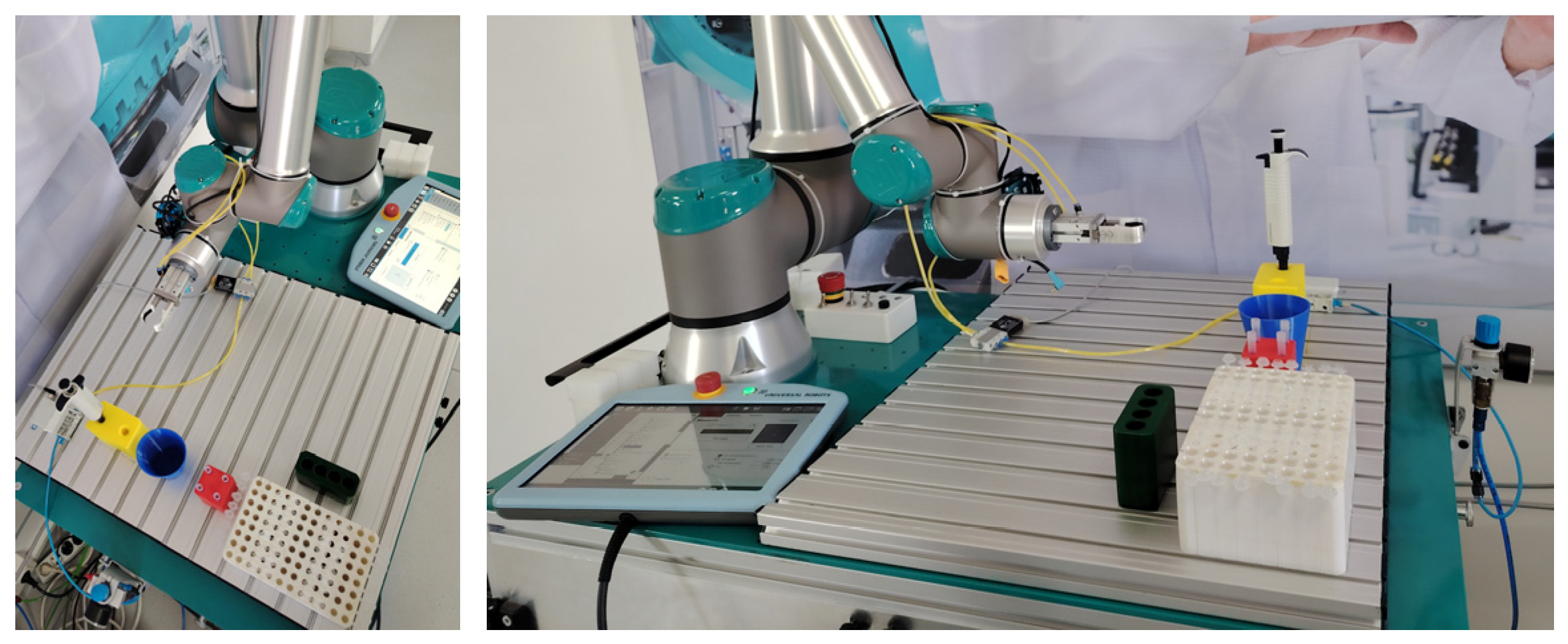
2.1. Robotic Testing Work Cell
The laboratory testing work cell is based on a Universal Robots UR10e collaborative robot [37] (Odense, Denmark), which is available in one of our robotics labs. The pipette used in the experiments is a single-channel, 1000 µL fixed-type pipette [38]. Standard tips were used for each subsequent sample measurement. Figure 2 shows the top and front views of the experimental work cell.
Figure 2.
Top and front view of the robotic work cell used for testing.
The trajectories of the robot within the work area of the robot and the singularity issues that can possibly occur during the automated program were described in previous studies [35,36].
2.2. Three-Dimensional Modeling of the Components for the Experimental Setup
The components were designed and used as an assembly for sample preparation during analyses with the PCR technique. This assembly consists of the following:
- A holder for the manipulated pipette;
- A holder with multiple locations for the tips;
- support for tubes with reagents;
- A holder for the elution tubes;
- A recycling cup for discarded tips;
- A gripper assembly for manipulating the pipette.
The design of the above components was carried out considering their use in small and medium laboratories that have limited space available. Moreover, the entire system of holders and supports was conceived such that the assembly and disassembly can be quickly and easily carried out; moreover, the robot can also access any needed chemicals in a logical manner [35].
Figure 3 presents the 3D designs of the components, which were modeled and optimized according to multiple criteria such as overall dimensions, occupied area, process function, and tolerances.
Figure 3.
Three-dimensional models of support containers: (a) sample support, (b) primer support, (c) pipette support, and (d) tip support.
The parts were manufactured via fused deposition modeling (FDM) 3D printing using polylactic acid (PLA)—a widespread type of filament. An electro-pneumatic setup was devised to test the functionality of the components and to validate the designed models.
3. Determining the Pipette’s Proper Clamping Force
3.1. Defining of Clamping Force
The proposed system consists of a robotic arm, some standard industrial components, printed components, a manual pipette, disposable tips, elution tubes, and reagent tubes. The process plan is to carry the pipette to specified locations, where it must collect a tip that will be fed with chemical substances, or it must discard the tip. The movements are imposed by the robot’s program. For each chemical substance, the pipette uses another tip, which must be properly attached to the pipetting head. After each use, the tip is discarded into the recycling cup/bin.
The automated pipette must be clamped by the gripper with enough force around its body because the tips, which are small conical containers, must be obtained via friction resulting from an insertion (pushing) force. This trajectory falls along the Z-axis (Figure 4a), and the theoretical determination of the vertical Z-travel force limit on the pipette (FZmax) is obtained by relating it to a conical shrink fit model (Figure 4b), where values of the insertion distance l and the angle α are known.
Figure 4.
Process of attaching the tip to the pipette: (a) inserting process and (b) theoretical model for a conical shrink-fit assembly [36].
However, the main unknowns are represented by the contact between the pipette’s end and tip collar. The friction coefficient here is unknown, and it is also difficult to estimate. Another consideration for the tip is the plastic deformation of its thin walls. The material characteristics of the pipette and the tip are not specified by the producer, nor are the machining tolerances, which is impractical for the purpose of the theoretical determination of forces [36].
The goal of this experimental study is to obtain the force values necessary to hold the clamped pipette and the values necessary to push-fit the tips; this is required in order to realize a functional and well-performing system without the risk of leaking reagents.
Moreover, the exerted forces must not damage the pipette or the tips, and proper tip discarding must occur. The final aspect relates to collision cases, which must not damage the components or pose an injury threat to the lab technicians inadvertently present in the robot’s workspace.
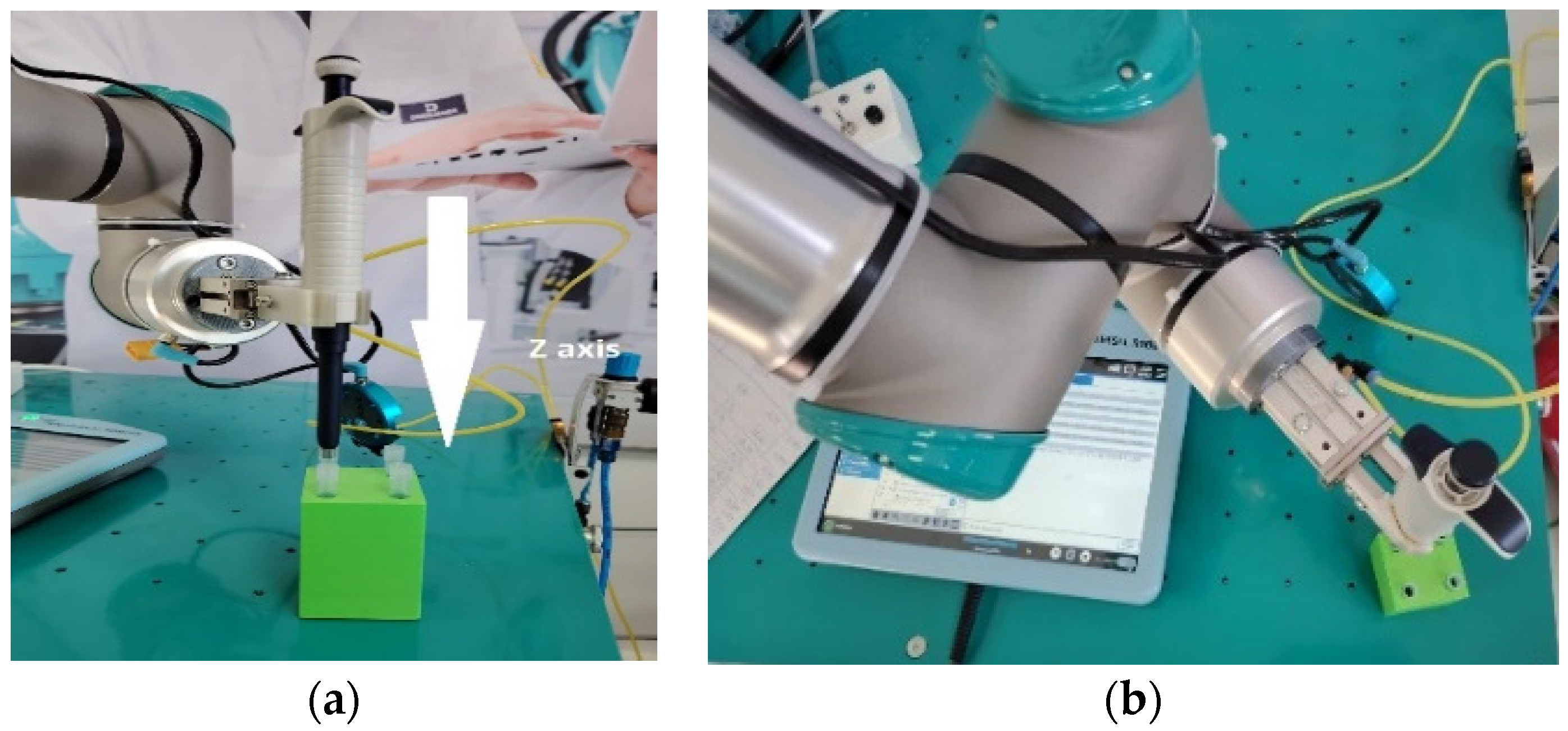
3.2. Test Setup for Measuring Forces
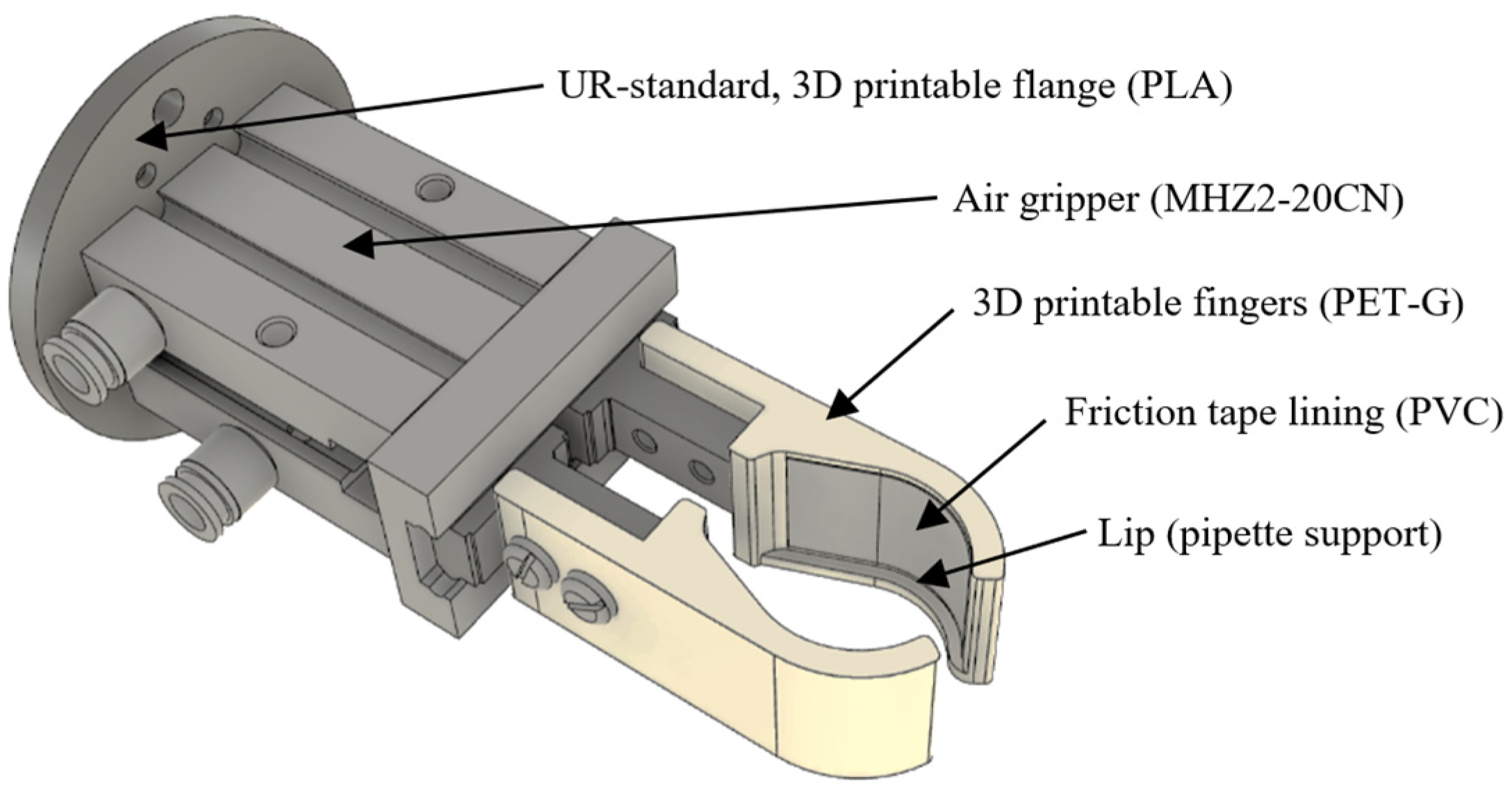
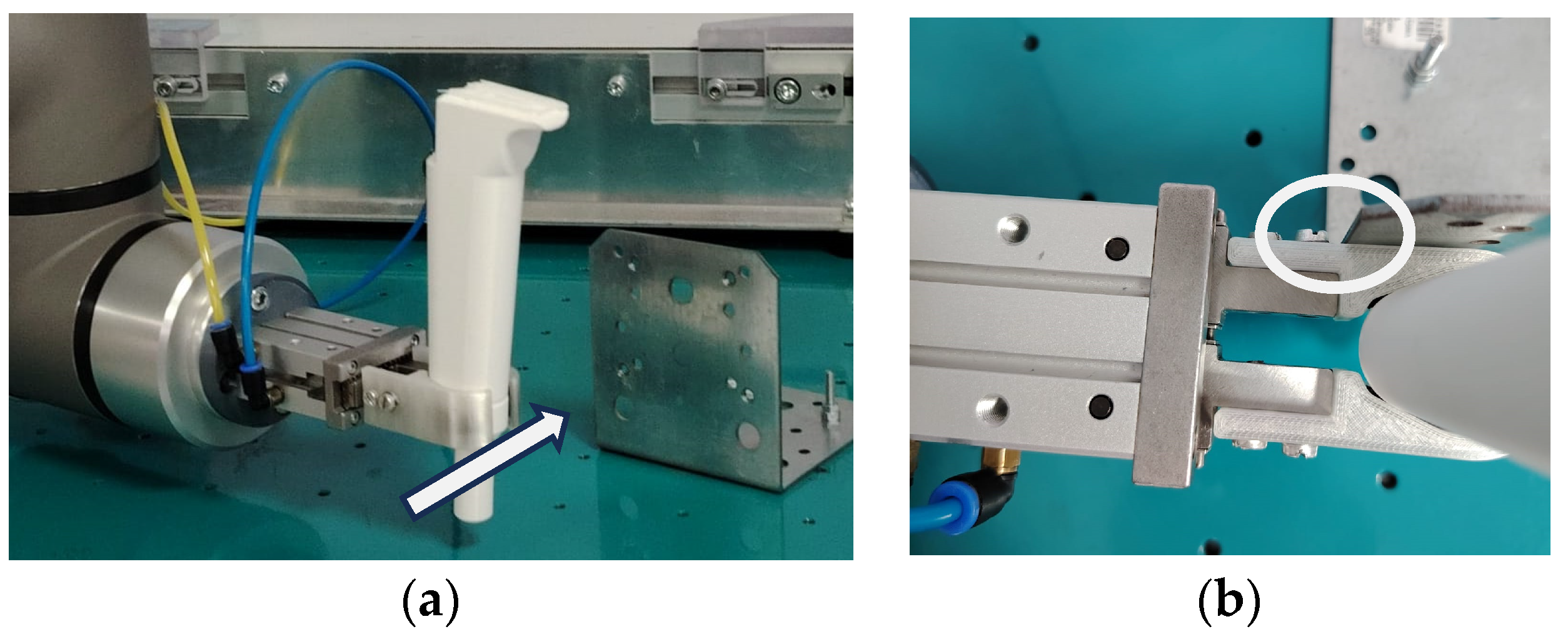
The experiment uses the force–torque sensor available in the robot’s 6-axis flange. The robot was programmed for slow vertical motion while recording the tool center point (TCP) vertical force and position. For the pipette’s holding force experiment, the pipette was pushed against a rigid horizontal surface. For the tip collection experiment, the pipette was pushed against tips that were previously inserted vertically into their collection support.
The measurement process is controlled by the operator for each sample, imposing or limiting forces. Figure 5 shows a test stand setup for attaching the tips.
Figure 5.
Testing force method for attaching tips: (a) front view with relevant Z axis and (b) top view.
3.3. Gripper Design
Because the pipette used in the experiments is a regular manual pipette, a custom gripping device was designed for the robot in order to be able to manipulate the pipette efficiently and safely. While operating the robot, the pipette needs to be firmly gripped, but it can also be subjected to a variety of damage forces; thus, several operating and safety conditions need to be considered for the design of the gripping tool:
- –
- The pipette must be gripped in the same position and orientation every time.
- –
- The pipette holding force must be appropriate for the operation to be carried out.
- –
- Excessive forces from any direction (but especially from Z-travel—the work direction) must be avoided by quickly releasing the pipette.
- –
- The pipette must remain in a gripped state (low force) upon the failure or shut-off of compressed air components.
- –
- Supplemental future mechanisms for operating the pipette must be accounted for.
To comply with the above statements, we need to use a gripper that can exert enough force to hold the pipette, this force needs to be controlled continuously or in steps, and the gripper should have suitable finger travel and be able to exert closing forces while not being actuated. Other studies also designed pipette gripers with different stages of gripping forces [39,40]. The most suitable off-the-shelf solution is to use an industrial air gripper that is normally closed (NC) and spring-loaded [41]. A convenient method of controlling the gripping force for this air gripper is to have its opening and closing pressure controlled using an electronic pressure regulator [42].
For this device, a tool flange adapter conforming to ISO 9409-1-50-4-M6 [43] was designed and 3D printed to affix it to the robot. Also, a set of fingers/clamps was designed and 3D printed for the pipette. The assembly model is presented in Figure 6.
Figure 6.
Pipette 3D clamp model attached to the air gripper.
The clamp’s design follows the sectional profile of the pipette body in order to auto-orient the pipette upon closing. They are also designed with a protruding lip in the lower part such that the pipette can be positioned in the same vertical position upon lifting with a soft-closed gripper. These clamps were printed using a glycol-modified polyethylene terephthalate (PET-G) filament due to its better mechanical properties, but this material provides almost no friction when in contact with the pipette’s plastic body; thus, lining tape was installed in order to increase friction levels. This is needed because vertical forces are applied to the pipette when collecting the tip in order to stop the pipette from sliding out of the clamps. A small side effect of the lining tape is the increase in the lateral compliance of the pipette during operations.
The vertical Z-travel force limit relative to the pipette (FZmax) is directly related to the gripping force, and it can be adjusted as required (from the robot program). An initial empirical value was selected at 35 N after manually using the pipette and communicating with trained lab personnel.
The lateral forces acting on the gripper were not evaluated during the robot’s positioning. Thus, a lateral hard collision test was conducted, imposing a linear trajectory on the gripper’s clamps beyond a fixed metal plate—with v = 3 m/s and a = 10 m/s2—while using a 3D-printed pipette mock-up (Figure 7a). The highest recorded force on the relevant axis was 274 N. Since the robot stopped before any structural damage could be observed with respect to the clamps in the collaborative mode (Figure 7b), after such a collision, the pipette was inspected and reseated properly in the gripper.
Figure 7.
Testing the lateral hard collision of the gripper. (a) Collision trajectory (arrow) and (b) contact/hit point with the metal plate (encircled).
Figure 8 presents the assembled robot gripper and the actual gripped pipette ready for experimentation.
Figure 8.
Robot assembly: gripper only (left); gripped pipette (right).
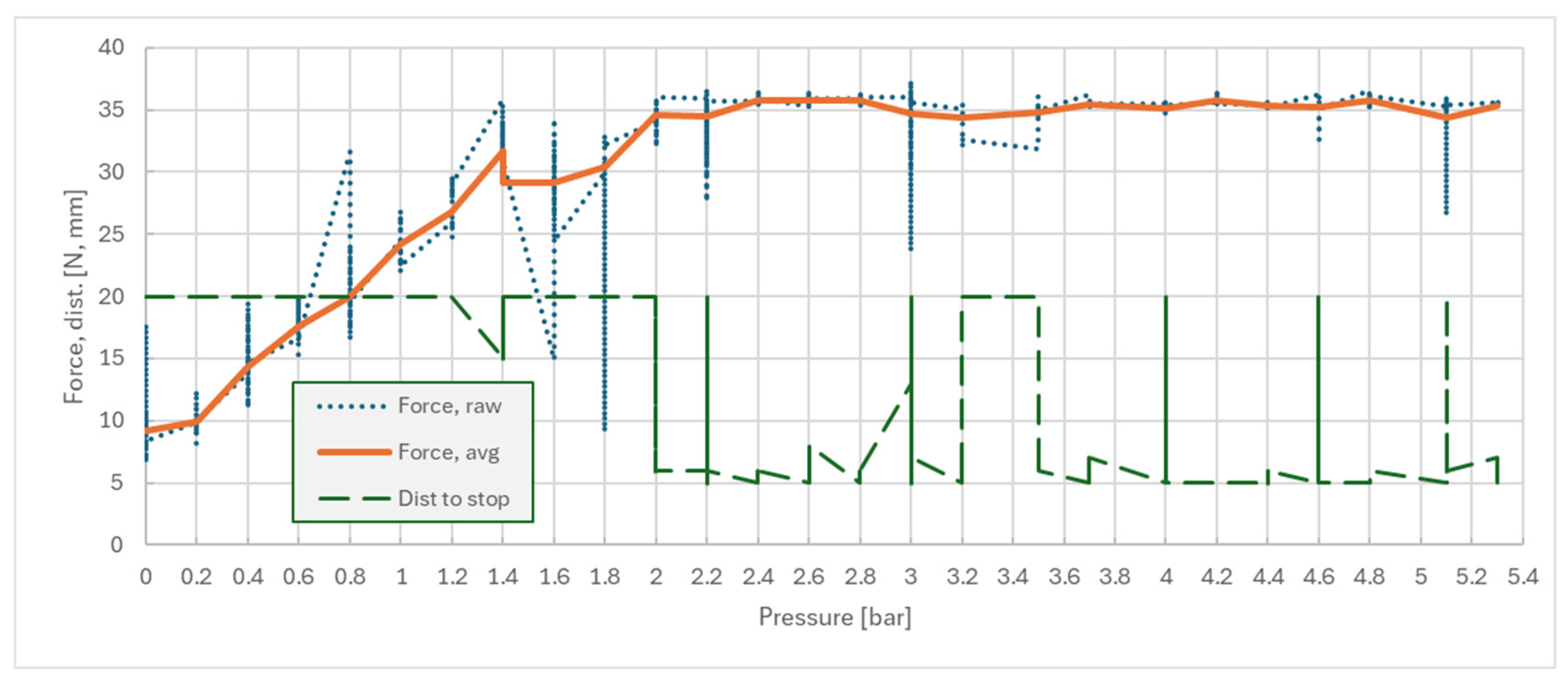
3.4. First Experiment—Pipette Holding Force
For the automated process proposed in this study, the gripper must be actuated by the robot controller; thus, all required pneumatic and electric components are interconnected, as shown in Figure 9.
Figure 9.
Electric (a) and pneumatic (b) schematics.
The pneumatic schematic in Figure 9b presents the pressure that was supplied by a compressed air source (a mobile compressor) and that was passed through an air service unit, where it was filtered and limited to five bar. The compressed air then entered the electrically controlled proportional pressure regulator Y0. The regular has an internal pressure feedback sensor that also delivers an analog signal, and it is presented as B0. The pressure-controlled air then enters a directional control solenoid valve Y1, which is used for directing the flow to open or close gripper Grp.
To command and control the electrical devices from the robot program, signals must be connected to the robot’s input/output (IO) interface. Table 1 provides the signals and functions for all the elements as they appear in Figure 9a.
Table 1.
Pipette gripper command and control items.
A flowchart of the robot program is presented in Figure 10 for the sake of simplifying explanations regarding concurrent robot actions and also for easier program reproducibility. Force measurements and stop decisions are carried out in a separate thread; thus, user input, output control, and motion tasks run in parallel with force measurement and data-sending tasks.
Figure 10.
Robot program flowchart for the first experiment.
Since we do not have a transfer function that links the operating air pressure to the normal force inflicted on the pipette’s body and we also do not know the friction coefficients involved, we must experimentally determine this process parameter by testing the full pressure range against the recorded vertical (Z-travel) force applied onto the pipette.
For the first part of the experiment—determining the gripping pressure for maximum vertical pipette force—the workflow comprises programming the robot to grip and push the pipette at 20 mm against a rigid surface with a constant velocity of 10 mm/s. The vertical pushing force is measured via the robot’s force–torque sensor, and it is internally offset by the TCP and the parametrization of the payload’s center of gravity. The maximum force during a push is then recorded and compared with the maximum imposed limit (FZmax = 35 N), in addition to the pressure detected in the gripper.
First Experiment—Results
Following the experimental workflow, a pressure step interval of 0.2 bar was selected and used, and the test routine was launched using switch S1. For every pressure setpoint, n = 10 samples were measured, and the average force FZ was considered. The results are presented in Figure 11; combining the raw recorded force, the robot’s average force and traveled distance were measured until it stopped. Abnormal values were kept for reference. Supporting raw data for both experiments is available in Supplementary Materials [SM]. One can observe that pressures higher than 2.2 bar resulted in stoppage due to the force limit (FZ ≥ 35 N), with an average stopping distance of 5 mm. This distance is the combined result of system compliance with respect to robot stopping time.
Figure 11.
Pipette hold/slip force/pressure dependency—with friction tape.
Testing the forces without friction lining tape on the gripper clamps confirmed the inability of the system to hold the pipette—with an average value of FZ = 4.3 N; the results are presented in Figure 12. The measuring method is the same (n = 5 samples), but the pressure intervals were set at 0.5 bar.
Figure 12.
Pipette slip force/pressure dependency—without friction tape.
This information is also useful in the robot’s final application program as it can detect faulty pipette gripping during the tip attachment phase and, consequently, a warning message can be raised.
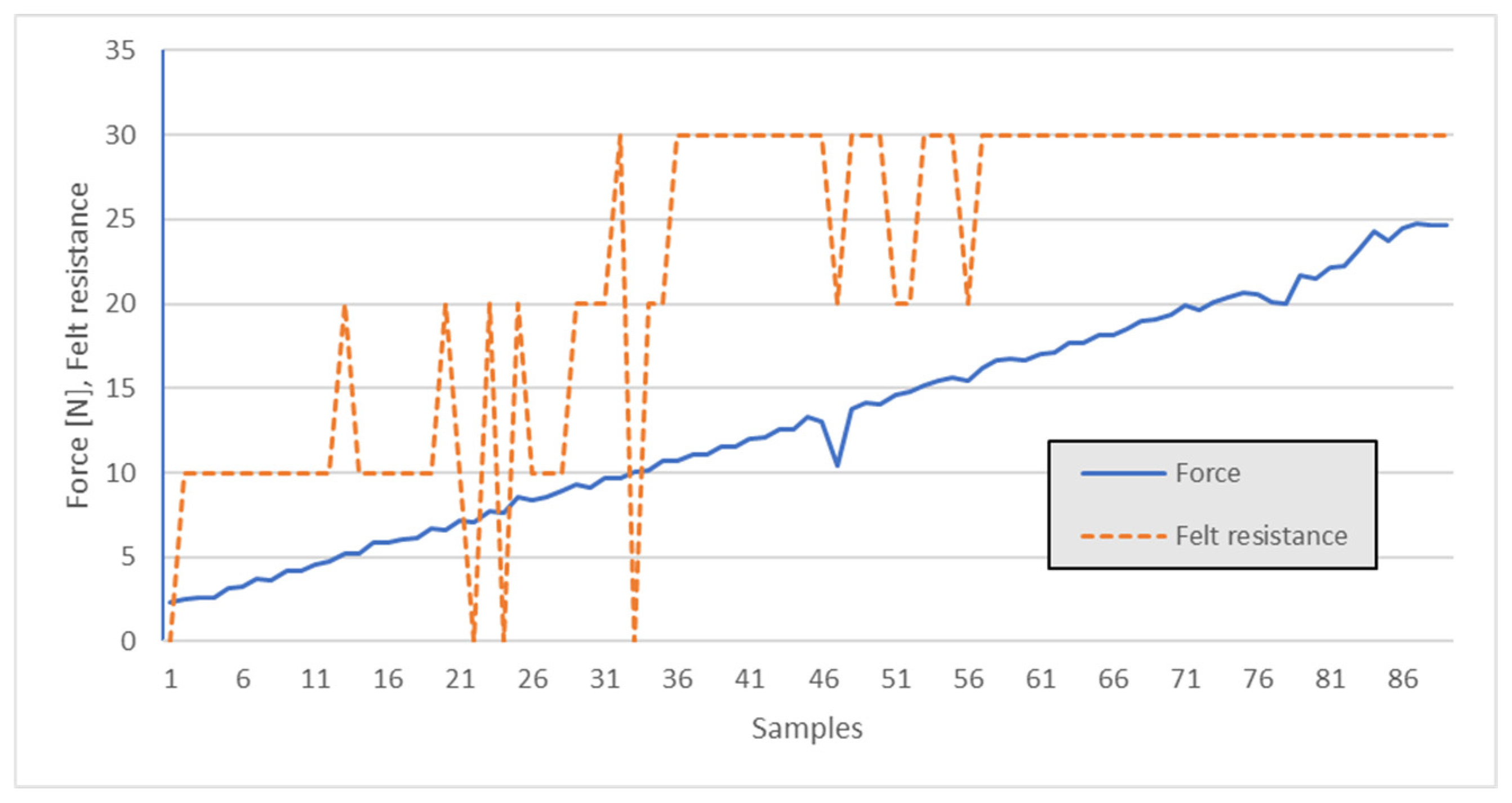
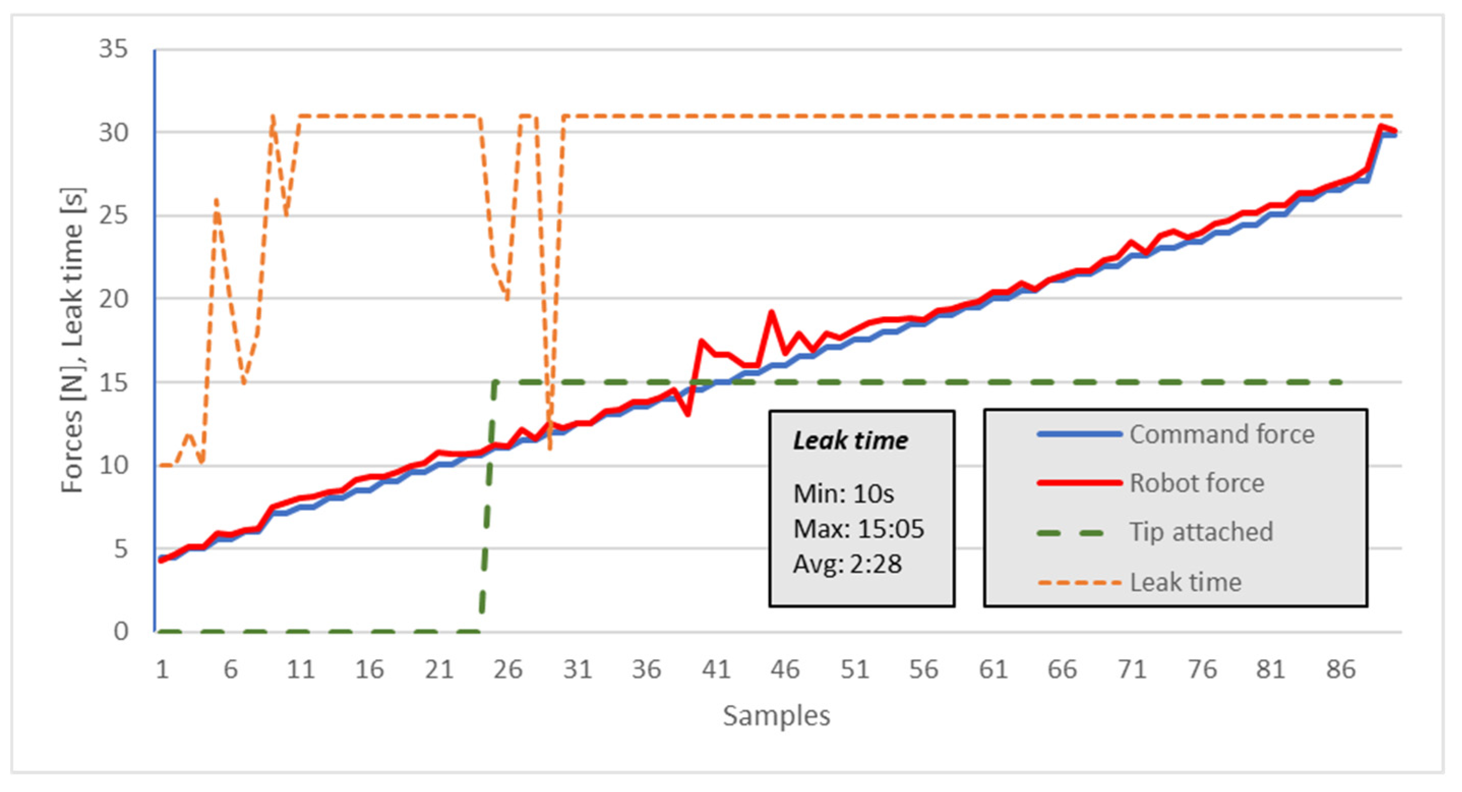
3.5. Second Experiment—Tip Holding Force
Apart from the pipette gripping force, for the final application, we also need to be able to collect tips with the pipette.
In order to determine the suitable force interval for picking up tips, the experiment is conducted in a similar manner to the one for the pipette holding force. The idea is to find a convenient pressing force into the tip (optimal experimental force) such that several events are concurrent during the process:
- –
- The tip must remain attached to the pipette after lifting and positioning the assembly.
- –
- The tip must not leak any of its collected (water) content for at least 30 s.
- –
- The tip must be released by pressing the dedicated pipette button, with an ergonomically accepted finger force of 10–25 N.
- –
- The tip must not crack or deform at its assembly collar or at its narrow open end.
- –
- The tip should be reusable for at least one more operation under the same conditions (although this will never happen in the lab as the tips are disposable, it is a qualitative indicator of the mechanical stress applied to the tip).
The workflow is similar to the other experiment, but this time, the variable metric is the force exerted by the pipette when pushing into the tip, and this is manually controlled for each sample using the potentiometer P0 (similar to the previous pressure). The outcome is both a quantitative time measurement of the period until the tip starts leaking, and it is also a qualitative measure of how easy it is to release the tip by pushing the pipette’s dedicated button.
The robot program was modified to advance (for no more than 10 mm) with the same speed of 10 mm/s until the set pushing force was attained. Upon meeting this threshold, the robot should switch the direction of motion, raise the pipette with the tip attached, and be ready for pipetting.
Second Experiment—Results
For the tip holding resistance, the test tips were placed in their holding case and then placed under the vertical pipette (which was gripped by the robot). The commanded force interval was set to 1 N starting from 2 N (the robot’s minimum readout). The maximum test force was limited to 25 N. The outcome referred to the perceived (felt) resistance when pushing the tip’s release button. Numerical values were attributed to the qualitative impressions, as shown in Table 2.
Table 2.
Tip ejecting force—qualitative to quantitative conversion.
The graphical dependence relation is depicted in Figure 13.
Figure 13.
Manual tip ejecting force—user qualitative impression.
From the figure’s data, one can observe that under 10 N, attachment failure relative to the tips was likely, i.e., where “Felt resistance” falls to zero. Thus, further experiments should concentrate on push-fit forces above 10 N.
For the leak test, the tips were placed in their holding case, and after tip collection, a manual pipetting step was employed using water. The commanded force interval was set to 1 N starting from 2 N (the robot’s minimum readout). The maximum test force was limited to 30 N. If the force is higher than that, the pipette could easily slide from the gripper—refer to experiment 1. A time limit of 30 s was set as the maximum waiting time for observing a leak (but leak times were fully recorded, with a maximum of over 15 min). For a good pick-up operation, no leak should occur if the operation is quicker than 15 s—the time needed for the robot to move and dispense contents. A period of less than 10 s was considered a failure, and this only occurred for FZ < 10 N.
The measured force was also recorded. The results are presented in Figure 14 and Table 3. The outcome referred to the gripper still being attached (Figure 14—graph value 15) or unattached (Figure 14—graph value 0), and it referred to the time (s) until the tip started leaking. It can be observed that when the pushing force FZ is >15 N, there is no leak in the first 30 s.
Figure 14.
Tip leak time versus pipette (robot) push-fit force.
Table 3.
Leak time sample success as a function of the push-fit force.
After measuring leak times, the tips were discarded, and new tips were used for each subsequent sample measurement.
4. Discussion and Future Work
For the first experiment, after data analysis, we decided that a gripper pressure setpoint between 2.5 and 3.5 bar is appropriate for the correct clamping of the pipette. Lower pressures could result in pipette slippage from the gripper during the tip attachment operation. Higher pressures do not inflict any harm, but they are also unnecessary. In the final application, the pressure could also be set up from a manual pressure regulator, releasing the proportional electronic pressure regulator for other duties.
For the second experiment, following the data presented in Figure 13 and Figure 14 and combined with the findings in the first experiment, the recommended pipette pushing force interval for picking up and sealing the tip (for proper attachment) is [15…25] N. In the final lab application, the robot should be initially set to exert (i.e., —to stop pushing at) a force of 20 N, followed by on-site tuning.
The main advantage of the proposed solution is as follows: the use of readily available mainstream industrial components that allow for quick and cost-effective system replication for laboratories that need some type of pipetting process automation. Another notable point is that several manual pipettes can be used during the process, which are gripped and manipulated in sequence; each of them is set to a specific dispensing volume. Although not detailed in this study, it must be noted that the reagents and sample volumes to be dispensed during PCR analyses are different for each (reagent/sample) type. Another advantage is the easy setup process of the robot’s end effector and the safe pneumatic actuation nature; thus, lab personnel can easily adapt to working with the assembly.
There are also some disadvantages regarding the system’s flexibility. The system cannot be easily repurposed to perform another robotic job—except if using a robot tool changer. Moreover, the system is not very fault-tolerant; in its current state, it cannot detect the loss of a pipette or incorrect pipette gripping orientations, nor can it detect failed tip attachment (provided that the pushing force is still correct). However, some of these aspects can be mitigated in future studies.
The principal problems encountered during the experiments’ development were related to the optimum height of the gripper clamps, as there were some initially unforeseen limitations. Since the mechanism for actuating the pipette’s knobs is not yet designed, this results in maximum vertical travel clearance while picking up the pipette, which can be imposed in a later stage. It is possible that the authors will have to adapt the gripper clamps in another design iteration.
At its current state, robotic experimental applications cannot execute pipetting, dispensing, and tip-discarding sub-processes. These operations require the actuation of the pipette’s dedicated knobs. Continuation of the present study entails the development of the actuation mechanism and the control of the entire end-to-end pipetting process. We plan to follow a similar approach by using only pneumatic actuation, combined with remote pneumatic sensing, such that no electric/electronic components are present beyond the robot’s flange. In total, three pneumatic actuators will be used for the entire pipetting device (the gripper for the pipette and two additional cylinders for the knobs). The pneumatic control scheme will be optimized for the minimum tube lines, concurrently providing the same functionality as when manually working with the pipette. Theoretical analyses of the gripping and dispensing assembly will be conducted via a top-down approach. Robot trajectory optimizations can also be considered in future studies, but these are only worth pursuing when robot automation is utilized in a lab as a final application.
5. Conclusions
The experimental study confirmed the functionality of the designed components and validated the approach and developed 3D models.
An appropriate pressure setpoint in the gripper was found for the correct clamping of the pipette. The testing gripper clamps without friction lining tape confirmed the inability of the system to hold a pipette.
The push-fit force for the pipette during the attachment of tips to the end of the pipette was defined within a specific interval. This ensures that the tips are not leaking (correctly attached) while also allowing for appropriate tip release (discarding) force. The upper interval force limit is also imposed by the requirement that the pipette cannot slide upwards in the gripper when attaching the tip.
The presented experimental setup is part of a wider project that aims to realize the automated handling of samples during an automated PCR analysis, and it is dedicated to improving the process in a manually operated medical analysis laboratory.
This article is a revised and expanded version of the manuscript entitled “Experimental Approach on the Force for Robotic Pipetting in Automated PCR (Polymerase Chain Reaction)”, which was presented at MEDER2024—Mechanism Design for Robotics, Timișoara, Romania, 26–28 June 2024.
Supplementary Materials
The following supporting information can be downloaded at: https://www.mdpi.com/article/10.3390/robotics14010002/s1, Figure 1, Figure 2, Figure 3, Figure 4, Figure 5, Figure 6, Figure 7, Figure 8, Figure 9, Figure 10, Figure 11, Figure 12, Figure 13 and Figure 14; Data supporting Figure 11, Figure 12, Figure 13 and Figure 14.
Author Contributions
Conceptualization, M.-O.S. and V.C.; methodology, V.C.; software, V.C. and R.K.; validation, C.-M.G. and C.S.; formal analysis, M.-O.S.; investigation, M.-O.S.; resources, E.-G.T.; data curation, C.S.; writing—original draft preparation, M.-O.S. and V. C.; writing—review and editing, V.C.; visualization, C.S. and E.-G.T.; supervision, C.-M.G.; project administration, C.-M.G.; funding acquisition, R.K. All authors have read and agreed to the published version of the manuscript.
Funding
This research received no external funding. The APC was funded by Politehnica University of Timisoara, 300006, Timisoara, Romania.
Data Availability Statement
Data available in Supplemental Materials.
Conflicts of Interest
The authors declare no conflicts of interest.
References
- Worsfold, P.; Townshend, A.; Poole, C. (Eds.) Encyclopedia of Analytical Science; Elsevier Ltd.: Amsterdam, The Netherlands, 2005. [Google Scholar]
- Mei, X.; Lee, H.C.; Diao, K.Y.; Huang, M.; Lin, B.; Liu, C.; Xie, Z.; Ma, Y.; Robson, P.M.; Chung, M.; et al. Artificial intelligence-enabled rapid diagnosis of patients with COVID-19. Nat. Med. 2020, 26, 1224–1228. [Google Scholar] [CrossRef]
- Hamet, P.; Tremblay, J. Artificial intelligence in medicine. Metabolism 2017, 69 (Suppl.), S36–S40. [Google Scholar] [CrossRef]
- Available online: https://www.genome.gov/genetics-glossary/DNA-Replication (accessed on 4 November 2024).
- Yang, K.; Gan, Y.; Cao, Y.; Yang, J.; Wu, Z. Optimization of 3D Tolerance Design Based on Cost-Quality-Sensitivity Analysis to the Deviation Domain. Automation 2023, 4, 123–150. [Google Scholar] [CrossRef]
- Martínez, D.S.; Carlos, A.J.; Gomez-Donoso, F. A new automatic method for demoulding plastic parts using an intelligent robotic system. Int. J. Adv. Manuf. Technol. 2023, 129, 3109–3121. [Google Scholar] [CrossRef]
- Erebak, S.; Kasimoğlu, N. Nurses’ Robot Use Self-Efficacy: Mediation Effect in The Relationship Between Robot Anxiety and Preference of Automation Levels. J. Ege Univ. Nurs. Fac. 2024, 40, 47–56. [Google Scholar] [CrossRef]
- Tatsumi, N.; Okuda, K.; Tsuda, I. A new direction in automated laboratory testing in Japan: Five years of experience with total laboratory automation system management. Clin. Chim. Acta 1999, 290, 93–108. [Google Scholar] [CrossRef]
- Andrade, M.A.B.; Ramos, T.S.; Adamowski, J.C.; Marzo, A. Contactless pick-and-place of millimetric objects using inverted near-field acoustic levitation. Appl. Phys. Lett. 2020, 116, 054104. [Google Scholar] [CrossRef]
- Jiang, L.; Wu, Z.; Xu, X.; Zhan, Y.; Jin, X.; Wang, L.; Qiu, Y. Opportunities and challenges of artificial intelligence in the medical field: Current application, emerging problems, and problem-solving strategies. J. Int. Med. Res. 2021, 49, 03000605211000157. [Google Scholar] [CrossRef]
- Holland, L.L.; Smith, L.L.; Blick, K.E. Total laboratory automation can help eliminate the laboratory as a factor in emergency department length of stay. Am. J. Clin. Pathol. 2006, 125, 765–770. [Google Scholar] [CrossRef]
- Zhu, Z.; Liu, Y.; Ju, J.; Lu, E. Design and Experimental Test of Rope-Driven Force Sensing Flexible Gripper. Sensors 2024, 24, 6407. [Google Scholar] [CrossRef] [PubMed]
- Scimmi, L.S.; Melchiorre, M.; Troise, M.; Mauro, S.; Pastorelli, S. A Practical and Effective Layout for a Safe Human-Robot Collaborative Assembly Task. Appl. Sci. 2021, 11, 1763. [Google Scholar] [CrossRef]
- Seaberg, R.S.; Stallone, R.O.; Statland, B.E. The role of total laboratory automation in a consolidated laboratory network. Clin. Chem. 2000, 46, 751–756. [Google Scholar] [CrossRef] [PubMed]
- Neha, F.; Bhati, D.; Shukla, D.K.; Amiruzzaman, M. ChatGPT: Transforming Healthcare with AI. AI 2024, 5, 2618–2650. [Google Scholar] [CrossRef]
- Ferraris, C.; Amprimo, G.; Pettiti, G. Computer Vision and Image Processing in Structural Health Monitoring: Overview of Recent Applications. Signals 2023, 4, 539–574. [Google Scholar] [CrossRef]
- Anil Al, G.; Estrela, P.; Martinez-Hernandez, U. Towards an intuitive human-robot interaction. In Proceedings of the 2020 IEEE International Conference on Multisensor Fusion and Integration for Intelligent Systems (MFI), Virtual Conference, 14–16 September 2020. [Google Scholar]
- Kucuk, S.; Bingul, Z. Robot workspace optimization basedon a novel local and global performance index. In Proceedings of the IEEE International Symposium on Industrial Electronics, ISIE, Dubrovnik, Croatia, 20–23 June 2005; pp. 1593–1598. [Google Scholar]
- Asif, S.; Webb, P. Realtime Calibration of an Industrial Robot. Appl. Syst. Innov. 2022, 5, 96. [Google Scholar] [CrossRef]
- Sarosh, P.; Tarek, S. Manipulator Performance Measures—A Comprehesive Literature Survey. J. Intell. Robot Syst. 2015, 77, 547–570. [Google Scholar] [CrossRef]
- Kot, T.; Bobovský, Z.; Vysocký, A.; Krys, V.; Šafarík, J.; Ružarovský, R. Method for Robot Manipulator Joint Wear Reduction by Finding the Optimal Robot Placement in a Robotic Cell. Appl. Sci. 2021, 11, 5398. [Google Scholar] [CrossRef]
- Jiang, P.; Oaki, J.; Ishihara, Y.; Ooga, J. Multiple-Object Grasping Using a Multiple-Suction-Cup Vacuum Gripper in Cluttered Scenes. Robotics 2024, 13, 85. [Google Scholar] [CrossRef]
- Bezzini, R.; Bassani, G.; Avizzano, C.A.; Filippeschi, A. Design and Experimental Evaluation of Multiple 3D-Printed Reduction Gearboxes for Wearable Exoskeletons. Robotics 2024, 13, 168. [Google Scholar] [CrossRef]
- Zhang, J.; Wan, W.; Tanaka, N.; Fujita, M.; Takahashi, K.; Harada, K. Integrating a Pipette Into a Robot Manipulator With Uncalibrated Vision and TCP for Liquid Handling. IEEE Trans. Autom. Sci. Eng. 2024, 21, 5503–5522. [Google Scholar] [CrossRef]
- Shah, J.A.; Saleh, J.H.; Hoffman, J.A. Review and Synthesis of Considerations in Architecting Heterogeneous Teams of Humans and Robots for Optimal Space Exploration. IEEE Trans. Syst. MAN Cybern. Part C Appl. Rev. 2007, 37, 779–793. [Google Scholar] [CrossRef]
- Filippeschi, P.; Griffa, C.; Avizzano, A. Kinematic Optimization for the Design of a Collaborative Robot End-Effector for Tele-Echography. Robotics 2021, 10, 8. [Google Scholar] [CrossRef]
- Florian, D.C.; Odziomek, M.; Ock1, C.L.; Chen, H.; Guelcher, S.A. Principles of computer controlled linear motion applied to an open source afordable liquid handler for automated micropipetting. Sci. Rep. 2020, 10, 13663. [Google Scholar] [CrossRef]
- Trudeau, M.; Skinner, N. Demonstration of LC-MS Nitrosamine Impurity Quantification Performance Using Automated Sample Preparation with the Andrew+ Pipetting Robot; 720007134; Waters Corporation: Milford MA, USA, 2021. [Google Scholar]
- Tai, K.; El-Sayed, A.R.; Shahriari, M.; Biglarbegian, M.; Mahmud, S. State of the Art Robotic Grippers and Applications. Robotics 2016, 5, 11. [Google Scholar] [CrossRef]
- Fantoni, G.; Santochi, M.; Dini, G.; Tracht, K.; Scholz-Reiter, B.; Fleischer, J.; Lien, T.K.; Seliger, G.; Reinhart, G.; Franke, J.; et al. Grasping devices and methods in automated production processes. CIRP Ann. Manuf. Technol. 2014, 63, 679–701. [Google Scholar] [CrossRef]
- Jin, H.L.; Delgado-Martinez, I.; Chen, H.Y. Customizable Soft Pneumatic Chamber-Gripper Devices for Delicate Surgical Manipulation. J. Med. Devices 2014, 8, 044504. [Google Scholar]
- Chelpanov, I.B.; Kolpashnikov, S.N. Problems with the mechanics of industrial robot grippers. Mech. Mach. Theory 1983, 18, 295–299. [Google Scholar] [CrossRef]
- Rateni, R.; Cianchetti, M.; Ciuti, G.; Menciassi, A.; Laschi, C. Design and Development of a soft robotic gripper for manipulation in minimally invasive surgery: A proof of concept. Meccanica 2015, 50, 2855–2863. [Google Scholar] [CrossRef]
- Bosse, S.; Hogreve, S.; Tracht, K. Design of a Mechanical Gripper with an Integrated Smart Sensor Network for Multi-Axial Force Sensing and Perception of Environment. In Proceedings of the Smart Systems Integration Conference, Zürich, Switzerland, 21–22 March 2012. [Google Scholar]
- Sandu, M.O.; Gruescu, C.M.; Lovasz, E.C.; Ciupe, V. Synthesis of an Automation System for the PCR (Polymerase Chain Reaction) Samples Preparation Process. In Proceedings of SYROM 2022 & ROBOTICS 2022: 13th IFToMM International Symposium on Science of Mechanisms and Machines & XXV International Conference on Robotics; Book Series Mechanism and Machine Science; Spinger: Cham, Switzerland, 2022; Volume 127, pp. 389–396. [Google Scholar]
- Sandu, M.O.; Gruescu, C.M.; Kristof, R.; Sticlaru, C.; Ciupe, V.; Lovasz, E.C. Experimental Approach on the Force for Robotic Pipetting in Automated PCR (Polymerase Chain Reaction). In Mechanism Design for Robotics. MEDER 2024. Mechanisms and Machine Science; Lovasz, E.C., Ceccarelli, M., Ciupe, V., Eds.; Springer: Cham, Switzerland, 2024; Volume 166. [Google Scholar] [CrossRef]
- Available online: https://www.universal-robots.com/ro/produse/robot-ur10e/ (accessed on 4 November 2024).
- Available online: https://www.witeg.de/en/products/liquid-handling/pipetting/microliter-pipettes/microliter-pipettes-witopet-economy-fix-single-channel?number=5401910 (accessed on 4 November 2024).
- Fleischer, H.; Drews, R.R.; Janson, J.; Reddy, B.; Patlolla, C.; Chu, X.; Klos, M.; Thurow, K. Application of a Dual-Arm Robot in Complex Sample Preparation and Measurement Processes. J. Lab. Autom. 2016, 21, 671–681. [Google Scholar] [CrossRef]
- Ellwood, R.; Raatz, A.; Hesselbach, J. Vision and Force Sensing to Decrease Assembly Uncertainty. In Precision Assembly Technologies and Systems; Springer: Berlin/Heidelberg, Germany, 2010; pp. 123–130. [Google Scholar]
- Available online: https://www.smcpneumatics.com/MHZ2-20CN.html (accessed on 4 November 2024).
- Available online: https://www.festo.com/ro/ro/a/8046299/ (accessed on 4 November 2024).
- International Standard ISO 9409-1, Manipulating industrial robots–Mechanical interfaces–Part 1: Plates. Available online: https://cdn.standards.iteh.ai/samples/36578/348a837664f444bc83e2902c7a5acf4c/ISO-9409-1-2004.pdf (accessed on 4 November 2024).
Disclaimer/Publisher’s Note: The statements, opinions and data contained in all publications are solely those of the individual author(s) and contributor(s) and not of MDPI and/or the editor(s). MDPI and/or the editor(s) disclaim responsibility for any injury to people or property resulting from any ideas, methods, instructions or products referred to in the content. |
© 2024 by the authors. Licensee MDPI, Basel, Switzerland. This article is an open access article distributed under the terms and conditions of the Creative Commons Attribution (CC BY) license (https://creativecommons.org/licenses/by/4.0/).