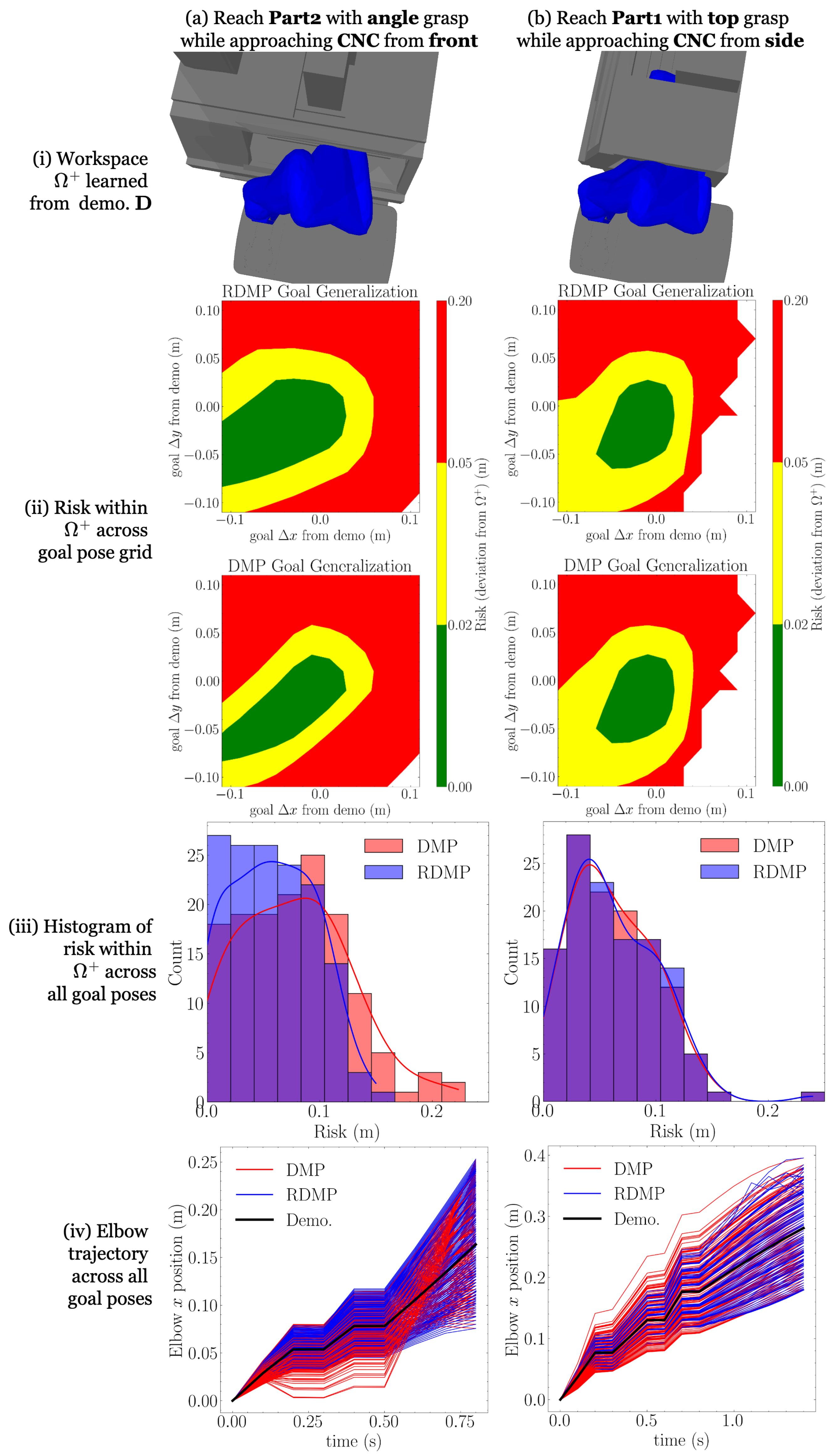
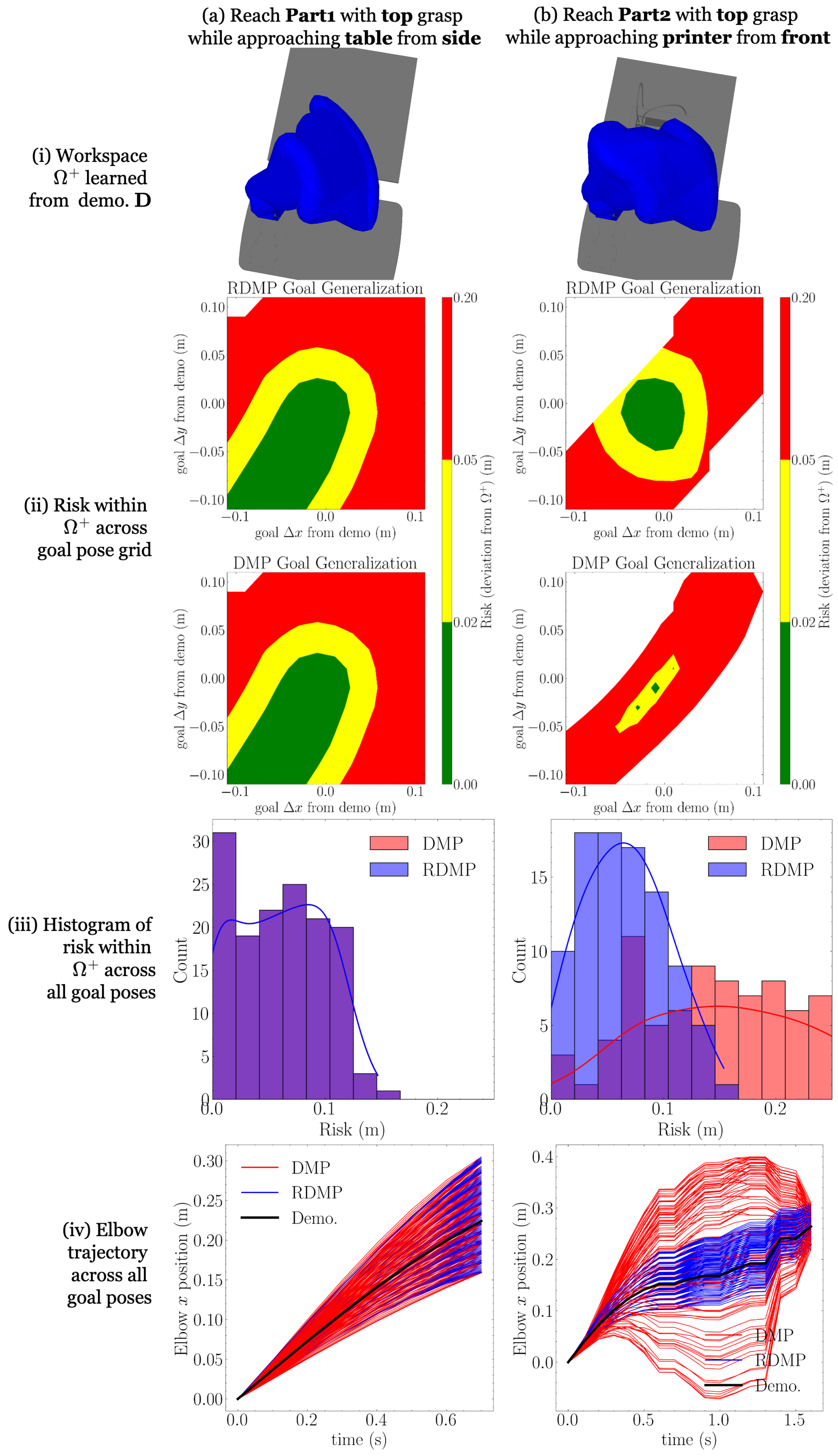
4.1. Workspace Learning from Demonstration
While demonstrations are commonly used to train skills capable of generalization, bounds on their generalizability are not commonly considered. In this section, we show how the same demonstration trajectories used for skill learning can be used to build sets capable of certifying the safety of new trajectories.
Consider a robot with
links, including end-effectors, mobile platforms, and other attachments. Each link’s volumetric geometries can be expressed as compact sets
∀
, where
is the set of compact subsets of
. The complete volume occupied by the robot at any configuration
q,
, can then be expressed by the union of all link geometries (we represent link geometries as meshes and use Trimesh [
49] for operations like mesh concatenation):
Meanwhile, suppose that a set of control points are sampled from the surface
of each link and collected in sets
. Then, the full set of control points at a configuration is given by the union of link control points:
To measure the distance between a point
and the boundary of a compact set
, a signed distance function (we use Pytorch Volumetric for SDF computation between meshes [
50]) is used, where
and
for surface points
. From this point-dependent SDF, we introduce a configuration-dependent SDF (C-SDF), similar to [
51]:
which finds the minimum clearance between the robot control points and the set
.
Now, consider a robot programmed to operate at a location
ℓ with static obstacle geometry
, resulting in a set of demonstration trajectories
which are
collision-free, meaning
Gathering all configurations across the trajectory set
yields the set of known safe configurations:
The safe configuration set is robot-specific, but we can consider the robot links at each configuration, which sweep through
to construct a generic safe Cartesian workspace:
With the safe workspace
, we can certify the safety of any trajectory
executed at location
ℓ without knowledge of
. First, since the demonstrations are collision-free, we know that
and
do not intersect:
. Then, we know that the obstacle set
must be a subset of the complement of
:
. Therefore, a sufficient condition for safety of a trajectory
at a location
ℓ is
In other words, if the robot trajectory does not enter the complement of the safe workspace, it cannot enter the obstacle set.
On its own, (
13) does not admit much flexibility in the design of new trajectories, as even the safe demonstrations
operate at the boundary of
. Instead, we leverage domain knowledge about the construction of the demonstrations to enlarge
. Guidelines regarding the minimum clearance between robot trajectories and workspace obstacles are common, specified by enterprise policies and industry standards, such as ISO 10218 2011-2 [
52] and ANSI/RIA R15.06 [
53]. Suppose that demonstrations used to construct
are known to have been generated using a standard, conservative minimum clearance of
, so
. Further suppose that a less conservative
represents the true acceptable clearance. Thus, a dilated safe workspace
can be formed:
where
is a ball of radius
centered at 0, and ⊕ is the Minkowski sum. A planar illustration of the safe workspace and its dilation is given in
Figure 1. Following a similar argument as above, we know that the obstacle set
is still a disjoint from the dilated safe workspace
:
. Thus, we have a sufficient condition similar to (
13) that is less restrictive:
Note that trajectories that do not satisfy (
15) are not necessarily unsafe; their safety is simply uncertain. A reasonable heuristic is to assume that the probability of obstacle collision increases the farther trajectories travel outside of the dilated safe workspace (or, equivalently, how far they travel inside its complement). Therefore, we define the
risk of a trajectory as
where
is a monotonically increasing function with
for
.
can represent either conservative risk functions, like
, or more relaxed ones, like
. In all experiments in this paper, we use
.
For notational convenience, we hereafter refer to the above procedure of mapping a demonstration trajectory set
at a location
ℓ to its dilated safe workspace as
4.2. Redundancy Dynamical Movement Primitives
Goals for manipulator tasks are most naturally expressed as end-effector goals . DMPs trained in task space allow the straightforward specification of goals in ; however, task space DMPs cannot encode the full motion of redundant robots, resulting in ambiguous joint space solutions. On the other hand, DMPs learned in joint space capture a demonstration’s full motion; however, joint space DMPs do not encode the whole-arm Cartesian behavior. Joint space DMPs also require inverse kinematics for goals to obtain joint space goals , which are ambiguous for redundant robots.
To learn the full motion of a redundant manipulator given new task space goals, the redundancy DMP (RDMP) is introduced. During training, a joint space demonstration trajectory is separated into task space and a compact null space representation , all of which are encoded as individual DMPs. Then, given a new task space goal , both task space and null space DMPs are simultaneously integrated to generate a new trajectory to reach g while preserving both task space and null space characteristics. The details of the compact null space representation are presented next.
4.2.1. Compact Null Space Representation
The manipulator Jacobian
maps instantaneous joint space velocities
at a particular configuration
q to the instantaneous task space twist
, composed of linear velocity
and angular velocity
. The forward and inverse velocity kinematics, respectively, are
where
is the Moore–Penrose pseudoinverse of
.
is the null space projection matrix, which projects any
into
, generating null space motion, meaning zero task space velocity, as
.
For a particular
,
represents the component of
contributing to null space motion, and can be computed by substituting (
18) into (
19) and rearranging:
Thus, (
18)–(
20) describe a one-to-one mapping between joint space velocity
and
. However, since
, null space motion describes motion along an
-dimensional manifold within
. As such, we can represent null space velocity more compactly in
dimensions. Let
be a matrix whose columns are the orthonormal bases of
, obtained from singular value decomposition (SVD). Then, any null space motion
can be expressed as
where
is a
compact null space velocity. Rearranging (
21) and substituting (
20), the compact null space velocity can be computed from
by
Therefore, at a configuration
q, a joint velocity
can be represented uniquely with
. The quantity
represents a redundant robot’s speed along its
null space manifold given its current configuration
q and joint velocity
. Note that RDMPs are not suitable for demonstrations that come close to kinematic singularities in
, where
as the null space computation becomes numerically unstable. However, since singularities pose other challenges, including loss of manipulability, manually generated robot programs are unlikely to contain them.
4.2.2. Training and Integrating RDMPs
In this section, we explain the RDMP implementations of
Train (4) and
Integrate (5). First, consider
TrainRDMP (Algorithm 1). Given a joint space demonstration
, corresponding task space Cartesian trajectories
and
are computed from forward kinematics and trained to weights
and
, respectively. Compact null space motion is computed using (
22) and integrated over time with
to form a demonstration
which is treated as a position DMP (
1) and trained to
. Additionally, the integrated
has no obvious physical meaning and thus new values cannot sensibly be chosen when the DMP is later integrated for reuse, so the original goal
is likewise recorded. Altogether, the RDMP weight vector is
| Algorithm 1 TrainRDMP |
- 1:
Compute forward kinematics over trajectory of duration sampled at : - 2:
- 3:
Compute null space trajectory: - 4:
for do - 5:
Compute null space matrix: - 6:
▹ note: - 7:
Apply Singular Value Decomposition to the null space matrix: - 8:
SVD - 9:
Form orthonormal bases from the first columns of : - 10:
- 11:
Compute null space velocity: - 12:
- 13:
Compute from integration of - 14:
Set null space goal as final trajectory value: - 15:
Train DMPs with (4): - 16:
Train - 17:
Train - 18:
Train - 19:
return
|
Then, given an initial configuration
and goal pose
, the task space and null space DMPs are simultaneously integrated to generate a new trajectory
, shown in
IntegrateRDMP (Algorithm 2). In
Section 4.3, RDMPs are compared to traditional DMPs in terms of generating lower-risk trajectories during generalization.
| Algorithm 2 IntegrateRDMP |
- 1:
- 2:
- 3:
- 4:
- 5:
Integrate task space and null space DMPs with (5) for duration and sampled at : - 6:
Integrate - 7:
Integrate - 8:
Integrate - 9:
Compute angular velocity and form task space velocity: - 10:
▹ lowers skew-sym. matrix to - 11:
- 12:
Compute compact null space velocity through numerical differentiation of - 13:
Compute joint space trajectory: - 14:
for do - 15:
Compute null space matrix: - 16:
▹ note: - 17:
Apply Singular Value Decomposition to the null space matrix: - 18:
SVD - 19:
Form orthonormal bases from the first columns of : - 20:
- 21:
Compute joint velocity and integrate joint configuration: - 22:
- 23:
- 24:
return
|


