Abstract
In this paper, we present a vision-based leader–follower strategy for formation control of multiple quadrotors. The leaders use a decoupled visual control scheme based on invariant features. The followers use a control scheme based only on bearing measurements, and a robust control is introduced to deal with perturbations generated by the unknown movement of the leaders. Using this formulation, we study a geometrical pattern formation that can use the distance between the leaders to scale the formation and cross constrained spaces, such as a window. A condition is defined for which a formation has rigidity properties considering the constrained field of view of the cameras, such that invariance to translation and scaling is achieved. This condition allows us to specify a desired formation where the followers do not need to share information between them. Results obtained in a dynamic simulator and real experiments show the effectiveness of the approach.
1. Introduction
In recent years, there has been significant research on formation control, focusing on distributed control approaches. Distributed control involves decentralizing decision-making processes among multiple agents, enabling them to make autonomous decisions based on local information and limited communication with neighbor agents [1]. We aim to contribute in the practical aspects of distributed control of multi-agent systems using onboard sensing. Thus, this work focuses on the formation control of multiple agents, where the feedback only uses visual information provided by conventional cameras. We propose a bearing-based formation strategy in which leaders and followers coordinate to achieve a geometric shape that can be adapted to the environment, for instance, to cross a window.
A bearing represents the angle or direction that a robot must move in a straight line to a target. Bearings can be computed from images of a target observed by a calibrated camera. There exist two main approaches for formation control using bearings [2]: bearing-based control requires knowing the relative position in addition to bearings, while a bearing-only control scheme only uses bearings’ information. Thus, we focus on the latter to avoid the use of the position estimation. Many bearing-based distributed control laws for multi-agent systems have been proposed in the literature. In [3], the relative angles of agents of a group of non-holonomic robots are used as bearings for formation control. In [4], a 2D bearing-only control law is described for navigation and tracking, which is inspired by the biological behavior of ants. In [5], the bearings are used as an indirect measurement of the relative position between each agent. A weak control law in the sense that each agent is free to choose its own heading within a range of values is proposed in [6]. Bearing measurements are used to maintain the initial heading to archive a given shape without collisions between agents.
Determining whether a particular geometric pattern of a network can be uniquely identified by bearings between its nodes is analyzed by rigidity theory [2]. A bearing’s rigid formation is invariant to translation and scale. Bearing-based control laws can be formulated using local or global frameworks. In [7], a gradient control law with a double integrator is presented, where the bearings are expressed with respect to a global reference frame. In [8], a global orientation estimation as a bearing input for the control law is proposed. The difference between the current and desired bearings is used in the control law. Furthermore, in [9], the consensus-based flocking control is combined with the bearing-based formation control. In [10], the tracking of multiple leaders is considered, enabling the capability of scaling and rotating the formation shape through the position of the leaders. In [11], a bearing-based control scheme is employed with a stationary leader that transmits information through a connectivity graph.
Bearing-only control laws are used for the purpose of trajectory tracking, as in [12]. In this approach, an integral term of the error is included to solve the tracking of leaders moving at a constant velocity; however, it does not deal with leaders with time-varying velocities. Other works, such as [13], propose a bearing-based formation control scheme that relies on local reference frames, while assuming constant velocity for two unmanned aerial vehicles (UAV) as leaders. Additionally, Ref. [14] extends bearing rigidity theory to address robotic systems with the Euler–Lagrange model, including non-holonomic robots. Recently, in [15], a velocity-estimator-based control scheme was proposed for formation tracking control with a leader–follower structure. Lastly, Ref. [16] describes the bearing-only formation control problem of a heterogeneous multi-vehicle system, where the interactions among vehicles are described by a particular directed and acylic graph and a velocity estimator is used.
There are some works in the literature about drones traversing a narrow passage, but to the authors’ knowledge, they are all for a single drone. The use of trajectory planning and state estimation techniques have been suggested in [17]. Some recent results in path planning might improve the performance of these kinds of approaches in terms of execution time and smoothness of the path and reduce collision risks [18]. In [19], a bioinspired perceptual design was introduced to allow quadrotors to fly through unknown gaps without an explicit 3D reconstruction of the scene. In [20], IMU measurements are used for orientation estimation and control. In particular, optical flow with respect to the closest window edge and the estimated normal direction to the window are used.
This work represents an effort to contribute to the practical aspects of distributed control of multi-agent systems using onboard sensing. We propose a leader–follower configuration together with a formation control strategy for quadrotors. The followers’ control uses only bearings extracted from monocular cameras. Different options of vision-based control laws are evaluated for leaders and followers, and the most appropriate combination is selected. We define a condition for which a formation has rigidity properties considering the constrained field of view of the cameras to achieve invariance to translation and scaling. In addition, we introduce a robust control approach for the followers, designed to effectively deal with time-varying perturbations resulting from the leader’s movements. The proposed approach is implemented both in a dynamic simulator and in real quadrotors, showing the effectiveness of the proposed control scheme.
The structure of the paper is organized as follows: In Section 2, we outline the preliminaries and formulate the problem. Section 3 details the proposed image-based formation control. Section 4 includes a series of simulations and experiments to validate the performance of the proposed control scheme. Lastly, Section 5 offers our conclusions and potential directions for future research.
2. Preliminaries and Problem Formulation
This section presents some background on the kinematic control of quadrotors, the basics on rigidity theory, and defines the problem addressed. To facilitate reading, a list of symbols is included at the end of the manuscript.
2.1. Motion Model
The kinds of drones considered in this work are quadrotors, which are a type of unmanned aerial vehicle (UAV) that offer numerous advantages due to their small size, high agility, and maneuverability. A quadrotor is a nonlinear and underactuated system; however, due to the property of differential flatness studied in [21], each state and input of the system can be written in terms of the so-called flat outputs. Then, in a quadrotor, the following four flat outputs can be controlled independently:
A classical scheme for a low-level velocity controller of a quadrotor is shown in Figure 1a. In this work, we assume that a low-level velocity controller can accurately execute the commanded control inputs, which are the linear velocities and yaw angular velocity . The outputs of the low-level controller are the torques for .

Figure 1.
Low-level quadrotor control and definition of reference frames. (a) Low-level quadrotor control. (b) Bebop 2 reference frames.
Then, we consider a simple motion model for the quadrotor as a decoupled single integrator for each coordinate as given in (2), where the vector of control inputs is the velocity vector ,
In our formation control scheme, we consider that each quadrotor has an on-board looking-forward camera. Thus, the camera reference frame, denoted by , and the drone reference frame, denoted by , are different, as shown in Figure 1b, and are related by a rigid transformation. We formulate vision-based controllers that provide camera velocities, which must be related to the quadrotor velocities. To do so, we use the following transformation denoted by , which is composed by a rotation and a translation ,
for our experimental platform Bebop 2, where is the skew-symmetric matrix operator.
As mentioned above, the four flat outputs are the controlled variables for the quadrotor and the four corresponding velocities (vector ) must be calculated from the visual servo control scheme giving , where and are the vectors of translational and rotational velocities, respectively, in the camera reference frame. Then, the following selection matrix must be introduced:
where is an identity matrix of size 3, and the transformation is applied as follows to compute the velocity commands of the quadrotor:
According to (4), the vector of camera velocities is computed from visual image calculations as detailed in Section 3. This vector is transformed using to the quadrotor reference frame. From the resulting vector with six components, the four velocities associated to the flat outputs are selected through the matrix and given to the quadrotor as reference velocities () to be executed by the low-level controller (see Figure 1a).
2.2. Bearing Rigidity Theory
We address the formation control using a bearing-only-based approach. We use cameras as the main sensor to obtain bearing measurements. The bearing rigidity theory investigates the conditions under which a geometric pattern of a network is uniquely determined [2]. A bearing between two drones i and j is defined as
where for are the positions of the drones. The vector can be estimated from visual information as depicted in Figure 2, where ArUco markers are mounted on the drones and its central point is projected to a unitary sphere and expressed as a unitary vector.
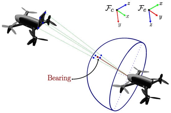
Figure 2.
Estimation of bearing measurements using ArUco markers whose central point is represented as a ray beam within the unitary sphere.
The survey in [2] provides comprehensive information on the theory of bearing rigidity. The following definitions are important for the remainder of the work.
Definition 1.
A network of n nodes in with and is a tuple , where is a graph with vertex set and edge set , and is the vector of stacked positions of the nodes , with . if node i receives information from node j.
Definition 2.
The set of neighbors of a node i, denoted by , consists of all the nodes such that .
Definition 3.
For any non-zero vector , we define an orthogonal projection matrix as
Definition 4.
Given a network with no collocated nodes, we define the bearing Laplacian as
where is the th block of the submatrix of , and is the bearing from node i to node j.
In this definition, “no collocated nodes” means that every node in the network occupies a distinct and non-overlapping spatial location.
Definition 5.
Given two networks () and () with the same bearing Laplacian matrix, the network () is infinitesimally bearing rigid if corresponds to translational and scaling motions .
This definition means that an infinitesimally bearing rigid formation can be uniquely determined up to a translation and a scaling.
Definition 6.
For an infinitesimally bearing rigid framework, the following properties hold:
- , i.e., the eigenvalues of accomplish ,
- .
This definition states that a framework is infinitesimally rigid in if and only if , and in if and only if .
Definition 7
(Problem formulation). For a group of n quadrotors where two of them are considered leaders and the rest followers, formulate a vision-based control scheme using only visual feedback. The leaders must reach desired poses specified by reference images, and the followers must track them in formation using only bearings. For followers, the condition of infinitesimal rigidity must be guaranteed and, by taking advantage of its invariance to translation and scaling, we should apply the control scheme to pass the formation through a narrow space, for instance a window.
3. Proposed Image-Based Formation Control
We adopt the control flow chart of Figure 3, which describes a generic visual servo control approach for quadrotors. The depicted control scheme involves the use of the transformation function that depends on the type of agent: the leader control is based on invariant features, and followers’ control is based on bearings. Both control laws can be considered as image-based visual servo control (IBVS) since only 2D information from images is used.
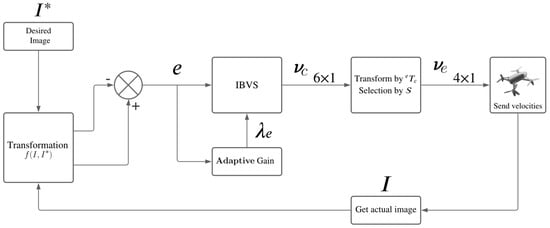
Figure 3.
Generic image−based visual servoing scheme for quadrotors, where the visual information is transformed through to obtain invariant features or bearings.
We propose to use adaptive gains for improving adaptability and accuracy [22]. The form of the adaptive gains used is as follows:
where represents the gain when the error is zero, which determines the sensitivity of the controller to small deviations, is the gain when the error tends towards infinity, providing capacity to correct large errors, and determines the slope of at , controlling the rate at which the controller gain adjusts as the error magnitude increases.
3.1. Leaders’ Control Based on Invariant Features
In this section, we specify the transformation for the two leaders’ control, with the goal of driving them independently to desired poses. Invariant features refer to visual information within an image that remains unchanged under a particular motion, for instance translation or rotation. These features allow the design of decoupled visual control laws, where translation and rotation can be controlled separately [23].
3.1.1. Invariant Features for Translation Control
Consider that a minimum of four non-cyclic, non-collinear, but coplanar feature points, denoted as for , can be detected in the observed scene. They are projected onto the unitary sphere, as depicted in Figure 4a. The distances between the feature points in Euclidean space on the sphere are invariant features; since a camera rotation preserves Cartesian distances, it is straightforward that the feature for is invariant to camera rotation motions (see Figure 4b). We can define this distance by

Figure 4.
Invariant image features for IBVS, drone rotation, and invariant distance. (a) Invariant image features for IBVS. (b) Drone’s rotation and invariant distance.
Then, an invariant feature can be defined as one of the following options:
The first option in (9) was proposed in [24] and (10) was proposed in [17]. We compare the performance of the controller from these invariant features to control the translational motion of the leaders through the velocity vector . In this case, the transformation referred to in Figure 3 represents the computations to obtain k invariant features to define the vector:
3.1.2. Using Distance between Points on the Sphere
The time derivative of the invariant feature as defined in (9) is obtained as follows:
The dynamics of the point on the sphere according to [25] is described as follows as a function of the camera velocities and :
where is the orthogonal projector given in (6), and is the skew matrix of a vector .
Let us define the factor ; substituting the dynamics of (12) into (11), we obtain
where is the interaction matrix for one invariant feature . Notice that the terms associated with the rotational velocity cancel each other, and the change in the image feature only depends on the translational motion.
3.1.3. Using the Inverse of the Distance between Points on the Sphere
Now, if we take as the inverse of the distance between the projection points and on the sphere given by (10), the time derivative results in the same expression (13) just with a different scaling , and the rotational velocity does not have any effect either.
In any case, one image feature is not sufficient to compute the velocity vector ; several Equation (13) must be stacked to compute a pseudoinverse . To do so, at least four points must be taken on the sphere that are neither collinear nor concyclic, but coplanar, leading to six invariant feature distances. Since we do not have access to the 3D points, the terms , for , must be estimated as a single constant value. Thus, the translation control input is given by
where , , with , and is defined as a constant or an adaptive gain, as described in (8).
3.1.4. Rotation Control Law
Thanks to the decoupling introduced by invariant features, the translational and rotational motions are independent, and they can be controlled using a different controller. For example, classical image-based visual servoing [26] can be used for rotation control. To do so, at least three non-collinear points are needed for the interaction matrix to be pseudo-inverted.
Let be a point in the normalized image plane taken from a vector of the k features. Its dynamics, described in [26], is given by:
where is the angular velocity input in terms of roll, pitch, and yaw.
Similarly to the approach of translational motion, we can stack the interaction matrix for at least three non-collinear points to build the required pseudo-inversion. Then, the vector of angular velocity is given by:
where , , with k the number of point features in the image, and is defined as a constant or an adaptive gain as described in (8).
3.2. Followers’ Control Based on Bearings
The control law for followers is based on bearings, so that the corresponding function of the control flow chart in Figure 3 is used after some image processing calculations, as shown in Figure 2, to obtain k bearing measurement data points to define the vector
where each bearing is of the form (5), . There exist two options to define bearing-only-based control laws, which are described in the next subsections.
3.2.1. Control Based on Orthogonal Projection
The approach presented in [27] serves as the basis for our control law for followers, where in this case, the bearings are measured using the local frameworks. This approach makes use of the orthogonal projection operator defined in (6). The following control law addresses the translational and rotational motion required to obtain a formation around leader agents:
Here, the current and desired bearings from agent i to agent j are represented by and , respectively, both in . is the orthogonal projection of a vector given by (6). Furthermore, and can be constant or adaptive gains, as in (8). The matrix , for , indicates the transformation from the body frame of agent k to the global frame. As a result, the matrix describes the relative rotation from the agent framework i’ to the agent framework j’. When the bearings are measured with respect to a common reference frame for all the agents, such that for , i.e., all frameworks are already aligned, the control law is simplified to the following translational controller:
3.2.2. Control Based on Difference of Bearings
The following approach for bearing-only formation control was proposed in [28]; for an agent i, the translational velocity vector is given by:
where are the current and desired bearings from agent i to agent j, respectively, both expressed with respect to a common reference frame.
This approach is a gradient descent control law that can be modified by rotating the desired bearings to align with the local framework, similar to the orthogonal projection control scheme. This generalization presents an alternative method for choosing the control law for the follower agents and can be expressed as follows:
where are constant parameters or adaptive control gains given by (8).
Figure 5 illustrates a scenario with three agents, denoted and , taking exactly the same positions. Assuming that the first agent can measure the bearings, there are two desired bearings designated as and . We analyze the use of the control laws (16) and (19) to derive the velocity input, providing information on the necessary motions to achieve the desired positions. In particular, these control laws produce distinct magnitudes and directions for the velocity control while simultaneously minimizing the error between the current and desired bearings. Despite the differences, each control law ensures that the current bearings asymptotically converge to the desired bearings, thus enabling the desired formation to be achieved.
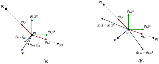
Figure 5.
Geometric visualization of bearing-only control laws: the agents are depicted as black points, with the current bearings represented by red arrows, the desired bearings by green arrows, and the resulting velocity with their corresponding control law by a blue arrow. (a) Orthogonal projection control law (17). (b) Difference in bearings’ control law (18).
The relative rotation, denoted as in (16) and (19), corresponds to the transformation that aligns a desired bearing from the desired local frame to the current local frame. We introduced this transformation in (19) since the difference in bearings has only been used in the literature considering measurements in a global reference frame. Furthermore, notice that in the described control laws, the resulting velocity vector is expressed in the camera’s framework, and for implementation purposes on the quadrotors, it has to be transformed by using (4) to obtain .
3.2.3. Robust Control for Followers
The control laws of the previous sections are sufficient for the follower agents to reach a formation but are limited to static leaders. This means that when the leaders are not stationary, which is our case due to the visual servo control that generates the velocities given by (14) and (15), the convergence of the bearing error is not guaranteed. This issue has been addressed in the literature by including an integral term in the controller to reject the perturbation induced by the leaders’ motion; however, this is solved for leaders with constant velocities [12,15,29,30]. Since our objective is to maintain a bearing-only control scheme without the need for estimating the leaders’ velocity, we treat the leaders’ velocity as an unknown time-varying perturbation that must be rejected.
Without loss of generality, let us consider the case of bearing-only control based on orthogonal projection without rotations (17). The convergence of the bearings’ error to zero, and therefore, the convergence of the agents’ position to the desired formation, must be ensured despite the perturbation being induced by the leaders’ motion. The effect of the leaders’ motion can be modeled as a modified measurement of the current bearing affected by a perturbation . Then, the bearings’ error in (17) considering this perturbation can be written as:
where the term is assumed to be bounded and yields an undesired velocity component.
We propose to introduce a robust control technique in the control law of the followers, in particular the Super-Twisting Sliding-Mode Control (STSMC). This is a nonlinear control technique used to control systems that have uncertainties and disturbances [31]. It extends the conventional Sliding-Mode Control method in order to generate continuous control signals.
The basic idea behind the STSMC is to guide the system’s state variables along a specified sliding surface, and once there, the system is slid over that surface towards the equilibrium point. In our case, the equilibrium point corresponds to null bearing errors, and since we have first-order dynamics for each coordinate, the sliding surface () is directly defined as the measured bearing errors:
Thus, we introduce the bearing errors in the formulation of the STSMC to yield the velocity vector that governs the translation of the follower agents as follows:
where the parameters are proportional and integral control gains to be tuned. These gains can also be adaptive gains, as described at the beginning of the section. The stability of the STSMC has been studied by using the Lyapunov theory in [32], which guarantees finite-time convergence to the sliding surface in spite of bounded perturbations for an adequate tuning of control gains. Constraining each agent to reach and maintain its position on the sliding surface corresponds to achieve null bearing errors; therefore, the current bearings reach their desired values and the specified formation is achieved in spite of the perturbation due to the time-varying motion of the leaders.
3.2.4. Scalability of the Bearing-Only Based Formation Using Vision
The notions discussed in Section 2.2 and the controllers of the previous section, allow different leader–follower configurations. To ensure that a formation control remains invariant to translation and scaling requires a careful selection of a geometric shape that obeys the conditions of an infinitesimal bearing rigidity (IBR) network. The IBR property of a network requires maintaining a minimum of edges [2].
In the section on implementation results, we analyze a case study with 3 agents and the conditions of a basic configuration to guarantee IBR. Here, the scalability of a fleet of agents is analyzed considering the addition of more agents, as shown in Figure 6. As mentioned above, when adding a new agent to the fleet, the network must have at least edges. Thus, if we assume that the network with n agents already had IBR, then
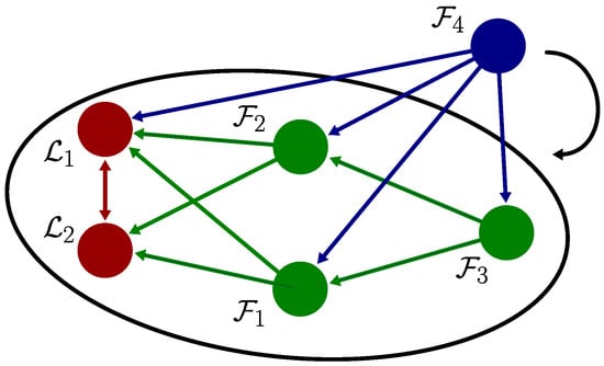
Figure 6.
For an IBR network (encircled with two leaders and three followers ), adding a new agent requires setting up bearing links with at least two agents to maintain the IBR condition. In this case, the new agent can join the fleet by following, for instance, any two (, ), three (, , ), or four agents (, , , ).
Thus, the key factor is to ensure that every new agent maintains visibility and bearings can be computed from at least two others, increasing connectivity and maintaining rigidity in the formation despite the limited field of view of the camera. We take this scalability condition to define an adequate bearing-only based formation for drones, each one with a looking-forward camera with limited field of view.
Notice that the previous condition allows each quadrotor to perform tasks independently of the others, without the need for sharing data, relying solely on its own local observations of two other agents. We consider that the leaders operate autonomously and independently from each other, without any synchronization, although it is an aspect to take into account for future work.
4. Implementation Results
This section presents the results of the implementation of the proposed approach in both simulations and experiments with real quadrotors.
4.1. Comparison Studies
In this section, we present comparisons of the different options of control laws described in the previous sections both for leaders and followers in order to achieve the best performance of the overall control scheme. These comparisons were conducted by using a Python implementation of the approach.
4.1.1. Leaders’ Control
We present an initial evaluation in Python of the control laws using invariant features for the leader agents. The control law (14) was evaluated by considering a free-flying camera with six degrees of freedom and the perspective projection of four coplanar points that led to six invariant features.
The control law included both the translational controller (14) and the rotational controller (15). The results are shown in Figure 7 for both the distance between points and the inverse of the distance for the same initial condition and control gains. Both control laws exhibited good performance in both the image space and the 3D space. However, it can be seen that the control law (14) using the inverse of distances generated a very direct trajectory towards the goal with lower values on the magnitude of velocities.
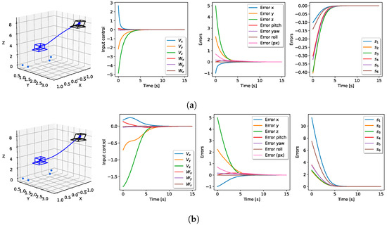
Figure 7.
Performance of the invariant control laws including rotation control; the initial pose was rotated in yaw by 10 degrees. The 3D pose, velocity input, pose, and distance errors are shown. The blue camera frame represents the final pose, and the black one shows the starting pose. Both simulations used the same starting poses and fixed gains (, ). (a) Performance of the control law (14) with using distances. (b) Performance of the control law (14) with using the inverse of distances.
In order to have a clear result on the performance comparison of both invariant features, 100 simulations were run for a single camera from different initial poses to the same final pose. Figure 8 shows the camera starting from random poses while maintaining sight of the 3D points highlighted in royal blue. The pose was modeled as a multivariate uniform random variable considering only the four degrees of freedom controlled in a quadrotor as . For all cases, the desired pose was specified as . It is known that the optimal trajectory in the 3D space is a straight line to the target position; then, from each random initial position both control laws were executed and compared to that line, using the root-mean-square error for determining the closest trajectory to the optimal one. As a result, of 100 simulations were closed to the straight-line trajectory using the inverse of the distance, while 2% were more straight trajectories using the distance. Therefore, the best option was to use the inverse of distances as the translational control law for our leaders, coupled with the rotational control law of (15).
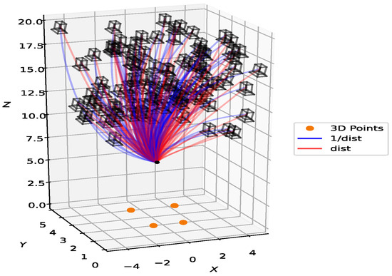
Figure 8.
Comparison of a flying-free camera trajectory using two control laws in a 3D simulation, highlighting the superior performance of the inverse-distance control (98%) over distance-based control (2%). The black frames represent initial positions, the red lines represent trajectories using control law (14) with , the blue lines represent trajectories using control law (14) with , and the red dot represents the desired and final positions for all simulations.
4.1.2. Followers’ Control
This section presents the behavior of the bearing-only control laws through Python simulations. We simulated a scenario where two sets of four static 3D points were projected onto a single free-flying camera. We considered only one agent which used sufficient bearings in order to achieve a desired position, that is, a visual servoing task was solved using the feedback of bearings.
Infinitesimal Bearing Rigidity Condition
Before we present the simulation results, we analyzed the rigidity condition for the described scenario. Each set of four points simulated the detection of a rectangular marker mounted on a leader agent, and the bearings were measured as in Figure 2. To guarantee infinitesimal bearing rigidity (IBR) as in Definition 6, n agents need at least edges (bearings among agents) [2]. In this simulation, (two static leader agents represented by the markers and the camera agent), then a minimum of three bearings were needed. To accomplish this condition, we assumed the existence of an edge of the connectivity graph between the leader agents represented by the static markers, and the other two bearings were obtained from the moving camera to each leader.
Now, we provide an evaluation of the IBR property within the geometric pattern obtained from the desired configuration. The bearing Laplacian was built as defined in (7). The graph was for the network configuration denoted as , with the positions proposed as . Thus, the bearing Laplacian, was the following matrix:
Notice that the rank of matrix is five, and the condition of IBR holds since with and (dimension of the agents’ position).
Comparison between Bearing-Only-Based Controllers
Figure 9 illustrates the scenario described in the previous section and compares both the bearing-only control laws given in (16) and (19). For this scenario, the desired pose was designated as and the initial pose as , referring to the x axis, the y axis, the z axis, and the rotation of the yaw.
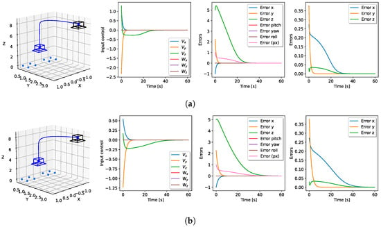
Figure 9.
Performance comparison of bearing-only-based control laws. The visualization includes 3D pose, velocity input, pose error, and bearing errors. The final pose is marked by the blue frame, and the initial pose is indicated by the black frame. The simulations maintained consistent initial poses and utilized fixed linear and angular control gains with and . (a) Performance of the control law (16) based on orthogonal projection. (b) Performance of the control law (19) based on the difference in bearings.
It can be seen that the velocities produced by the control law in (16) were significantly higher than those generated by the control law of (19) although the magnitudes of the initial feedback errors in both cases were the same. Therefore, the convergence time was shorter using the orthogonal projection than the difference in bearings, and we considered that controller as the best option to experiment with real quadrotors. Notice that the slowest convergence was on the z-axis position in both simulations. This might be due to the camera’s optical axis being in that direction, resulting in small changes in this coordinate of the bearing measurements and consequently, a small error in that coordinate. The stability of both control laws for stationary targets was demonstrated by a Lyapunov analysis in [33] and [12], respectively.
Robust Bearing-Only-Based Control
Figure 10 presents the results of using the proportional control law of the orthogonal projection in (16) and the robust control law of (21) in a scenario in which the 3D points generating the bearings, denoted by for , were not static. As mentioned above, followers lacked access to the velocity information of the leaders or their movement. A time-varying velocity was introduced into the 3D points, represented by . In both simulations, the initial position was set at , while the desired position was with a null rotation in both cases.
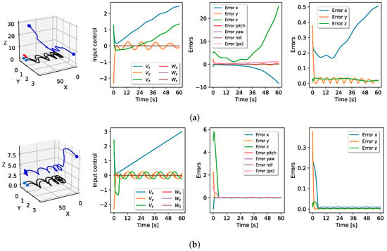
Figure 10.
Performance of a bearing-only control law with simulated moving leader agents. The 3D pose, velocity input, pose errors, and bearing errors are shown, respectively. The initial configuration is depicted as black cameras and black dots, the trajectory and current position are shown in blue, and the desired configuration is represented by the red camera and royal blue dots. The control gains were set as and for both implementations and for the STSMC. (a) Performance of the control law given by (16), i.e., without STSMC. (b) Performance of the control law given by (21), i.e., with STSMC.
Figure 10a illustrates the control inputs given by the proportional control law (16). An increasing pose error can be seen on the x and z axes, and there was no convergence of the feedback errors. In contrast, convergence was achieved using the robust STSMC; errors of about in the feedback error and in the norm of pose error were obtained. In Figure 10b, there can be seen an increasing velocity in the x-axis, which was expected due to the constant motion of the leaders in that direction. Nevertheless, it should be pointed out that the velocities with STSMC generated a small chattering effect due to the oscillations produced by the period of sine and cosine functions in the movement of the 3D points.
4.2. Experiments in a Dynamic Simulator
The leaders play an important role in the proposed scheme, since they are able to modify the scale of the formation; they might drive the whole fleet through narrow spaces like a window. In this section, we present an experiment using the Gazebo dynamic simulator. The simulation was created using the Noetic Ninjemys version of the Robot Operating System (ROS), Gazebo 11 with the C++ programming language, and the RotorS package running on Ubuntu 20.04. The simulated drones used for this work were based on an implementation of the repository at https://github.com/simonernst/iROS_drone.git (accessed on 24 July 2024), which was adapted to model Parrot Bebop 2 drones, taking into account their real physical characteristics and including a camera and an ArUco marker on the rear of the quadrotor. The size of the images used was pixels, and the camera calibration matrix was set as
The complete implementation of the Gazebo simulation, along with explanations and the installation process, is available at https://github.com/deiividramirez/bearings (accessed on 24 July 2024).
4.2.1. Simulation Setup
The experiment consisted of bearing-based formation control to address the task of passing a group of drones through a window to enter a room. Initially, the drones were outside the room, where they had to obtain a formation. Then, they had to move in formation towards the window while scaling the formation size to be able to cross the window and get into the room. In that scenario, we considered that two drones were leaders and formulated their control by using two different desired target images to define target positions. The first goal location was just before reaching the window, while the other was in the center of the room, which allowed the formation to cross the window. In the first control stage, corners of the ArUco markers were used as image features and in the second stage, ORB image features with a Flann matcher and a KLT tracker were used. Due to the position in which the target images were captured, it was assumed that the quadrotors maintained a safe distance from the walls and each other during the motion.
The primary function of the followers was to maintain their relative position to the leaders using a bearing-only formation control scheme. We assumed that the connectivity of the network was sufficient to be IBR taking into account the condition illustrated in Figure 6. Therefore, the configuration of the followers was such that they could have in their frontal view at least two other drones. Moreover, we assumed the existence of a fixed bearing between the two leaders (approximately fixed in practice). Identifying each drone was needed, which was achieved by using a unique ID in the form of an ArUco tag attached to its back.
Unlike leaders who used two target images along their path, each follower used a single target image to obtain the desired bearings. This simplified the guidance process as followers focused on aligning with that visual reference by minimizing bearing errors. Nevertheless, they might have had more target images if the geometric pattern of the formation had to be changed. In our case, the formation was kept during the motion and was only scaled.
Although initial positions can be set arbitrarily, it is important to ensure that the ArUco markers remain within the field of view of each drone’s camera. This requirement is essential for accurate perception and navigation, allowing the drones to efficiently search for their respective targets. We set the initial and desired positions as depicted in Figure 11, with the poses given by in meters and radians, respectively. The values of the initial positions are shown in Table 1.

Figure 11.
Environment simulated in Gazebo; there are two leaders, and , represented by red drones, and two followers, and , depicted in white. (a) Initial drone positions. (b) Desired drone positions.

Table 1.
Initial and desired positions within the Gazebo world for the fleet, consisting of , , , and .
Notice that due to the change in target image, an undesired acceleration in the motion of the leaders appeared. We addressed this issue by introducing a smoothness function , defined in (24) as an additional gain to the control laws for allowing a seamless transition. This transition could be used at multiple time intervals. Hence, if we denote an interval for , then the intended transition occurred from to seconds, where , as shown in the example of Figure 12.
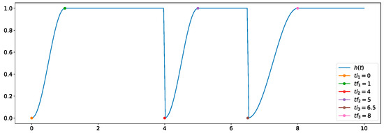
Figure 12.
Example of a smooth transition using the time intervals , , and , employing the function in (24).
Henceforth, the control input for the leaders was adjusted using this smooth transition, which included two distinct time intervals. The initial interval guaranteed a smooth start-up of the control, while the second interval took into account the change in the desired image, avoiding any abrupt discontinuity. The transition was applied as follows:
where is a velocity vector denoted generically as given by any of the proposed IBVS control laws. In this case, the transformation (4) was applied to instead of .
4.2.2. Simulation Results
Figure 13 shows the trajectories in the 3D space resulting from the simulation of the control laws for both leaders and followers. The leaders were initially aligned on the longitudinal axis, with a large lateral separation, which was reduced to scale the formation that fit the size of the window as specified by the desired pose, around m behind the window. Upon moving towards the second desired pose on the other side of the window, around 2 m, the whole formation crossed the window, maintaining the desired bearings. Adaptive gains given by (8) were used to achieve good performance for the STSMC control, with the parameters detailed in Table 2.

Figure 13.
Three−dimensional paths followed by the quadrotors in the Gazebo simulation. Leaders and correspond to drones 1 and 2, while followers and correspond to drones 3 and 4.

Table 2.
Parameters of the adaptive gains for control laws in the Gazebo simulation.
Figure 14 presents some snapshots of an external view of the formation. At 0 s, the drones started from their initial positions. At s, the follower’s bearing error was significantly reduced, indicating that the formation was almost complete. At s, the formation was successfully established. At s, a change in the desired image triggered a smooth transition, affecting the velocities sent to the leaders. At 25 s, the drones were about to enter the room. Finally, at s, all drones had reached their desired positions, as determined by the desired images. For a detailed view of this simulation, see the video demonstration at https://youtu.be/FIPAQ5luHYw (accessed on 24 July 2024).
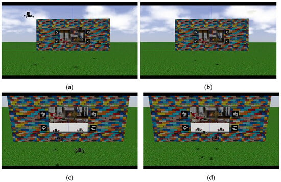

Figure 14.
A series of snapshots showing different instants in the video of the Gazebo simulation, available at https://youtu.be/FIPAQ5luHYw (accessed on 24 July 2024). The video is approximately s long. (a) At 0 s. (b) At s. (c) At s. (d) At s. (e) At 25 s. (f) At s.
Figure 15 shows the evolution in time of important variables in the Gazebo simulation. Recall that the STSMC methodology was implemented solely for followers and proved to be highly effective in helping them reach their desired positions in the formation.
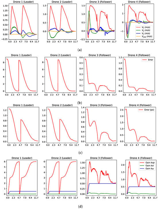
Figure 15.
Plots of important variables in the Gazebo simulation. (a) Velocity inputs from control law for leaders (14) with and followers (16). (b) Feedback error for the control law. (c) Normalized pixel error computed as the average error between matched points in the current and target images. (d) Adaptive gains for every drone.
Figure 15a illustrates the velocity inputs for the drones, where each velocity command was transmitted every 30–45 Hz. The maximum velocity sent reached approximately 1.93 m/s and did not cause saturation during this simulation. The execution of the two stages of the strategy was clearly seen. The first was during the first 4.8 s, the time during which the leaders reached the desired position in front of the window. After that, the leaders’ velocities increased due to the change in the target image, which occurred when the normalized pixel error first dropped below the pixel threshold. Then, the transition given by (24) was triggered, and the change in velocities was smooth. The second stage of the control strategy moved the leaders forward to cross the window using the point features detected in the scene inside the room. Notice that the leaders had a small sudden change at about s. This was due to a rematching of the image points every 3 s as long as the feedback error was less than . This reset was necessary to manage the accumulated pixel error of the KLT algorithm used to track these points. Consequently, the new ORB points generated a slightly different error at that instant.
The expected behavior for both stages of the control strategy could also be observed in the velocities of the followers. It could be seen in the velocities of the followers around 7 s, when the same velocity input was sent for approximately one second; this was attributed to the camera’s lack of detection of the ArUco marker in the currently image capture. Several factors could cause this issue, such as partial occlusions that prevent marker recognition, transmission errors, or even image quality issues. Hence, if the target marker is not detected in the current frame, the previous velocity command should be sent.
Both the feedback error and the normalized pixel error are depicted in Figure 15b and Figure 15c, respectively, and demonstrate the expected behavior. At the start, the error decreased as the leaders guided the followers towards the window. However, as drones crossed the window, an increase in error was observed until both leaders slowed down to reach their target positions inside the room. The use of adaptive gains in the system was highly advantageous for both leaders and followers, as depicted in Figure 15d.
4.3. Experiments with Real Quadrotors
Unfortunately, we only had two quadrotors for our experiments with real drones. Due to that limitation, we split a similar experiment to the one developed in the Gazebo simulation into two parts. The first part was to show the two drones acting as leaders, using the control law based on the inverse of distances (14). In the second part, we used the same two drones acting as followers, using the orthogonal projection control law (16). The experiments were developed in Python 3 on Ubuntu 20.04, using the PyParrot library available at the repository https://github.com/amymcgovern/pyparrot (accessed on 24 July 2024). This library was adapted mainly in two aspects: the frequency to send control commands was fixed to 30 Hz since the library originally implemented an adaptive control cycle, and the ffmpeg API to manage image processing was replaced by an OpenCV implementation to allow an adequate processing at that video frequency. The size of the images used was pixels, and the following matrix of intrinsic parameters was obtained through a calibration procedure:
In this experiment, due to the lack of texture in the walls of our laboratory, we placed a total of eight ArUco markers, four placed before entering the narrow passage and four placed after crossing the narrow section. This placement allowed for an appropriate setup for fast feature detection.
4.4. Visual Control of the Leaders
Figure 16 shows the desired images of the leaders. The narrow space emulating a window is delimited by the two white columns with ArUco markers, as depicted in the subfigures at the top. Navigating through this space and fitting within its width was a requirement for the two leaders. This experimental scene is just an example to emulate a narrow passage; the columns were set in an arbitrary orientation and the quadrotors were initiated in arbitrary poses in order to show the effectiveness of the approach for general conditions.
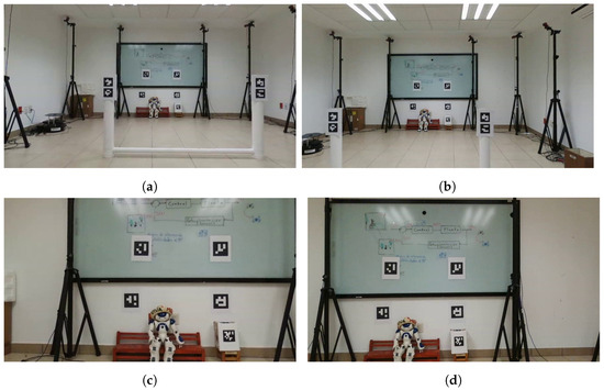
The initial configuration included a non-zero yaw angle that had to be corrected. Figure 17 show snapshots of this experiment. At 0 s, the drones were in their initial positions in the designated space. At seconds, they took off and initiated the control law. At s, the leaders were approaching their first desired positions. Then, at s, the smooth transition, as defined by (24), was initiated by a shift to the second desired image. At s, the drones moved towards their new desired positions. Finally, at s, they arrived and experienced slight oscillations caused by their own wind perturbations. A video of this experiment with a duration of s is available at the following link: https://youtu.be/eyNs8avFves (accessed on 24 July 2024).
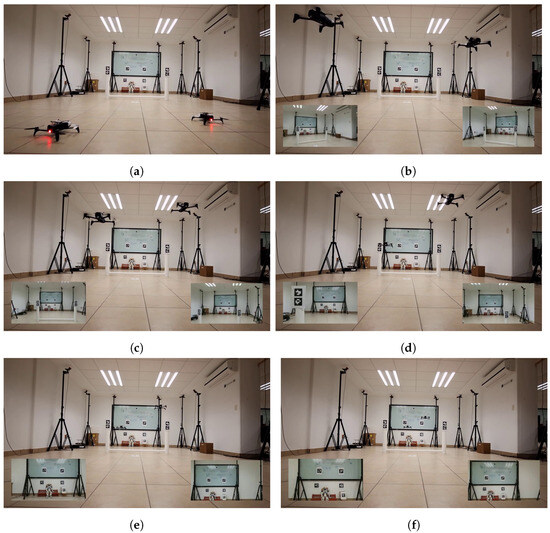
Figure 17.
Snapshots taken from the video of the experiment for the leaders at different times https://youtu.be/eyNs8avFves (accessed on 24 July 2024). The video lasts about s. (a) At 0 s. (b) At s. (c) At s. (d) At s. (e) At s. (f) At s.
The results of this experiment are presented in detail in the plots in Figure 18, showing the velocities and resulting errors of the experiment. We restricted the maximum velocity to approximately m/s in both situations to ensure that the drones operated safely within the enclosed space. Figure 18a shows the velocity profiles of the drones. The saturation in the x-axis velocities can be observed, indicating that the drones required significant corrections along this axis compared to the other two axes.
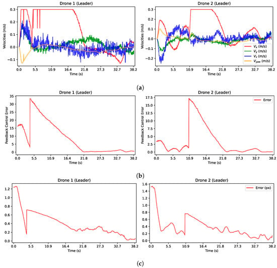
Figure 18.
Plots of important variables for the experiment with the two Bebop 2 quadrotors as leaders. (a) Input velocities from control law for leaders (14) with . (b) Feedback error for the control law. (c) Normalized pixel error computed as the average error between matched points in the current and target images.
The drones maintained a distance of about m from each other about their desired positions in both experiments. However, it was clear that the curves of the y- and z-axes exhibited more change, primarily due to the inherent mutual perturbations caused by the propellers, resulting in small oscillations. The velocity curves of the first leader, , exhibited some discontinuities, for instance at 1, , and s in Figure 18a, which can be attributed to perturbations between both drones. Turbulence temporarily destabilized the first leader, causing abrupt movements and a lack of detection of the ArUco marker. In contrast, such deviations were not evident in the motion of the second leader .
The feedback errors computed from the invariant features are shown in Figure 18b and followed an expected decrease pattern reaching a minimum around s; after that, a discontinuity appeared due to the shift in desired images, which was mitigated in the velocities by using a smooth transition. Afterward, there was another expected decrease in error. As the error approached to zero, perturbations between the drones became evident, resulting in oscillations as the drones approached their final desired positions. A similar pattern is observed in the normalized pixel errors shown in Figure 18c. However, the oscillations in these figures are more pronounced because of the magnitude of the error.
4.5. Bearing-Based Control of the Followers
The goal of this experiment was to show the dynamic scalability of the geometric pattern within the bearing-based formation control as leaders agents moved. Given that only two drones were available for the experiment, we emulated the behavior of the leaders by using two teleoperated Differential Drive Robots (DDRs). Due to the nonholonomic motion constraint of the DDRs and to keep the ArUco markers aligned with the followers, they were teleoperated to move in straight line for approximately 2 m in a particular orientation as depicted in Figure 19. This action effectively reduced the distance between the two leaders. Each DDR was equipped with ArUco markers to compute bearings.
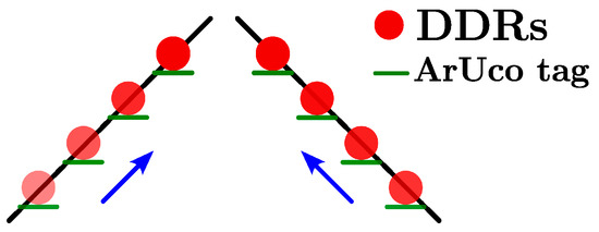
Figure 19.
Illustration of the paths followed by the DDRs acting as leaders, ensuring alignment of their ArUco markers to be detected by the Bebop 2 followers.
Figure 20 displays the target images for this experiment. Unlike the leaders, only one desired image was needed to obtain the bearings. Once the desired bearings were obtained, the control law could be executed. The goal here was to dynamically adjust the scale of the geometric pattern, moving from a larger to a smaller configuration.

Figure 20.
Hovering initial position and desired images for the Bebop 2 followers, used in their control law using the orthogonal projection (16). (a) Desired image for follower . (b) Desired image for follower .
As previously mentioned, the STSMC was triggered from the beginning, whereas the feedback error was greater than . This decision was important to maintain precise formation control without overshooting of the followers’ error in the last part of the experiment. This may cause velocity discontinuities, but it is important to mention that drones are capable of handling these velocity changes if they are of low magnitude.
We took snapshots at various time intervals during the video of 79 s in this first experiment, a visual representation of which is shown in Figure 21. To observe the entire experiment, visit the link https://youtu.be/xyGV7B5biZU (accessed on 24 July 2024). The initial positions of the drones in the room and in hover mode were observed at 0 and s, respectively. Around s, the followers were approaching their desired positions with the largest separation, then the Turtlebots started moving to reduce the distance between them, allowing for scalability in the formation. At s, the followers had reacted to the leaders’ movement and were actively adjusting their positions, managing the propeller perturbations while keeping the bearings and ArUco markers within the camera’s field of view. At s, the followers were about to reach their final positions, and at s, they had successfully arrived at their desired positions while skillfully managing the ongoing perturbations.
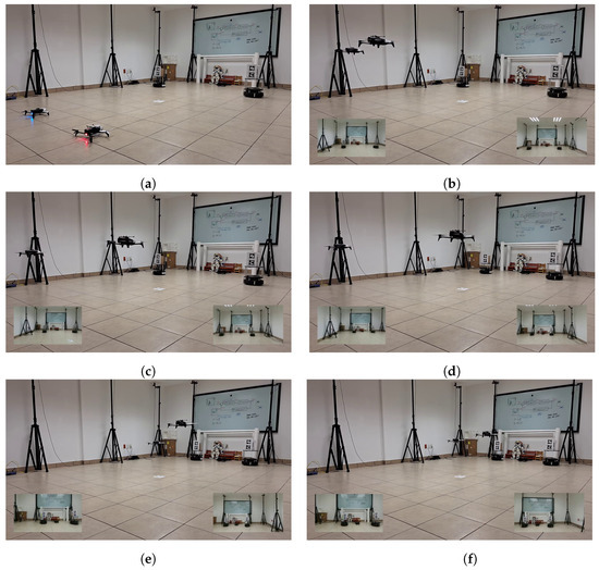
Figure 21.
Snapshots taken from a video of the experiment for the followers at different times https://youtu.be/xyGV7B5biZU (accessed on 24 July 2024). The video lasts about s. (a) At 0 s. (b) At s. (c) At s. (d) At s. (e) At s. (f) At s.
The results of this experiment are depicted in Figure 22. First, an evident behavior of several discontinuities in the velocities are shown in Figure 22a, especially up to about 29 s. These discontinuities result from the challenges that followers face in maintaining consistent bearing detection from moving ArUco markers, mainly due to issues such as image transmission errors, motion, and perturbations between the interacting drones. It should be noted that in this particular scenario, unlike the leaders’ scenario, the velocities of the system did not exhibit any saturation.
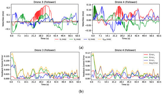

Figure 22.
Plots of important variables for the experiment with the two Bebop 2 quadrotors as followers. (a) Velocity inputs from the control law for followers (16). (b) Feedback error for the control law. (c) Normalized pixel error computed as the average error between matched points in the current and target images.
Regarding the errors in Figure 22b,c, we can notice much noise in each axis and in their average; this was caused by the noise added by the moving camera and moving target that made the current bearing noisy. Thus, when comparing the current and desired bearing at some iteration, it could be different at the next iteration, making these errors a bit noisy.
5. Conclusions and Future Work
In this work, we proposed a distributed formation control scheme that incorporated a leader–follower scheme using visual information extracted from images captured by monocular cameras. For leaders, we compared two control laws that allowed a decoupling between translational and rotational motions based on invariant features, in particular distances and inverse of distances from points projected to the unitary sphere. We found that the latter option, the inverse of distances, yielded better results in terms of generating a 3D motion closest to a straight line. For followers, a bearing-only formation approach was introduced to rely only on visual information without the need for position or velocity estimation. The feature of invariance to translation and scaling of that kind of formation approach allowed us to study a geometrical pattern formation that used the distance between the leaders to scale the formation and cross constrained spaces, such as a window. To ensure invariance, we analyzed an adequate pattern that accomplished rigidity properties, ensuring that at least two drones remained within the field of view of each new drone. In that case, the followers did not need to share information between them, and the formation could be reached with every follower using bearings measured from its onboard camera. We compared two bearing-only control laws, based on an orthogonal projection and the difference in bearings; the first one presented the advantage of yielding a smaller control effort.
For future work, some control aspects can be improved in the proposed approach, for instance, include a synchronization between both leaders and ensure the visibility of the targets to dispose of bearing measurements at each iteration. However, the loss of bearing measurements may also be due to transmission issues of image data; thus, an estimation scheme such as Kalman filtering may be used to improve the approach. We focused on the control aspects of the formation approach by facilitating the image processing aspects by using special markers. To remove these markers, other artificial vision algorithms can be used for window detection and other drones’ identification in the field of view, for instance, based on machine learning.
Author Contributions
Conceptualization, D.L.R.-P., H.M.B., C.A.T.-A. and G.A.; methodology, D.L.R.-P., H.M.B., C.A.T.-A. and G.A.; software, D.L.R.-P. and H.M.B.; validation, D.L.R.-P., H.M.B., C.A.T.-A. and G.A.; formal analysis, D.L.R.-P., H.M.B., C.A.T.-A. and G.A.; investigation, D.L.R.-P., H.M.B., C.A.T.-A. and G.A.; resources, D.L.R.-P., H.M.B., C.A.T.-A. and G.A.; data curation, D.L.R.-P. and H.M.B.; writing—original draft preparation, D.L.R.-P., H.M.B., C.A.T.-A. and G.A.; writing—review and editing, D.L.R.-P., H.M.B., C.A.T.-A. and G.A.; visualization, D.L.R.-P., H.M.B., C.A.T.-A. and G.A.; supervision, H.M.B. and G.A.; project administration, H.M.B. and G.A. All authors have read and agreed to the published version of the manuscript.
Funding
This research received no external funding.
Institutional Review Board Statement
Not applicable.
Informed Consent Statement
Not applicable.
Data Availability Statement
The complete implementation of the Gazebo simulation is available at https://github.com/deiividramirez/bearings (accessed on 24 July 2024).
Acknowledgments
The first and third authors acknowledge the financial support of the National Council for the Humanities, Science and Technology (CONAHCYT) of Mexico, under scholarships 1150332 and 943100, respectively.
Conflicts of Interest
The authors declare no conflicts of interest.
List of Symbols
The following symbols are used in this manuscript:
| Velocity vector in in the camera reference frame | |
| Transformation matrix in from the camera to the quadrotor reference frame | |
| Selection matrix in | |
| Velocity vector in in the quadrotor reference frame | |
| Bearing in between drones i and j | |
| Orthogonal projection matrix in | |
| Bearing Laplacian in | |
| Adaptive gain in | |
| Smoothness function in | |
| Invariant image feature (distance) in | |
| Linear velocity vector in | |
| Angular velocity vector in | |
| Interaction matrix in | |
| Pseudo-inverse of the interaction matrix in | |
| Sliding surface in | |
| Camera calibration matrix in | |
| Connectivity graph | |
| Leader drone | |
| Follower drone |
References
- Oh, K.K.; Park, M.C.; Ahn, H.S. A survey of multi-agent formation control. Automatica 2015, 53, 424–440. [Google Scholar] [CrossRef]
- Zhao, S.; Zelazo, D. Bearing Rigidity Theory and Its Applications for Control and Estimation of Network Systems: Life beyond Distance Rigidity. IEEE Control Syst. 2019, 39, 66–83. [Google Scholar] [CrossRef]
- Cook, J.; Hu, G. Vision-based triangular formation control of mobile robots. In Proceedings of the 31st Chinese Control Conference, Hefei, China, 25–27 July 2012; pp. 5146–5151. [Google Scholar]
- Loizou, S.G.; Kumar, V. Biologically inspired bearing-only navigation and tracking. In Proceedings of the 2007 46th IEEE Conference on Decision and Control, New Orleans, LA, USA, 12–14 December 2007; pp. 1386–1391. [Google Scholar]
- Franchi, A.; Masone, C.; Bülthoff, H.H.; Robuffo Giordano, P. Bilateral teleoperation of multiple UAVs with decentralized bearing-only formation control. In Proceedings of the 2011 IEEE/RSJ International Conference on Intelligent Robots and Systems, San Francisco, CA, USA, 25–30 September 2011; pp. 2215–2222. [Google Scholar]
- Bishop, A.N. Distributed bearing-only formation control with four agents and a weak control law. In Proceedings of the 2011 9th IEEE International Conference on Control and Automation (ICCA), Santiago, Chile, 19–21 December 2011; pp. 30–35. [Google Scholar]
- Tron, R. Bearing-Based Formation Control with Second-Order Agent Dynamics. In Proceedings of the 2018 IEEE Conference on Decision and Control (CDC), Miami Beach, FL, USA, 17–19 December 2018; pp. 446–452. [Google Scholar]
- Trinh, M.H.; Lee, B.H.; Ye, M.; Ahn, H.S. Bearing-Based Formation Control and Network Localization via Global Orientation Estimation. In Proceedings of the 2018 IEEE Conference on Control Technology and Applications (CCTA), Copenhagen, Denmark, 21–24 August 2018; pp. 1084–1089. [Google Scholar]
- Tran, Q.V.; Ahn, H.S. Flocking control and bearing-based formation control. In Proceedings of the 2018 18th International Conference on Control, Automation and Systems (ICCAS), PyeongChang, Republic of Korea, 17–20 October 2018; pp. 124–129. [Google Scholar]
- Zhao, J.; Yu, X.; Li, X.; Wang, H. Bearing-Only Formation Tracking Control of Multi-Agent Systems With Local Reference Frames and Constant-Velocity Leaders. IEEE Control Syst. Lett. 2021, 5, 1–6. [Google Scholar] [CrossRef]
- Trinh, M.H.; Zhao, S.; Sun, Z.; Zelazo, D.; Anderson, B.D.O.; Ahn, H.S. Bearing-Based Formation Control of a Group of Agents with Leader-First Follower Structure. IEEE Trans. Autom. Control 2019, 64, 598–613. [Google Scholar] [CrossRef]
- Zhao, S.; Li, Z.; Ding, Z. Bearing-Only Formation Tracking Control of Multiagent Systems. IEEE Trans. Autom. Control 2019, 64, 4541–4554. [Google Scholar] [CrossRef]
- Zhang, Y.; Wang, X.; Wang, S.; Tian, X. Distributed bearing-based Formation Control of Unmanned Aerial Vehicle Swarm via Global Orientation Estimation. Chin. J. Aeronaut. 2022, 35, 44–58. [Google Scholar] [CrossRef]
- Li, X.; Wen, C.; Chen, C. Adaptive Formation Control of Networked Robotic Systems with Bearing-Only Measurements. IEEE Trans. Cybern. 2021, 51, 199–209. [Google Scholar] [CrossRef] [PubMed]
- Su, H.; Chen, C.; Yang, Z.; Zhu, S.; Guan, X. Bearing-Based Formation Tracking Control with Time-Varying Velocity Estimation. IEEE Trans. Cybern. 2023, 53, 3961–3973. [Google Scholar] [CrossRef] [PubMed]
- Li, S.; Wang, X.; Wang, S.; Zhang, Y. Distributed Bearing-Only Formation Control for UAV-UWSV Heterogeneous System. Drones 2023, 7, 124. [Google Scholar] [CrossRef]
- Guo, D.; Leang, K.K. Image-based estimation, planning, and control for high-speed flying through multiple openings. Int. J. Robot. Res. 2020, 39, 1122–1137. [Google Scholar] [CrossRef]
- Kumar, S.; Sikander, A. A modified probabilistic roadmap algorithm for efficient mobile robot path planning. Eng. Optim. 2023, 55, 1616–1634. [Google Scholar] [CrossRef]
- Sanket, N.J.; Singh, C.D.; Ganguly, K.; Fermüller, C.; Aloimonos, Y. GapFlyt: Active Vision Based Minimalist Structure-Less Gap Detection For Quadrotor Flight. IEEE Robot. Autom. Lett. 2018, 3, 2799–2806. [Google Scholar] [CrossRef]
- Tang, Z.; Cunha, R.; Cabecinhas, D.; Hamel, T.; Silvestre, C. Quadrotor Going through a Window and landing: An image-based Visual Servo Control Approach. Control Eng. Pract. 2021, 112, 104827. [Google Scholar] [CrossRef]
- Mellinger, D.; Kumar, V. Minimum snap trajectory generation and control for quadrotors. In Proceedings of the 2011 IEEE International Conference on Robotics and Automation, Shanghai, China, 9–13 May 2011; pp. 2520–2525. [Google Scholar]
- Kermorgant, O.; Chaumette, F. Dealing With Constraints in Sensor-Based Robot Control. IEEE Trans. Robot. 2014, 30, 244–257. [Google Scholar] [CrossRef]
- Hadj-Abdelkader, H.; Mezouar, Y.; Martinet, P. Decoupled visual servoing based on the spherical projection of a set of points. In Proceedings of the 2009 IEEE International Conference on Robotics and Automation, Kobe, Japan, 12–17 May 2009; pp. 1110–1115. [Google Scholar]
- Fomena, R.T.; Tahri, O.; Chaumette, F. Distance-Based and Orientation-Based Visual Servoing From Three Points. IEEE Trans. Robot. 2011, 27, 256–267. [Google Scholar] [CrossRef][Green Version]
- Hamel, T.; Mahony, R. Visual servoing of an under-actuated dynamic rigid-body system: An image-based approach. IEEE Trans. Robot. Autom. 2002, 18, 187–198. [Google Scholar] [CrossRef]
- Chaumette, F.; Hutchinson, S. Visual servo control. I. Basic approaches. IEEE Robot. Autom. Mag. 2006, 13, 82–90. [Google Scholar] [CrossRef]
- Zhao, S.; Zelazo, D. Bearing Rigidity and Almost Global Bearing-Only Formation Stabilization. IEEE Trans. Autom. Control 2016, 61, 1255–1268. [Google Scholar] [CrossRef]
- Tron, R.; Thomas, J.; Loianno, G.; Daniilidis, K.; Kumar, V. A Distributed Optimization Framework for Localization and Formation Control: Applications to Vision-Based Measurements. IEEE Control Syst. Mag. 2016, 36, 22–44. [Google Scholar]
- Van Tran, Q.; Trinh, M.H.; Zelazo, D.; Mukherjee, D.; Ahn, H.S. Finite-Time Bearing-Only Formation Control via Distributed Global Orientation Estimation. IEEE Trans. Control Netw. Syst. 2019, 6, 702–712. [Google Scholar] [CrossRef]
- Kumar, Y.; Roy, S.B.; Sujit, P.B. Velocity Estimator Augmented Image-Based Visual Servoing for Moving Targets with Time-Varying 3-D Motion. In Proceedings of the 2021 60th IEEE Conference on Decision and Control (CDC), Austin, TX, USA, 14–17 December 2021. [Google Scholar]
- Gonzalez, T.; Moreno, J.A.; Fridman, L. Variable Gain Super-Twisting Sliding Mode Control. IEEE Trans. Autom. Control 2012, 57, 2100–2105. [Google Scholar] [CrossRef]
- Moreno, J.A.; Osorio, M. Strict Lyapunov Functions for the Super-Twisting Algorithm. IEEE Trans. Autom. Control 2012, 57, 1035–1040. [Google Scholar] [CrossRef]
- Zhao, S.; Zelazo, D. Translational and Scaling Formation Maneuver Control via a Bearing-Based Approach. IEEE Trans. Control Netw. Syst. 2017, 4, 429–438. [Google Scholar] [CrossRef]
Disclaimer/Publisher’s Note: The statements, opinions and data contained in all publications are solely those of the individual author(s) and contributor(s) and not of MDPI and/or the editor(s). MDPI and/or the editor(s) disclaim responsibility for any injury to people or property resulting from any ideas, methods, instructions or products referred to in the content. |
© 2024 by the authors. Licensee MDPI, Basel, Switzerland. This article is an open access article distributed under the terms and conditions of the Creative Commons Attribution (CC BY) license (https://creativecommons.org/licenses/by/4.0/).