Abstract
Inspired by musculoskeletal systems in nature, this paper presents a pneumatically actuated quadruped robot which utilizes two soft–rigid hybrid rotary joints in each of the four two-degrees of freedom (DoF) planar legs. We first introduce the mechanical design of the rotary joint and the integrated quadruped robot with minimized onboard electronic components. Based on the unique design of the rotary joint, a joint-level PID-based controller was adopted to control the angular displacement of the hip and knee joints of the quadruped robot. Typical gait patterns for legged locomotion, including the walking and trotting gaits, were investigated and designed. Proof-of-concept prototypes of the rotary joint and the quadruped robot were built and tested. The experimental results demonstrated that the rotary joint generated a maximum torque of 5.83 Nm and the quadruped robot was capable of locomotion, achieving a trotting gait of 187.5 mm/s with a frequency of 1.25 Hz and a walking gait of 12.8 mm/s with a gait cycle of 7.84 s. This study reveals that, compared to soft-legged robots, the quadruped robot has a simplified analytical model for motion control, size scalability and high movement speeds, thereby exhibiting significant potential for applications in extreme environments.
1. Introduction
Working in extreme conditions, including explosive, nuclear, high-voltage and magnetic-resonance environments, is a big challenge for robots. Electric-motor-driven robots have been extensively studied for their efficiency, precision, versatility and adaptability [1], including wheeled, tracked and legged robots that use electric motors as their primary power source to perform various tasks and functions. For example, fully sealed wheeled robots [2,3] use electric motors to drive the wheels for operations in chemical, radiological and nuclear missions. However, the degree of confidence decreases over time as the sealed components show different responses to vibrations, temperature, etc. In addition, tracked robots [4] that rely on electrical-motor-driven tracks have advantages over their wheeled counterparts in their load tolerances and flexible mobility on soft, slippery and rough terrains without sinking. They have been developed for use in radioactive and hazardous environments [5] and offshore oil and gas platforms [6]. However, the operating time of these robots under radioactive conditions is limited by the maximum dose that their weakest components can sustain. Compared to wheeled and tracked robots, electric-motor-driven legged robots [1,7] have the ability to make and break contact with the ground, thus navigating on challenging terrains such as rough and narrow spaces. They were built for applications in nuclear plants [8,9], oil/gas platforms [10,11] and underground mines [12], but their electronic components have a high risk of being damaged in radiation-contaminated spaces. They could cause electrical sparks and disastrous ignitions in explosive environments.
Soft-legged robots [13] powered by pneumatic actuators can be fabricated using flexible materials with minimized electronic components, and they exhibit excellent characteristics, such as inherent compliance, a good impact resistance, a high energy-to-weight ratio, safe interactions with humans and adaptability to a variety of hostile environments. For example, the untethered soft robot [14] fabricated with silicone rubbers can adapt to harsh environmental conditions, including snowstorms, fires and water, although its locomotion speed is only 0.0077 body lengths per second (BL/s). The soft quadruped robot with three degrees of freedom (DoFs) per leg [15] used simple pneumatic oscillator circuits without any electronic components to generate walking gaits for operations in environments where electronics are not suitable, but these circuits are acted on by additional control elements or based on manual input. The untethered hexapod robot in [16], with soft fluid-driven actuators composed of elastomer bladders, enabled complex deformations by leveraging viscous flows to produce non-uniform pressure between the bladders to drive the robot to move in one direction at 0.05 BL/s. Further, soft-legged robots [17,18,19] are highly flexible, and their legs may exhibit other unwanted forms of deformation, such as radial and axial expansion due to fabrication using soft materials, bringing challenges in kinematic model and motion control [20,21].
With the aim of addressing the challenges of electric-motor-driven and soft-legged robots, pneumatically actuated soft–rigid hybrid–legged robots, also known as musculoskeletal robots [22,23] and inspired by musculoskeletal systems in nature [24,25], have demonstrated promising capabilities in both building a precise kinematic model like electric-motor-driven robots and adapting to various environments like soft-legged robots. For example, with a rigid exoskeleton providing structural support and flexible pneumatic joints providing actuation and inherent mechanical compliance to absorb impacts and improve the safety in interactions with humans, soft–rigid-hybrid bipedal robots [26], quadruped robots [27], hexapod robots [24] and arthropod-like robots [22] have been proposed. These robots can achieve movement with simple gaits through manual input. In addition, despite the actuation delay and the decrease in the actuator accuracy, the quadruped robots with antagonistic pneumatic actuators developed by Tsujita [28,29] achieved stable locomotion for walking and trotting patterns by adopting an oscillator network controller and adjusting the stiffness at the trunk. The quadruped robots built by Fukuoka [30,31] can adapt to speed variations and stabilize their running pace using a neuromorphic locomotion controller with leg-loading feedback. However, human assistance was needed during the experiments to prevent the robots from falling over. Despite having great potential, soft–rigid hybrid-legged robots are a new trend in robotics and have not been thoroughly investigated [32]. One of the main limitations is that the development of legged robots using pneumatic actuators is complicated.
To further explore the potential of soft–rigid hybrid robots for operations in special environments, this paper proposes a soft–rigid hybrid rotary joint and develops a pneumatically actuated quadruped robot integrating a rectangular torso and four 2-DoF planar robot legs. The main contributions of this work include the mechanical design and experimental evaluation of a soft–rigid hybrid rotary joint, and the development of an integrated quadruped robot and validation of its feasibility in typical gait control.
In the following sections, we first introduce the rotary joint design, quadruped robot integration and controller development. The foot trajectories and typical gaits of the quadruped robot were also investigated. Following this process, Section 3 presents a torque test of a single rotary joint and demonstrates the trotting and walking gaits of the quadruped robot. Section 4 provides a detailed discussion of this work, and Section 5 concludes the paper.
2. Development of the Pneumatically Actuated Quadruped Robot
2.1. Design of the Soft–Rigid Hybrid Rotary Joint
The variable-stiffness actuators for soft robots were developed by using antagonistic fluidic actuation [33]. For example, the theoretical models of the antagonistic rotary joints in [34,35] indicated that, given an angular displacement/torque, the torque/angular displacement is linear with the pressure difference between the two muscles, and the stiffness is related to the sum of the pressures of the two muscles. However, the hinge function of the rotary joint in [34] may decline when the chambers are inflated to the fully deployed state for a long time. The maximum contraction ratio of the McKibben artificial muscle in [35] is only between 20% and 30%.
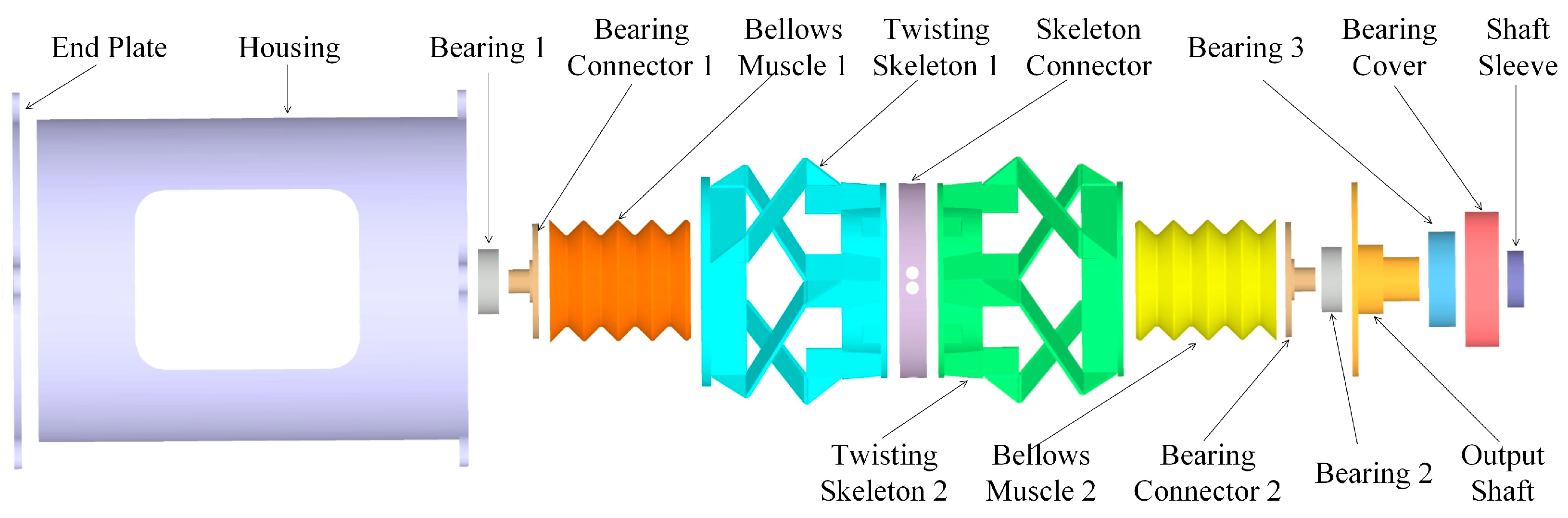
Inspired by the antagonistic fluidic actuation, we proposed a soft–rigid-hybrid rotary joint based on the twisting actuator developed in our previous work [36], as illustrated in Figure 1. Two twisting skeletons were connected to the skeleton connector, where one performed a clockwise helical motion and the other produced an anticlockwise helical motion. A soft bellows muscle was coupled to the twisting skeleton with a bearing and a bearing connector. The bellows muscle can be vacuumed and inflated, thereby generating linear driving force to actuate the twisting skeleton. The left end of twisting skeleton 1 was fixed to the end plate, while the right end of twisting skeleton 2 was connected to the output shaft. The outer ring of bearing 3 was fixed to the housing via a bearing cover. The linear motion of the output shaft was restricted by the inner ring of bearing 3 and the shaft sleeve. Therefore, the rotary joint generated pure rotation and torque at the output shaft by adjusting the pressures supplied to the two bellows muscles.
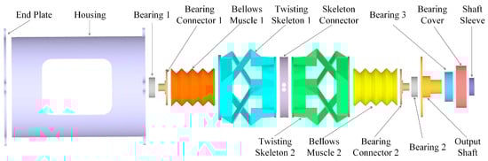
Figure 1.
Exploded view of the soft–rigid hybrid rotary joint.
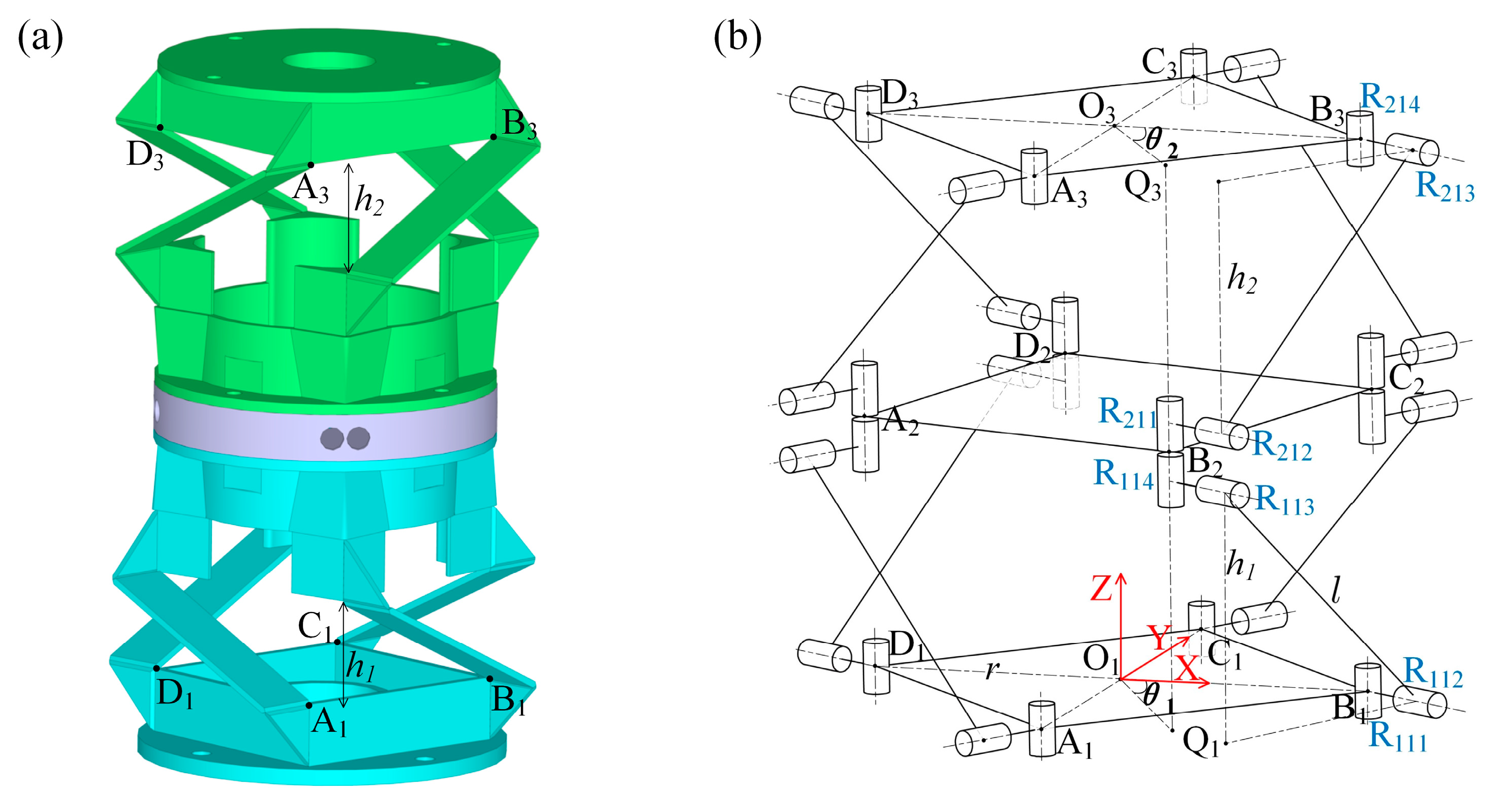
The two twisting skeletons of the rotary joint are illustrated in Figure 2a. The kinematic structure is shown in Figure 2b. The base, the middle platform and the upper platform are parallel and denoted by identical squares □A1B1C1D1, □A2B2C2D2 and □A3B3C3D3, respectively, with a radius of r. The angular displacement of the middle platform, corresponding to the base of twisting skeleton 1, is denoted by θ1. It can be measured between lines O1B1 and O1Q1, where Q1 is the projection of vertex B2 on the base. In addition, the link connecting the revolute joints R112 and R113 is denoted as L11 and its length is defined by the distance, l, between the two parallel joint axes. The length of the projection of L11 in the direction of O1O3 is denoted by h1. Similarly, the angular displacement of the upper platform of twisting skeleton 2 is denoted by θ2. It is measured between lines O3B3 and O3Q3, where Q3 is the projection of vertex B2 on the upper platform. The length of the projection of the link L21, connecting the revolute joints R212 and R213 in the direction of O1O3, is denoted by h2. The angular displacement of the rotary joint, defined as θ, is calculated using the following equation:
where
and the sum of h1 and h2 is constant.

Figure 2.
(a) A 3D model and (b) kinematic structure of the twisting skeletons of the rotary joint.
2.2. Integration of the Quadruped Robot
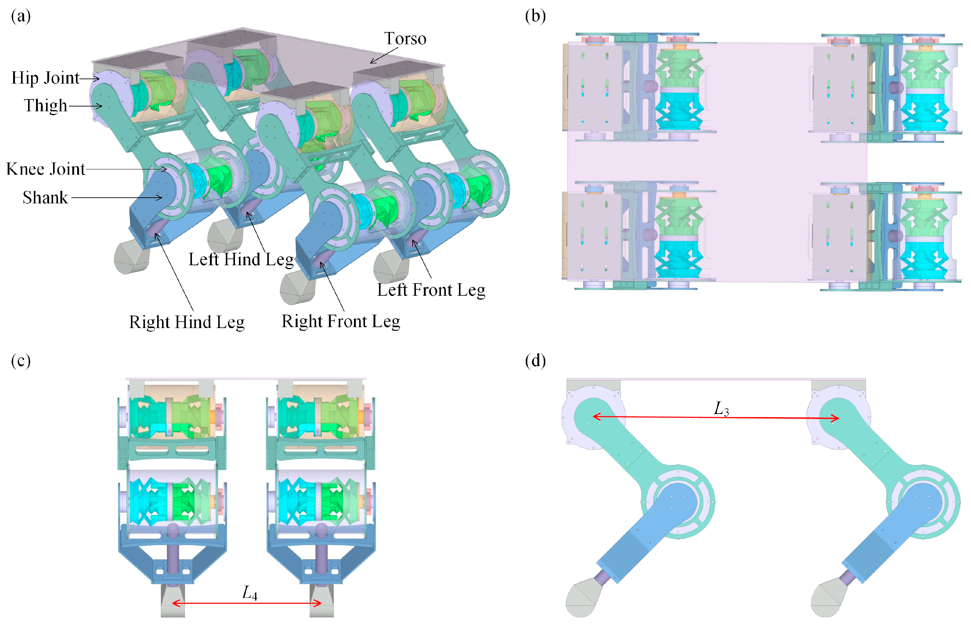
Using two rotary joints as the hip and knee joints, a planar robot leg with 2 DoFs was designed. The thigh consisted of a beam and two plates, where one plate connected the output shaft of the hip joint and the housing of the knee joint, and the other plate, rotating freely around the hip joint, provided structural support for the knee joint. The shank had a similar design to the thigh to support and drive the foot.
The quadruped robot consisted of a torso and four 2-DoF robot legs, as shown in Figure 3. The torso of the robot was a rigid rectangular plate. The four legs were fixed to the torso symmetrically. The design specification of the quadruped robot is listed in Table 1.
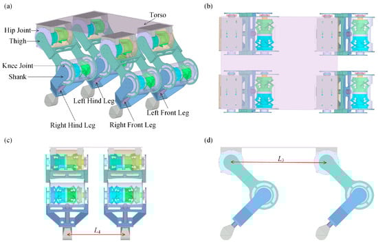
Figure 3.
The 3D design of the pneumatically actuated quadruped robot. (a) Isometric view. (b) Top view. (c) Left view. (d) Front view.

Table 1.
Design specification of the quadruped robot.
2.3. Controller for the Soft–Rigid Hybrid Rotary Joint
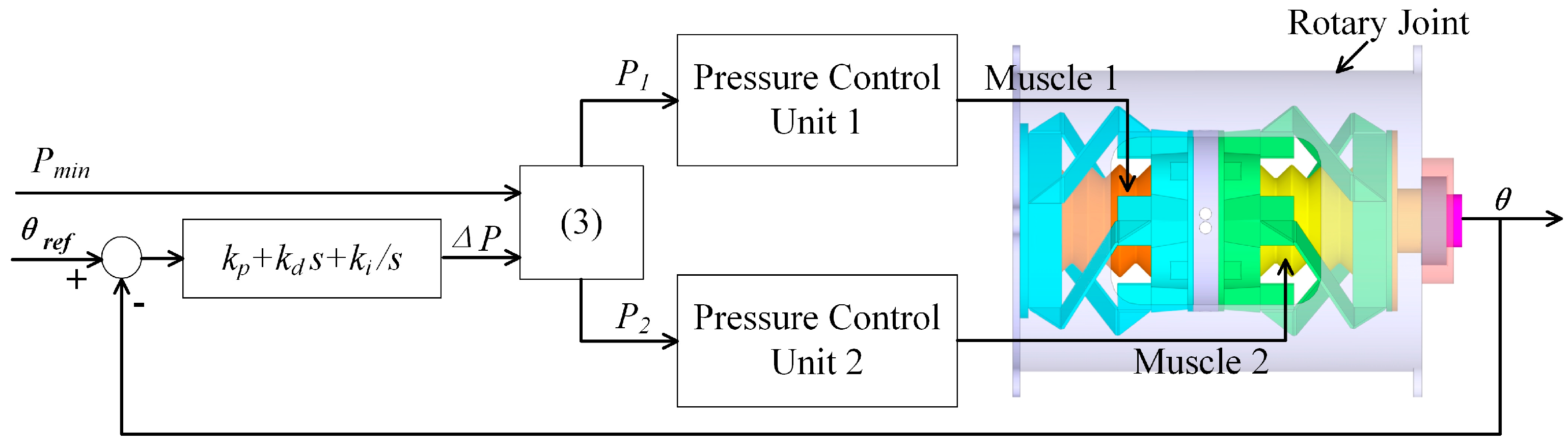
The angular displacement of the rotary joint mainly depends on the pressure difference between the two bellows muscles due to the compliance of bellows muscles and the flexure hinges of the twisting skeletons. The larger the pressure difference is, the larger the angular displacement of the rotary joint is. Based on this characteristic, a joint-level PID-based controller was adopted to achieve the active angular displacement control, as shown in Figure 4. Using the reference angular displacement θref as the controller’s input and the real-time angular displacement θ of the rotary joint as the feedback signal, the error between the reference angular displacement and the real-time angular displacement is calculated and transmitted to a PID module. The desired pressure difference ΔP is set as the output of the PID module. By combining the minimum pressure Pmin, which is directly set from an external port by users, the theoretical pressures P1 and P2 of the two bellows muscles are determined using Equation (3) and transferred to the pressure control units, which control the pressure supplied to the two bellows muscles of the rotary joint by using the pneumatic regulators and solenoid valves. In addition, the values of the PID parameters were tuned manually by lifting the quadruped robot and evaluating the response of each joint to a step input, while Pmin was set to 30 kPa for the robot’s experiments.
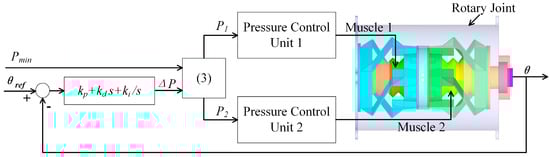
Figure 4.
The PID-based controller of the rotary joint for the angular displacement control.
2.4. Gait Analysis
Quadruped robots can implement various gaits, such as crawling, walking, trotting, pacing and bounding gaits, which determine how the robot moves and interacts with the environment. The typical gaits are different in their sequences as well as the duration that each leg is in contact with the ground.
To generate periodic gaits, the phase is used to depict the state of each leg in a gait cycle, and the duty cycle is denoted by to represent the percentage of the gait cycle during which the leg is in contact with the ground. At the start of the gait cycle, each leg starts in the stance state with a phase of The leg switches from the stance state to the swing state when increases to . Once the phase increases to the maximum value of 1, it wraps around to zero, and the leg switches from the swing state back to the stance state, starting the next gait cycle. The phase of the i-th leg can be calculated using the equation:
where t is the current time; ti,0 is the start time of the current gait cycle of the i-th leg; and T is the period of one gait cycle. For higher velocities, a smaller gait period T is more suitable. With a constant gait period T, a smaller duty cycle d would result in each leg having an increased aerial time, creating a more dynamic gait. Note that the four legs may have different values of ti,0 and .
In addition, the phase offset is defined to coordinate the phase of the i-th leg with respect to the phase of the leading leg to produce different gait patterns through the relationship:
Table 2 lists the duty factors and desired phase offsets for defining typical gaits, including the crawling, walking, trotting, pacing and bounding gaits. Based on the parameters given in Table 2, Figure 5 lists the sequences of the leg movements with the trotting and walking gaits. The solid-blue-colored bars indicate the stance phase of the corresponding leg, while the white-colored bars represent the swing phase of the corresponding leg. In the trotting gait, two diagonally opposite legs (e.g., the right front and left hind legs) are in contact with the ground while the other two legs are lifted and move forward. In the walking gait, a leg in the air is set down at the same instant as another leg is lifted, and three legs contact the ground at all times.
Table 2.
The duty factors and desired phase offsets of the typical gaits, including the crawling, walking, trotting, pacing and bounding gaits, for the left hind leg (LH), left front leg (LF), right front leg (RF) and right hind leg (RH).
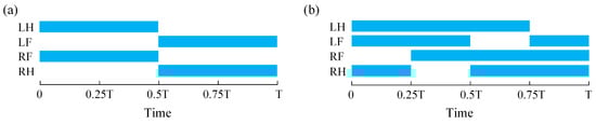
Figure 5.
Sequences of the leg movement with typical gaits in one gait cycle. (a) Trotting gait. (b) Walking gait. The solid-blue-colored bars indicate the stance phase of the corresponding leg, while the white-colored bars represent the swing phase of the corresponding leg. (LH: the left hind leg; LF: the left front leg; RF: the right front leg; and RH: the right hind leg.)
2.5. Foot Trajectory
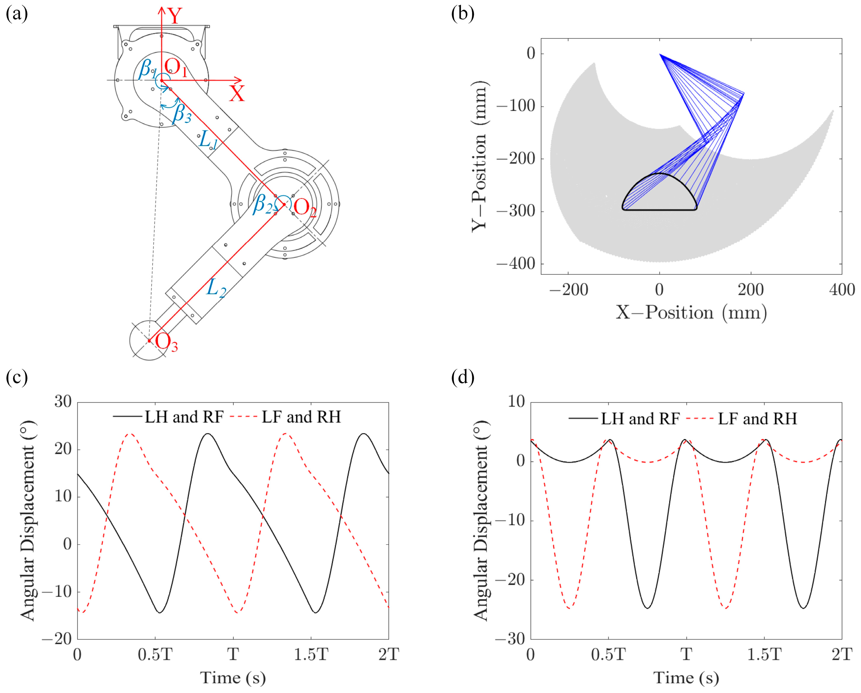
As illustrated in Figure 6a, a coordinate frame O1–XYZ was set at the leg where the origin was located at the center of the hip joint O1; the X-axis was horizontal and the Y-axis was vertical. Based on the Denavit–Hartenberg method, the position of the foot O3,, expressed in O1–XYZ can be derived as:
where , , and are the length of the thigh, the length of the shank, the angle of the hip joint and the angle of the knee joint, respectively. The inverse kinematics can be solved based on the conventional geometric approach. For a given position of the foot, the angles of the hip and knee joints are derived as:
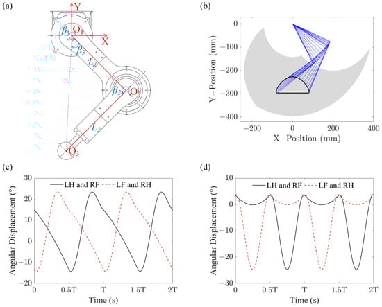
Figure 6.
Leg movement of the quadruped robot with the trotting gait. (a) Schematic diagram of the 2-DoF robot leg. (b) Foot trajectory of the quadruped robot with the trotting gait. (c) Angular displacement of the hip joints of the quadruped robot with the trotting gait. (d) Angular displacement of the knee joints of the quadruped robot with the trotting gait. (LH: the left hind leg; LF: the left front leg; RF: the right front leg; and RH: the right hind leg.)
One gait cycle of the foot can be divided into a stance phase and a swing phase. To minimize the impact between the ground and the foot, the foot trajectory should meet the demand that the velocity and acceleration of the foot along the direction of the Y-axis (Figure 6a) become zero at the time of touchdown, liftoff and the maximum foot height [37]. In addition, the legs support the torso to move forward during the stance phase. To make the torso move steadily, the acceleration of the foot along the direction of the X-axis shown in Figure 6a needs to be as small as possible. Therefore, the foot trajectory in the swing phase can be composed of a cubic curve along the X-direction and a cosine curve along the Y-direction, while the foot trajectory in the stance phase can be a straight line along the X-direction [38]. The equations for defining the foot trajectory with respect to the coordinate frame O1–XYZ, set at the center of the hip joint, are:
where
Ls denotes the stride length; represents the remainder of the real-time divided by the gait cycle T; Lt denotes the distance between the axis of symmetry of the foot trajectory and the hip joint; and Ht and Hf represent the height of the hip joint and the maximum height of the foot in the Y-axis with respect to the ground, respectively. Equations (10) and (11) represent the position variation in the foot along the X- and Y-axes during the stance phase, respectively, while Equations (12) and (13) represent its position variation along the X- and Y-axes during the swing phase, respectively.
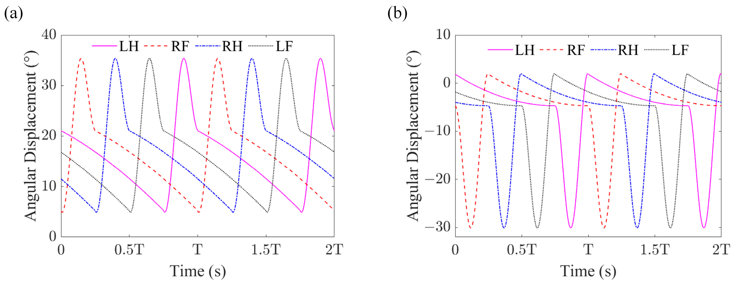
To evaluate the dynamic performance of the quadruped robot, the trotting and walking gaits were chosen for the experiments. The parameters T = 0.8 s, Ht = 297 mm, Hf = 70 mm, Ls = 150 mm and Lt = 0 mm were set for the trotting gait. Figure 6b shows the foot trajectory of the quadruped robot with the trotting gait, while Figure 6c,d illustrate the theoretical angular displacements of the hip and knee joints of the quadruped robot with the trotting gait, respectively. (The angular displacements of 0° in Figure 6c,d correspond to and shown in Figure 6a, respectively.) In contrast, the parameters T = 7.84 s, Ht = 285 mm, Hf = 80 mm, Ls = 100 mm and Lt = 50 mm were set for the walking gait. Figure 7a,b illustrate the theoretical angular displacements of the hip and knee joints of the quadruped robot with the walking gait, respectively.
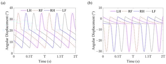
Figure 7.
Leg movement of the quadruped robot with the walking gait. (a) Angular displacement of the hip joints of the quadruped robot with the walking gait. (b) Angular displacement of the knee joints of the quadruped robot with the walking gait. (LH: the left hind leg; LF: the left front leg; RF: the right front leg; and RH: the right hind leg.)
3. Experimental Evaluation of the Rotary Joint and Integrated Quadruped Robot
To evaluate the performance, prototypes of the rotary joint and the quadruped robot were fabricated using 3D printing and CNC approaches to achieve rapid and low-cost manufacturing. TPU 95A filaments were selected as the material for printing the soft bellows muscles of the rotary joint due to their exceptional wear-and-tear resistance and rubber-like flexibility. The thighs, shanks and housings of the rotary joints were 3D-printed with the PLA material. The twisting skeletons of the rotary joints were CNC-machined using multi-layered aluminum composite panels (HYLITE) with a polypropylene core and aluminum cover layers, which have good fatigue resistance and can provide a compliant hinge function to withstand repeated bending without damage. The feet were fabricated by injecting Dragon Skin 30 into prefabricated molds. The torso was cut with a carbon fiber plate. The quadruped robot prototype was obtained by assembling the modularized rotary joints and aforementioned components.
3.1. Torque Evaluation of the Soft–Rigid Hybrid Rotary Joint
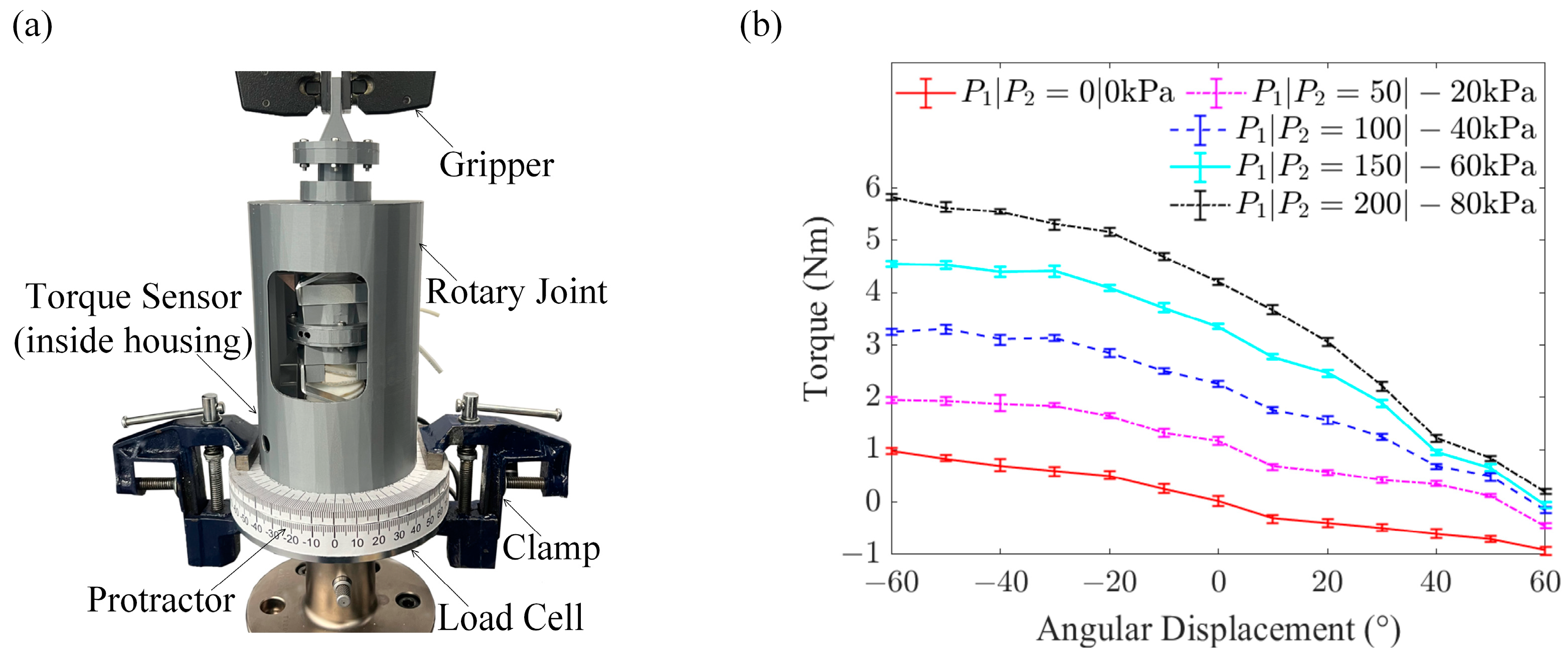
Figure 8a illustrates the prototype of the rotary joint and experimental settings for evaluating its output torque. The base of the rotary joint was mounted on the load cell of the testing platform (E5967, Instron, Norwood, MA, USA) by using two clamps, while the output shaft of the rotary joint was fixed to the gripper of the Instron machine. A 6-axis torque-force sensor (RFT40-SA01, ROBOTOUS, Seongnam-si, Korea) was installed between the twisting skeletons and the base of the rotary joint to measure its output torque.
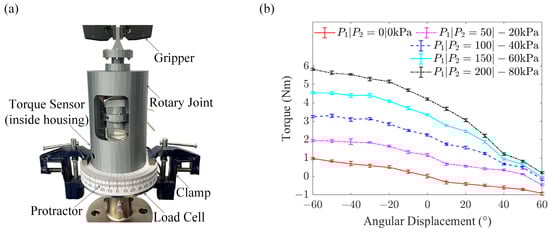
Figure 8.
Torque evaluation of the soft–rigid-hybrid rotary joint. (a) Testing platform. (b) Output torque of the rotary joint.
The output torque of the rotary joint was tested by fixing the rotary joint and maintaining the bellows muscles at constant pressures. As the rotary joint was symmetrical, the cases of P1≥0 and P2≤0 were evaluated in this work. The experimental results in Figure 8b reveal that, without actuating the two bellows muscles (P1 = P2 = 0 kPa), the absolute value of the output torque increased when the rotary joint deviated from its initial position of θ = 0°, which resulted from the compliance of the bellows muscles and the flexure hinges of the twisting skeletons. Given a certain angular displacement, increasing the pressure of bellows muscle 1 from 0 to 200 kPa and decreasing the pressure of bellows muscle 2 from 0 to −80 kPa led to increased torque of the rotary joint, but the torque change in the rotary joint at an angular displacement of θ > 0° was lower than that at an angular displacement of θ < 0°. The reason is that, when the angular displacement increased from 0° (θ > 0°), bellows muscle 1 was extended, and its contact area with twisting skeleton 1 decreased; bellows muscle 2 was contracted, and its inner space decreased. Inflating bellows muscle 1 and vacuuming bellows muscle 2 at an angular displacement of θ > 0° generated a lower force than that at an angular displacement of θ < 0° to drive the twisting skeletons. Further, the rotary joint was capable of generating a maximum torque of 5.83 Nm under the conditions of θ = −60°, P1 = 200 kPa and P2 = −80 kPa.
3.2. System Integration
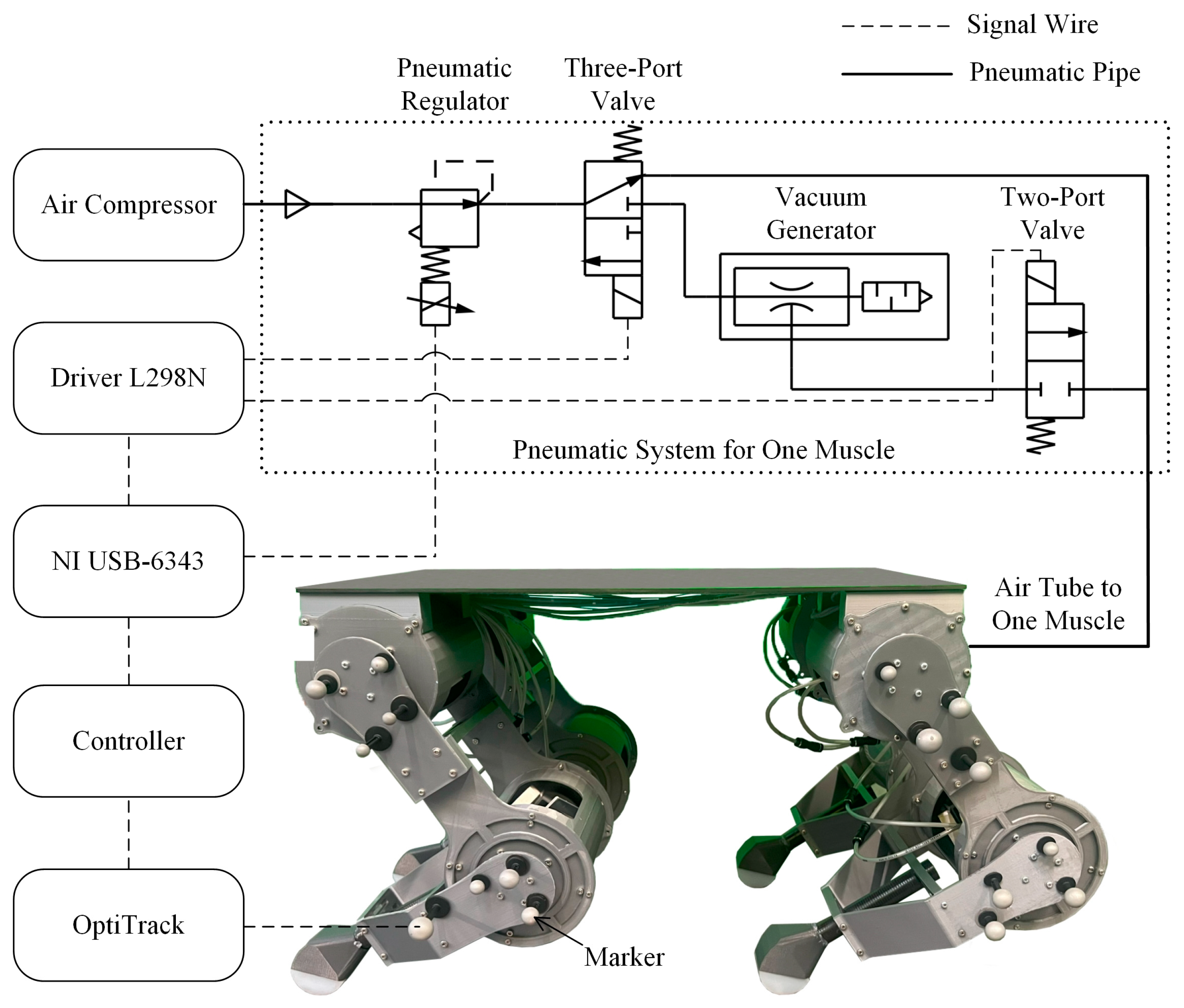
The quadruped robot was tethered, and the pneumatic and control systems were off-board to reduce the weight of the quadruped robot. A PID-based controller was adopted for the rotary joints to achieve active angular displacement control, which was developed using Matlab 2023® on a desktop computer. The bellows muscles of the rotary joints were capable of being both inflated and vacuumed, and their pressures were adjusted by the pneumatic system, which was composed of an air compressor, pneumatic regulators (ITV-212BL4, SMC, Tokyo, Japan), three-port solenoid valves (VDW350-5G-4-02F-Q, SMC, Tokyo, Japan), two-port solenoid valves (VX220AGA, SMC, Tokyo, Japan) and vacuum generators (ZH07DSA-06-06-06, SMC, Tokyo, Japan), as shown in Figure 9. The data acquisition device (USB-6343, National Instruments, Austin, TX, USA) was connected to the computer for transmitting control commands from the controller to the corresponding valves. The data acquisition device directly controlled the pneumatic regulators via analogue output, while the two-port and three-port solenoid valves were driven by the motor driver controllers L298N. (When receiving digital signals from the data acquisition device, the motor driver controller L298N generated analogue signals to control the solenoid valves.) Markers were attached to the thigh and the shank of each leg to measure the angular displacements of the hip and knee joints via the motion capture system (Prime Cameras, OptiTrack, Corvallis, OR, USA), respectively. This information was fed back to the controller to realize the closed-loop control of the posture of the quadruped robot.
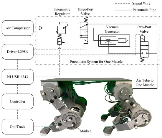
Figure 9.
Pneumatic and control systems of the quadruped robot.
3.3. Trotting Gait Test of the Quadruped Robot
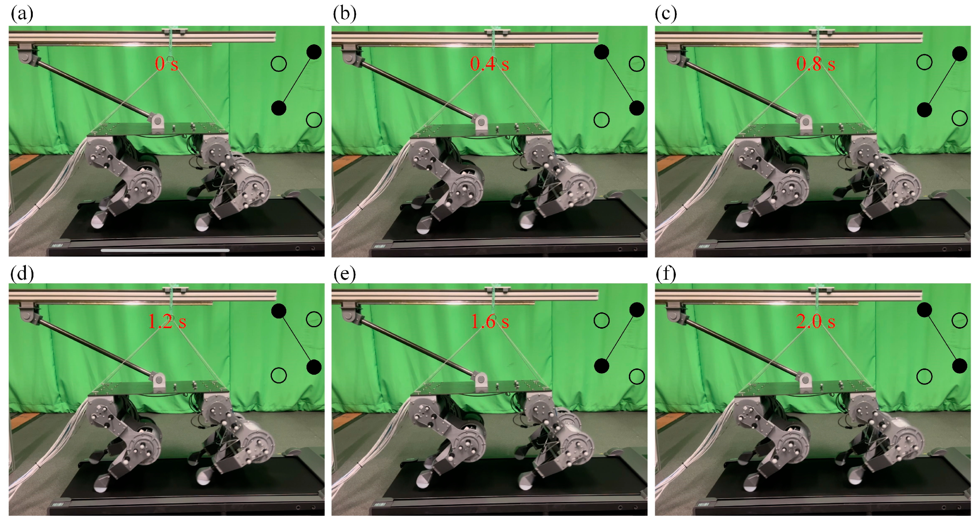
To prevent the quadruped robot from falling sideways during the tests, one end of a linkage was connected to the torso of the quadruped robot with a revolute joint, and the other end of the linkage was connected to a guide carriage with a revolute joint. The guide carriage had one DoF and was capable of moving on the guide rail. In addition, to prevent the quadruped robot from radically rolling forwards and backwards, the torso of the quadruped robot was connected to strings. The other ends of the strings were tied to a linear guide block, which could move along the linear slide rail. Using the theoretical trajectories shown in Figure 6c,d as inputs, the trotting gait of the quadruped robot at 187.5 mm/s (0.36 BL/s) and a frequency of 1.25 Hz was tested on a treadmill (Supplementary Video S1). As illustrated in Figure 10, the moving sequences of the quadruped robot with the trotting gait were as follows: left front and right hind legs lift synchronously; left hind and right front legs lift synchronously; and left front and right hind legs lift synchronously, which matches the sequences depicted in Table 2 and Figure 5a. As we controlled the position instead of the torque of the supporting legs in the stance phase in the experiments, the elastic properties of the robot legs were not fully explored and the strings connecting the quadruped robot were constantly under tension.
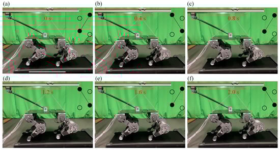
Figure 10.
Moving sequences of the four legs of the quadruped robot with the trotting gait. Left front and right hind legs lift synchronously in (a,c,e). Left hind and right front legs lift synchronously in (b,d,f). Solid circles denote the feet in contact with the ground. White circles denote lifting feet.
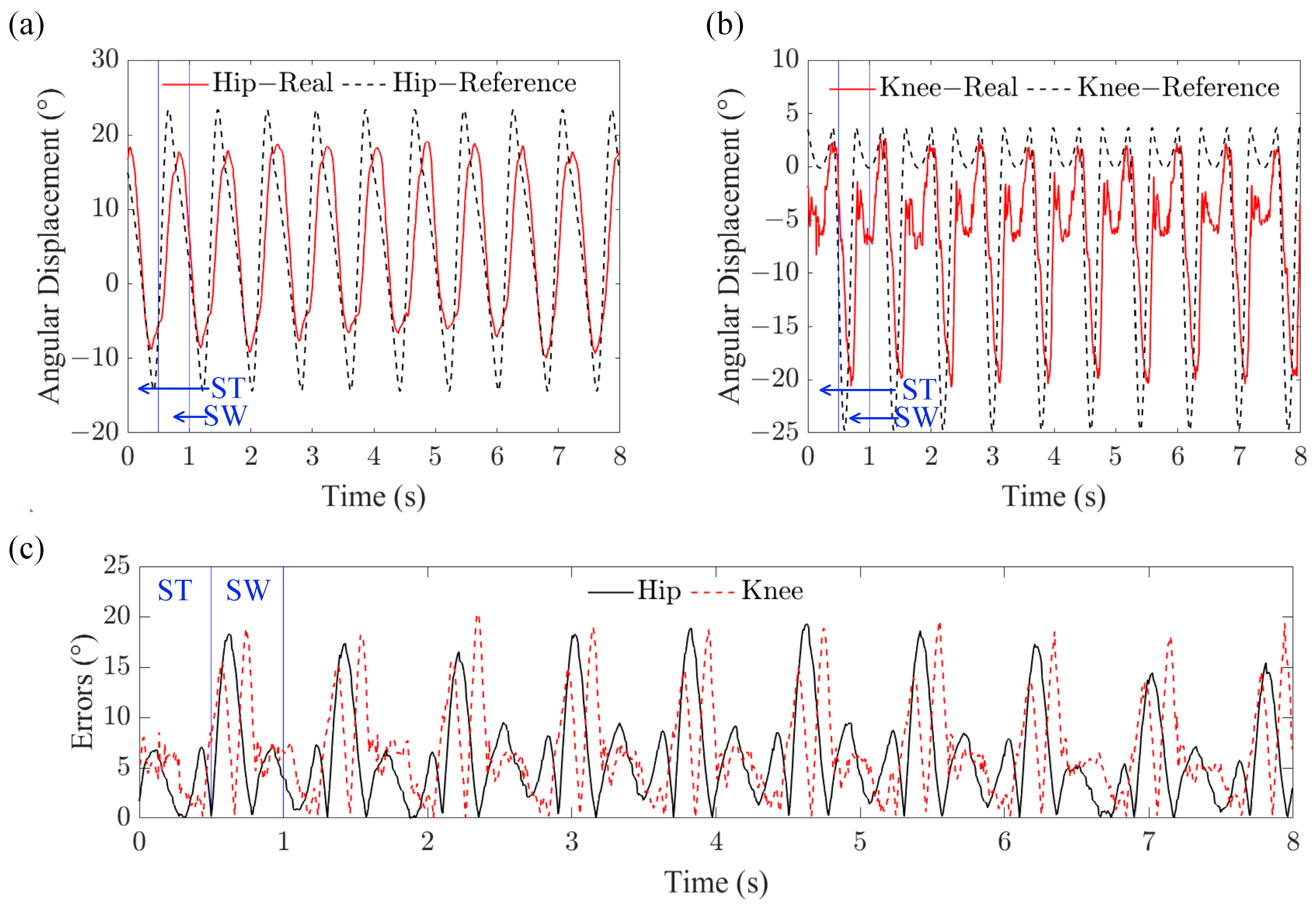
Further, as the movements of the four legs of the quadruped robot with the periodic trotting gait were similar, the left hind leg was selected for the analysis. The angular displacements of the hip and knee joints of the left hind leg with the trotting gait, as shown in Figure 11a,b, illustrate that both the hip and knee joints of the left hind leg closely followed the reference trajectories. The errors in the angular displacements of the hip and knee joints are depicted in Figure 11c. This figure shows that the error in the swing phase was significantly larger than that in the stance phase because the swing legs freely moved in the air without any restriction from the ground, and other factors such as the sharp changes in the reference trajectories and the delay in the pneumatic pressure supply also negatively affected the results. In spite of the errors, Figure 10 and Supplementary Video S1 demonstrate that the quadruped robot with the trotting gait was capable of smooth locomotion.
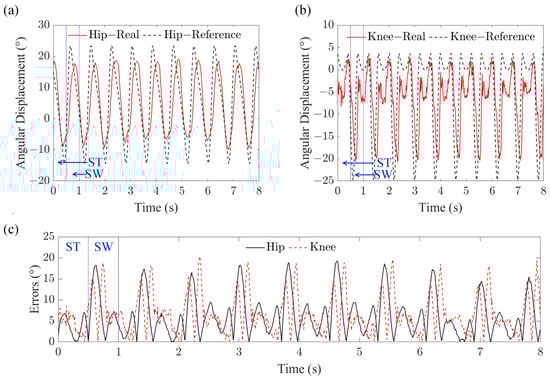
Figure 11.
Movement of the left hind leg of the quadruped robot with the trotting gait. (a) Angular displacement of the hip joint of the left hind leg. (b) Angular displacement of the knee joint of the left hind leg. (c) Errors in the angular displacements of the hip and knee joints of the left hind leg. (ST: stance phase; SW: swing phase.)
3.4. Walking Gait Test of the Quadruped Robot
By setting the theoretical trajectories shown in Figure 7a,b as the inputs, the walking gait of the quadruped robot at 12.8 mm/s and a gait cycle of 7.84 s was tested without using a treadmill (Supplementary Video S1). As illustrated in Figure 12, the moving sequences of the quadruped robot with the walking gait were as follows: left front leg lift; left hind leg lift; right front leg lift; right hind leg lift; and left front leg lift, which matches the sequences depicted in Table 2 and Figure 5b. Supplementary Video S1 illustrates that the robot legs sometimes slipped when they lifted off the ground (switched from the stance phase to the swing phase). This is because only one set of PID parameters was used to control the angular displacements of the hip and knee joints of the quadruped robot. (The robot in [32] was able to move without assistance by using two sets of PID parameters to control the legs in the swing phase and the stance phase, respectively, but its movement was clumsy.) In addition, to minimize the impact between the ground and the foot, the velocity and acceleration of the foot along the direction of the Y-axis were set to zero at the time of liftoff, so that the foot did not generate a high force to kick the ground.
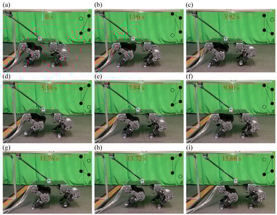
Figure 12.
Moving sequences of the four legs of the quadruped robot with the walking gait. (a) Left front leg lift. (b) Left hind leg lift. (c) Right front leg lift. (d) Right hind leg lift. (e) Left front leg lift. (f) Left hind leg lift. (g) Right front leg lift. (h) Right hind leg lift. (i) Left front leg lift. Solid circles denote the feet in contact with the ground. White circles denote lifting legs.
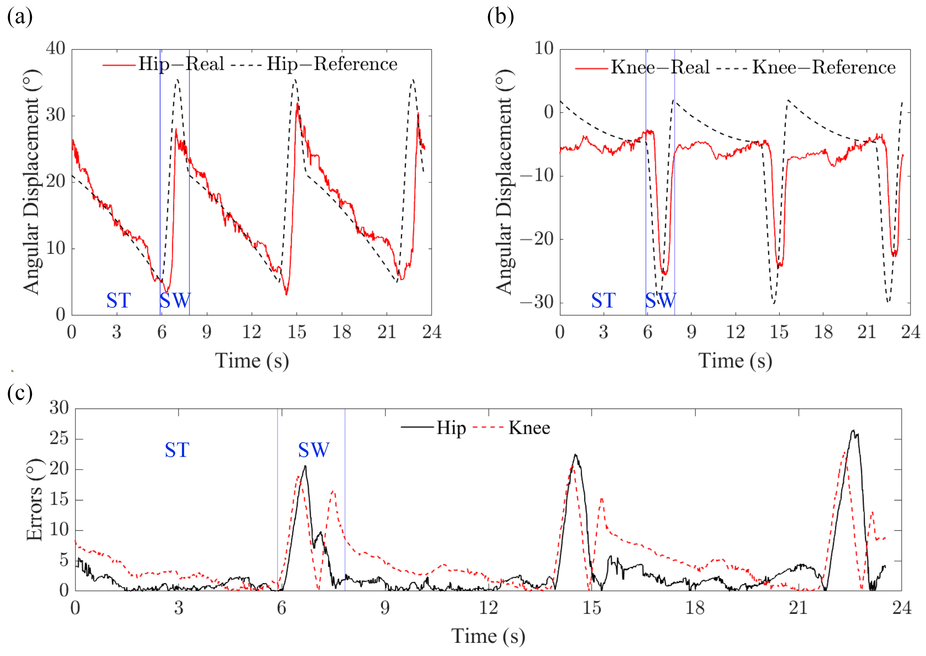
Similar to the trotting gait test, the left hind leg was selected for the tracking performance analysis. The angular displacements of the hip and knee joints of the left hind leg with the walking gait, as shown in Figure 13a,b, illustrate that both the hip and knee joints of the left hind leg were able to follow the reference trajectories. Figure 13c depicts that the errors in the hip and knee joints mainly occurred at the peaks and troughs of the reference trajectories in the swing phase, and were caused by the sharp changes in the inputs and the actuation delay.
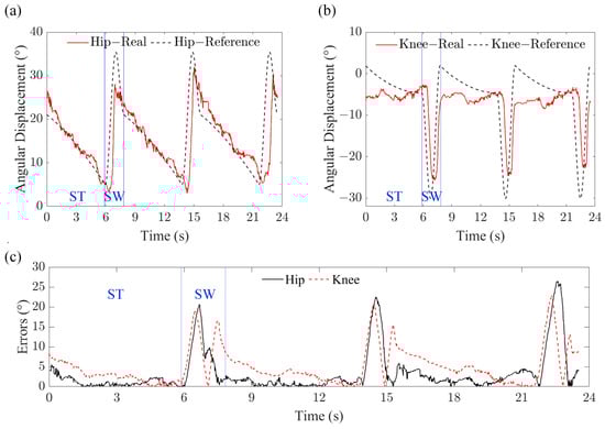
Figure 13.
Movement of the left hind leg of the quadruped robot with the walking gait. (a) Angular displacement of the hip joint of the left hind leg. (b) Angular displacement of the knee joint of the left hind leg. (c) Errors in the angular displacements of the hip and knee joints of the left hind leg. (ST: stance phase; SW: swing phase.)
Further, Table 3 reveals that the proposed quadruped robot has a more simplified kinematic model for motion control and is capable of higher locomotion speeds than soft-legged robots. In addition, compared to existing soft–rigid hybrid–legged robots, the locomotion speed of the proposed quadruped robot is competitive, and is only slower than the soft–rigid hybrid–legged robot driven by McKibben-type pneumatic artificial muscles [31]. However, the McKibben-based robot is complicated, since one leg has three joints with two external muscles actuating each joint; the distribution of McKibben artificial muscles needs to be specifically designed; and the robot’s initial configuration is complex to adjust. In contrast, using a rotary joint with embedded pneumatic muscles as a module, the quadruped robot developed in this paper has a concise and compact structure and can be quickly adjusted.
Table 3.
Comparison of the quadruped robot with existing soft and soft–rigid hybrid robots.
4. Discussion
In this paper, a gait generator was used to generate typical gaits to coordinate the movement sequences of the different legs of a quadruped robot, and a joint-level PID-based controller was adopted to control the angular displacements of the hip and knee joints. The feasibility of gait control in the quadruped robot was demonstrated, although the preliminary experiments illustrated that the quadruped robot slipped sometimes, exhibited large tracking errors in the swing phase and needed assistance during movement, including the linkage and strings presented in Section 3.3. To eliminate the undesirable oscillatory behavior and realize stable movements of the quadruped robot without any assistance, control strategies, such as active model-based control [39], adaptive fuzzy sliding mode control [40] and reinforcement learning-based control [41], for predicting unknown disturbances and improving the tracking performance of pneumatic artificial muscles with uncertainty and a considerable delay in characteristics will be further investigated. In addition, advanced controllers used in electrical-motor-driven robots, such as a torque control for adjusting the ground reaction force of the supporting legs [42] and a closed-loop central pattern generator for leveraging the compliance of elastic legs [43], could be considered for controlling the pneumatically actuated quadruped robot in the future.
Moreover, variable stiffness is an essential characteristic of robots for safe physical human–robot interactions and adaptation to various environments and applications [44]. Variable-stiffness actuators for rigid-bodied robots have been developed by connecting motors to adjustable springs [45,46], by building virtual controllers for motors [47,48] or by combining both [49]. In contrast, the variable-stiffness actuators for soft robots can be developed by using a pair of antagonistic muscles [33]. For example, the rotary joints reported in [34,35] had variable stiffness, which could be adjusted by controlling the internal pressures of the two antagonistic muscles without changing their position. The proposed rotary joint with two antagonistic bellows muscles has a similar arrangement to that described in [34,35], and our previous work in [50] demonstrated that a bellows muscle is equivalent to a non-linear spring and the muscle can adjust its stiffness by changing its internal pressure. Hence, the proposed rotary joint has the potential for variable stiffness. How to derive the theoretical model of the output torque and the stiffness of the proposed rotary joint and make use of it for highly dynamic motions of the quadruped robot will be explored in our future work.
It is worth mentioning that pneumatic actuating systems composed of an air compressor, regulators and solenoid valves are normally heavy and bulky. Like most pneumatically actuated robots [27,28,29,30,31,32], in this work, the pneumatic actuation system was off-board, and the robot was tethered to make the robot lightweight. Though pneumatic robots without an external power source have recently been developed, as reported in the references [14,15], lightweight mini air compressors and valves bring in additional challenges, including a small volume of compressed gas, a low flow rate, a limited operating pressure and imprecise pressure control. In addition, the maximum output torque of the rotary joint used for the quadruped robot depended on its maximum operating pressure of 250 kPa, which was determined from the material selection and the fabrication approach. In contrast, the maximum pressures of pneumatically actuated robots were 110 kPa in [20], 152 kPa in [14], 170 kPa in [15] and 400 kPa in [30,31]. How to improve the airtightness and durability of the bellows muscle used in this paper is worth investigating.
Further, the experiments in Section 3 show that the quadruped robot was capable of moving with a trotting gait at 187.5 mm/s and a frequency of 1.25 Hz. Compared to existing electrical-motor-driven robots [51], the moving speed of the proposed quadruped robot was relatively low, and it was limited to some extent by the weight of the legs. This can be improved by concentrating all the rotary joints at the torso and actuating the knee joints with cables. For example, the ScarlETH robot [42] used chain and cable pulley systems to locate the actuators directly at the hip joints to facilitate a fast leg motion and reduce the energy losses in impact collisions. The MIT Cheetah [52] actuated the knee joints through a parallel linkage, thereby minimizing the mass and inertia of the legs and maximizing impact mitigation. Similar designs will be considered in our later research.
5. Conclusions
This study developed a soft–rigid hybrid rotary joint and its evolved 2-DoF planar robot leg for a pneumatic quadruped robot. With CNC-machined twisting skeletons using aluminum composite panels and 3D-printed bellows muscles using TPU 95A material, the rotary joint generated a maximum torque of 5.83 Nm. By using a simplified PID-based controller to coordinate the angular displacements of the hip and knee joints, the quadruped robot’s feasibility in typical gait control was evaluated. The experimental results demonstrated that the quadruped robot was capable of movement with a trotting gait at 187.5 mm/s (0.36 BL/s) and a frequency of 1.25 Hz, and a walking gait at 12.8 mm/s and a gait cycle of 7.84 s. The quadruped robot has a more simplified kinematic model for motion control and is capable of a higher movement speed than conventional soft-legged robots. The rotary joint with embedded pneumatic muscles led to a more compact structure of the robot leg. Further, the simplified kinematic model allows more precise configuration adjustment compared to existing soft–rigid hybrid–legged robots driven by McKibben pneumatic artificial muscles, as shown in Table 3. Further, this study paves the way for the development of soft–rigid hybrid–legged robots with minimized onboard electronics for applications in environments where electrical-motor-driven robots may not be suitable, such as in nuclear, explosive and magnetic-resonance environments.
Supplementary Materials
The following supporting information can be downloaded at: https://youtu.be/Bgd0uzYrjWU (accessed on 22 January 2024), Video S1: experimental evaluation of the pneumatic quadruped robot.
Author Contributions
Conceptualization, Z.J. and K.Z.; methodology, Z.J. and K.Z.; validation, Z.J. and Y.W.; formal analysis, Z.J.; writing—original draft preparation, Z.J.; writing—review and editing, K.Z.; funding acquisition, K.Z. All authors have read and agreed to the published version of the manuscript.
Funding
This work was partially supported by Engineering and Physical Sciences Research Council (EPSRC) projects, National Centre for Nuclear Robotics (NCNR) EP/R02572X/1 and Core Equipment award EP/V035304/1, Royal Society Research Grant RGS\R1\211326, and Royal Society International Exchanges Cost Share award IEC\NSFC\211324.
Data Availability Statement
The data used to support the findings of this study are available from the corresponding author upon request.
Conflicts of Interest
The authors declare that they have no conflicts of interest.
References
- Taheri, H.; Mozayani, N. A study on quadruped mobile robots. Mech. Mach. Theory 2023, 190, 105448. [Google Scholar] [CrossRef]
- Guzman, R.; Navarro, R.; Ferre, J.; Moreno, M. Rescuer: Development of a modular chemical, biological, radiological, and nuclear robot for intervention, sampling, and situation awareness. J. Field Robot. 2016, 33, 931–945. [Google Scholar] [CrossRef]
- Kawatsuma, S.; Fukushima, M.; Okada, T. Emergency response by robots to Fukushima-Daiichi accident: Summary and lessons learned. Ind. Robot Int. 2012, 39, 428–435. [Google Scholar] [CrossRef]
- Tibrea, S.; Nance, T.; Kriikku, E. Robotics in hazardous environments-real deployments by the savannah river national lab. J. S. C. Acad. Sci. 2011, 9, 5. [Google Scholar]
- Ducros, C.; Hauser, G.; Mahjoubi, N.; Girones, P.; Boisset, L.; Sorin, A.; Jonquet, E.; Falciola, J.M.; Benhamou, A. RICA: A tracked robot for sampling and radiological characterization in the nuclear field. J. Field Robot. 2017, 34, 583–599. [Google Scholar] [CrossRef]
- Bogue, R. Robots in the offshore oil and gas industries: A review of recent developments. Ind. Robot Int. J. Robot. Res. Appl. 2020, 47, 1–6. [Google Scholar] [CrossRef]
- Biswal, P.; Mohanty, P.K. Development of quadruped walking robots: A review. Ain Shams Eng. J. 2021, 12, 2017–2031. [Google Scholar] [CrossRef]
- Byrd, J.S.; Devries, K.R. A six-legged telerobot for nuclear applications development. Int. J. Robot. Res. 1990, 9, 43–52. [Google Scholar] [CrossRef]
- Jang, Y.; Seol, W.; Lee, K.; Kim, K.S.; Kim, S. Development of quadruped robot for inspection of underground pipelines in nuclear power plants. Electron. Lett. 2022, 58, 234–236. [Google Scholar] [CrossRef]
- Hutter, M.; Gehring, C.; Jud, D.; Lauber, A.; Bellicoso, C.D.; Tsounis, V.; Hwangbo, J.; Bodie, K.; Fankhauser, P.; Bloesch, M. Anymal—A highly mobile and dynamic quadrupedal robot. In Proceedings of the 2016 IEEE/RSJ International Conference on Intelligent Robots and Systems (IROS), Daejeon, Republic of Korea, 9–14 October 2016. [Google Scholar]
- Ramezani, M.; Brandao, M.; Casseau, B.; Havoutis, I.; Fallon, M. Legged robots for autonomous inspection and monitoring of offshore assets. In Proceedings of the Offshore Technology Conference, Houston, TX, USA, 4–7 May 2020. [Google Scholar]
- Zimroz, R.; Hutter, M.; Mistry, M.; Stefaniak, P.; Walas, K.; Wodecki, J. Why should inspection robots be used in deep underground mines? In Proceedings of the 27th International Symposium on Mine Planning and Equipment Selection-MPES 2018, Las Condes, Chile, 18–23 November 2019. [Google Scholar]
- Baines, R.; Kramer-Bottiglio, R. Turtle-like robot adapts its shape and behaviour to move in different environments. Nature 2022, 610, 283–289. [Google Scholar] [CrossRef]
- Tolleymichael, T.; Shepherdrobert, F.; Gallowaykevin, C.; Woodrobert, J.; Whitesidesgeorge, M. A resilient, untethered soft robot. Soft Robot. 2014, 1, 213–223. [Google Scholar]
- Drotman, D.; Jadhav, S.; Sharp, D.; Chan, C.; Tolley, M.T. Electronics-free pneumatic circuits for controlling soft-legged robots. Sci. Robot. 2021, 6, eaay2627. [Google Scholar] [CrossRef]
- Matia, Y.; Kaiser, G.H.; Shepherd, R.F.; Gat, A.D.; Lazarus, N.; Petersen, K.H. Harnessing nonuniform pressure distributions in soft robotic actuators. Adv. Intell. Syst. 2023, 5, 2200330. [Google Scholar] [CrossRef]
- Shepherd, R.F.; Ilievski, F.; Choi, W.; Morin, S.A.; Stokes, A.A.; Mazzeo, A.D.; Chen, X.; Wang, M.; Whitesides, G.M. Multigait soft robot. Proc. Natl. Acad. Sci. USA 2011, 108, 20400–20403. [Google Scholar] [CrossRef] [PubMed]
- Drotman, D.; Jadhav, S.; Karimi, M.; De Zonia, P.; Tolley, M.T. 3D printed soft actuators for a legged robot capable of navigating unstructured terrain. In Proceedings of the 2017 IEEE International Conference on Robotics and Automation (ICRA), Marina Bay Sands, Singapore, 29 May–3 June 2017. [Google Scholar]
- Zou, J.; Lin, Y.; Ji, C.; Yang, H. A reconfigurable omnidirectional soft robot based on caterpillar locomotion. Soft Robot. 2018, 5, 164–174. [Google Scholar] [CrossRef] [PubMed]
- Drotman, D.; Ishida, M.; Jadhav, S.; Tolley, M.T. Application-driven design of soft, 3-D printed, pneumatic actuators with bellows. IEEE/ASME Trans. Mechatron. 2018, 24, 78–87. [Google Scholar] [CrossRef]
- Yan, J.; Zhang, X.; Xu, B.; Zhao, J. A new spiral-type inflatable pure torsional soft actuator. Soft Robot. 2018, 5, 527–540. [Google Scholar] [CrossRef] [PubMed]
- Nemiroski, A.; Shevchenko, Y.Y.; Stokes, A.A.; Unal, B.; Ainla, A.; Albert, S.; Compton, G.; Macdonald, E.; Schwab, Y.; Zellhofer, C. Arthrobots. Soft Robot. 2017, 4, 183–190. [Google Scholar] [CrossRef] [PubMed]
- Dong, X.; Wang, Y.; Liu, X.-J.; Zhao, H. Development of modular multi-degree-of-freedom hybrid joints and robotic flexible legs via fluidic elastomer actuators. Smart Mater. Struct. 2022, 31, 035034. [Google Scholar] [CrossRef]
- Sato, R.; Kazama, E.; Ming, A.; Shimojo, M.; Meng, F.; Liu, H.; Fan, X.; Chen, X.; Yu, Z.; Huang, Q. Design and control of robot legs with bi-articular muscle-tendon complex. In Proceedings of the 2017 IEEE International Conference on Robotics and Biomimetics (ROBIO), Macao, China, 5–8 December 2017. [Google Scholar]
- Yamada, Y.; Nishikawa, S.; Shida, K.; Niiyama, R.; Kuniyoshi, Y. Neural-body coupling for emergent locomotion: A musculoskeletal quadruped robot with spinobulbar model. In Proceedings of the 2011 IEEE/RSJ International Conference on Intelligent Robots and Systems, San Francisco, CA, USA, 25–30 September 2011. [Google Scholar]
- Verrelst, B.; Ham, R.V.; Vanderborght, B.; Daerden, F.; Lefeber, D.; Vermeulen, J. The pneumatic biped “Lucy” actuated with pleated pneumatic artificial muscles. Auton. Robot. 2005, 18, 201–213. [Google Scholar] [CrossRef]
- Gorissen, B.; Milana, E.; Baeyens, A.; Broeders, E.; Christiaens, J.; Collin, K.; Reynaerts, D.; De Volder, M. Hardware sequencing of inflatable nonlinear actuators for autonomous soft robots. Adv. Mater. 2019, 31, 1804598. [Google Scholar] [CrossRef] [PubMed]
- Tsujita, K.; Kobayashi, T.; Masuda, T. Feasibility study on stability of gait patterns with changeable body stiffness using pneumatic actuators in a quadruped robot. Adv. Robot. 2009, 23, 503–520. [Google Scholar] [CrossRef]
- Tsujita, K.; Kobayashi, T.; Inoura, T.; Masuda, T. Gait transition by tuning muscle tones using pneumatic actuators in quadruped locomotion. In Proceedings of the 2008 IEEE/RSJ International Conference on Intelligent Robots and Systems, Nice, France, 22–26 September 2008. [Google Scholar]
- Fukuoka, Y.; Habu, Y.; Inoue, K.; Ogura, S.; Mori, Y. Autonomous speed adaptation by a muscle-driven hind leg robot modeled on a cat without intervention from brain. Int. J. Adv. Robot. Syst. 2021, 18, 17298814211044936. [Google Scholar] [CrossRef]
- Fukuoka, Y.; Komatsu, R.; Machii, K.; Yokota, M.; Tobe, M.; Ibrahim, A.N.; Fukui, T.; Habu, Y. Pace Running of a Quadruped Robot Driven by Pneumatic Muscle Actuators: An Experimental Study. Appl. Sci. 2022, 12, 4146. [Google Scholar] [CrossRef]
- Wait, K.W.; Goldfarb, M. A pneumatically actuated quadrupedal walking robot. IEEE/ASME Trans. Mechatron. 2013, 19, 339–347. [Google Scholar] [CrossRef]
- Althoefer, K. Antagonistic actuation and stiffness control in soft inflatable robots. Nat. Rev. Mater. 2018, 3, 76–77. [Google Scholar] [CrossRef]
- Yi, J.; Chen, X.; Song, C.; Zhou, J.; Liu, Y.; Liu, S.; Wang, Z. Customizable three-dimensional-printed origami soft robotic joint with effective behavior shaping for safe interactions. IEEE Trans. Robot. 2018, 35, 114–123. [Google Scholar] [CrossRef]
- Tondu, B.; Ippolito, S.; Guiochet, J.; Daidie, A. A seven-degrees-of-freedom robot-arm driven by pneumatic artificial muscles for humanoid robots. Int. J. Robot. Res. 2005, 24, 257–274. [Google Scholar] [CrossRef]
- Jiang, Z.; Zhang, K. A Novel Torsional Actuator Augmenting Twisting Skeleton and Artificial Muscle for Robots in Extreme Environments. In Proceedings of the 2021 IEEE International Conference on Robotics and Automation (ICRA), Xian, China, 30 May–5 June 2021. [Google Scholar]
- Rong, X.; Li, Y.; Ruan, J.; Li, B. Design and simulation for a hydraulic actuated quadruped robot. J. Mech. Sci. Technol. 2012, 26, 1171–1177. [Google Scholar] [CrossRef]
- Yang, K.; Li, Y.; Zhou, L.; Rong, X. Energy efficient foot trajectory of trot motion for hydraulic quadruped robot. Energies 2019, 12, 2514. [Google Scholar] [CrossRef]
- Zhang, D.; Zhao, X.; Han, J. Active model-based control for pneumatic artificial muscle. IEEE Trans. Ind. Electron. 2016, 64, 1686–1695. [Google Scholar] [CrossRef]
- Duong, M.-D.; Pham, Q.-T.; Vu, T.-C.; Bui, N.-T.; Dao, Q.-T. Adaptive fuzzy sliding mode control of an actuator powered by two opposing pneumatic artificial muscles. Sci. Rep. 2023, 13, 8242. [Google Scholar] [CrossRef] [PubMed]
- Liu, G.; Sun, N.; Yang, T.; Fang, Y. Reinforcement learning-based prescribed performance motion control of pneumatic muscle actuated robotic arms with measurement noises. IEEE Trans. Syst. Man Cybern. Syst. 2022, 53, 1801–1812. [Google Scholar] [CrossRef]
- Hutter, M.; Remy, C.D.; Hoepflinger, M.A.; Siegwart, R. Scarleth: Design and control of a planar running robot. In Proceedings of the 2011 IEEE/RSJ International Conference on Intelligent Robots and Systems, San Francisco, CA, USA, 25–30 September 2011. [Google Scholar]
- Ruppert, F.; Badri-Spröwitz, A. Learning plastic matching of robot dynamics in closed-loop central pattern generators. Nat. Mach. Intell. 2022, 4, 652–660. [Google Scholar] [CrossRef]
- Carbone, G. Stiffness analysis and experimental validation of robotic systems. Front. Mech. Eng. 2011, 6, 182–196. [Google Scholar] [CrossRef]
- Vanderborght, B.; Van Ham, R.; Lefeber, D.; Sugar, T.G.; Hollander, K.W. Comparison of mechanical design and energy consumption of adaptable, passive-compliant actuators. Int. J. Robot. Res. 2009, 28, 90–103. [Google Scholar] [CrossRef]
- Vuong, N.-D.; Li, R.; Chew, C.-M.; Jafari, A.; Polden, J. A novel variable stiffness mechanism with linear spring characteristic for machining operations. Robotica 2017, 35, 1627–1637. [Google Scholar] [CrossRef]
- Mitsantisuk, C.; Ohishi, K.; Katsura, S. Variable mechanical stiffness control based on human stiffness estimation. In Proceedings of the 2011 IEEE International Conference on Mechatronics, Istanbul, Turkey, 13–15 April 2011. [Google Scholar]
- Zhang, L.; Li, Z.; Yang, C. Adaptive neural network based variable stiffness control of uncertain robotic systems using disturbance observer. IEEE Trans. Ind. Electron. 2016, 64, 2236–2245. [Google Scholar] [CrossRef]
- Petit, F.; Albu-Schäffer, A. Cartesian impedance control for a variable stiffness robot arm. In Proceedings of the 2011 IEEE/RSJ International Conference on Intelligent Robots and Systems, San Francisco, CA, USA, 25–30 September 2011. [Google Scholar]
- Jiang, Z.; Liu, C.; Zhang, K. A Variable Stiffness Continuum Parallel Manipulator With 3D Printed Pneumatic Artificial Muscles. In Proceedings of the International Design Engineering Technical Conferences and Computers and Information in Engineering Conference, St. Louis, MI, USA, 14–17 August 2022. [Google Scholar]
- Hyun, D.J.; Seok, S.; Lee, J.; Kim, S. High speed trot-running: Implementation of a hierarchical controller using proprioceptive impedance control on the MIT Cheetah. Int. J. Robot. Res. 2014, 33, 1417–1445. [Google Scholar] [CrossRef]
- Wensing, P.M.; Wang, A.; Seok, S.; Otten, D.; Lang, J.; Kim, S. Proprioceptive actuator design in the mit cheetah: Impact mitigation and high-bandwidth physical interaction for dynamic legged robots. IEEE Trans. Robot. 2017, 33, 509–522. [Google Scholar] [CrossRef]


Disclaimer/Publisher’s Note: The statements, opinions and data contained in all publications are solely those of the individual author(s) and contributor(s) and not of MDPI and/or the editor(s). MDPI and/or the editor(s) disclaim responsibility for any injury to people or property resulting from any ideas, methods, instructions or products referred to in the content. |
© 2024 by the authors. Licensee MDPI, Basel, Switzerland. This article is an open access article distributed under the terms and conditions of the Creative Commons Attribution (CC BY) license (https://creativecommons.org/licenses/by/4.0/).