Article

A Study of Energy-Efficient and Optimal Locomotion in a Pneumatic Artificial Muscle-Driven Snake Robot

by
Marcela Lopez
and
Mahdi Haghshenas-Jaryani
*
Department of Mechanical and Aerospace Engineering, New Mexico State University, Las Cruces, NM 88003, USA
*
Author to whom correspondence should be addressed.
Current address: Northrop Grumman, Chandler, AZ 85226, USA.
Robotics 2023, 12(3), 89; https://doi.org/10.3390/robotics12030089
Submission received: 22 May 2023 / Revised: 16 June 2023 / Accepted: 19 June 2023 / Published: 20 June 2023
(This article belongs to the Special Issue Intelligent Bionic Robots)

Abstract

:
This paper presents a study of energy efficiency and kinematic-based optimal design locomotion of a pneumatic artificial muscle (PAM)-driven snake-like robot. Although snake-like robots have several advantages over wheeled and track-wheeled mobile robots, their low energy-locomotion has limited their applications in long-range and outdoor fields. This work continues our previous efforts in designing and prototyping a muscle-driven snake-like robot to address their low energy efficiency limitation. An electro-pneumatic control hardware was developed to control the robot’s locomotion and a control algorithm for generating the lateral undulation gait. The energy efficiency of a single muscle (i.e., PAM), a single 2-link module of the robot, and a 6-link snake robot were also studied. Moreover, the power consumption was derived for the snake locomotion to determine the cost of transportation as the index for measuring the performance of the robot. Finally, the performance of the robot was analyzed and compared to similar models. Our analysis showed that the power consumption efficiency for our robot is 0.21, which is comparable to the reported range of 0.016–0.32 from other robots. In addition, the cost of transportation for our robot was determined to be 0.19 compared to the range of 0.01–0.75 reported for the other mobile robots. Finally, the range of motion for the joints of the robot is ± 30 , which is comparable to the reported range of motion of other snake-like robots, i.e., 25 –45 .

1. Introduction

Snakes are capable of locomotion in a wide variety of terrains and uneven environments [1]. Much research has been done on the anatomy of snakes [2,3,4] and particularly, on their neuromusculoskeletal systems to better understand the underlying mechanisms of their locomotion, and unique adaptability to different environments. Roboticists have been studying the locomotion of snakes and similar species as inspiration to design and develop robots with higher navigation capabilities and utilizing their limbless locomotion in robotics [1,5,6] to address the limitation in current autonomous wheeled, track-wheeled, and legged robots in navigating unstructured environments. Snake-like robots have proven to be advantageous due to their hyper-redundancy, high adaptability, stability, and small body cross-section [7]. However, their high energy consumption and low payload capacity have limited the capabilities of their navigation to only a short distance range and small space environments, which stands in contrast to their biological counterparts.
Conventional snake-like robots are mainly made of rigid links actuated through electrical motors or pneumatic actuators. Hirose [6], a pioneer in the field of limbless locomotion and robots, developed a series of snake-like robots with a variety of joint and wheel mechanisms, including Active Cord Mechanism-III (ACM-III) in 1972 with active bending joint and passive wheels that generate a 2D motion, ACM-R3 with alternately 90 axis of rotation that generates 3D motion; an amphibious ACM-R5, ACM-S1, and pneumatically-driven Slim Slime with active bending and elongation joints, which can mimic worm-like motion, swim underwater, and move on the ground; ACM-R4 with active bending joint and active wheels to navigate inside pipes; the Genbu with passive bending joints and active wheels, which moves easily over unstructured obstacles; and finally, the Souryu series with active bending joints and active track-wheels to navigate over large obstacles and climb steps. Most early snake robots such as ACMIII [5] and Wheeko [8] were designed with passive or active wheels for locomotion. Recent rigid snake robots were incorporated with more complex joints without wheels for obstacle-aided locomotion on uneven and cluttered environments (Kulko [9]), climbing trees and pipes (Uncle Sam [10]), and combined pneumatic joints and track-wheeled propulsion (OmniTread OT-4 [11]) for navigating rough terrains.
On the other hand, recent advancements in soft robotics facilitate the design and development of monolithic soft-bodied compliant mechanisms for a variety of applications [12], including soft-bodied terrestrial and aquatic locomotion such as an untethered quadrupedal fully soft robot [13], a soft-bodied robotic fish [14], and a bio-inspired quadruped robots with compliant legs [15]. In particular, snake robots [16,17,18,19,20,21,22,23] have been developed with structurally deformable bodies that increase the flexibility and adaptability to the surrounding environments in comparison to their rigid-bodied counterparts while reducing the cost, weight, and complexity of the mechanical structures [22,24]. As the first of its kind, a silicone-based snake-like robot [16,17,18,21] was developed with segmented bi-directional bending soft actuators with a passive wheel under each segment to generate the anisotropic frictions for planar movements. A wheelless soft snake robot was developed in Refs. [19,20], which uses asymmetric soft bending actuators to generate bi-directional bending in a plane to create the creeping locomotion of snakes. However, the fluidic soft actuators, particularly elastomer-based actuators, used in these soft snake robots are very slow (i.e., with a low bandwidth) in dynamic responses with a low force generation, which makes them inferior in terms of energy efficiency compared to the electrical motor-based snake robots. In recent works, a continuum wheelless soft robotic snake (SRS) [22,23] with integrated PAMs was developed to generate a continuous bending motion in 3D for spatial rolling gaits.
Despite the many efforts and developments of snake-like robots over the past 50 years, the inspiration from the musculoskeletal system of these animals and their functioning mechanisms for developing robots [3,4] are yet to be considered. There have only been a few theoretical works that have studied the use of muscle-based locomotion or integrated a model of muscles in the overall model of the robot, such as the early work by Shugen Ma [25] that derived the Serpentine curve equations under a constant steady-state velocity condition to describe the uniform creep locomotion of snakes by analyzing the physiological characteristics of the muscles of snakes. In another work by Guo and Mahadaven [26], the governing equations were developed for the planar lateral undulation of a continuum model of a snake robot, modeled as a thin filament integrated with internal muscles that interact with its surrounding environment. Furthermore, a recent work by Zhang et al. [27] developed a framework for modeling and simulating complex musculoskeletal structures. The framework has been implemented in the study of the effect of friction modulation in snake slithering locomotion [28]. Additionally, there is an increasing interest in computer graphics, and physics-based simulation for utilizing muscle-based actuation to simulate the locomotion of 3D bipedal characters and imaginary creatures [29,30,31]. These works studied the optimal control and design of the muscle-based actuated structure of these characters to achieve stable locomotion gaits.
Snake Locomotion and Relevant Anatomy: Snakes have a unique skeletal system. The snake spine is composed of 141 to 435 vertebrae [32]; for comparison, humans have only 33 vertebrae. Each snake vertebra makes up the snake’s vertebral body and there are lateral extensions on the vertebrae where the actuating muscles attach to it. The structure of the vertebrae restricts the degree of lateral and ventral movement. The lateral articulation across snake species is limited to 10–20 degrees [33]. The muscular system interconnects various ribs and vertebrae as well as the skin. The skin of snakes is intrinsic to their locomotion. Snakes have overlapping scales that allow for directionally dependent friction forces. The scales are smooth in one direction and create friction in the opposing direction of the forward motion. Studies have found that the coefficient of friction between grass snakes varies from μ = 0.2 to μ = 0.4 [2]. From a mechanical point of view, the axial skeleton can be referred to as a series of rigid rods hinged together to form a chain. The axial musculature can be regarded as a series of elastic elements operating laterally with the hinges between each adjacent rod. The elastic elements (the muscles) provide energy to propel the body of the snake forward by creating tension. These tensions are created by decreasing the length of the stretched muscles [2]. Gray describes how the biology of snakes achieves a sinusoidal form that creates the serpentine movement, otherwise known as lateral undulation. The elastic elements on the side of the hinged rods shorten and restore the potential energy while the opposing side lengthens. The elastic elements, or the muscles, activate alternately to follow the forward direction of motion [2] where the muscles have an antagonistic relationship. Snake gait locomotion can be categorized into the following four most common modes: rectilinear, lateral undulation, side-winding, and concertina. The most common among these modes is lateral undulation, which is known as slithering or wave-like movement. Lateral undulation uses propagated waves to generate propulsive forces [34]. Similar to how humans walk, snakes distribute their weight back and forth perpendicular to the direction of motion. Snakes activate muscles on either side of their body, which leads to alternating active flexural moments during the lateral undulation locomotion [3,4,26,35]. The relationship of the muscle actuation pattern can be explained by noting the transition locations between muscle activity on the left and right sides of the snake body, which is the onset and offset of the joint actuation [34].
Pneumatic Artificial Muscle (PAM): PAM, otherwise known as McKibben’s muscle [36,37], is a soft actuator that consists of an inner expandable thermoplastic urethane (TPU) tube/bladder inside a braided mesh sleeve that is all together clamped at the ends [36]. The pressurizing of the inner TPU tube causes a radial expansion coupled with the scissor linkage movement of the outer mesh sleeve that translates into linear contraction of the whole muscle for the braided angle of less than ≈57 . These actuators are lightweight with a high power-to-weight (or force-to-volume) ratio, and their load-length curves are similar to biological muscles. Typically, PAMs contract 25% of their initial length with some new exceptions, which yield a 40% contraction ratio. PAMs have shown improvement in energy consumption efficiency compared to other soft actuators while generating a moderate to a high order of force [36,37,38,39,40]. Extensive works in the past have developed theoretical and empirical models to describe the relationship between input pressure, length, and the generated forces [36,37,39,41,42]. However, the accurate modeling of PAMs is difficult due to the hysteresis, compliance, and variation of materials used for their fabrication [38]. The biomechanical similarities of these artificial muscles to natural muscles have made this actuator a feasible option for a variety of robotics applications, including medical and assistive exoskeletons [37,43,44,45,46], robotic manipulators [40], and soft robots [38]. However, most of these applications are limited to immobile platforms [38].
PAMs in Robotics: PAMs exhibit biomimetic behavior, which makes them advantageous in soft robotics. Additionally, they are lightweight, easy to fabricate, self-limiting, and have load length curves similar to human muscles [47]. Some downfalls of using the actuators in robotics include the non-optimal force models and low bandwidth [36]. Moreover, another downfall is the hysteresis or the lag, which is caused by the Coulomb friction from the contact between the bladder and the mesh, the braided threads and each other, and the shape-changing of the bladder [37]. In traditional industrial robotics, the task domain is relatively well-defined and confined and effectively served by electric motors. However, the nature of robotics is changing and moving into new application domains, placing new requirements and constraints on the actuators. Researchers are looking to use pneumatic artificial muscles (PAMs) in robotics. This paradigm shift will involve materials and mechanisms that will be integrated by following biologically inspired operational and regeneration patterns, explicitly emphasizing the need for safety, redundancy, self-repair and affinity, and the benefit of softness, both in terms of functional and physical operation. Beneficial attributes of conventional engineering actuators, i.e., high power-to-weight/volume, high [48] force-to-weight/volume, and good positional and force control [36]. Using artificial muscles that mimic biological systems provides new ways to create reliable, robust, and flexible machines that behave intelligently in the real environment as well as to develop methodologies to realize intelligent robots that achieve high autonomy and adaptability in different environments, as has been observed in their biological counterparts [48].
Similar concepts have been utilized for snake robots, including a set of pneumatic bellows attached between two links of a snake-like robot (called OmniTread OT-4) [49]. In another work, a tendon-driven antagonist mechanism for snake locomotion has been developed and studied [32]. However, the proposed system uses electrical motors as the main actuation connected through two antagonist tendons. A snake-like surgical robot with a similar antagonist tendon-driven mechanism was designed and analyzed [50]. Kakogawa et al. [51], studied a resonance-based planar snake robot locomotion with parallel elastic actuators (PEA), which combines an actuator (e.g., an electrical motor at the joint) and spring element in a parallel configuration, to reduce the energy consumption. It has been shown that using optimized spring stiffness values leads to efficient locomotion of a two-link snake robot [52]. This remarkable outcome can be extended to PAMs, whose inherited compliance makes them suitable for an energy-efficient snake robot locomotion.
Energy Efficiency Studies on PAMs: The theoretical maximum energy efficiency of artificial muscles with a nylon shell has been reported to be about 32–49% [47]. The actual energy efficiency is lower due to additional non-ideal energy losses. Chou compared the properties of McKibben actuators to biological muscles. The efficiency of an artificial muscle is higher than that of biological muscles, which have 20–25% [47]. Meller characterized the energy efficiency pattern of McKibben’s muscles with different recruitment profiles. Each McKibben muscle is characterized as an individual muscle fiber. A collection or bundle is compromised with a varying number of McKibben’s muscles. The average variable efficiency over the different recruitment levels (bundles of McKibben’s muscles) is 57%. The estimated efficiency of a single equivalent biological muscle is an average of 39% [53]. A study was done to estimate the effects of elasticity on Mckibben muscles. The theoretical efficiency was estimated without elasticity (which is physically impossible) at 50–65%. The measured energy efficiency with the elasticity is 10–30% [54].
Therefore, a potential solution for improving the energy efficiency of snake robot locomotion is to utilize pneumatic artificial muscles and a muscle-driven mechanism. Inspired by the musculoskeletal system of biological snakes, in our previous work [55,56], we utilized the concept of muscle-driven locomotion for the design, kinematic analysis, kinematic and force characterizations, and development of a planar snake robot. PAMs were integrated into each side of the connecting links of a snake-robot’s linkage, which combines the advantages of both rigid and soft robotic approaches to enhance the performance of snake robots in terms of energy consumption efficiency. In another work [57], we theoretically studied the dynamics and muscle force-based control of the snake robot for tracking different desired trajectories in Cartesian space. The outcomes showed the effectiveness of the controller and the muscle-driven limbless mechanism in trajectory tracking tasks with an acceptable level of errors while considering the upper and lower limits of the actual artificial muscles force and length contraction magnitudes.
This paper presents a series of studies on optimal locomotion and energy efficiency evaluation of the muscle-driven snake robot developed in our previous works [55,56,57]. Towards this goal, a kinematic-based design optimization was carried out for the snake robot to achieve an optimal range of joint motion. An electro-pneumatic control hardware was developed to control the robot’s locomotion and a control algorithm for generating lateral undulation gait. The energy efficiency of a single muscle (i.e., PAM), a single 2-link module of the robot, and a 6-link snake robot were also studied. Moreover, the power consumption was derived for the snake locomotion to determine the cost of transportation as the index for measuring the performance of the robot. Finally, the perfromance of the robot was analyzed and compared to similar models.
The organization of this paper is as follows. Section 2 presents the kinematic-based design optimization of the snake robot in terms of the parameters of the link to achieve the highest angular joint motion range. Moreover, the pulse width modulation-based control, i.e., both the hardware and algorithms, of muscle-driven snake robots are discussed. The energy efficiency studies of PAMs, a single 2-link module, and a 6-link snake robot are presented. The power consumption calculation method and determining the cost of transportation are discussed. Finally, Section 3 presents and discusses the results obtained for the design optimization, energy efficiency studies of the PAMs, a single muscle-driven module, and a 6-link snake robot.

2. Materials and Methods

2.1. Kinematic-Based Design Optimization

A kinematic-based optimization study was carried out to determine the parameters of the rigid link of the muscle-driven snake robot [55,56] (see Figure 1) that lead to a maximum joint angle variation. Figure 1 shows a module of the snake robot with two rigid links connected with a free rotating hinge and a pair of antagonistic muscles attached on the sides of the joint in an inactive state (Figure 1a) and activated state (Figure 1b). The designated variables are defined as follows, h 1 is the length of each link, h 2 is the distance from the joint to the attachment point, w is the half-width of each link, l is the distance from the edge of the link to the muscle attachment point, ϕ is the joint angle (i.e., the relative angle between two adjacent links), d is the length of the muscle, and α is the attachment point angle, which assumed to be symmetric with respect to the connecting joint. This assumption was validated in our previous study [55].
The kinematic characterization showed that all the parameters except h 1 , the length of the link, affect the value of joint angle [55]. Therefore, the following parameters h 2 , w, l, α , d are selected for the design optimization process. Consider the following optimization problem,
maximize ϕ ( x ) subjected to l b , j x j u b , j x j x c ( x ) > 0
where x R 5 is the optimization variable defined as follows,
x = d α h 2 w l ,
and the objective function is defined by the joint position, ϕ ( x ) ,
ϕ ( d , α , h 2 , w , l ) = arctan ( A B ) ± arctan ( C d 2 A 2 + B 2 ( C d 2 ) 2 ) ,
subjected to the nonlinear constraint c ( x ) defined as follows,
c ( x ) = ( A 2 + B 2 ( C d 2 ) 2 ) > 0 ,
given that,
A = 2 h 2 2 2 w 2 2 l 2 cos ( 2 α i ) 4 l w cos ( α ) 4 h 2 l sin ( α )
B = 4 h 2 w + 4 h 2 l cos ( α ) 4 l w sin ( α ) 2 l 2 sin ( 2 α )
C = 2 h 2 2 + 2 l 2 + 2 w 2 + 4 l w cos ( α ) 4 h 2 l sin ( α ) .
MATLAB’s nonlinear program solvers were used to find the maximum ϕ ( x ) in Equation (1) subjected to the upper and lower bounds of the design variables and an associated nonlinear constraint. Note that the optimized d yields in the results are the initial length of the muscle before actuation. The components of vector x are bounded by l b , a lower bound, and u b , a upper bound values. The upper and lower bounds are defined based on the design variables shown in Figure 1. The range of the variables are defined by Equation (1) as follows,
0 mm l 10 mm 20 mm h 60 mm 3 mm w 18 mm 40 mm d 120 mm 90 α 90 .
The optimization problem was carried out and the results are presented and discussed in Section 3.

2.2. Muscle-Driven Snake Locomotion Control: Algorithms and Hardware

The lateral undulation gait of natural snakes is targeted for our planar muscle-driven snake robot. To generate the desired motion at each joint in the muscle-driven snake robot, a Serpenoid curve was applied to the multiple-link mechanism of the snake robot. Thus, a joint motion that follows a sinusoidal variation [5] is required,
ϕ i = sin ( ω t + ( β ( i 1 ) ) ) + γ
where ϕ i is the joint angle at joint i, ω defines how fast the serpentine curve propagates along the body, t is time, and β is the bias phase angle variation from i to i 1 link, and γ determines the direction of the snake movement (i.e., the left or right movement) of the snake. These parameters determine the shape of the serpentine curve. In this work, without loss of generality, a simple movement on a straight line, γ = 0 , is considered. Additionally, the desired angular velocity of joint i at a given time is given by Equation (5),
ϕ i ˙ = ω cos ( ω t + β ( i 1 ) ) .
Conventional snake robots are designed to use servo motors in order to achieve the required joint angle variation; see Equations (4) and (5). Servos can move by simply applying a voltage, similar to DC motors. The servo is powered by voltage; however, the servo is controlled by pulse width modulation (PWM), where the pulse duration determines the joint angle position and velocity. In the case of the muscle-driven snake robot, the joint angle is determined by the magnitude of input pressure inside the antagonistic muscles. Thus, it is necessary to establish the relationship between the actuation pressure and the resulting joint angle.
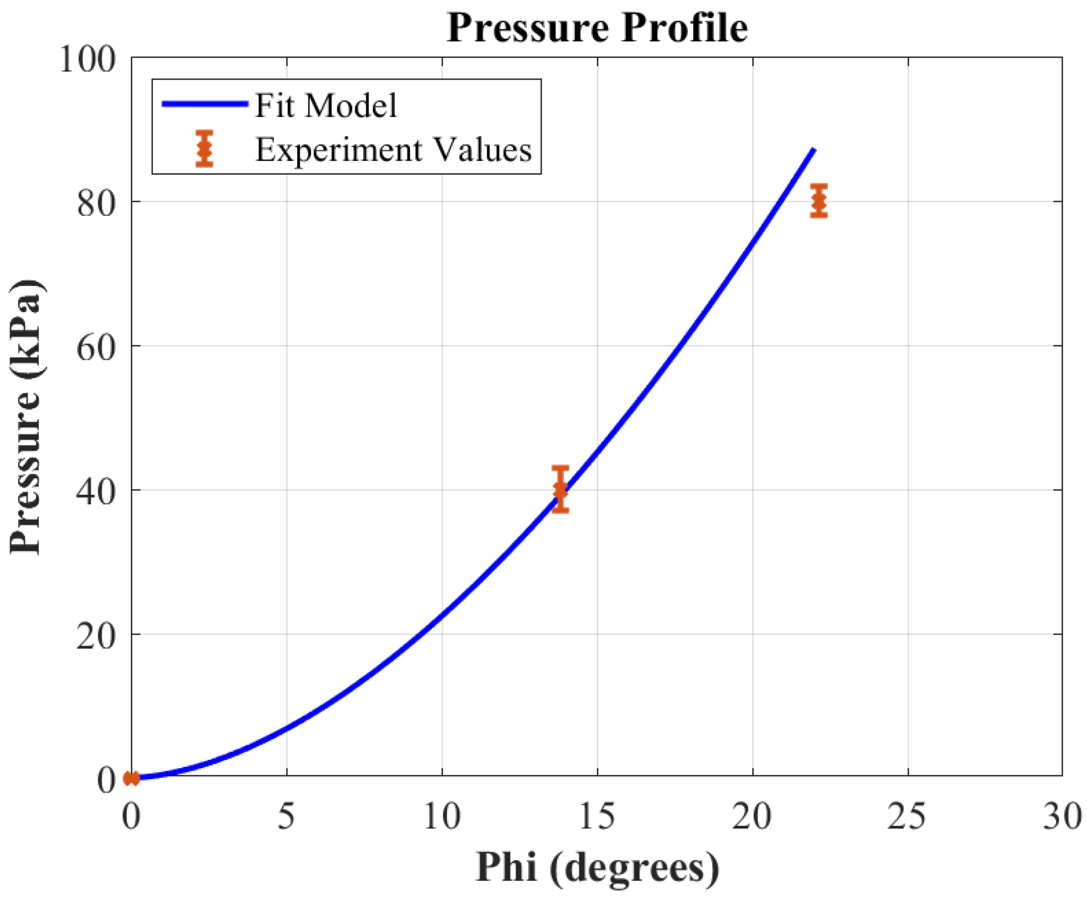
The kinematic relationship between the joint angle and the input pressure of the artificial muscles were studied and characterized in our previous work [55]. The experiments used for the kinematic characterization consisted of a two-link module fixed to a table at the rotating joint, and the two links were free to move. The input pressure was controlled using a gauge at the pressure source. The two-link module was actuated by turning the pressure gradually. The air in the actuated muscle was relieved to change the input pressure. The module at rest will return to a joint angle of ϕ = 0 due to the elastic behavior and antagonistic configuration of the muscles. For the kinematic characterization, the pressure input source was modulated in a certain range and the corresponding joint angle was measured. The experimental results for the relationship between the pressure and the joint angle including three data points in the desired actuation range was retrieved. An empirical model of the pressure that creates the desired joint angle, ϕ , presented in Equation (4), is obtained by curve fitting a power function to the experimental data (shown in Figure 2), as follows,
P = 0.4214 ϕ 1.7249 .
The power function was selected as the fitting curve function based on our insights from our previous extensive experimental studies [55,56]. Note that this model is applicable when the pressure is in kPa, and the desired ϕ is in degrees. The pressure range in this model was analyzed over a range of 0–75.8 kPa (i.e., 0–11 psi), which is the pressure range of the sensor (MPRLS Ported Pressure Sensor Breakout—0 to 25 psi, absolute pressure sensor Adafruit Industrial, New York, NY, USA) used in the control system.
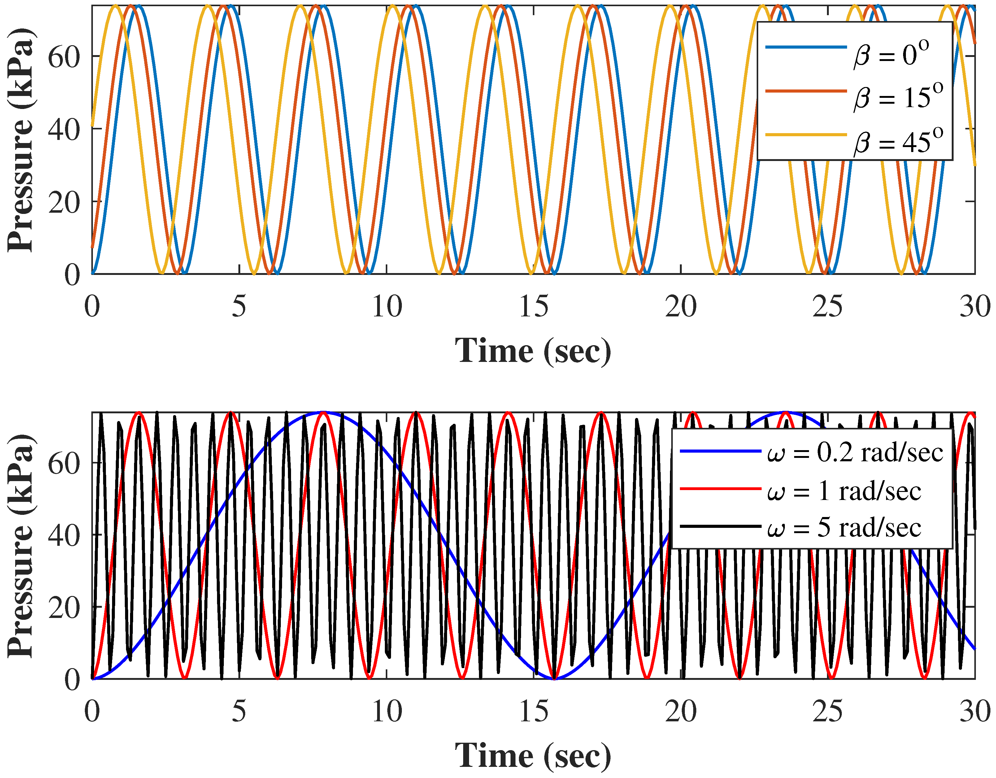
Now, by using Equations (4) and (6), we determined the variation of the required input pressure for generating the desired sinusoidal joint motion in the case of different β and ω . The values of α = 20 and γ = 0 were kept constant while three different values of β = 0 , β = 15 , β = 45 as well as three different values of ω = 0.2 rad/s, ω = 1 rad/s, and ω = 5 rad/s were used to simulate the required pressure for 30 s period of time, as shown in Figure 3. On one hand, the phase shift β between the adjacent joints of the snake robot is required to generate the lateral undulation, and the results show that the two adjacent muscle-driven joints need to be actuated with a delay of 0.3 s and 0.8 s for 15 and 45 phase shifts at ω = 1 rad/s, respectively. The delay time varies almost linearly with respect to the amount of the phase shift. On the other hand, the variation of ω reveals that to achieve different speeds by the muscle-driven snake robot, the frequency of reaching maximum pressure would be directly affected. This outcome provides insights into how fast the pneumatic control system (particularly, solenoid valves) must be open and close to provide the desired pressure pattern, as shown in Figure 3. Note the maximum pressure is 74 kPa for α = 20 which is in the range of the pressure sensor measurement.
To modulate the muscle-based snake robot’s joint angle, a PWM scheme was utilized to create the desired sinusoidal joint angle movement. This was achieved by turning a pneumatic valve between the pressure source and the artificial muscle on and off. The pressure inside the muscle gradually increases with each iteration. The joint angle decreases by relieving the pressure in the muscle by turning the relief valve attached between the muscle and the atmosphere on and off. The left and right muscles are actuated alternately between positive and negative joint angles. The right muscle is actuated when the desired ϕ is positive. This action is reversed when the desired ϕ is negative, as the left muscle is actuated while the right-side muscle is relieved of pressure.
The schematic in Figure 4 shows a unit of the electro-pneumatic circuit developed for each muscle to modulate the pressure within the artificial muscles on the robot. A pressure sensor is connected to an Arduino Mega logic board to read the internal pressure of each muscle. The pressure sensor is attached to the pneumatic tubing between the artificial muscle and the 3-way valve. The 3-way valve has 2 channel options. When the valve is ON, the channel creates a path from the input (pressure source) to the output (the artificial muscle). In turn, the ON state of the 3-way valve would supply air pressure to the muscle. When the valve is OFF, the channel makes a path from the output (the artificial muscle) to the exhaust, thus relieving the pressure from the artificial muscle to the atmosphere. A 2-way valve was attached to the exhaust of the 3-way valve to maintain the desired pressure in the muscle. This 2-way valve was closed in the OFF state. When the muscle pressure had to be decreased, the 2-way valve was turned ON and OFF to slowly relieve the pressure in the muscle until the desired pressure was met. A full electro-pneumatic control hardware was developed for a 6-link snake robot, as shown in Figure 5. The hardware includes an Arduino microcontroller (Arduino Mega 2560, Arduino, USA), I2C multiplexer (TCA9548A, Adafruit Industrial, New York, NY, USA), 3-way solenoid valves (X-Valve—Miniature Pneumatic Solenoid Valve Parker Hannifin, Cleveland, OH, USA), 2-way solenoid valves (6V Air Valve with 2-pin JST PH Connector—FA0520E, Adafruit Industrial, New York, NY, USA), and Driver Module (IRF520 MOSFET Driver Module, HiLetgo, Shenzhen, Guangdong, China).

2.3. Energy Efficiency

It is crucial to have a low-energy consumption system for robotic applications, especially those including robot locomotion in outdoor environments. To study the energy efficiency of the muscle-driven snake robot, the system is broken down into the following three elements:
  • Efficiency of a single pneumatic artificial muscle;
  • Efficiency of a single 2-link module;
  • Cost of transportation of the entire system.
For a single muscle case, the data from standard experiments used to characterize the dynamics of the artificial muscles were utilized [55], particularly the isotonic experiment where the length contraction is not constrained. Then, similar to the static studies done by Chou et al. [47] on pneumatic artificial McKibben muscles, the energy efficiency of individual artificial muscles was characterized. Next, a single 2-link module was studied by measuring the angular velocity and calculating the joint torque. Finally, the cost of transportation was selected as the metric to quantify the efficiency of the 6-link muscle-driven snake robot. The cost of transportation has been used in a wide range of applications to define the most energy-efficient mode of motion [58].

2.3.1. Energy Efficiency of Single Artificial Muscle

The energy consumption of an individual muscle was characterized. Pneumatic artificial muscles, or McKibben’s muscles, convert pneumatic energy into mechanical form by transferring the pressure from the inner surface of the bladder into shortening tension. A theoretical model made by Chou et al. [47] describes the input work ( W i n ) as
W i n = P Δ V
where P is the gauge pressure and ΔV is the volume change. The volume of the muscle can be approximated as a volume of a cylinder,
V = 1 4 π D 2 L .
The output work ( W o u t ) of a McKibben muscle is defined by the axial, F, tension, and the change in the length, Δ L [47].
W o u t = F Δ L .
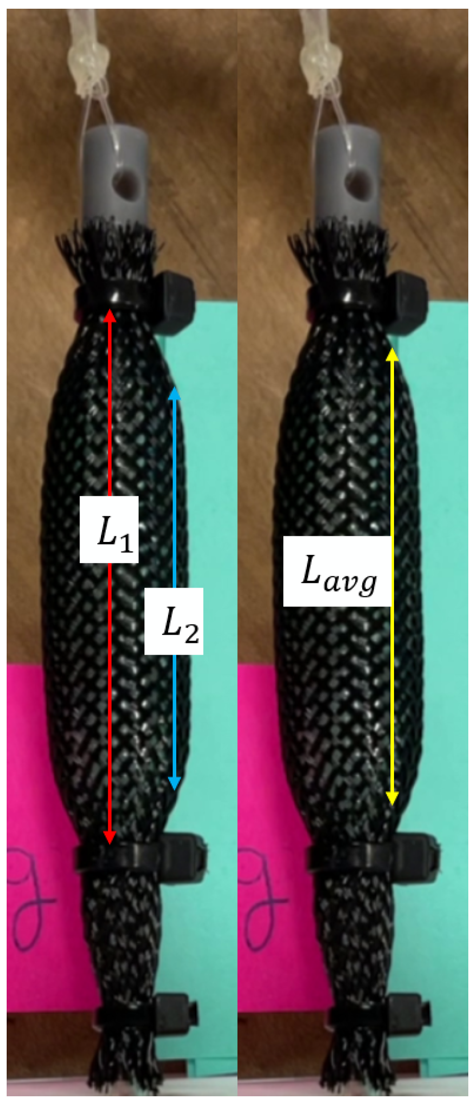
It was observed that the muscles were not perfect cylinders. After actuation, the muscles tapered at either end. Thus, a modified form of Equation (8) was used where L becomes L a v g , which is
L a v g = L 1 + L 2 2 ,
as shown in Figure 6.
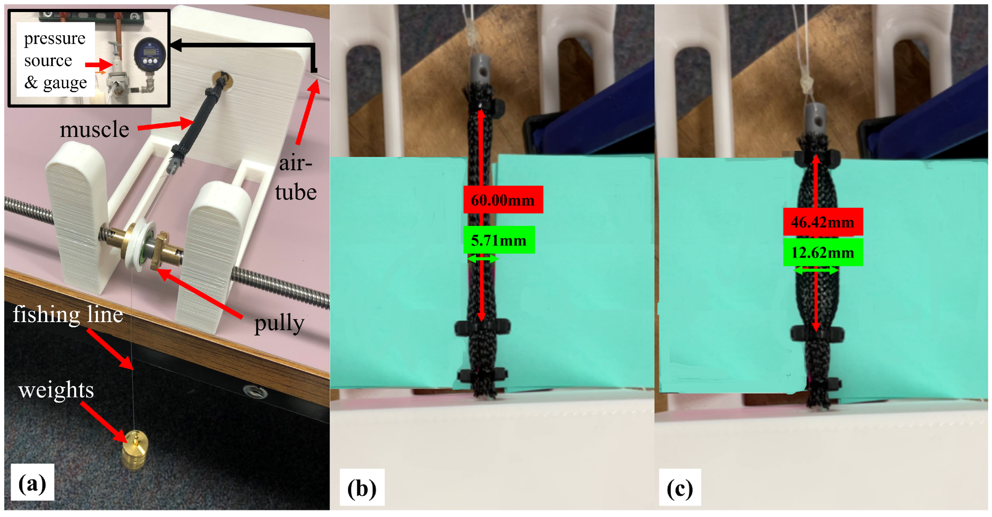
The isotonic concentric experimental setup in Ref. [55] was used to analyze the relationship between the muscle length variation and input pressure at varying applied forces; see Figure 7a. Weights were used to apply axial tension, F. The diameter, D, and change in length, Δ L , were retrieved using the video analytic and annotation tool Kinovea. The diameter and length of the resting muscle shown in Figure 7b were retrieved. The muscle was pressurized and after the contraction, the diameter and length were retrieved, as shown in Figure 7c.
The dimensionless energy efficiency, η , is defined as,
η = W o u t W i n ,
where the definitions of W i n and W o u t are given by Equations (7) and (9), respectively.

2.3.2. Energy Efficiency of a Single Muscle-Driven Module

A single module is defined, in regards to this article, as a two-link module that is capable of planar movement via joint actuation. The power consumption of a single module is defined by
W = τ ω ¯
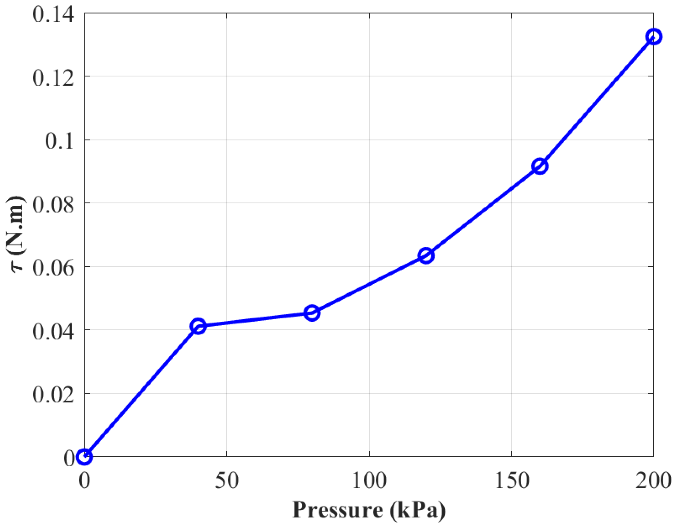
when W is the power consumption, τ is the moment of the muscle force about a given joint, and ω ¯ is the average of angular velocity ( ϕ ˙ ( t ) ) of the given joint. The relationship of the torque and change in pressure is shown in Figure 8. Moreover, the relationship of the average joint angular velocity and change in pressure is shown in Figure 9. From Figure 10, we can see the power consumption over the change in pressure. These values were found using Equation (11).

2.3.3. Energy Efficiency of 6-Link Mechanism

The propulsion of a snake robot is generated by the sinusoidal rotation pattern of the joints and the interaction of the rigid links with the ground with anisotropic friction. Kelasidi et al. characterized the energy consumption of underwater snakes [59]. The assumption is made that the joints are perfect, and thus the energy generated by the system is the sum of kinetic energy and energy dissipated by the system as follows,
E = E k i n e t i c + E d i s s i p a t e d .
Based on this concept, a model was proposed for the energy consumption of a snake robot with n links as follows,
E = 0 T i = 1 n 1 τ i ( t ) ϕ ˙ i ( t ) d t
where T is the time to travel a distance of 100 mm. The τ i is the actuation torque of joint i given by Equation (14) [55].
τ i = A τ i sin ( ϕ i ) + B τ i cos ( ϕ i ) F i
where A τ i and B τ i are the coefficients, which are a function of α i and d i and are defined as follows
A τ i = h 2 2 w 2 2 l w cos ( α i ) l 2 cos ( 2 α i ) 2 l h 2 sin ( α i ) d i
B τ i = l 2 sin ( 2 α i ) + 2 l w sin ( α i ) 2 l h 2 cos ( α i ) 2 w h 2 d i
and d i in Equations (15) and (16) is the theoretical length of ith muscle given by,
d i = A d i cos ( ϕ i ) + B d i sin ( ϕ i ) + C d i
A d i = 2 h 2 2 2 w 2 2 l 2 cos ( 2 α i ) 4 l w cos ( α i ) 4 h 2 l sin ( α i )
B d i = 4 h 2 w + 4 h 2 l cos ( α i ) 4 l w sin ( α i ) 2 l 2 sin ( 2 α i )
C d i = 2 h 2 2 + 2 l 2 + 2 w 2 + 4 l w cos ( α i ) 4 h 2 l sin ( α i )
and F i is the force generated by each muscle defined using the following empirical model [55];
F i = log ( L i ) + ( b d log ( P i ) ) a c log ( P i )
where a = 0.07 , b = 4.2 , c = 0.0113 , and d = 0.07 .
The torque at a given joint depends on four variables: the joint angle ( ϕ i ), the angle of the rotating attachment point ( α i ), the length of the muscle ( d i ), and the input pressure (P) of the artificial muscle. However, the ϕ i , α i , and d i are all a function of the input pressure of either the left or right muscle at a given joint. Therefore, the torque ( τ i ) directly relates to the input pressure. In order to generate the lateral undulation gait by the snake robot, the joints of the robot must follow Equation (4), which means that each joint follows a sinusoidal joint variation. The required actuation pressure over a given cycle is also sinusoidal. A 6-link muscle-driven snake was tested by moving over a 100 mm distance with an input angular velocity, ω , of 10 rad/s. The joint angle at each i link was measured and tracked using Kinovea (0.9.5) 2021 [60]. The pressure at a given ϕ i was found using Equation (6).

2.4. Power Consumption

The power consumption efficiency is calculated based on the following metric defined in other literature [1],
η = W T W R = i = 1 N m i g υ ¯ 1 T 0 T i = 1 N 1 τ ¯ i ω i d t
where W T is the total translational work required to carry the weight of the snake robot i = 1 N m i g with an average forward velocity of υ ¯ , and W R is the total input rotational work at the joints due to the average joint torque τ ¯ and joint angular velocity ω during a full locomotion cycle, of T. The current muscle-driven prototype has six links connected through five joints with a total mass of 0.27 kg, an average joint torque of 0.15 N.m [55], and an average joint angular velocity of 2.27 rad/s (130 /s). Thus, its power consumption efficiency, based on Equation (19), equals η = 1.56 υ ¯ . For a similar forward velocity υ ¯ in the range of 10–200 mm/s obtained by other snake robots, η varies between 0.016 and 0.32 for the muscle-driven snake robot, which is 1.5 times greater than the power consumption efficiency achieved by the Kulko snake robot reported in Ref. [1] with the same forward velocity.

3. Results and Discussion

3.1. Design Optimization

Table 1 shows the results of the optimization study. The actual design parameters closely follow the optimized parameters, except for l. l is the length of the rotating attachment point of the muscles. The muscles were not attached directly to the rigid link because the expansion of the muscle width interferes with the joint variation.
To study the optimized design, the workspace of the joint variation is studied. The average contraction of the PAMs used for this design is 76 % . Applying that same contraction to the optimized model will achieve the theoretical joint variation of ϕ i = 45 . For comparison, if the same contraction of 76 % is applied to the current model, the joint variation is ϕ i = 34 .

3.2. Energy Efficiency

The energy efficiency of a single muscle at varying axial tensions and applied pressure was analyzed. The results are shown in Figure 11.
The trend shows that energy efficiency is directly related to the force magnitude and will increase when the applied force increases. Overall, the efficiency ranges from 1.3 to 31.3%, and for instance, for the force applied of 9.81 N, the energy efficiency is varied in a range from 12.4 to 24.9%. This result is comparable to other artificial muscles that range from 10 to 49%. These pneumatic artificial muscles have a higher efficiency range than biological muscles, which range from 20 to 25% [47,53,54].

3.3. Control Test Results

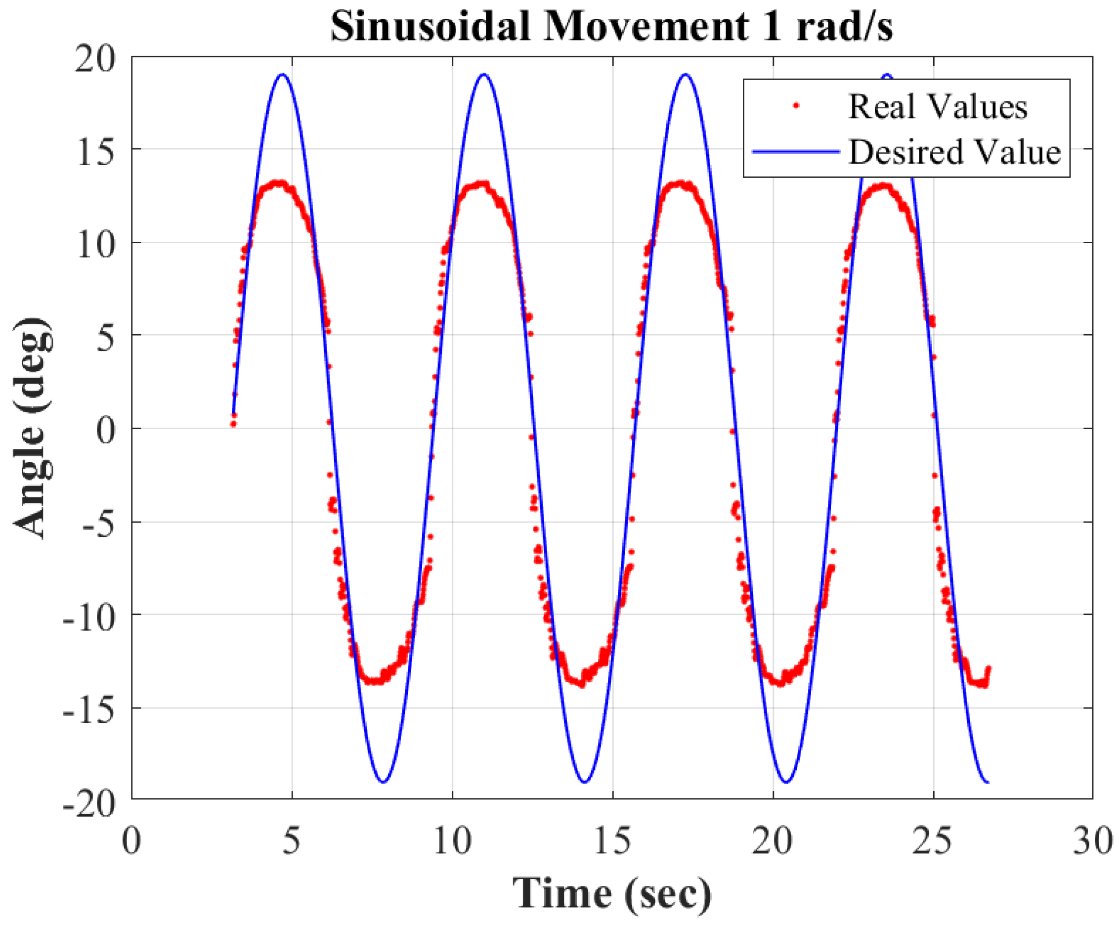
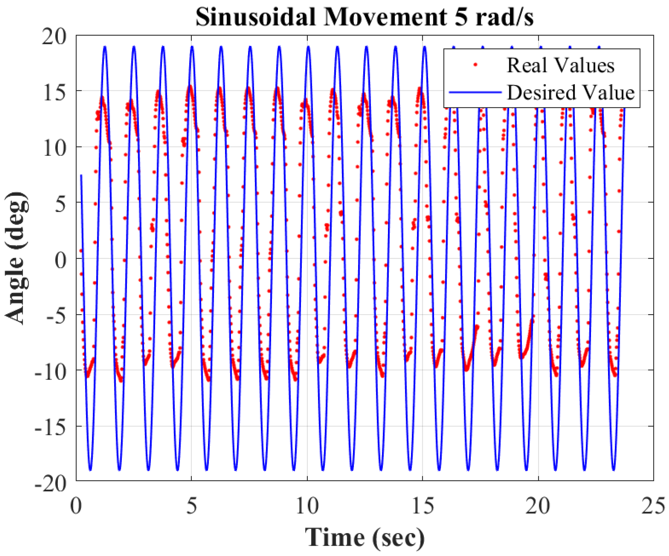
The sinusoidal movement was tested on a 2-link module. The module was fixed to the test table at the joint. A wave propagation frequency in Equation (4) of ω = 1 rad/s and ω = 5 rad/s was implemented on the 2-link module. As shown in Figure 12, the analytic and annotation tool Kinovea (0.9.5), 2021 [60], tracked the joint angle of the single module and recorded it every 0.017 s. The red dots in Figure 13 and Figure 14 indicate the recorded values against the desired values shown in the solid blue line. The desired values and output have a close trend. The output angle does not reach the desired amplitude due to a few factors. Most importantly, the muscle width interferes with the rigid link, thus preventing the total capacity of rotational movement. Moreover, the muscles also have manufacturing inconsistencies due to the artificial muscle being manufactured in our research laboratory.
The results of this test prove the feasibility of using pulse width modulation to create planar sinusoidal movement with a revolute joint actuated by artificial muscles.

3.4. The 6-Link Snake Robot Movement

The PWM control was extended to a 6-link model as shown in Figure 15. The desired ϕ i is given by Equation (4), and it was applied at each joint for a 6-link snake robot model. When the ω is increased, it is predicted that the forward velocity of the snake robot will also increase. The snake module was tested at ω ranging from 1 rad/s to 20 rad/s, as presented in Table 2.
The achieved velocities are slower than other snake robot models. This issue is due to a smaller joint motion range (0–19 degrees). The largest angle variation that this model can achieve is limited to the pressure range. The pressure sensor used in this work (Adafruit MPRLS Ported Pressure Sensor) has an absolute pressure range from 0 to 25 psi. With the ambient pressure on Earth being about 14.5 psi, the maximum gauge pressure is 10.5 psi. This pressure range will provide a joint angle of ± 19.75 .
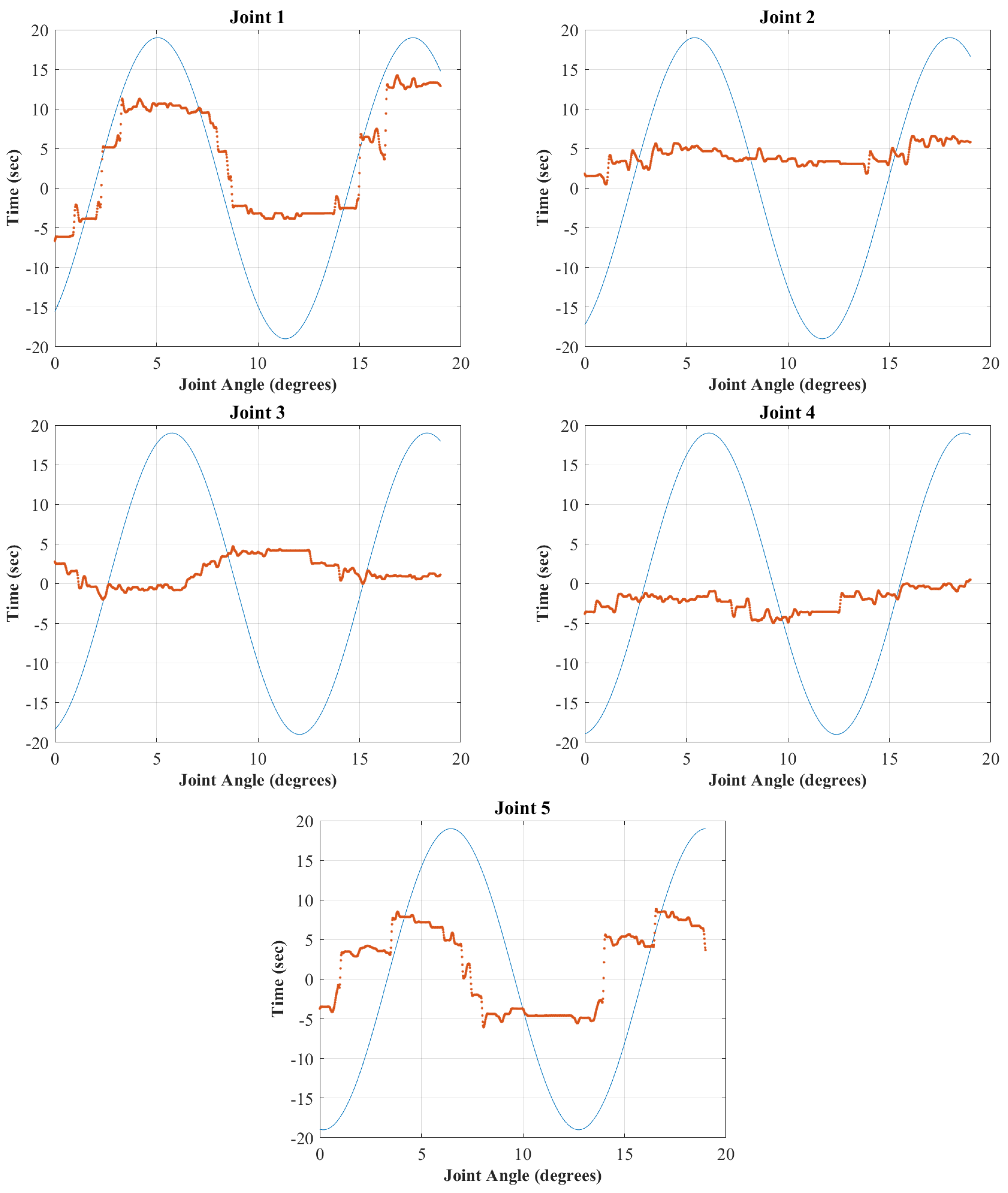
The 6-link snake robot was tested at the joint level for simple forward movement with a range of ω (in rad/s) including 0.5, 1.0. 2.0, and 10.0. The joint angles were annotated and recorded from the recorded video of the snake robot’s body movement. Figure 15 shows the annotated 6-link module with the joint angles. Figure 16 shows the actual joint variation (orange) and the desired joint angle variation (blue) with an input of ω = 10 rad/s. The results show that the revolute joints of the snake model could not match the desired frequency. This limitation can be due to the delay in the actuation of the muscles. The time it takes for the muscle to reach the desired pressure is not negligible. The muscle, in this instance, can be compared to a balloon filling up. By the time it takes for the muscle to reach the desired pressure, a few cycles of the desired joint angle have already passed. This results in a slower frequency than the desired ω = 10 rad/s. The i joint will hold the desired pressure while the i + 1 link will modulate to its desired pressure. The algorithm modulates joints in sequence and then repeats. Therefore, more joints mean a longer delay in the frequency of joint angle variation. To study this phenomenon further, we looked at the joint angle variation of ω = 2 rad/s (Figure 17). The desired and actual joint angle variation trend is closer to each other with a smaller ω . The test was repeated for ω = 1 rad/s and ω = 0.5 rad/s to determine the expected trend in the snake robot’s locomotion. Figure 18 and Figure 19 show the joint angle variation with an input of ω = 1 rad/s and ω = 0.5 rad/s, respectively. Considering all these joint variation results, we can conclude that a slower wave propagation velocity leads to better matching trajectory tracking. In addition, the results show that the first and the last joints are more capable of following the desired joint trajectory pattern in frequency and amplitude, while the three middle joints are less capable. This discrepancy can be related to the fact that the first and last joints of the snake robot are connected to a free link on one end while the other joints are coupling links that are coupled on their two ends. Thus, the motion of the muscles is interfered with by the contained movement of the connecting links as well as a lack of capability of the muscles to overcome the friction forces exerted onto each link.

3.5. Cost of Transportation

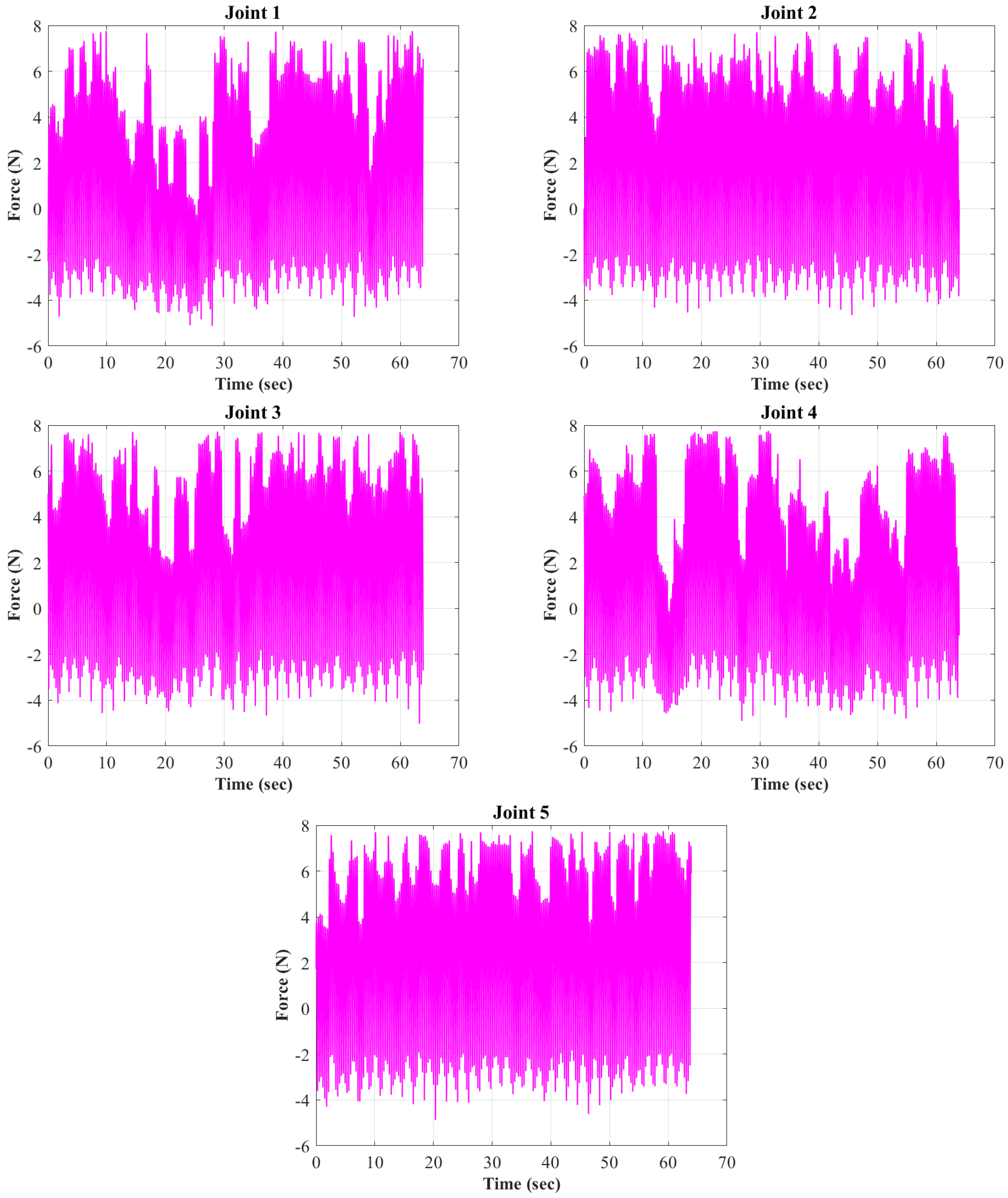
To determine the cost of transportation of our snake robot, a series of parameters including muscle lengths, muscle force, generated torque, and the power consumption are needed. The results of these parameters are shown in Appendix A. From the array of ϕ i , the d i , the length of muscles as shown in Figure A1, was approximated using the kinematic characterization model developed in Ref. [55]. For this case, the α i was set as a constant value of 3 . The force output of the muscles at each joint is depicted in Figure A2. The force was found using Equation (18). Moreover, the actuation torque ( τ i ) of joint i given by Equation (14). The actuation torque of a module tested with an input angular velocity ( ω ) at a given time is shown by Figure A3. The power is calculated by multiplying the torque, τ , with the joint angular velocities, ϕ ˙ , as shown in Figure A4, Appendix A. Finally, to find the cost of transportation, a MATLAB code was written and used to calculate the integral of the power based on the obtained values of τ and ϕ ˙ over the interval of time that it took the 6-link module to move 100 mm, which was about 64 s. The power efficiency is calculated based on Equation (19), which resulted in a transportation cost of 0.19. The reported range of transportation cost in Ref. [59] for other snake robots is from 0.01 to 0.75. The outcome indicates that our snake robot falls within a lower range of power efficiency compared to other snake robots. The lower efficiency is mainly due to a low velocity achieved by our robot due to the lack of capability by some of the joints (as opposed to proximal and distal joints) to follow the desired joint motion.

4. Conclusions

In this work, a series of studies on optimal locomotion and energy efficiency evaluation of the muscle-driven snake robot developed in our previous works [55,56,57] were carried out. Towards this goal, a kinematic-based design optimization was obtained for the snake robot to achieve an optimal range of joint motion. An electro-pneumatic control hardware was developed to control the robot’s locomotion and a control algorithm for generating lateral undulation gait. The energy efficiency of a single muscle (i.e., PAM), a single 2-link module of the robot, and a 6-link snake robot were also studied. Moreover, the power consumption was derived for the snake locomotion to determine the cost of transportation as the index for measuring the robot’s performance. Finally, the robot’s performance was analyzed and compared to similar models. The results, presented in Table 3, show the feasibility of using the muscle-driven mechanism for snake robot locomotion with comparable performance to other snake robots for the range of joint motion, power consumption efficiency, and Cost of Transportation. The validity of the muscle-based snake robot design was proven. For future work, the linear forward speed of the muscle-based snake robot can be optimized by considering the dynamics of the snake robot. Moreover, the low bandwidth issue of PAMs can be addressed by utilizing more precise and higher bandwidth solenoid valves or proportional valves, which can be adjusted continuously rather than the current solenoid valves’ discrete (digitized) operation.

Author Contributions

Conceptualization, M.L. and M.H.-J.; methodology, M.L. and M.H.-J.; software, M.L.; validation, M.L.; formal analysis, M.L.; investigation, M.L.; resources, M.H.-J.; data curation, M.L.; writing—original draft preparation, M.L.; writing—review and editing, M.H.-J.; visualization, M.L.; supervision, M.H.-J.; project administration, M.H.-J.; funding acquisition, M.H.-J. All authors have read and agreed to the published version of the manuscript.

Funding

This research was funded by the New Mexico Space Grant Consortium (NMSGC) and NASA EPSCoR Research Infrastructure Development (RID) fund under Grant No. 80NSSC22M0044.

Institutional Review Board Statement

Not applicable.

Informed Consent Statement

Not applicable.

Data Availability Statement

Access to the data will be provided upon request.

Acknowledgments

Marcela Lopez, the first author, was supported by New Mexico Space Grant Consortium (NMSGC) Graduate Research Fellowship while carrying out the project.

Conflicts of Interest

The authors declare no conflict of interest. The funders had no role in the design of the study; in the collection, analyses, or interpretation of data; in the writing of the manuscript; or in the decision to publish the results.

Abbreviations

The following abbreviations are used in this manuscript:
PAMPneumatic Artificial Muscle
COTCost of Transportation
3D3-Dimensions
psipound per squared inch
PWMPulse Width Modulation

Appendix A. The Length, Force, Torque, and Power Results of the Muscles
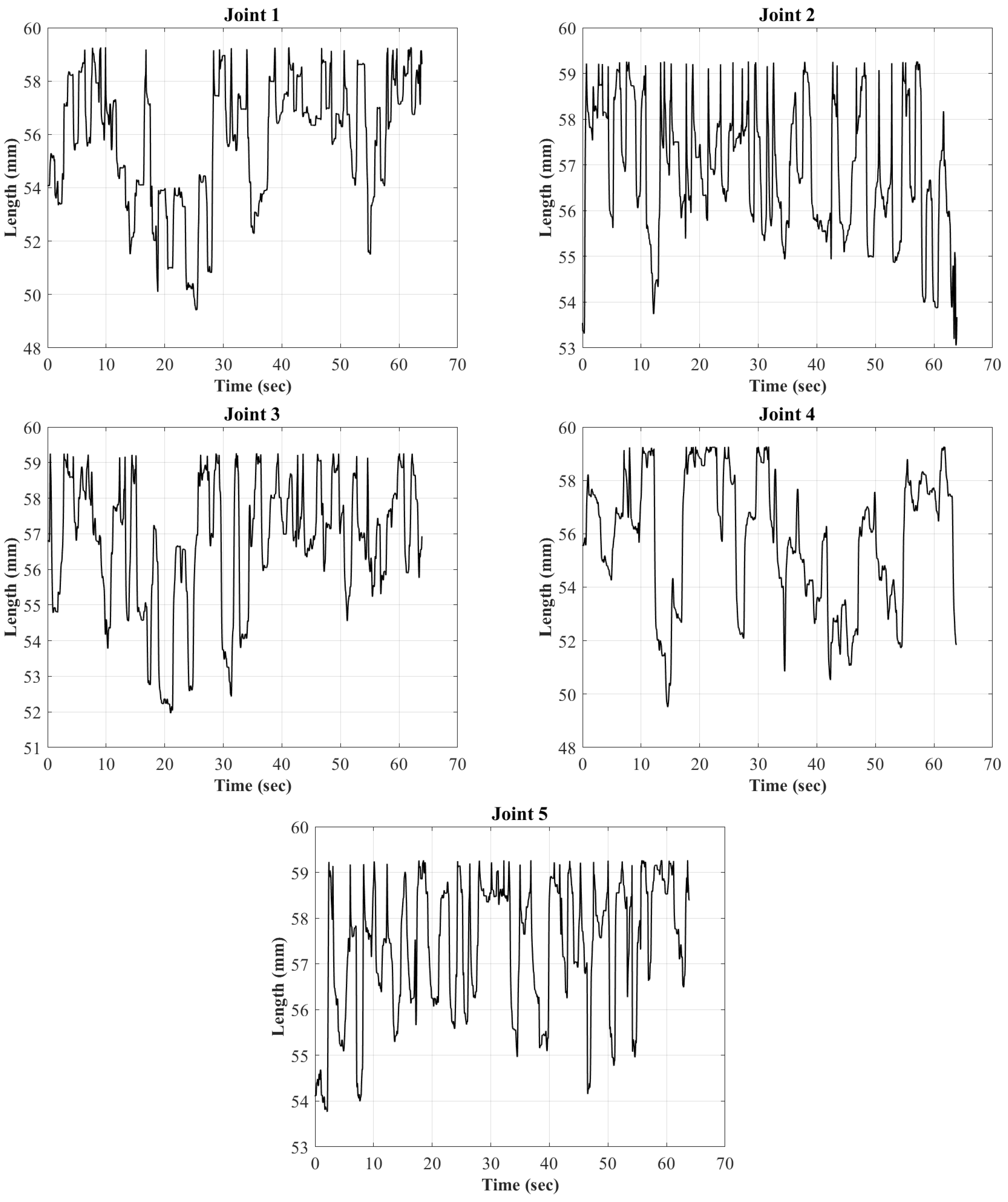
Figure A1. Time evolution of the length of the muscles at each joint.
Robotics 12 00089 g0a1
Figure A2. Time evolution of the force of the muscles at each joint.
Robotics 12 00089 g0a2
Figure A3. Time evolution of the generated torque by the muscles at each joint.
Robotics 12 00089 g0a3
Figure A4. Time evolution of the generated power (input power) by the muscle-driven mechanism at each joint.
Robotics 12 00089 g0a4

References

  1. Pettersen, K.Y. Snake robots. Annu. Rev. Control 2017, 44, 19–44. [Google Scholar] [CrossRef]
  2. Gray, J. The mechanism of locomotion in snakes. J. Exp. Biol. 1946, 23, 101–120. [Google Scholar] [CrossRef] [PubMed]
  3. Jayne, B.C. Muscular mechanisms of snake locomotion: An electromyographic study of the sidewinding and concertina modes of Crotalus cerastes, Nerodia fasciata and Elaphe obsoleta. J. Exp. Biol. 1988, 140, 1–33. [Google Scholar] [CrossRef] [PubMed]
  4. Jayne, B.C. Muscular mechanisms of snake locomotion: An electromyographic study of lateral undulation of the Florida banded water snake (Nerodia fasciata) and the yellow rat snake (Elaphe obsoleta). J. Morphol. 1988, 197, 159–181. [Google Scholar] [CrossRef]
  5. Hirose, S. Biologically Inspired Robots; Oxford Science Publications: Oxford, UK, 1993. [Google Scholar]
  6. Hirose, S.; Yamada, H. Snake-like robots [Tutorial]. IEEE Robot. Autom. Mag. 2009, 16, 88–98. [Google Scholar] [CrossRef]
  7. Dowling, K.J. Limbless Locomotion; Carnegie Mellon University: Pittsburgh, PA, USA, 1997. [Google Scholar]
  8. Rezapour, E.; Pettersen, K.Y.; Liljeback, P.; Gravdahl, J.T.; Kelasidi, E. Path following control of planar snake robots using virtual holonomic constraints: Theory and experiments. Robot. Biomim. 2014, 1, 3. [Google Scholar] [CrossRef] [Green Version]
  9. Liljebäck, P.; Pettersen, K.Y.; Stavdahl, O.; Gravdahl, J.T. Experimental Investigation of Obstacle-Aided Locomotion with a Snake Robot. IEEE Trans. Robot. 2011, 27, 792–800. [Google Scholar] [CrossRef] [Green Version]
  10. Rollinson, D.; Bilgen, Y.; Brown, B.; Enner, F.; Ford, S.; Layton, C.; Rembisz, J.; Schwerin, M.; Willig, A.; Velagapudi, P.; et al. Design and architecture of a series elastic snake robot. In Proceedings of the 2014 IEEE/RSJ International Conference on Intelligent Robots and Systems, Chicago, IL, USA, 14–18 September 2014; pp. 4630–4636. [Google Scholar] [CrossRef]
  11. Borenstein, J.; Hansen, M.; Borrell, A. The OmniTread OT4 serpentine robot—Design and performance. J. Field Robot. 2007, 24, 601–621. [Google Scholar] [CrossRef] [Green Version]
  12. Kota, S. Compliant systems using monolithic mechanisms. Smart Mater. Bull. 2001, 2001, 7–10. [Google Scholar] [CrossRef]
  13. Tolley, M.T.; Shepherd, R.F.; Galloway, K.C.; Wood, R.J.; Whitesides, G.M. A resilient, untethered soft robot. Soft Robot. 2014, 1, 213–223. [Google Scholar] [CrossRef] [Green Version]
  14. Marchese, A.D.; Onal, C.D.; Rus, D. Autonomous soft robotic fish capable of escape maneuvers using fluidic elastomer actuators. Soft Robot. 2014, 1, 75–87. [Google Scholar] [CrossRef] [PubMed] [Green Version]
  15. Sun, Y.; Zong, C.; Pancheri, F.; Chen, T.; Lueth, T.C. Design of topology optimized compliant legs for bio-inspired quadruped robots. Sci. Rep. 2023, 13, 4875. [Google Scholar] [CrossRef] [PubMed]
  16. Onal, C.D.; Rus, D. Autonomous undulatory serpentine locomotion utilizing body dynamics of a fluidic soft robot. Bioinspir. Biomim. 2013, 8, 026003. [Google Scholar] [CrossRef]
  17. Luo, M.; Agheli, M.; Onal, C.D. Theoretical modeling and experimental analysis of a pressure-operated soft robotic snake. Soft Robot. 2014, 1, 136–146. [Google Scholar] [CrossRef]
  18. Luo, M.; Pan, Y.; Skorina, E.H.; Tao, W.; Chen, F.; Ozel, S.; Onal, C.D. Slithering towards autonomy: A self-contained soft robotic snake platform with integrated curvature sensing. Bioinspir. Biomim. 2015, 10, 055001. [Google Scholar] [CrossRef] [PubMed]
  19. Branyan, C.; Fleming, C.; Remaley, J.; Kothari, A.; Tumer, K.; Hatton, R.L.; Mengüç, Y. Soft snake robots: Mechanical design and geometric gait implementation. In Proceedings of the 2017 IEEE International Conference on Robotics and Biomimetics (ROBIO), Macau, China, 5–8 December 2017; pp. 282–289. [Google Scholar] [CrossRef]
  20. Branyan, C.; Menğüç, Y. Soft Snake Robots: Investigating the Effects of Gait Parameters on Locomotion in Complex Terrains. In Proceedings of the 2018 IEEE/RSJ International Conference on Intelligent Robots and Systems (IROS), Madrid, Spain, 1–5 October 2018; pp. 1–9. [Google Scholar]
  21. Luo, M.; Wan, Z.; Sun, Y.; Skorina, E.H.; Tao, W.; Chen, F.; Gopalka, L.; Yang, H.; Onal, C.D. Motion Planning and Iterative Learning Control of a Modular Soft Robotic Snake. Front. Robot. AI 2020, 7, 599242. [Google Scholar] [CrossRef] [PubMed]
  22. Arachchige, D.D.; Perera, D.M.; Mallikarachchi, S.; Kanj, I.; Chen, Y.; Gilbert, H.B.; Godage, I.S. Dynamic Modeling and Validation of Soft Robotic Snake Locomotion. arXiv 2023, arXiv:2303.02291. [Google Scholar]
  23. Arachchige, D.D.; Perera, D.M.; Mallikarachchi, S.; Kanj, I.; Chen, Y.; Godage, I.S. Wheelless Soft Robotic Snake Locomotion: Study on Sidewinding and Helical Rolling Gaits. arXiv 2023, arXiv:2303.02285. [Google Scholar]
  24. Godage, I.S. Swimming locomotion of Soft Robotic Snakes. arXiv 2019, arXiv:1908.05250. [Google Scholar]
  25. Ma, S. Analysis of snake movement forms for realization of snake-like robots. In Proceedings of the 1999 IEEE International Conference on Robotics and Automation (Cat. No. 99CH36288C), Detroit, MI, USA, 10–15 May 1999; Volume 4, pp. 3007–3013. [Google Scholar]
  26. Guo, Z.; Mahadevan, L. Limbless undulatory propulsion on land. Proc. Natl. Acad. Sci. USA 2008, 105, 3179–3184. [Google Scholar] [CrossRef] [Green Version]
  27. Zhang, X.; Chan, F.K.; Parthasarathy, T.; Gazzola, M. Modeling and simulation of complex dynamic musculoskeletal architectures. Nat. Commun. 2019, 10, 4825. [Google Scholar] [CrossRef] [Green Version]
  28. Zhang, X.; Naughton, N.; Parthasarathy, T.; Gazzola, M. Friction modulation in limbless, three-dimensional gaits and heterogeneous terrains. Nat. Commun. 2021, 12, 6076. [Google Scholar] [CrossRef] [PubMed]
  29. Geijtenbeek, T.; van de Panne, M.; van der Stappen, A.F. Flexible Muscle-Based Locomotion for Bipedal Creatures. ACM Trans. Graph. 2013, 32, 1–11. [Google Scholar] [CrossRef]
  30. Wang, J.M.; Hamner, S.R.; Delp, S.L.; Koltun, V. Optimizing Locomotion Controllers Using Biologically-Based Actuators and Objectives. ACM Trans. Graph. 2012, 31, 1–11. [Google Scholar] [CrossRef]
  31. Cruz Ruiz, A.; Pontonnier, C.; Pronost, N.; Dumont, G. Muscle-Based Control for Character Animation. Comput. Graph. Forum 2017, 36, 122–147. [Google Scholar] [CrossRef] [Green Version]
  32. Rezaei, S.M.; Barazandeh, F.; Haidarzadeh, M.S.; Sadat, S.M. The effect of snake muscular system on actuators’ torque. J. Intell. Robot. Syst. 2010, 59, 299–318. [Google Scholar] [CrossRef]
  33. Gupta, A. Lateral Undulation of a Snake-Like Robot; Massachusetts Institute of Technology: Cambridge, MA, USA, 2007. [Google Scholar]
  34. Bruce, J. What Defines Different Modes of Snake Locomotion? Integr. Comp. Biol. 2020, 60, 156–170. [Google Scholar] [CrossRef]
  35. Moon, B.R.; Gans, C. Kinematics, muscular activity and propulsion in gopher snakes. J. Exp. Biol. 1998, 201, 2669–2684. [Google Scholar] [CrossRef] [PubMed]
  36. Davis, S.; Tsagarakis, N.; Canderle, J.; Caldwell, D. Enhanced Modelling and Performance in Braided Pneumatic Muscle. Int. J. Robot. Res. 2003, 22, 213–217. [Google Scholar] [CrossRef]
  37. Jozsef, S.; Gabor, S.; Janos, G. Investigation and Application of Pneumatic Artificial Muscles. Biomech 2010, 3, 208–214. [Google Scholar] [CrossRef]
  38. Zhang, S.J. Robotic Artificial Muscles: Current Progress and Future Perspectives. IEEE Trans. Robot. 2019, 35, 761–781. [Google Scholar] [CrossRef]
  39. Schroder, J.; Erol, D.; Kawamura, K.; Dillman, R. Dynamic pneumatic actuator model for a model-based torque controller. In Proceedings of the 2003 IEEE International Symposium on Computational Intelligence in Robotics and Automation. Computational Intelligence in Robotics and Automation for the New Millennium (Cat. No. 03EX694), Kobe, Japan, 16–20 July 2003; Volume 1, pp. 342–347. [Google Scholar]
  40. Tondu, B.; Lopez, P. Modeling and control of McKibben artificial muscle robot actuators. IEEE Control Syst. Mag. 2000, 20, 15–38. [Google Scholar]
  41. Kothera, C.S.; Jangid, M.; Sirohi, J.; Wereley, N.M. Experimental characterization and static modeling of McKibben actuators. In Proceedings of the ASME International Mechanical Engineering Congress and Exposition, Chicago, IL, USA, 5–10 November 2006; Volume 47659, pp. 357–367. [Google Scholar]
  42. Arcus, A.G. Modeling of a Dynamic McKibben Style Muscle System Using Material Properties. Master’s Thesis, Rochester Institute of Technology, Rochester, NY, USA, 2018. [Google Scholar]
  43. Balasubramanian, S.; Wei, R.; Perez, M.; Shepard, B.; Koeneman, E.; Koeneman, J.; He, J. RUPERT: An exoskeleton robot for assisting rehabilitation of arm functions. In Proceedings of the 2008 Virtual Rehabilitation, Reno, NV, USA, 8–12 March 2008; pp. 163–167. [Google Scholar]
  44. Kobayashi, H.; Hiramatsu, K. Development of muscle suit for upper limb. In Proceedings of the IEEE International Conference on Robotics and Automation, 2004. Proceedings. ICRA’04. 2004, New Orleans, LA, USA, 26 April–1 May 2004; Volume 3, pp. 2480–2485. [Google Scholar]
  45. Koeneman, E.; Schultz, R.; Wolf, S.; Herring, D.; Koeneman, J. A pneumatic muscle hand therapy device. In Proceedings of the The 26th Annual International Conference of the IEEE Engineering in Medicine and Biology Society, San Francisco, CA, USA, 1–5 September 2004; Volume 1, pp. 2711–2713. [Google Scholar]
  46. Wongsiri, S.; Laksanacharoen, S. Design and construction of an artificial limb driven by artificial muscles for amputees. In Proceedings of the International Conference on Energy and the Environment, Berlin, Germany, 9–12 September 2003; pp. 11–12. [Google Scholar]
  47. Chou, C.P.; Hannaford, B. Measurement and modeling of McKibben pneumatic artificial muscles. IEEE Trans. Robot. Autom. 1996, 12, 90–102. [Google Scholar] [CrossRef] [Green Version]
  48. Inoue, H. Whither Robotics: Key Issues, Approaches and Applications. In Proceedings of the IEEE/RSJ International Conference on Intelligent Robots and Systems. IROS’96, Osaka, Japan, 4–8 November 1996. [Google Scholar]
  49. Granosik, G.; Borenstein, J. Integrated joint actuator for serpentine robots. IEEE/ASME Trans. Mechatron. 2005, 10, 473–481. [Google Scholar] [CrossRef]
  50. Wang, T.; Wang, Z.; Wu, G.; Lei, L.; Zhao, B.; Zhang, P.; Shang, P. Design and analysis of a snake-like surgical robot with continuum joints. In Proceedings of the 2020 5th International Conference on Advanced Robotics and Mechatronics (ICARM), Shenzhen, China, 18–21 December 2020; pp. 178–183. [Google Scholar]
  51. Kakogawa, A.; Jeon, S.; Ma, S. Stiffness design of a resonance-based planar snake robot with parallel elastic actuators. IEEE Robot. Autom. Lett. 2018, 3, 1284–1291. [Google Scholar] [CrossRef]
  52. Ute, J.; Ono, K. Fast and efficient locomotion of a snake robot based on self-excitation principle. In Proceedings of the 7th International Workshop on Advanced Motion Control. Proceedings (Cat. No. 02TH8623), Maribor, Slovenia, 3–5 July 2002; pp. 532–539. [Google Scholar]
  53. Meller, M. Improving actuation efficiency through variable recruitment hydraulic McKibben muscles: Modeling, orderly recruitment control, and experiments. Bioinspir. Biomim. 2020, 11, 065004. [Google Scholar] [CrossRef]
  54. Robinson, R.; Kothera, C.; Wereley, N. Variable Recruitment Testing of Pneumatic Artificial Muscles for Robotic Manipulators. IEEE/ASME Trans. Mechatron. 2015, 20, 1642–1652. [Google Scholar] [CrossRef]
  55. Lopez, M.; Haghshenas-Jaryani, M. A Muscle-Driven Mechanism for Locomotion of Snake-Robots. Automation 2022, 3, 1–26. [Google Scholar] [CrossRef]
  56. Lopez, M.; Haghshenas-Jaryani, M. A Muscle-driven Mechanism for Locomotion of Snake-Robots: Kinematics, Design, and Prototyping. In Proceedings of the 34th Florida Conference on Recent Advances in Robotics (FCRAR), Virtual, 13–14 May 2021. [Google Scholar]
  57. Haghshenas-Jaryani, M. Dynamics and Computed-Muscle-Force Control of a Planar Muscle-Driven Snake Robot. Actuators 2022, 11, 194. [Google Scholar] [CrossRef]
  58. Shi, W.; Stapersma, D.; Grimmelius, H.T. Comparison study on moving and transportation performance of transportation modes. Int. J. Energy Environ. 2008, 2, 179–190. [Google Scholar]
  59. Kelasidi, K.Y.P.E.; Gravdahl, J.T. Energy efficiency of underwater snake robot locomotion. In Proceedings of the 23rd Mediterranean Conference on Control and Automation (MED), Torremolinos, Spain, 16–19 June 2015. [Google Scholar]
  60. Charmant, J. Kinovea (0.9.5). 2021. Available online: https://www.kinovea.org/ (accessed on 18 June 2023).
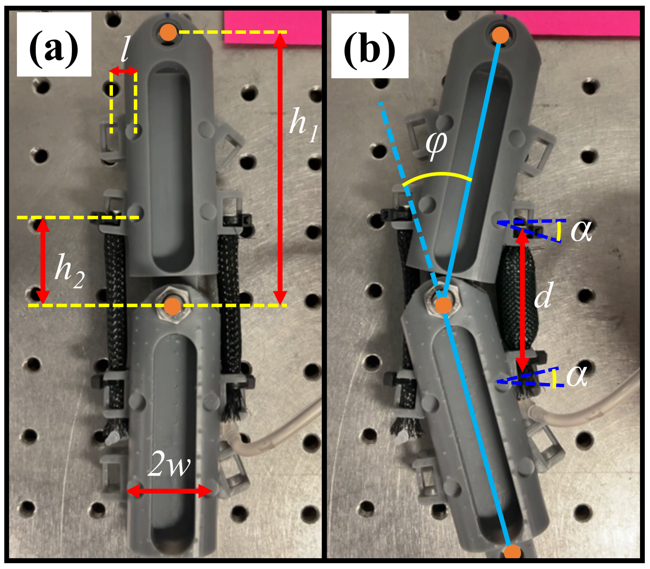
Figure 1. A muscle-driven snake robot kinematics and its geometrical features in the (a) inactive state and in the (b) right muscle activated state.
Robotics 12 00089 g001
Figure 2. Empirical law for the pressure profile fit to the experimental data.
Robotics 12 00089 g002
Figure 3. Time variation of the input pressure for the desired ϕ joint angle variation (top) at different β = 0 , β = 15 , β = 45 and (bottom) at ω = 0.2 rad/s, ω = 1 rad/s, and ω = 5 rad/s.
Robotics 12 00089 g003
Figure 4. Schematics of an electropneumatic control system diagram for a single muscle.
Robotics 12 00089 g004
Figure 5. Electro-pneumatic setup for a multiple link configuration.
Robotics 12 00089 g005
Figure 6. Adjusted muscle length.
Robotics 12 00089 g006
Figure 7. (a) Isotonic concentric experiment setup [55], (b) artificial muscle at rest and (c) actuated artificial muscle while carrying 1000 g mass at 200 kPa pressure.
Robotics 12 00089 g007
Figure 8. The relationship between torque and pressure in a single module.
Robotics 12 00089 g008
Figure 9. The relationship between average angular velocity and pressure in a single module.
Robotics 12 00089 g009
Figure 10. The relationship between power and pressure in a single module.
Robotics 12 00089 g010
Figure 11. Energy efficiency results of a single muscle.
Robotics 12 00089 g011
Figure 12. A single module of muscle-driven mechanism for the control test.
Robotics 12 00089 g012
Figure 13. PWM-based desired trajectory tracking control test at ω = 1 rad/s.
Robotics 12 00089 g013
Figure 14. PWM-based desired trajectory tracking control test at ω = 5 .
Robotics 12 00089 g014
Figure 15. The 6-link mechanism with annotations.
Robotics 12 00089 g015
Figure 16. Joint angle variation at each joint ( ω = 10 rad/s). The solid blue line is the desired values and the orange dots are the experimentally recorded data.
Robotics 12 00089 g016
Figure 17. Joint angle variation at each joint ( ω = 2 rad/s). The solid blue line is the desired values and the orange dots are the experimentally recorded data.
Robotics 12 00089 g017
Figure 18. Joint angle variation at each joint ( ω = 1 rad/s). The solid blue line is the desired values and the orange dots are the experimentally recorded data.
Robotics 12 00089 g018
Figure 19. Joint angle variation at each joint ( ω = 0.5 rad/s). The solid blue line is the desired values and the orange dots are the experimentally recorded data.
Robotics 12 00089 g019
Table 1. Kinematic-based optimization.
ParameterDefinitionOptimized ValueActual Value
h 2 (mm)The distance from the joint to the attachment point 28.8 30
d i (mm)The resting length of muscle 57.6 60
w (mm)The half width of each link 8.7 12
l (mm)The distance from w to muscle attachment point 3.7 7
α i The attachment point angle 0.24 No fixed value
Table 2. Achieved forward velocity at different ω .
ω Forward Velocity
20 rad/s1.2 mm/s
10 rad/s1.6 mm/s
2 rad/s0.83 mm/s
1 rad/s0.78 mm/s
Table 3. Muscle-driven snake robot comparative study.
Comparative VariablesMuscle-Driven Snake-RobotOther Snake Robots
Power Consumption Efficiency0.210.016–0.32 [1]
Cost of Transportation0.190.01–0.75 [59]
Range of Motion ± 30 ± 45  [1], ± 34  [51], ± 25  [49]
Disclaimer/Publisher’s Note: The statements, opinions and data contained in all publications are solely those of the individual author(s) and contributor(s) and not of MDPI and/or the editor(s). MDPI and/or the editor(s) disclaim responsibility for any injury to people or property resulting from any ideas, methods, instructions or products referred to in the content.