Article

Digital Twin as Industrial Robots Manipulation Validation Tool

1
Department of Mechanical and Industrial Engineering, Tallinn University of Technology, 19086 Tallinn, Estonia
2
National Institute of Standards and Technology, Gaithersburg, MD 20899, USA
*
Author to whom correspondence should be addressed.
Robotics 2022, 11(5), 113; https://doi.org/10.3390/robotics11050113
Submission received: 27 July 2022 / Revised: 2 October 2022 / Accepted: 13 October 2022 / Published: 18 October 2022
(This article belongs to the Special Issue Human Factors in Human–Robot Interaction)

Abstract

:
The adoption of Digital Twin (DT) solutions for industrial purposes is increasing among small- and medium-sized enterprises and is already being integrated into many large-scale companies. As there is an increasing need for faster production and shortening of the learning curve for new emerging technologies, Virtual Reality (VR) interfaces for enterprise manufacturing DTs seem to be a good solution. Furthermore, with the emergence of Industry 5.0 (I5.0) paradigm, human operators will be increasingly integrated in the systems interfaces though advanced interactions, pervasive sensors, real time tracking and data acquisition. This scenario is especially relevant in collaborative automated systems where the introduction of immersive VR interfaces based on production cell DTs might provide a solution for the integration of the human factors in the modern industrial scenarios. This study presents experimental results of the comparison between users controlling a physical industrial robot system via a traditional teach pendant and a DT leveraging a VR user interface. The study group involves forty subjects including experts in robotics and VR as well as non-experts. An analysis of the data gathered in both the real and the virtual use case scenario is provided. The collected information includes time for performing a task with an industrial robot, stress level evaluation, physical and mental effort, and the human subjects’ perceptions of the physical and simulated robots. Additionally, operator gazes were tracked in the VR environment. In this study, VR interfaces in the DT representation are exploited to gather user centered metrics and validate efficiency and safety standards for modern collaborative industrial systems in I5.0. The goal is to evaluate how the operators perceive and respond to the virtual robot and user interface while interacting with them and detect if any degradation of user experience and task efficiency exists compared to the real robot interfaces. Results demonstrate that the use of DT VR interfaces is comparable to traditional tech pendants for the given task and might be a valuable substitute of physical interfaces. Despite improving the overall task performance and considering the higher stress levels detected while using the DT VR interface, further studies are necessary to provide a clearer validation of both interfaces and user impact assessment methods.

1. Introduction

There is a growing body of literature recognizing the importance of digital twin (DT) in numerous research fields. An increase in the number of publications involving industrial human–robot interaction (HRI) and human–robot collaboration (HRC), in particular, demonstrates the focus of DT research in which virtual implementations of physical robot cells enable safe and efficient tools for system evaluation, training, and offline programming [1]. Despite the growing prevalence of DT in such applications, however, there is relatively little known about the human factors that drive and impact DTs of manufacturing systems [1]. Significant efforts continue to move toward human-centric design and implementation. Villani et al. [2], for example, present an extensive overview on HRC in industrial settings focusing on the main topics of safety, applications, and intuitive human–machine interfaces (HMI). That study presents alternative solutions to the traditional interfaces (i.e., based on keyboards and mouse, or teach pendants), namely walk-through programming, teach-by-demonstration methods, multimodal natural user interfaces (NUI; e.g., vision-based gesture recognition and audible speech recognition), and augmented, virtual or tangible user interfaces (TUI). That survey further points out the advantages of these innovative approaches in terms of reduction of time and costs related to the robot programming task and safety assessment, while also highlighting the importance of evaluating human factors such as stress, workload, and mental safety.
A number of practical reasons for pursuing DT solutions of manufacturing processes exist; and the number of challenges facing such implementations are plentiful. Technology transfer, retrofitting legacy robots, and adopting novel digital technologies in the historically manual and analog systems leveraged by small- and medium-sized enterprises are among the principal challenges [2]. Documenting the approaches and impacts of introducing DT in existing workcells is, therefore, expected to be both illuminating and beneficial in future iterations.
This study presents an application of DT in industrial robotic applications with a specific focus on the human factors that drive utility and adoption of DT technologies. A design of experiments is proposed to capture both quantitative and qualitative data regarding operator use and preferences of physical and virtual interfaces. A study involving forty ( N = 40 ) volunteers through Tallinn University of Technology is leveraged to evaluate and verify the test methodology and initiate a validation of the specific tools. The central hypothesis of the work is that the DT with enabled immersive technologies user interface can be adopted as a task/safety standards validation tool for Industrial robotic applications which involve human–robot interactions (HRI). The study aims at detecting if any degradation of user experience and task efficiency exists when using immersive user interfaces in comparison to real robot tech pendant. What we aim for is to introduce user impact evaluation within the DT VR interface prior to the actual adoption of the technology in real world use cases and at the same time find which are the most appropriate metrics to detect the efficiency and effectiveness of the proposed tools in respect to HRC tasks.

1.1. Related Studies

Several publications illustrate both the state of practice and emerging advancements in the field of DT augmented and virtual reality (AR/VR) interfaces for robot programming, training, and safety assessment. Nevertheless, not many works propose a standardization of evaluation methods for human factors and a ground base comparison of interaction efficiency between real and virtual environments able to define a set of metrics relevant and applicable to non use case specific scenarios. The horizon of studies, methods and tools in this respect is wide and heterogeneous. The following subsection attempts organizing them based on specific use cases and applications relevant for this study.

1.1.1. Input Modality Evaluation

The topic of NUI in HRI for industrial and service robots is discussed by Berg and Lu [3]. Their review mentions control interfaces based on gesture and speech recognition in combination with virtual and augmented reality, portable devices, or eye-tracking, highlighting the importance of a multimodal approach to HRC. The study by Krupke et al. [4] presents an experimental setup comparing mixed reality (MR) robot interaction and control based on heading position and direct selection, with speech input for task and action commitment. A virtual robot arm is used in a pick-and-place task, and is synchronized and superimposed over the display of a physical robot, allowing for movement preview in MR and facilitating the robot programming task and procedure. Experimental results confirm that heading-based selection of controls to be faster, more precise, and less demanding on the user. Their tests assess operator performance through commonly-used questionnaires, namely the National Aeronautics and Space Administration’s Task Load Index (NASA-TLX, [5]), the System Usability Scale (SUS, [6]), the AttrakDiff Usability Questionnaire [7], and objective metrics like completion time and accuracy. The study by Whitney et al. [8] compares 2D and DT based immersive VR interfaces aimed at robot control in a simple object stacking task. The evaluation of different control interfaces includes direct manipulation, keyboard and monitor, hand position tracking with monitor visualization, hand position tracking in combination with virtual reality. User tests, together with NASA-TLX and SUS responses, indicate that the VR interface is more efficient, faster, with a lower workload and higher usability than the monitor and keyboard one. Hand position tracking is also an important key advantage in robot manipulation in combination with both monitor based and VR visualization methods. Direct manipulation proves to be the best type of interface for the given task overall. A VR DT interface for aircraft engines performance control is presented by Tadeja et al. [9]. Information and nominal performance maps are synchronized with both real and digital representations of engines, allowing for real-time visualization and manipulation in the immersive environment. Several VR-based interfaces and interaction methods, such as pinch based hand manipulation and gaze tracking, are tested by a limited number of users in the performance of a specific engine inspection and control task using the proposed application. An extensive set of metrics and questionnaires are employed in this study to detect user health, workload and reactions to the virtual scenario, such as sickness and flow. Among the others the author mention the Simulation Sickness Questionnaire [10], Flow Short Scale [11], NASA-TLX and Igroup Presence Questionnaire [12]. The study by Laaki et al. [13] makes use of a virtual reality DT environment for the remote teleoperation of a Universal Robot UR3 robotic arm to simulate a remote surgery scenario. The study focuses on security, reliability of the connection over a mobile network and usability of the system. The importance of Quality of Experience (QoE) and the assessment of human factors, such as sense of presence, visual fatigue, cyber-sickness, and system acceptance in VR based teleoperation tasks is discussed by Concannon et al. [14]. The study presents a framework for QoE assessment by employing a DT simulation in VR and tries to establish the impact of network delay by using implicit and objective metrics. User physiological data such as heart rate, electrodermal activity, eye-tracking focus of attention and environment interaction variables are used as a base for user experience assessment.

1.1.2. Human Robot Collaboration and Work Cell Optimization

The literature is rife with examples of evaluations to demonstrate and assess DT in HRC applications. Matsas et al. [15] describe a VR HRC environment for the performance of complex tasks in a collaborative industrial use case. The VR scenario is enriched by audio-visual cues, cognitive aids, and interaction metaphors. The reported evaluation of the system gives positive results in term of acceptance. In particular, the users appreciated the system aids and cues, particularly when turning into potential danger and collisions warnings and alerts. Despite proposing several user experience evaluation metrics the study fails in providing a standardized assessment of user perception and experience in the system by utilizing a custom made questionnaire. Similarly, Oyekan et al. [16] explore the effectiveness of VR in developing HRC strategies. An experimental DT is employed in the evaluation of human reaction to unexpected robot movements while carrying out a human-fed, pick-up-and-transfer task. A variety of different metrics are considered, including head acceleration, head and neck energy metrics, direction and angle of human reaction and Head Injury Criteria-based force related danger of the robot movement. The study suggests that VR DT can help determining and understanding human reactions to robot movements facilitating the definition of HRC strategies in a safe and controlled environment. In this study, a custom questionnaire is employed to capture the users reactions to robot behaviours. Complimentary to this, DT is also leveraged as a tool for HRC task design and wok cell design optimization. An architecture for DT MR environment aimed training and based on a modular experimental collaborative robot assembly plant is described by Sievers et al. [17]. The study by Yap et al. [18] presents a VR projection-based environment for robot control and programming. Taking into account ergonomics parameters for each worker, the Virtual Wall hardware architecture includes head and hand-manipulator tracking, polarized glasses and filters, active stereo glasses with a non-polarized projection screen. The system aims at the design and optimization of the cell layout and, in a second phase, at the use of the validated setup in the robot programming task. Once validated the robot paths are transferred to the real robot for testing. The study by Malik et al. [19] describes a framework for a VR-based HRC process design. A DT of the robotic cell and a human avatar are employed for collision analysis, reach, vision and placement tests of the robotic cell modules and components. A virtual interface allows the user to interact with the environment and the robot end effector. The validated robot positions are saved for later use in the real world robotic cell and synchronized with the physical robot. The study in Pérez et al. [20] validates the layout design of a multi-robot industrial cell in VR making use of existing DT cell components. The experiments described in the study by Peruzzini et al. [21], attempt a holistic description and modeling of an operator involved in an industrial vehicle assembly task. The goal is to improve and optimize the assembly workspace and find corrective actions for possible emerging issues. This study constitutes an interesting example of assessment of the impact of the adopted technologies and evaluation methods on the user, and the validation of the design approach for the specific use case, being as well applicable to HRI scenarios. A large number of subjective and objective metrics are collected and analyzed during experimental sessions in the real scenario, in VR and in mixed reality. Bio sensors, motion capture, video recordings and eye tracking are involved in collecting information over heart rate, breath rate, temperature, eye gaze and pupil dilation, body position and movements. Both physiological and psychological response are employed in the assessment of mental workload, comfort, ergonomics parameters, posture, visibility, and occlusion. The occupational repetitive actions (OCRA, [22]) Index and RULA score are used together with heuristic analysis in the assessment of ergonomics of the workstation while NASA-TLX questionnaire is employed for subjective workload evaluation.

1.1.3. Ergonomics and Safety Evaluation

From a more safety and user-centric perspective, Harvard et al. [23] present a simulation and communication architecture intended to design and evaluate assembly lines, manufacturing processes, and workstations. The system employs a DT VR interface allowing for efficient and safe configuration and validation test of the workstation setup and ergonomics. The user based evaluation is, in this case, achieved by adopting a Perception Neuron Pro sensor-embedded suit, for body posture and skeleton detection, and leveraging the Rapid Upper Limb Assessment (RULA, [24]) ergonomics scoring tool. Likewise, an experimental comparison of robot collision prediction and control via direct supervision, monitor and mouse interface and a mixed reality system is presented by Rosen et al. in [25]. Experimental results show that the MR interface is significantly more efficient, direct, and easier than monitor visualization and control while not being significantly less efficient and usable than the direct supervision of the robot. The study makes use of the NASA-TLX and SUS to determine user workload and assess system usability for the three interaction methods. With respect to user training and safety assessment in a HRC industrial setting, Moniri et al. [26] propose a remote collaborative setup supported by eye-tracking and virtual reality. The system is meant for online remote tutoring, training, and assistance. The experimental setup encompasses two synchronized workstations, a real and a virtual one. The system can track the position of the objects involved in the task, the robot manipulator orientation, user head position, and eye movements. Focus of attention information for each user can be visualized by the remote assistant during the pick-and-move task. Object collision avoidance is discussed by Wassermann et al. [27]. The monitor-based augmented reality application allows for the visualization of bounding boxes around real objects involved in a pick-and-place task. The system can detect and visualize the collision of the virtual robot with the bounding boxes by changing their color in real-time. Several robot safety behaviors are tested by Vosniakos et al. [28] making use of the virtual environment presented by Matsas et al. [15]. The study explores the effectiveness of HRC collision avoidance methods such as speed reduction and move back strategy. Similarly, the work by Maragkos et al. [29] aims at developing a collision avoidance system based on slow down strategy and alternative movement path on a traditional industrial robot for safe HRC and programming. The system implements a VR DT of the real robot where the virtual space is mapped and subdivided in 3D regions which are subsequently checked for the presence of the human avatar. The experimental study presented by Manou et al. [30] adopts a virtual reality robotic cell twin for the assessment of collision detection and robot movement paths generated by manually operating a sensor-enabled teaching tool in a lead-through programming method session.

1.1.4. Robot Programming

Similarly, DT is often leveraged for programming robotic tasks. A virtual environment for training simulation and programming in proposed by Pérez et al. [31]. The operator can interact with the robot through a virtual interface and assess the efficiency and safety of the proposed robot trajectories. The system stores paths and trajectory information from the virtual robot for further data analysis, training, and real robot programming. A custom questionnaire is employed to assess users experience of the system. A mixed reality robot programming interface making use of HoloLens is presented by Ostanin and Klimchik [32]. A virtual robot is programmed by a set of AR interfaces, manipulators and tools controlled by gesture inputs (tap, tap and hold). The system is tested for object avoidance and the creation of linear, circular and rectangular task programming paths. The AR interfaces allow the operator to modify (erase and scale) the proposed paths and directly control the robot’s joints movements. The study in Nathaneal et al. [33], compares performance metrics over different user groups programming a robot by means of a traditional teach pendant, a non-immersive virtual environment and a virtual-augmented system. The user performance evaluation focuses on timing, the number of coordinate axis changes, and optimal piece positioning with the end effector. Several signals and alerts are implemented in the virtual environment to facilitate the robot programming task. Experimental results demonstrate that programming performance and time would benefit from the augmented cues and signals implemented in the system. The study suggests that the skills developed in the VR environment are transferred in the real case scenario by facilitating learning of traditional interfaces and robot manipulation. A lead-through offline programming approach based on augmented interfaces and a handheld pointer is presented by Ong et al. [34]. The pointer is directly operated by the user to create and modify paths related to different manufacturing tasks. Graphical cues real-time information about manipulability and reachability for each proposed path. The application is tested on a group of users confirming the usability of the system and a reduced amount of programming time compared to traditional methods. User experience and system usability are assessed based on a custom questionnaire and by comparing quantitative data collected during different experimental sessions. A VR based system for robot programming in a collaborative scenario is presented by Burghardt et al. [35]. Unfortunately, the study does not provide quantitative data analysis on the comparison of traditional programming methods and the proposed application.
Several publications propose an assessment and evaluation of the effectiveness of interaction methods and hardware for DT interfaces, but only a few try to compare traditional robot programming methods and immersive VR DT solutions. In this sense, it is important to determine whether there is a degradation in the use of DT VR interfaces compared to real robot teach pendants and establish if the former can be reliable and efficient substitute for HRI. Moreover, the evaluation of human factors and the impact of the system on users’ interaction with VR interfaces are not frequent and, in most of the cited cases, use case specific. Several aspects are determining the efficiency and effectiveness of VR interfaces for HRC including the acceptance of the system, usability, users’ stress level, and workload. By analyzing specific metrics in a real HRI and in a DT VR scenario, this study aims at the comparison of performances in robot programming using traditional and VR interfaces and the evaluation of their impact on the operator. We believe this type of assessment should be performed prior to use case specific applications, addressing the need for metrics and validation methods which would acknowledge the centrality of the operator in the DT loop as part of the VR interface and at the same time address the effectiveness of a DT system for robot control. To do so it is necessary to compare the control efficiency and user interactions with the interface in the virtual environment compared to the physical workspace and evaluate what is the impact of both on the operators. The hypothesis is that the DT VR tools can be as efficient as their real counterpart with minor impact on the user health, stress levels and performance indicators.

2. Methods

The experiments presented in this study consist of both physical and virtual tests in identical work cells as showed in Figure 1. Both the physical and virtual robot configurations were used to complete identical material handling tasks. The tasks consisted of moving three cubes–located in different parts of the workspace to a predefined target region. Each cube has a predefined starting position and must be picked up and moved to the target region in a specified order. The robot is teleoperated by the human subject using interfaces specific to the operating environment: experiments using the real robot were performed using the teach pendant provided by the robot’s manufacturers (see Figure 1), and experiments using the virtual robot leveraged a custom user interface displayed in the simulated environment (see [36], and Section 2.3.1 for the description of this interface.

2.1. Human-Robot Interaction Metrology

Several different metrics and test methods for assessing and assuring HRI technology performance are detailed in the literature (e.g., [37]). This broad spectrum of metrology tools can make selecting appropriate test methods a significant challenge. Given this study’s focus on the use of VR for HRI, a collection of metrics that capture interface utility and operator reactions to the interface controls are warranted.
To capture the human operator’ interactions with the interface, a combination of quantitative and qualitative metrics (both objective and subjective) are selected. The objective measures capture the nuances of user interaction with the interface that may not be registered or recollected by the operator in a post-test questionnaire assessment. In contrast, the subjective measures capture the in situ effects of interface interaction and manipulation for a specific individual at a particular time during or after the test. Given that external and personal factors (e.g., the effects of weather, diet, and recent events on the individual’s temperament and focus) are often influencing subjective results, it is generally advisable to consider them as anecdotal samples of a larger range of random responses rather than an absolute constant. Therefore, the trends of these responses are more indicative than the responses themselves.
The objectively quantifiable measures selected are intended to capture how the operators actually use the interface. In particular, the measures identify three important factors: (1) how much time was required to complete the task, (2) where the operator’s focus is predominantly drawn to throughout the task, and (3) how much time is spent focusing on these elements. To achieve this, the following factors are captured and reported in this report:
  • the average time to complete the task working with the physical robot versus working in the virtual environment;
  • the average total duration of the experiments using the VR interface including both the time to complete the task and the time to adjust to the virtual environment;
  • the average duration using or focusing on the different virtual interface commands (e.g., adjusting joint speeds/positions or changing operational modes);
  • the average total time spent looking at the elements of the VR interface, the time spent looking at the virtual robot, and the time spent doing something else (e.g., doing some other task work not directly related to the robot).
Only the first of these metrics is captured for both the physical and virtual robot work cells. No reliable and repeatable system currently exists for tracking operator attention or gaze focus for real-world interfaces. In contrast, operator eye motions can be reliably tracked in the virtual environment using VR headset-mounted eye trackers. As such, the sampling of objectively quantitative measures can be built directly into the interface itself.
Two subjectively quantifiable measures were selected to capture the users’ experiences of using the interfaces. It has been seen that exposure to and experience with robots has an impact on the users’ responses to robots. For example, if the operator has plenty of exposure to robots (e.g., as an influence of popular culture representations such as in movies) but little practical experience working with them, these users may over-estimate the robots’ intelligence and capabilities. Similarly, users who have both little exposure and little experience with robots may express fear or excitement working with the robots. To this end, the following metrics were captured:
  • the demographics of the human operators, including age, gender, and nationality;
  • the operators’ previous experience with working with both robots.
Finally, two popular, subjectively qualitative survey tools are selected to probe the operators’ reactions and opinions of working with the robots in both the physical and virtual work spaces. These surveys are intended to capture the operators’ perspectives on the difficulty of using a given interface, and the operators’ perspectives on how they felt around the robots:
  • the NASA-TLX captures the operator’s mental and physical effort required to complete a task;
  • the Godspeed questionnaire [38] records the operators’ perspectives of the anthropomorphism, animacy (i.e., how lifelike something appears), likeability, perceived intelligence, and safety of the real and virtual robot systems.
It is worth noting that additional subjective software quality metrics and test methods have been standardized in ISO 25010 (“Systems and software engineering-Systems and software quality requirements and evaluation (SQuaRE)-System and software quality models,” [39]). However, these test methods and metrics capture only the user’s perspective on the quality of the software (i.e., the interface), and does not reflect the user’s experience using the software for interacting with robots.

2.2. Data Collection: Integrating Metrics

Each element that can be manipulated (i.e., buttons and sliders) on the VR interface canvas is assigned a unique tracking identifier. Each UI function controlled by the operator has an attached script that identifies with which feature the user is currently interacting, as well as the type of ongoing interaction (e.g., button press/release). The operator’s direction of gaze is estimated by casting a virtual line, originating from the normal surface of the head-mounted display (HMD), extending outward to the virtual world. During the experimental session, such setup allows to record any user’s interactions with the UI in a timeline, which is then saved to a JavaScript Object Notation (JSON) file detailing all events on a per-element basis.
A script simulating network instability and lag was also introduced for the virtual robot. This script injects arbitrary disturbances into the visual representation of the DT, with the goal of affecting the operators’ behavior. The generated experimental session file can be later used to analyze the performance of each operator. For example, an activity heatmap can be generated on top of the UI image to visualize the length of time spent in each UI section, or the amount of interactions with each unique element.
Both the NASA-TLX and the Godspeed metrics are post-task surveys, so do not provide real-time data collection. The inputs from these surveys are then assessed in an effort to map the operators’ responses to their respective interactions with the interface.

2.3. Technical Implementation

To evaluate the differences between the experience of the operators when working with the real robot system and its digital counterpart, an existing DT system was augmented with tools to track behavior metrics of the users, as described in Section 2.2. Several tracking metrics were used when collecting data during the experimental sessions. These include timing, and the operators’ attention and stress levels. A detailed description of the experimental configuration is described presently.

2.3.1. The Digital Twin System

The DT system used as a basis for this experiment was developed at the TalTech Industrial Virtual and Augmented Reality Laboratory (IVAR) during the previous research on the relevant topic (see [36,40,41]). The system was developed using the Unity game engine, and contains a digital model of an industrial robot that can be manipulated using the accompanying UI located in virtual environment (see Figure 2).
The model of the robot is retrieved from the manufacturer’s website, and went through an optimization procedure including rigging and the creation of rotation axes, mesh simplification, and scale correction. These last steps are necessary to ensure that the imported mesh would be identical to the objects in the real scenario. Hierarchical structures between rig pivots (robot axes) is maintained and based on the original robot technical drawings. Precision of joint controls in the virtual environment is identical to the real robot precision with accuracy of 0.001 degrees, and joint limits are set to be identical to the real counterpart. The speed of the synchronized real robot is proportional to the one set by default in the DT VR environment. Although the physical robot has built-in collision detection (which was triggered several times throughout the experiments), no collision avoidance scripts were used in the DT counterpart.
The DT can be operated in “coupled” and “virtual” modes. In the coupled mode, all commands are duplicated and sent to the physical robot over the local network, effectively keeping the virtual robot synchronized with its real-world counterpart. In the virtual mode, the network link between the DT and the real robot is disconnected. All actions happen inside the simulation only. Apart from these connection modes, the UI provides two control mechanisms for commanding robot motions. The user can either directly tele-operate the robot arm by adjusting individual joint positions, or create a multi-step, joint-space program to be stored and executed later.
For this experiment, the virtual mode with direct control was chosen for two reasons. First, the DT operated in virtual mode is not bound to the physical speed and safety limits set in the real robot system, which allows an unbiased assessment of the possible performance benefit of DT solutions. Second, controlling the virtual robot directly is similar to controlling the real robot with its included teach pendant, and does not introduce additional complexity in the form of creating and executing program. This was particularly important, as the collection of human operators participating in the experiment represented a wide spectrum of prior experiences and expertise with robot systems. Using direct control eliminates unnecessary complexity when preparing for the experimental session.

2.3.2. Attention Tracking System

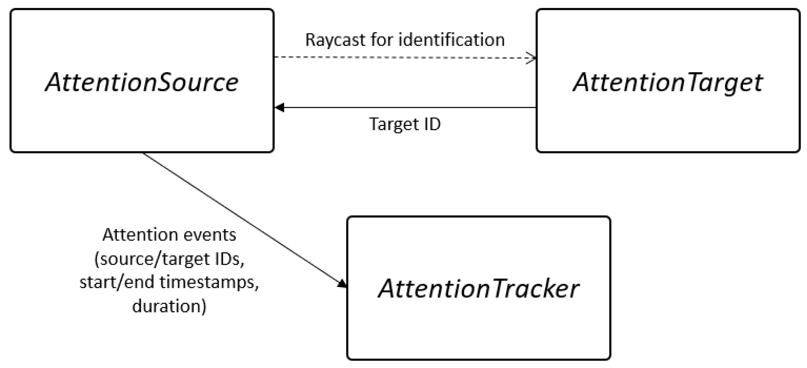
An attention tracking system was developed to record the behavior of the human subjects during the experiment. This system allows “tagged” objects in the virtual environment as attention targets, and produces reports on how long the user’s attention was directed to the specific object and at what specific moments in time. The system’s principal architecture diagram is shown in Figure 3.
The attention tracking system consists of several components, each of which corresponds to a single script written in C#. The purposes of these components are as follows:
  • AttentionTarget—a script which marks an object as a target for the attention tracking system. It is a Unity Component script, which means it can be attached to any 3D object in the virtual environment. AttentionTarget must have a trigger volume attached to it to be detected by AttentionSources.
  • AttentionSource—a script which is responsible for detecting AttentionTargets. AttentionSource uses raycasting to detect trigger volumes with associated AttentionTargets in the virtual environment. If the “line of sight”–originating from the normal surface of the HMD–check encounters an AttentionTarget, a new attention event is triggered for that object. Once this object is no longer along the line of sight for some n number of computational cycles, the attention tracking event is considered finished and its duration and timestamps (in milliseconds) for the beginning and end of the event are written into the session file for the AttentionTracker.The precision of events duration is equal to the simulation’s clock cyclek length. Here, the environment used in the experiment is executed at 120 Hz, which yields a maximum precision of 8.3 ms. AttentionSource is thus leverages head tracking as an approximation of eye tracking and attention monitoring.
  • AttentionTracker—a core script which provides methods to start and stop the recording of the attention tracking session, register attention events, and export recorded data in JSON format for later retrieval and analysis.
The DT interface is segmented into three primary zones (see Figure 4), two of which are used for controlling the robot’s actions. The interface’s header draws the operator’s attention to the robot being controlled using the DT interface. The general controls section is used to adjust system settings, including robot speeds, activating/deactivating the robot, and actuating the gripper. The joint controls section is used to adjust the orientations of the individual robot joints, starting at the tool flange (Joint 6) and moving down the kinematic chain to the base (Joint 1).
For this experiment, a Vive Pro Eye VR headset with the Vive SRanipal software development kit was used to access eye tracking data in Unity engine. Eye tracking data is usually provided as a direction of the user’s gaze, expressed in quaternions. A custom C# script was used to apply gaze direction data to objects with AttentionSource scripts attached. As a result, the operator’s gaze could be used directly to register attention events. This approach is not limited to a specific HMD model, and can be replicated using other eye tracking systems. Eye tracking is used as a measurable proxy of operator attention within the virtual environment. When using the virtual interface, eye tracking can also be leveraged as an objective measure for estimating ease-of-use of the interface (e.g., how much time is spent scanning the interface for the appropriate functions for commanding robot motions), optimizing cues for attracting operator attention (e.g., are there any visual elements that distract the operator from their work?), and can benefit future iterations of the interface design (e.g., by clustering common functions as determined by frequency analysis, or by pattern identification of common gaze shifts).

2.3.3. Stress Level Approximation

To assess stress levels of human operators in both the real and virtual environments, the operators’ heart rates were sampled during the experimental sessions using a heart rate monitor. The data was recorded for each person and then analyzed according to the flow of the experiment, identifying the operator’s reaction to different experiment stages (introduction, explaining controls, and executing the task). All heart rate readings were supplied with timestamps to help categorize the data. These values can thus be compared with the resulting NASA-TLX results to provide quantitative estimates of physical and mental loads.

3. Experimental Protocol

As described in Section 2, an industrial robot motion control routine was chosen as a candidate use case for assessing the human operators’ interactions with both the robot handheld joystick and the DT VR interface. All trials are based on a simple material handling task in which the human operators remotely control a robot to pick and place a sequence of blocks within the robot’s work volume. Both the physical and virtual interfaces have similar capabilities in that they allow the operator to move the robot’s joints, and actuate the gripper to pick up or release the blocks.

3.1. Robot Control Task

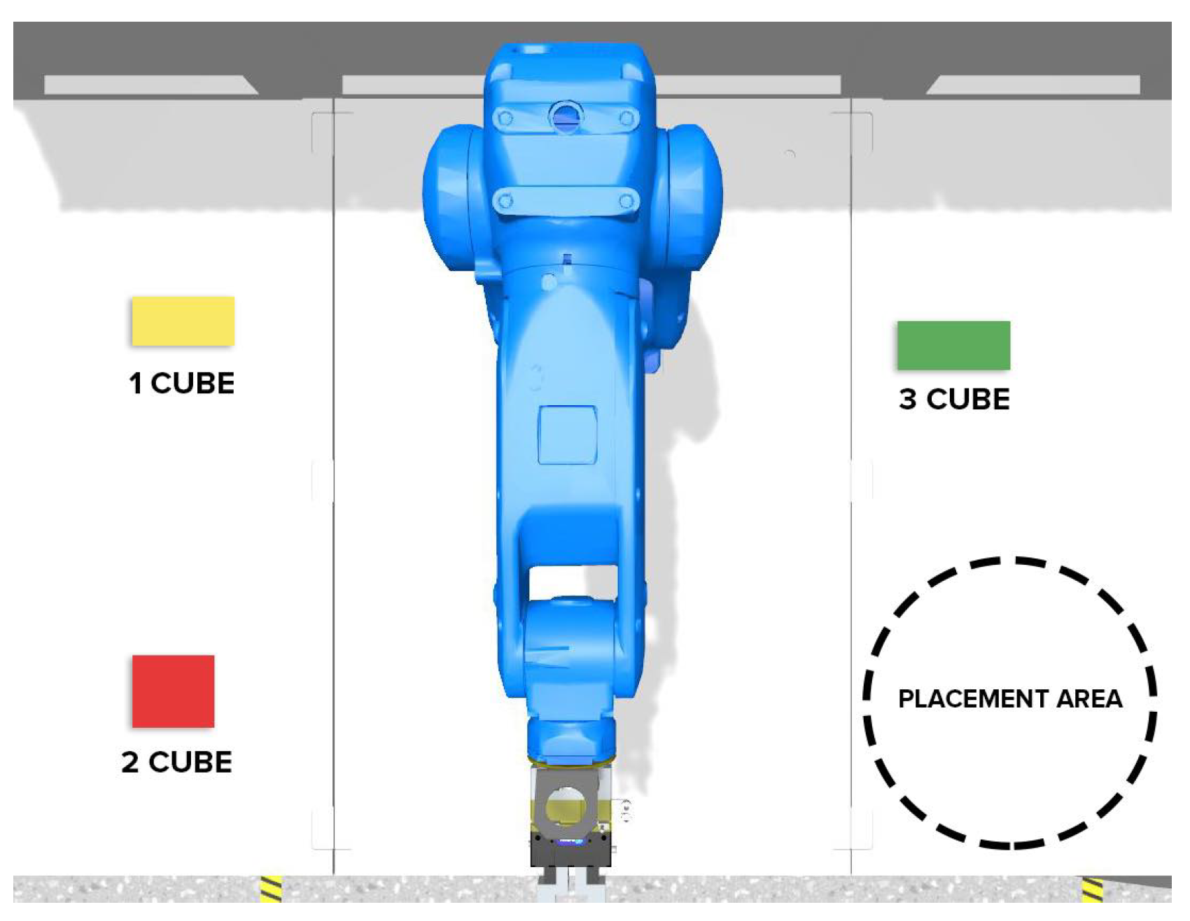
Identical tasks are used in both experimental conditions: users must control the robot to move objects, in order, from their initial positions to a target region. An operator is asked to sort the three objects by using an interface to control the robot to move to the objects, pick up the objects, and re-position the objects to a target location on the table in front of the robot (see Figure 5). Wooden cubes with different sizes were chosen as representative objects for the task. The blocks are both color-coded and labeled such that the order of the blocks is known. The operators were given minimal training on using the physical and virtual interfaces such that they could become acquainted with the controls, but not necessarily adept at using them. Following this initial training, the operators were then instructed to perform the material handling task using the interfaces specified for the operating environment. During the trials, the operators were not permitted to approach the robot. Each operator was instructed to complete the task using the physical robot, and then complete the task again using the virtual robot. After each task completion, the operator would complete the NASA-TLX and the Godspeed questionnaires. The three cubes started in the same initial poses for all trials.
For each block, the task consists of moving the robot’s gripper such that it could grasp the block. This often necessitated some trial-and-error, which could increase the completion time, but was also expected to result in net performance improvements as a function of time. Precision was necessary for grasping and lifting the blocks, but placement of the blocks did not require as much accuracy or repeatability. All robot motions after acquiring the blocks were performed in free space without obstacles, allowing the researchers to capture best-case timing such that only the operator’s ability to use the interfaces impacts the task performance. During the trials, the operator’s actions and performance were recorded to assess task performance and interface utility.

3.2. Participants

A total of forty-seven subjects volunteered for the trials, but seven volunteers did not complete the trials and are therefore excluded from reporting (therefore serial number of subjects throughout the paper is not continuous). The remaining volunteers (N = 40) were then divided into two equal groups, which differed in terms of the order in which the subjects used the different interfaces. One group evaluated the physical teach pendant interface before the DT interface, while the other evaluated the DT interface first.
For the first volunteer group (Group A, physical interface first, N A = 20 ), sixteen (16) participants identified as male, and four (4) identified as female. The sample included backgrounds from engineering, business administration, and environmental engineering bachelor and master students; engineering disciplines lecturers and researchers. The number of selected subjects was limited due to the COVID-19 quarantine period and consequent restrictions in human gatherings. The age of subjects ranged between 20 and 53 with an average age of 29.4 years. The subjects’ countries of origin were divided as follows: seven (7) from Estonia, five (5) from Ukraine, two (2) from Iran, two (2) from Turkey, one (1) from Bhutan, one (1) from Georgia, one (1) from Nigeria, and one (1) from Pakistan. Users were asked to evaluate their skills in robot programming on a scale from 1 to 10 (1 being no experience, and 10 being an expert in robotics). The average response for this group was 3.9, showing low self-assessment grade in the field of related research.
For the second volunteer group (Group B, DT interface first, N B = 20 ), seventeen (17) identified as male, and three (3) identified as female, and had an average age of 29.9 years old (with a range from 22 to 53 years old). Volunteers had different backgrounds being mainly students and researchers from different departments of Tallinn University of Technology, and one professor. The sample included eight (8) people of Estonian nationality, six (6) from Italy, one (1) from India, one (1) from Slovakia, one (1) from Turkey, one (1) from Japan, one (1) from Ukraine, and one (1) from Ecuador. The average self assessment value of expertise in robot programming scored, this time, a value of 4.2, which represents, again, quite a low expertise estimation.
Volunteers were instructed to complete the robotic object handling task over three trials for both interfaces, resulting in six trials in total per person.

4. Results

4.1. Task Timing

Table 1 shows a comparison of average completion times for both the physical and virtual interfaces for volunteers in Group A. By contrasting the average time spent by volunteers in the real-world trials versus the DT interface, it is seen that the use of the physical teach pendant generally resulted in significantly longer times to complete the robotic material handling task. This trend is observed for the manipulation of all three cubes.
Table 2 shows a comparison of average completion times for volunteers in Group B. It is seen that the resulting trends in average completion times are comparable with those in group B, with times to perform the task using the virtual interface being less than the times using the physical interface. It is also observed that Group B demonstrated better task execution performance overall. This latter observation could imply that VR-based experiment introduction and testing is more beneficial from the perspective of preparing the users to work real machinery. However, it may also be a result of the slightly higher average self-reporting robot expertise score than Group A.
To test this, two consecutive trials of volunteers performing the object handling task using the VR interface are evaluated for a subset of the volunteers. The volunteers are identified by their self-reported expertise in robotics. As seen in Table 3, which shows the task completion time using the VR interface for two consecutive trials, there does not appear to be a strong correlation between self-reported expertise in robotics and initial task performance. For example, one volunteer who self-reported their expertise level as “2” performed consistently better than a volunteer with a self-reported expertise of “9.” Some other factor (possibly experience with other machinery, video games, or similar systems) must be contributing to this discrepancy. Furthermore, the field of robotics-aerial, ground, industrial etc, were not asked as well as expertise with Virtual Reality applications, which could lead to faster learning curve towards the immersive experience of the experiment. Such information, however, was not captured in the initial surveys, and will be a subject of future study.
Regardless, it is evident that, as the volunteers use the interface more, the times to complete the task are, generally speaking, monotonically decreasing. Similar trend lines are also seen while using the physical interface, as shown in Figure 6, it is also decreasing with the same average tempo. As is seen on the figure, on average the virtual trials took less time to complete than the physical trials. This may be attributed to some experience gained during the physical trials being applied to the virtual interface and person mental readiness for the future step. Moreover, virtual environment might seems more simple for the users due to it is similarity to the computer game rather to standing next to the physical machinery.

4.2. Subjective Survey Responses

Following the trials, volunteers were asked to complete the Godspeed Survey, which captures individual perceptions and reactions to robots after interacting with them, and the NASA-TLX, which is used to measure the physical and mental effort required to complete the task.
The averaged results from Group A’s Godspeed surveys are given in Table 4. These results reveal no significant differences between the physical and virtual systems in terms of operator responses. Controlling the physical robot resulted in higher average results in terms of evaluating anthropomorphism, while the virtual environment was considered more interactive than the real setup. Likewise, the scores for perceived intelligencewere higher for the VR environment. Although the virtual environment was perceived as creating more anxiety than the real robot cell, the volunteers’ perception of safety of the two systems shows no significant differences between the two scenarios. To test for any potential impact on the order of exposure (real versus virtual), the Godspeed survey for Group A was compared with that of Group B. Results for Group B, shown in Table 5, show that while the values are slightly different between the two groups, the overall trends do not differ significantly. This implies that the order of interface experiments (physical or virtual) does not affect overall perception of the robot systems.
To contrast the results of the Godspeed questionnaire, Group A’s NASA-TLX survey results, averaged and shown in Table 6, demonstrate that the use of the VR programming environment was considered more mentally demanding, and created a higher level of frustration and required more effort than the real environment. Performance evaluation of the physical trials was also slightly higher than the virtual trials. Group B’s NASA-TLX results, Table 7, demonstrates a reversal in the perception of effort, with the physical system largely demanding more effort and resulting in higher frustration than the virtual system. This demonstrates a correlation between the order of trial evaluations and the perception of effort. Namely, that the interface the participants experienced first tended to be perceived as demanding less effort, but ultimately performed worse, than the second interface. This could infer a potential resistance to change, particularly when introducing new technologies in established processes. Additional experiments will be necessary to confirm this.

4.3. Eye Tracking

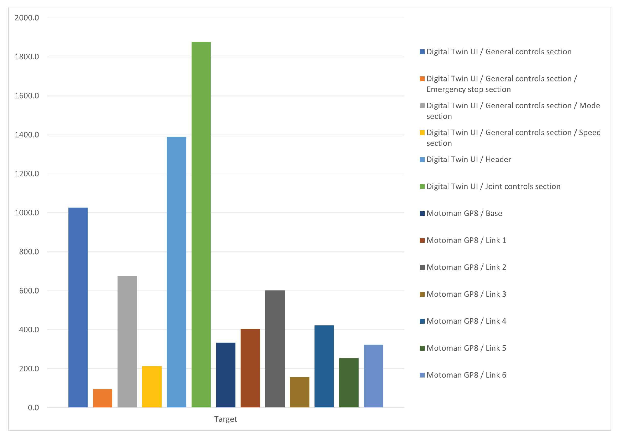
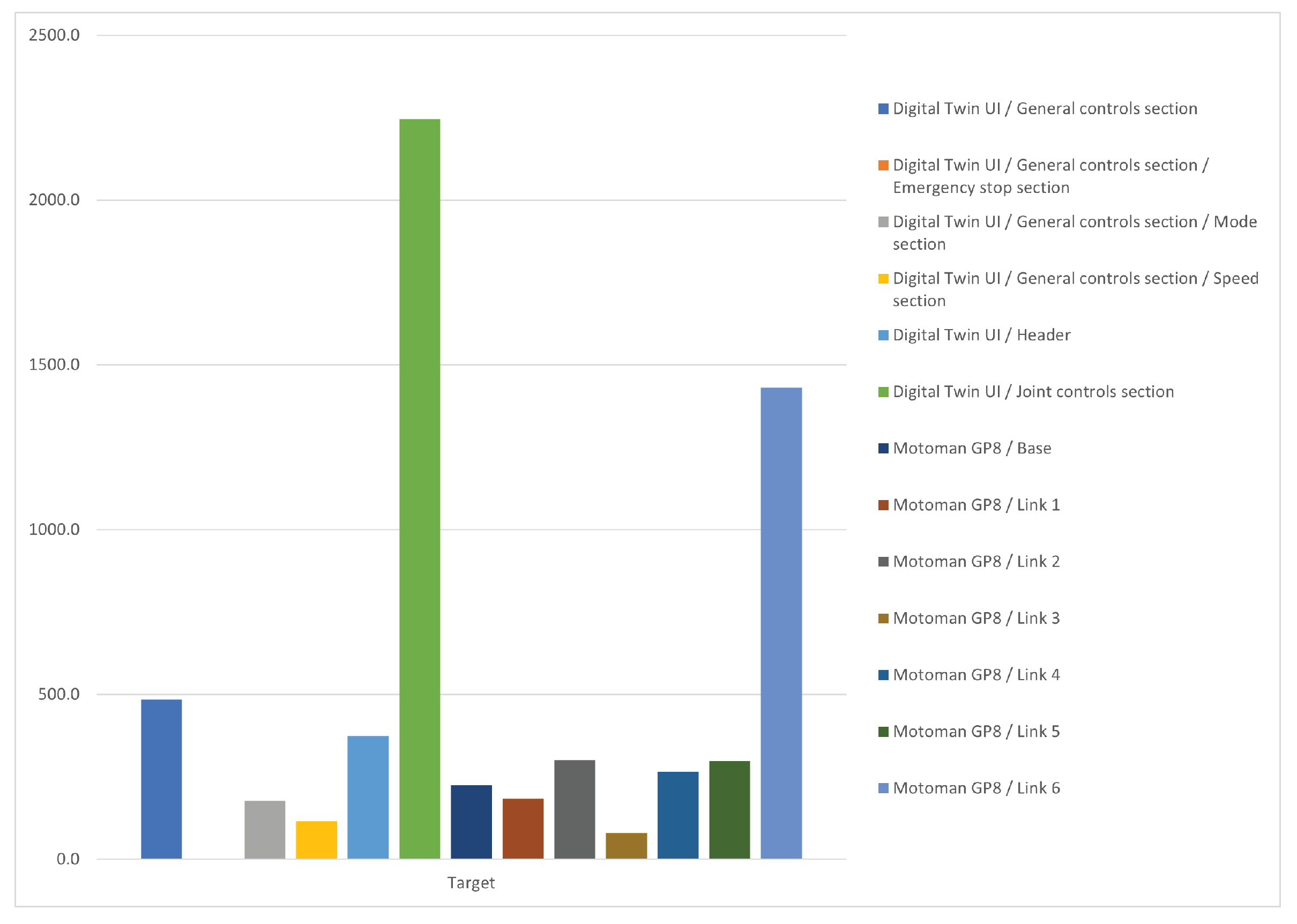
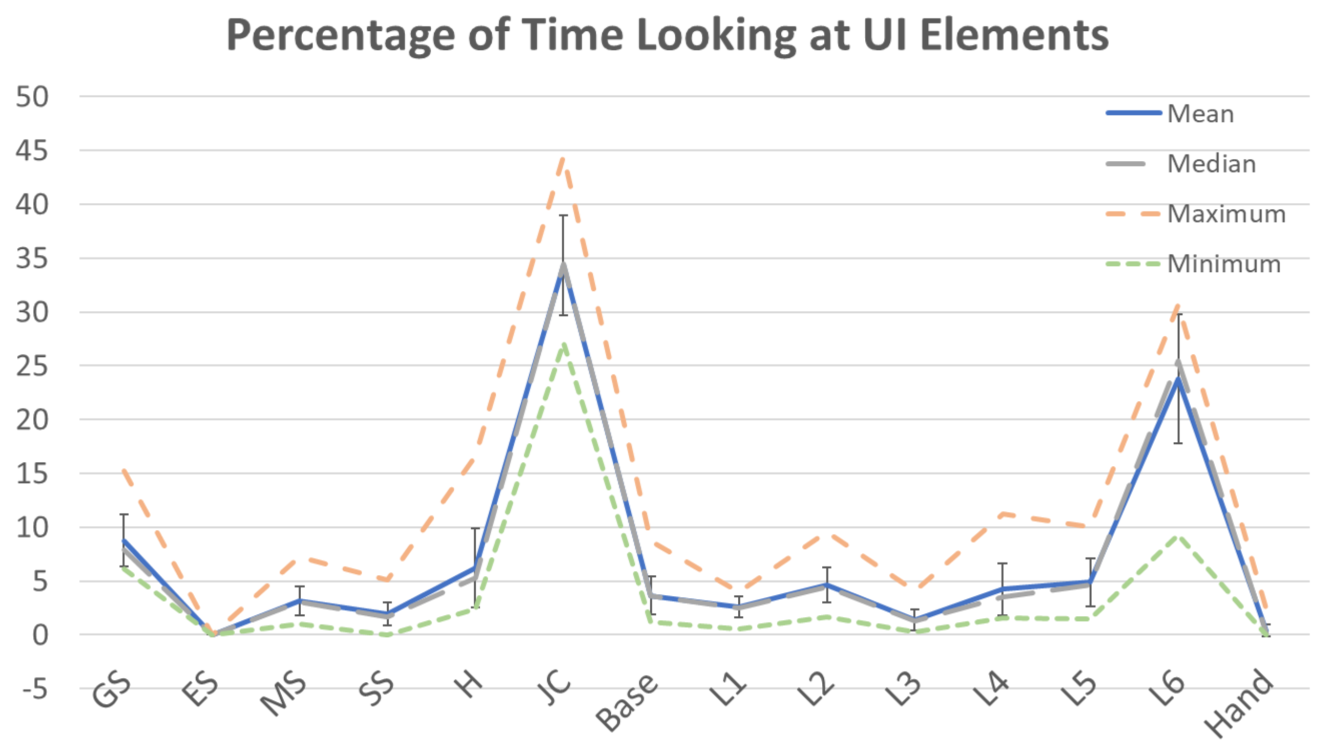
By comparing eye-tracking data collected during VR robot programming tests (Figure 7 and Table 8 for Group A, and in Figure 8 and Table 9 for Group B), it is clear that time spent looking at the UI controls is considerably higher (more than double) than time spent in looking at the virtual robot. For Group A, the regions containing the general controls, joint controls, and header are among the virtual UI targets with highest focus times. For Group B, the attention tracking system gave slightly different results. Figure 8 shows how the joint control section is still the area that was visualized for the longest time. In this case, though, timing relative to the general control section and header are much lower. In contrast, time spent looking at the physical industrial robot joint 6 is much higher than in the previous experiment.
Higher times for looking at robot joint 6 are quite understandable, as this joint is relative to the robot gripper and consequently the object to be picked and replaced. In contrast, there is no clear correlation between expertise with robots and time spent in looking at the controls or the robot in the DT. Given the comparatively short duration of the trials, drawing conclusions from the operator’s extended use of different interfaces and the focus of their gaze is inconclusive. Future works could include the evaluation of user expertise with immersive VR technologies over longer periods of time.
While the raw numbers are interesting and telling in and of themselves from an individual participant’s perspective, they do not succinctly capture the general performance of the operators during the experiment. By re-evaluating each time factor as a percentage of the total time spent using the interface, the data becomes normalized. When plotted as is shown in Figure 9 and Figure 10 it becomes clear where the operators’ attention was generally focused. Per Figure 9, a disproportionate amount of the operators’ time was spent looking at the UI header, followed closely by the joint control panel. However, it is unlikely the operators’ attention was focused this much on the header. As such, it can be surmised that the implementation of the eye tracker was somewhat flawed, with the most likely source of error being the assumption the operator’s focus is determined exclusively by the positioning of their head. The more plausible hypothesis is that the operators’ faces were pointed at the header (which is situated between the robot and the interface), and their eyes would move up or down to adjust focus on the joint controls and the robot.
A more precise implementation of eye/focus tracking would be to correlate the head position with the motions and interface usage of the pointing devices. For example, an extended period of time spent looking at the header while the pointing device is interacting with a button on the joint control panel can indicate focus on either the joint control panel, or on the robot’s joint(s) being manipulated. If there is an extended period of activity (e.g., moving the pointing device or rapidly pressing the action button), one might assume the focus was on the joint control panel. Otherwise the virtual joint is the more likely target of attention.

4.4. Physiological Stress Monitoring

Heart rate data was collected during both physical and virtual trials to assess physiological stress during the test. However, while the results for Group A (Table 10) shows a slight elevation of heart rate during physical trials, this difference is within a single standard deviation as is therefore not significant. For Group B (Table 11) results appear to be even less divergent with nearly identical average heart rate for the physical and virtual robot programming sessions. Due to the relatively low sample size, even with the slightly higher reported range for Group A, the discrepancy is likely the result of a single outlier participant, as the average is within a single standard deviation for both groups. Moreover, the source of the slower heart rate during the virtual trials could not be isolated, as it was not clear if it stemmed from operator comfort during the test, or merely the order of experimentation. This highlights yet another factor that needs addressing in future experiments. Likewise, contrasting these results with the subjective reporting in Section 4.2, there is no clear correlation between heart rate and the perception of effort.

5. Discussion

5.1. Advantages and Limitations of the DT System

Results highlighted in Section 4 imply that interacting and controlling a real robot with a traditional tech pendant is largely comparable to VR DT interface control. The VR interface shows better performance overall in terms of time spent in placing the objects with a relevant lower average time after user acquaintance with the virtual environment. Nevertheless, the VR scenario creates more anxiety, and is more demanding on the operator both mentally and physically while not considerably effecting the physiological stress level. The DT system shows promising results in terms of acceptability by the user and overall task execution performance supporting the belief that VR can be a valuable alternative to traditional robot programming interfaces.
Eye-tracking results show that user attention is more frequently directed to the main robot VR UI while not so often to the robot twin. This could probably be due to the perceived safety of the environment. With no real robot moving and being a possible source of danger, the operator might have been able to focus on the interface more without checking the robot position. This hypothesis needs to be confirmed as the precision of the attention system could be also a cause for the collected data set. Attention tracking results could also be influenced by the type of interface interaction in VR. The virtual UI needs to be constantly looked at to be able to use VR pointer selection and interaction as shown in Figure 2. A comparison between eye-tracking attention values in physical and DT trials could clarify the causes of this type of behavior in the VR DT scenario. Furthermore, the current DT control panel does not provide an option to use Inverse Kinematics (IK) when setting the robot positions. Using IK in real-time could speed up the process of working with the digitized robot and bring it on the same feature level as the real machine. Another limitation of the study is the evaluation of familiarity with HMDs, navigation, and interaction in virtual reality. Considering the positive results of task performance in users that took the test in VR twice, it would be informative to understand if improvements were produced by familiarity with the UI, or with the VR interaction and navigation system in general.

5.2. Potential Future Developments (Based on the Findings)

Throughout the analysis of the results, many new questions arose as anomalies and inconsistencies manifested. Moreover, the stated hypothesis in Section 1 could not be fully accepted and rejected and more additional studies should be performed for confirmation of it. Potential future developments of this work can possibly include running the experiment with DT in coupled mode. This could help to determine if the virtual UI allows for better performance than the teach pendant. This could support the design, implementation, and evaluation of different virtual user interfaces for the same robot but customized to different use cases and manufacturing tasks. Furthermore, an advanced programming VR UI for expert users could facilitate the comparison between the two interfaces among proficient users. As mentioned previously, the user’s level of acquaintance with VR interfaces could be considered in advance. Results show that performance time values were considerably lower after a first try of the system. Including eye-tracking in the real robot control scenario and compare results with the collected data from the VR interface would allow for further attention analysis between the teach pendant and virtual UI. Integrating and improving the proposed assessment methodology with virtual reality tools and hardware would allow for the implementation of a fast assessment tool for DT VR interfaces.
Given the results of the eye tracker implementation, it is clear the tracking solution does provide useful information in terms of accuracy, but has insufficient precision. Future efforts will attempt to eliminate the limitations of the current eye tracking approach. The proposed approach as described in Section 4.3 is planned for future implementations. Similarly, as discussed in Section 4.4, heart-rate as a surrogate for stress is currently inconclusive when contrasted with the NASA-TLX survey results. Future efforts can attempt to factor out possible sources of bias including variations in order of operations, proximity to the robot, and tasks.

6. Conclusions

Results gathered during the experiments are pretty promising in blurring the line between the virtual and physical experience of human operators when interacting with industrial robots. The collected data shows no relevant difference in operator journey between the two experimental setups. Moreover, there was no significant difference between group A and group B, which can state that the counterbalance reached its purpose in making the experimental flow more general, and the order of experimental flow did not affect the main flow-only the time of performance with group B on the physical robot was slightly different. The proposed system should be developed further, made more interactive, adapted and integrated to more use-case scenarios. Future work will try to improve the eye-tracking system setup and evaluation for a more efficient assessment of the focus of attention. Nonetheless, it can be stated that the aim of this paper was fulfilled, and research is ready to be continued in preparation for the verification and validation of standardized test methods for DT in HRI.

7. Disclaimer

Certain commercial equipment, instruments, or materials are identified in this paper to foster understanding. Such identification does not imply recommendation or endorsement by Tallinn University of Technology or the National Institute of Standards and Technology, nor does it imply that the materials or equipment identified are necessarily the best available for the purpose.

Author Contributions

Conceptualization, V.K.; Data curation, S.L.P.; Formal analysis, J.A.M. and S.L.P.; Funding acquisition, T.O.; Investigation, M.A. and M.S.; Methodology, J.A.M. and M.S.; Project administration, V.K. and T.O.; Resources, V.K. and Y.B.; Software, Y.B.; Validation, J.A.M., M.A. and S.L.P.; Visualization, M.A. and Y.B.; Writing—original draft, V.K. and S.L.P.; Writing—review & editing, J.A.M. and T.O. All authors have read and agreed to the published version of the manuscript.

Funding

The research was conducted using the Smart Industry Centre (SmartIC) core facility funded by the Estonian Research Council grant TT2. Additionally, supported by the EU Regional Development Fund and by the Estonian Research Council under grant PSG453 “Digital twin for propulsion drive of an autonomous electric vehicle”.

Institutional Review Board Statement

Not applicable.

Informed Consent Statement

Informed consent was obtained from all subjects involved in the study.

Data Availability Statement

The data presented in this study are available on request from the corresponding author.

Acknowledgments

The research was conducted using the Smart Industry Centre (SmartIC) core facility funded by the Estonian Research Council grant TT2. Additionally, supported by the EU Regional Development Fund and by the Estonian Research Council under grant PSG453 “Digital twin for propulsion drive of an autonomous electric vehicle”. Additionally, authors are grateful to student Marietta Gavriljuk, who did aid with the experimental process.

Conflicts of Interest

The authors declare no conflict of interest.

References

  1. Liu, M.; Fang, S.; Dong, H.; Xu, C. Review of digital twin about concepts, technologies, and industrial applications. J. Manuf. Syst. 2020, 58, 346–361. [Google Scholar] [CrossRef]
  2. Villani, V.; Pini, F.; Leali, F.; Secchi, C. Survey on human–robot collaboration in industrial settings: Safety, intuitive interfaces and applications. Mechatronics 2018, 55, 248–266. [Google Scholar] [CrossRef]
  3. Berg, J.; Lu, S. Review of Interfaces for Industrial Human-Robot Interaction. Curr. Robot. Rep. 2020, 1, 27–34. [Google Scholar] [CrossRef] [Green Version]
  4. Krupke, D.; Steinicke, F.; Lubos, P.; Jonetzko, Y.; Görner, M.; Zhang, J. Comparison of multimodal heading and pointing gestures for co-located mixed reality human–robot interaction. In Proceedings of the 2018 IEEE/RSJ International Conference on Intelligent Robots and Systems (IROS), Madrid, Spain, 1–5 October 2018; pp. 1–9. [Google Scholar]
  5. Hart, S.G.; Staveland, L.E. Development of NASA-TLX (Task Load Index): Results of empirical and theoretical research. Adv. Psychol. 1988, 52, 139–183. [Google Scholar]
  6. Brooke, J. SUS-A “quick and dirty” usability scale. Usability Eval. Ind. 1996, 189, 4–7. [Google Scholar]
  7. Hassenzahl, M.; Burmester, M.; Koller, F. AttrakDiff: Ein Fragebogen zur Messung wahrgenommener hedonischer und pragmatischer Qualität. In Mensch & Computer 2003; Springer: Berlin/Heidelberg, Germany, 2003; pp. 187–196. [Google Scholar]
  8. Whitney, D.; Rosen, E.; Phillips, E.; Konidaris, G.; Tellex, S. Comparing robot grasping teleoperation across desktop and virtual reality with ROS reality. In Robotics Research; Springer: Berlin/Heidelberg, Germany, 2020; pp. 335–350. [Google Scholar]
  9. Tadeja, S.K.; Lu, Y.; Seshadri, P.; Kristensson, P.O. Digital Twin Assessments in Virtual Reality: An Explorational Study with Aeroengines. In Proceedings of the 2020 IEEE Aerospace Conference, Missoula, MT, USA, 7–14 March 2020; pp. 1–13. [Google Scholar]
  10. Kennedy, R.S.; Lane, N.E.; Berbaum, K.S.; Lilienthal, M.G. Simulator sickness questionnaire: An enhanced method for quantifying simulator sickness. Int. J. Aviat. Psychol. 1993, 3, 203–220. [Google Scholar] [CrossRef]
  11. Rheinberg, F.; Engeser, S.; Vollmeyer, R. Measuring components of flow: The Flow-Short-Scale. In Proceedings of the 1st International Positive Psychology Summit, Washington, DC, USA, 3–6 October 2002. [Google Scholar]
  12. Schubert, T.; Friedmann, F.; Regenbrecht, H. Igroup presence questionnaire. Teleoperators Virtual Environ. 2001, 41, 115–124. [Google Scholar]
  13. Laaki, H.; Miche, Y.; Tammi, K. Prototyping a Digital Twin for Real Time Remote Control Over Mobile Networks: Application of Remote Surgery. IEEE Access 2019, 7, 20325–20336. [Google Scholar] [CrossRef]
  14. Concannon, D.; Flynn, R.; Murray, N. A Quality of Experience Evaluation System and Research Challenges for Networked Virtual Reality-Based Teleoperation Applications. In Proceedings of the 11th ACM Workshop on Immersive Mixed and Virtual Environment Systems; Association for Computing Machinery, MMVE’19, New York, NY, USA, 18 June 2019; pp. 10–12. [Google Scholar] [CrossRef]
  15. Matsas, E.; Vosniakos, G.C.; Batras, D. Effectiveness and acceptability of a virtual environment for assessing human–robot collaboration in manufacturing. Int. J. Adv. Manuf. Technol. 2017, 92, 3903–3917. [Google Scholar] [CrossRef]
  16. Oyekan, J.O.; Hutabarat, W.; Tiwari, A.; Grech, R.; Aung, M.H.; Mariani, M.P.; López-Dávalos, L.; Ricaud, T.; Singh, S.; Dupuis, C. The effectiveness of virtual environments in developing collaborative strategies between industrial robots and humans. Robot. Comput.-Integr. Manuf. 2019, 55, 41–54. [Google Scholar] [CrossRef]
  17. Sievers, T.S.; Schmitt, B.; Rückert, P.; Petersen, M.; Tracht, K. Concept of a Mixed-Reality Learning Environment for Collaborative Robotics. Procedia Manuf. 2020, 45, 19–24. [Google Scholar] [CrossRef]
  18. Yap, H.J.; Taha, Z.; Dawal, S.Z.M.; Chang, S.W. Virtual reality based support system for layout planning and programming of an industrial robotic work cell. PLoS ONE 2014, 9, e109692. [Google Scholar]
  19. Malik, A.A.; Masood, T.; Bilberg, A. Virtual reality in manufacturing: Immersive and collaborative artificial-reality in design of human–robot workspace. Int. J. Comput. Integr. Manuf. 2020, 33, 22–37. [Google Scholar] [CrossRef]
  20. Pérez, L.; Rodríguez-Jiménez, S.; Rodríguez, N.; Usamentiaga, R.; García, D.F. Digital Twin and Virtual Reality Based Methodology for Multi-Robot Manufacturing Cell Commissioning. Appl. Sci. 2020, 10, 3633. [Google Scholar] [CrossRef]
  21. Peruzzini, M.; Grandi, F.; Pellicciari, M. Exploring the potential of Operator 4.0 interface and monitoring. Comput. Ind. Eng. 2020, 139, 105600. [Google Scholar] [CrossRef]
  22. Karwowski, W. The OCRA Method: Assessment of Exposure to Occupational Repetitive Actions of the Upper Limbs. In International Encyclopedia of Ergonomics and Human Factors-3 Volume Set; CRC Press: Boca Raton, FL, USA, 2006; pp. 3337–3345. [Google Scholar]
  23. Havard, V.; Jeanne, B.; Lacomblez, M.; Baudry, D. Digital twin and virtual reality: A co-simulation environment for design and assessment of industrial workstations. Prod. Manuf. Res. 2019, 7, 472–489. [Google Scholar] [CrossRef] [Green Version]
  24. McAtamney, L.; Corlett, N. Rapid upper limb assessment (RULA). In Handbook of Human Factors and Ergonomics Methods; CRC Press: Boca Raton, FL, USA, 2004; pp. 86–96. [Google Scholar]
  25. Rosen, E.; Whitney, D.; Phillips, E.; Chien, G.; Tompkin, J.; Konidaris, G.; Tellex, S. Communicating robot arm motion intent through mixed reality head-mounted displays. In Robotics Research; Springer: Berlin/Heidelberg, Germany, 2020; pp. 301–316. [Google Scholar]
  26. Moniri, M.M.; Valcarcel, F.A.E.; Merkel, D.; Sonntag, D. Human gaze and focus-of-attention in dual reality human–robot collaboration. In Proceedings of the 2016 12th International Conference on Intelligent Environments (IE), London, UK, 14–16 September 2016; pp. 238–241. [Google Scholar]
  27. Wassermann, J.; Vick, A.; Krüger, J. Intuitive robot programming through environment perception, augmented reality simulation and automated program verification. Procedia CIRP 2018, 76, 161–166. [Google Scholar] [CrossRef]
  28. Vosniakos, G.C.; Ouillon, L.; Matsas, E. Exploration of two safety strategies in human–robot collaborative manufacturing using Virtual Reality. Procedia Manuf. 2019, 38, 524–531. [Google Scholar] [CrossRef]
  29. Maragkos, C.; Vosniakos, G.C.; Matsas, E. Virtual reality assisted robot programming for human collaboration. Procedia Manuf. 2019, 38, 1697–1704. [Google Scholar] [CrossRef]
  30. Manou, E.; Vosniakos, G.C.; Matsas, E. Off-line programming of an industrial robot in a virtual reality environment. Int. J. Interact. Des. Manuf. 2019, 13, 507–519. [Google Scholar] [CrossRef]
  31. Pérez, L.; Diez, E.; Usamentiaga, R.; García, D.F. Industrial robot control and operator training using virtual reality interfaces. Comput. Ind. 2019, 109, 114–120. [Google Scholar] [CrossRef]
  32. Ostanin, M.; Klimchik, A. Interactive Robot Programming Using Mixed Reality. IFAC-PapersOnLine 2018, 51, 50–55. [Google Scholar] [CrossRef]
  33. Nathanael, D.; Mosialos, S.; Vosniakos, G.C. Development and evaluation of a virtual training environment for on-line robot programming. Int. J. Ind. Ergon. 2016, 53, 274–283. [Google Scholar] [CrossRef]
  34. Ong, S.; Yew, A.; Thanigaivel, N.; Nee, A. Augmented reality-assisted robot programming system for industrial applications. Robot. Comput.-Integr. Manuf. 2020, 61, 101820. [Google Scholar] [CrossRef]
  35. Burghardt, A.; Szybicki, D.; Gierlak, P.; Kurc, K.; Pietruś, P.; Cygan, R. Programming of Industrial Robots Using Virtual Reality and Digital Twins. Appl. Sci. 2020, 10, 486. [Google Scholar] [CrossRef] [Green Version]
  36. Kuts, V.; Otto, T.; Tähemaa, T.; Bondarenko, Y. Digital twin based synchronised control and simulation of the industrial robotic cell using virtual reality. J. Mach. Eng. 2019, 19, 128–144. [Google Scholar] [CrossRef] [Green Version]
  37. Marvel, J.A.; Bagchi, S.; Zimmerman, M.; Antonishek, B. Towards Effective Interface Designs for Collaborative HRI in Manufacturing: Metrics and Measures. ACM Trans. Hum.-Robot. Interact. 2020, 9, 1–55. [Google Scholar] [CrossRef]
  38. Bartneck, C.; Kulic, D.; Croft, E.A. Measuring the anthropomorphism, animacy, likeability, perceived intelligence and perceived safety of robots. In Proceedings of the Metrics for Human-Robot Interaction, ACM/IEEE International Conference on Human-Robot Interaction, Amsterdam, The Netherlands, 12–15 March 2008; ACM: Amsterdam, The Netherlands, 2008. [Google Scholar]
  39. ISO 25010; Systems and Software Engineering-Systems and Software Quality Requirements and Evaluation (SQuaRE)-System and Software Quality Models. International Organization for Standardization: Geneva, Switzerland, 2011.
  40. Kuts, V.; Modoni, G.E.; Otto, T.; Sacco, M.; Tähemaa, T.; Bondarenko, Y.; Wang, R. Synchronizing physical factory and its digital twin throughan iiot middleware: A case study. Proc. Est. Acad. Sci. 2019, 68, 364–370. [Google Scholar] [CrossRef]
  41. Kuts, V.; Cherezova, N.; Sarkans, M.; Otto, T. Digital Twin: Industrial robot kinematic model integration to the virtual reality environment. J. Mach. Eng. 2020, 20, 53–64. [Google Scholar] [CrossRef]
Figure 1. The design of experiments utilizes both physical and virtual representations of the work cell. The physical trials (left) involve the operator using the robot’s teach pendant to manipulate the end-of-arm tooling. The virtual trials use a VR interface (right) for commanding robot motions.
Robotics 11 00113 g001
Figure 2. The user interface of the industrial robot cell DT. The interface is a large panel located in front of the robot, and is manipulated using a hand-held pointing device.
Robotics 11 00113 g002
Figure 3. Architecture of the attention tracking system.
Robotics 11 00113 g003
Figure 4. The three primary zones of the DT UI are the header (top), the general controls (left), and the joint controls (right).
Robotics 11 00113 g004
Figure 5. Configuration of the the block manipulation task experiment.
Robotics 11 00113 g005
Figure 6. Average positioning time comparison per cube for both physical and virtual interfaces.
Robotics 11 00113 g006
Figure 7. Total seconds spent viewing targets in VR for Group A.
Robotics 11 00113 g007
Figure 8. Total seconds spent viewing targets in VR for Group B.
Robotics 11 00113 g008
Figure 9. Average operator use of the interface, plotting the mean, median, maximum, and minimum amounts of time spent focusing on different parts of the UI for Group A. The error bars represent a single standard deviation from the mean. The labels on the horizontal axis are those introduced in Table 8.
Robotics 11 00113 g009
Figure 10. Average operator use of the interface, plotting the mean, median, maximum, and minimum amounts of time spent focusing on different parts of the UI for Group B. The error bars represent a single standard deviation from the mean. The labels on the horizontal axis are those introduced in Table 8.
Robotics 11 00113 g010
Table 1. Average task completion time, in seconds, for Group A (physical interface first).
Cube Re-Positioning TaskAverage Physical Machine DurationAverage VR Process Duration
Cube #1225144
Cube #2210115
Cube #3184105
Table 2. Average task completion time, in seconds, for Group B (Virtual interface first).
Cube Re-Positioning TaskAverage VR Process DurationAverage Physical Machine Duration
Cube #1114178
Cube #292130
Cube #361159
Table 3. Sub-task completion times (in seconds) of subjects with different self-reported experience in robotics using the VR interface.
Trial 1
Expertise in robotics (1–10)2912
1 cube end360120180120
2 cube end24012012090
3 cube end6018012090
Trial 2
1 cube end3001206060
2 cube end240606045
3 cube end60456045
Table 4. Godspeed survey results comparison, real versus virtual robots, for Group A.
Anthropomorphism-Scale 1–5PhysicalVirtual
Fake-Natural42.65
Machine-like-Human-like2.62.5
Unconscious-Conscious2.452.3
Artificial-Lifelike2.552.15
Moving Rigidly-Moving Elegantly3.252.75
Animacy-Scale 1–5PhysicalVirtual
Dead-Alive2.52.4
Stagnant-Lively2.852.85
Mechanical-Organic2.32.25
Artificial-Lifelike2.31.9
Inert-Interactive2.753.35
Apathetic-Responsive3.43.45
Likeability-Scale 1–5PhysicalVirtual
Dislike-Like43,.5
Unfriendly-Friendly3.553.3
Unkind-Kind3.43.35
Unpleasant-Pleasant3.63.55
Awful-Nice3.93.55
Perceived Intelligence-Scale 1–5PhysicalVirtual
Incompetent-Competent3.23.3
Ignorant-Knowledgeable2.953.45
Irresponsible-Responsible3.453.5
Unintelligent-Intelligent2.93.2
Foolish-Sensible3.13.25
Perceived Safety-Scale 1–5PhysicalVirtual
Anxious-Relaxed4.13.55
Agitated-Calm3.853.9
Quiescent-Surprised2.953.05
Table 5. Godspeed survey results comparison, real versus virtual robots, for Group B.
Anthropomorphism-Scale 1–5VirtualPhysical
Fake-Natural3.553.45
Machine-like-Human-like1.951.9
Unconscious-Conscious2.352.3
Artificial-Lifelike2.452.2
Moving Rigidly-Moving Elegantly3.053.45
Animacy-Scale 1–5VirtualPhysical
Dead-Alive2.92.45
Stagnant-Lively3.23
Mechanical-Organic2.251.85
Artificial-Lifelike2.42.05
Inert-Interactive4.13.35
Apathetic-Responsive4.253.7
Likeability-Scale 1–5VirtualPhysical
Dislike-Like4.453.8
Unfriendly-Friendly3.953.1
Unkind-Kind3.73.1
Unpleasant-Pleasant3.953.35
Awful-Nice4.33.65
Perceived Intelligence-Scale 1–5VirtualPhysical
Incompetent-Competent3.653.2
Ignorant-Knowledgeable3.453.05
Irresponsible-Responsible3.33.15
Unintelligent-Intelligent3.22.8
Foolish-Sensible3.353.15
Perceived Safety-Scale 1–5VirtualPhysical
Anxious-Relaxed3.72.6
Agitated-Calm3.82.95
Quiescent-Surprised3.73
Table 6. Comparison of the average results from the post-task NASA-TLX surveys for Group A. Participant responses are given on a Likert scale of 0 to 10, representing the ranges shown in the left column.
CriteriaScalePhysicalVirtual
Mental DemandLow-High4.555.5
Physical DemandLow-High2.9252.575
Temporal DemandLow-High4.353.75
PerformanceGood-Poor3.1253.5
EffortLow-High3.4254.325
FrustrationLow-High3.1754.125
Table 7. Comparison of the average results from the post-task NASA-TLX surveys for Group B. Operator responses are given on a Likert scale of 0 to 10, representing the ranges shown in the left column.
CriteriaScaleVirtualPhysical
Mental DemandLow-High4.356
Physical DemandLow-High2.254.65
Temporal DemandLow-High4.075.55
PerformanceGood-Poor3.854.55
EffortLow-High4.076.25
FrustrationLow-High2.14.75
Table 8. Eye tracking analysis of subjects use times (in seconds) for Group A, as reported as the digital twin UI, the virtual robot, and the operator’s digitized body parts (Self; here, it is the operator’s hand). The UI is segmented into the general controls, header (H), and joint controls (JC). The general controls are further segmented into emergency stop (ES), mode selection (MS), and speed selection (SS). The Robot is segmented per major component, specifically the base, joints 1–6 (J1–J6).
Target
User InterfaceRobotSelf
General Controls
Sub. # ESMSSSHJCBaseJ1J2J3J4J5J6Hand
nr.338.4915.2813.495.7721.57117.4615.7713.7225.985.4850.7960.599.120.13
nr.5244.867.7201.444.3812.52534.920.660.140.100000
nr.622.722.1513.627.56112.4228.8239.0853.4950.042.386.462.394.240
nr.70.9600.709.060.2615.213.26.391.271.870.322.570
nr.816.1906.61051.491.85.342.082.040006.250
nr.938.9019.81.7211462.90.790.211.370.730.470.132.580
nr.1029.5022.975.11208.5141.03112160.19194.1539.0371.726.8229.463.84
nr.1160.713.6146.921.128113.424.277.92616111086.31.51
nr.1534.940.4827.367.8971.4490.322.372.234.100001.84
nr.1613116.171.631.712017313.94.012.690.040.10.378.50.12
nr.1722.02013.880177.6822.62.360.693.831.261.791.292.60
nr.1916.93.148.766.1752.831.557.552.451.700.480.712.580.17
nr.2015.72013.352.0751.9426.274.727.1714.053.5616.577.748.080
nr.2155.19.3534.516.317.91150.180.150.1200001.86
nr.221.9200.1109.1600.929.5734.4231.0811.642.62.570
nr.2344.786.8629.878.762.14141.40.350.02000000
nr.2435.12012.341.27199.6326.8321.244.364.240.060.640.361.10
nr.2558.43.9140.743.179.9943.523.6555.07127.4846.8699.9740.2866.296.25
nr.2626.739.0912.819.9749.9760.194.110.960.730001.480
nr.27130.748.55119.354.726.71791.021.11.100000
Table 9. Eye tracking analysis of subjects use times (in seconds) for Group B, as reported as the digital twin UI, the virtual robot, and the operator’s digitized body parts (Self; here, it is the operator’s hand). The UI is segmented into the general controls, header (H), and joint controls (JC). The general controls are further segmented into emergency stop (ES), mode selection (MS), and speed selection (SS). The Robot is segmented per major component, specifically the base, joints 1–6 (J1–J6).
Target
User InterfaceRobotSelf
General Controls
Sub. # ESMSSSHJCBaseJ1J2J3J4J5J6Hand
nr.121.8607.483.175.4469.444.234.118.864.2115.8117.2864.820
nr.210.0703.073.382.7623.182.471.413.641.382.101.6510.890
nr.370.08026.2518.4160.93433.3333.5538.9647.883.0118.7425.02174.9123.68
nr.424.11010.894.1719.75107.1116.4214.1421.516.0916.5923.0788.351.31
nr.517.8506.033.0722.1657.0413.073.706.320.462.302.1815.200
nr.618.5207.374.0410.8841.035.674.605.781.162.374.2745.730
nr.716.29012.7809.1449.264.404.477.051.359.0313.3649.171.11
nr.827.41010.547.3147.4480.4411.943.174.861.3610.0110.2268.311.76
nr.929.25012.168.1612.75153.438.7616.6128.517.6739.4747.69112.090.02
nr.1014.1104.032.966.8767.369.083.214.932.076.3110.5744.030.78
nr.1110.3602.791.717.2740.575.153.54.190.702.825.2828.540.01
nr.1239.1606.717.4735.49248.7333.6625.2630.946.7630.4935.78137.635.26
nr.1314.2602.862.876.3964.823.524.5312.106.139.4411.9559.931.53
nr.1425.47010.3011.7234.35119.129.717.5015.205.2210.29.7489.670.05
nr.1530.68010.947.7914.2293.0016.6312.0114.721.988.6410.2577.722.15
nr.1623.9406.154.3619.10125.4212.285.4510.475.6711.4715.4791.140.41
nr.179.9903.340.825.5630.951.170.493.791.565.717.1724.620
nr.1834.53014.368.5625.70228.7219.7914.2424.973.0514.8516.61140.371.43
nr.1918.3305.733.3010.9482.125.985.1710.753.857.698.172.662.21
nr.2027.81012.1512.0916.92130.907.5110.8834.9414.9841.2922.2534.120.21
Table 10. Heart rate values during physical and virtual robot programming for Group A.
ProcessMaximum (BPM)Minimum (BPM)Average (BPM)SD
Physical robot programming1177590.0511.99
Virtual robot programming1057685.057.53
Table 11. Heart rate values during physical and virtual robot programming for Group B.
ProcessMaximum (BPM)Minimum (BPM)Average (BPM)SD
Physical robot programming998390.554.27
Virtual robot programming1007990.16.66
Publisher’s Note: MDPI stays neutral with regard to jurisdictional claims in published maps and institutional affiliations.