Abstract
In this paper, the design and testing of a novel valve for the intuitive spatial control of soft or continuum manipulators are presented. The design of the valve is based on the style of a hydraulic flapper valve, but with simultaneous control of three pressure feed points, which can be used to drive three antagonistically arranged hydraulic actuators for positioning soft robots. The variable control orifices are arranged in a rotationally symmetric radial pattern to allow for an inline mounting configuration of the valve within the body of a manipulator. Positioning the valve ring at various 3D configurations results in different pressurizations of the actuators and corresponding spatial configurations of the manipulator. The design of the valve is suitable for miniaturization and use in applications with size constraints such as small soft manipulators and surgical robotics. Experimental validation showed that the performance of the valve can be reasonably modeled and can effectively drive an antagonistic arrangement of three actuators for soft manipulator control.
1. Introduction
The use of soft robotic manipulators has been explored for many applications where the inherently compliant nature of the device provides improved functionality. Some particularly interesting examples include graspers and minimally invasive surgical tools [1,2], where a common theme emerges in the need for the delicate handling of breakable objects or human tissues. When it comes to the control of soft manipulators, there are a wide variety of techniques, with electroactive polymers or pneumatic power being common and, to a lesser extent, emerging devices based on hydraulic power [3,4,5,6,7]. The use of hydraulic power enables robotic devices with a higher power-to-weight ratio and thus a greater payload capacity. However, there exists a gap between conventional fluidics at the meso-scale (mm to cm) and the techniques of traditional microfluidics at the micro-scale (µm to mm) that includes the type of high pressure–low flow rate fluid power components that would be necessary for the application of hydraulic power to use in soft robotics [8,9,10]. This is particularly true in surgical robotics where anatomical size constraints can restrict devices to the millimeter scale [11,12,13]. This paper describes the design of a flow control valve targeted at miniature surgical applications and specifically a natural orifice surgical robot described in Berg, 2013 [11]. With this potential valve application in mind, the scale of the present device is such that the overall diameter is less than 25 mm and the valve orifices range from less than 1 mm to 1.5 mm.
The ability to control the flow of the fluid is essential to any hydraulic system. Typically, this is achieved through the use of valves which can control whether the flow is ON or OFF and possibly the rate at which the fluid is flowing. The method by which flow is stopped can include rotational motion such as in a rotary valve, linear motion such as in spool or poppet valves, or with a flapper-nozzle valve that acts parallel to the flow direction. Additionally, proportional control can be achieved through varying the size of the valve opening or by control of an ON/OFF valve. Either method carries advantages and disadvantages. A proportional valve may provide more straight forward control methods; however, it introduces additional difficulties, such as power consumption, which can be particularly troublesome for small scale applications. Alternatively, an ON/OFF valve may have a simpler design but considerations must be made for inertial and transitional losses. Another possible solution is the use of digital hydraulics which enables a near analog output using digital or ON/OFF components [14]. There has been a significant amount of research committed to the design and evaluation of flow control valves. However, this area is particularly relevant for applications where valve miniaturization is helpful due to limited space availability within the device, such as is likely to be the case for soft robots. Much of the research in microfluidic valves makes use of any one of a short list of enabling technologies including electrostatic, magnetic, piezoelectric, thermal, chemical, or pneumatic methods [15,16,17,18,19,20]. Of these options, possible valve operation methods, such as piezoelectric or electrostatic, can provide interesting solutions to the problem of flow control and have been explored extensively for control of pneumatic systems [21,22]. For many applications, microfluidic devices do not provide sufficient flow rates to enable devices that are simultaneously small and fast. Two methods presented in the literature include the use of magnetics for valve actuation [23,24]. Peirs et al. investigated the use of both electromagnetic and piezoelectric methods for valve manipulation [25].
Presented here is a description and validation of a novel hydraulic valve capable of providing actuation pressure control simultaneously to three hydraulic actuators in an antagonistic arrangement as is often found in multi-directional articulating soft manipulators. This is achieved with the a single valve element with three degree-of-freedom movements. For the purposes of experimental validation, the valve was tested using a soft manipulator of common design. The rest of the paper is organized as follows. In Section 2, we describe the design principle for a novel hydraulic flapper valve for the control of soft or continuum robotic manipulators, which provides an intuitive control mapping between the actuation of the valve and the corresponding output at the manipulator. In Section 3, we describe a realization of this valve design based on a radially symmetric configuration and we further describe the relationship between the valve geometry and the valve control in Section 3. A prototype of this valve was developed and validated in Section 4 and Section 5, respectively, which demonstrated the ability to drive a soft robotic manipulator using an inverse mapping between the valve ring position and the corresponding motion of the actuator. A summary of the findings, Section 6, and a description of future improvements, Section 7, is included.
2. Control Valve Design
To achieve precise manipulation of soft or continuum manipulators using a hydraulic power source, it is necessary to obtain a control valve that will provide a controllable actuator pressure while occupying as little space as possible within the device. A review of the available commercial valves and common microfluidic valve solutions was conducted and no existing valve design was found suitable for small-scale applications due to the limitations of supply pressure, proportional control, and method of activation. Therefore, development of a novel control valve capable of manipulating high pressure flows with a small footprint was performed.
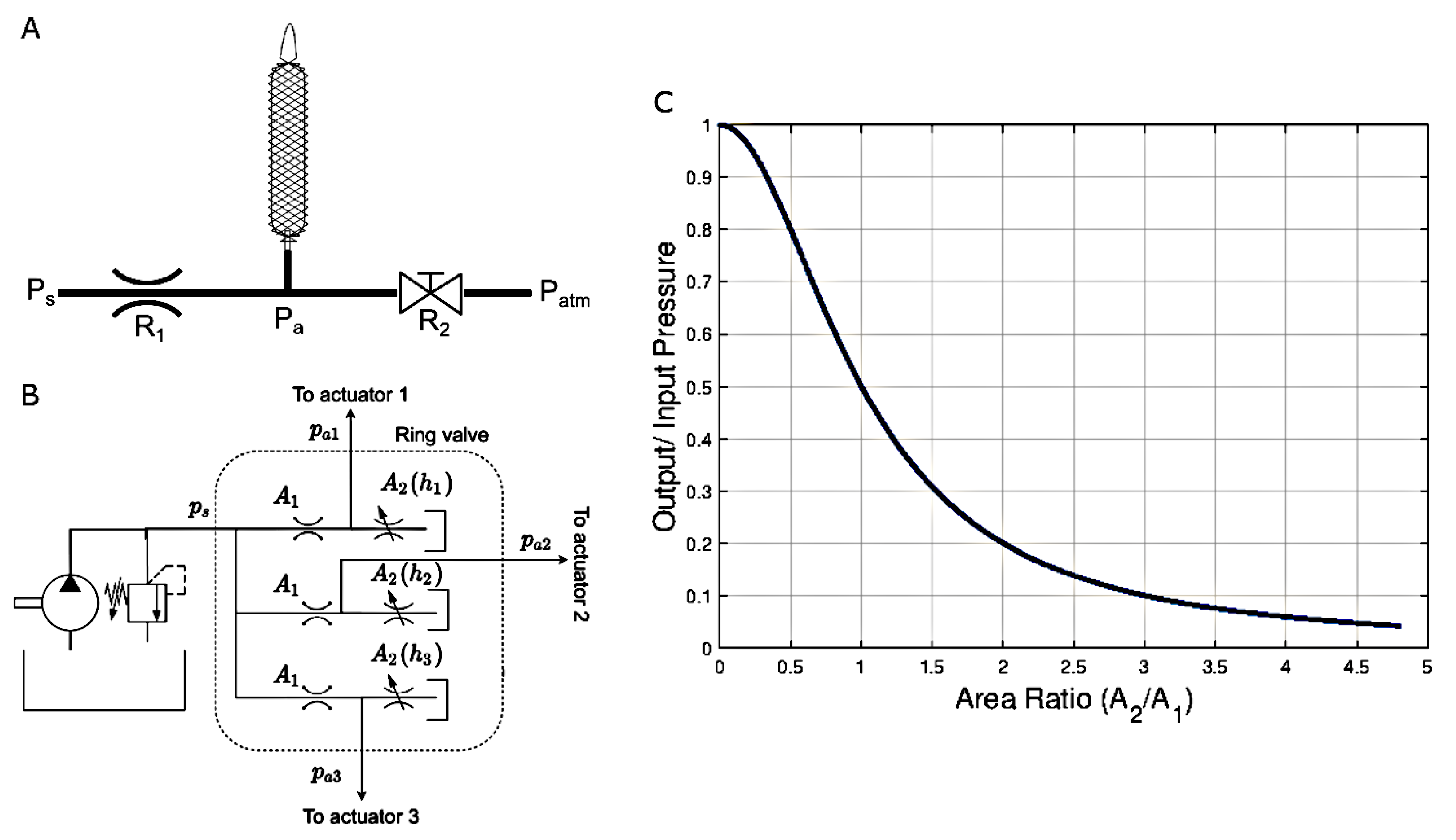
For the applications described here, the outlet of the valve could be connected to an actuator such as an artificial muscle actuator [26] or soft-robot fluid chamber. To provide useful manipulation, it is the feed pressure, , to the actuator that must be regulated by the valve such that the force produced by the actuator, which is proportional to , can be manipulated. In most soft or continuum manipulators, the manipulator is driven by an arrangement of actuation units. Each hydraulic actuator provides mono-directional force only and thus an arrangement of three actuators at a minimum is often used, operated differentially and antagonistically such that the manipulator can operate in three-dimensional space using three hydraulic actuators. For a given continuum manipulator segment, an arrangement of three actuators spaced at intervals around the central axis are common for achieving manipulator control, noting that the over-actuated, four-actuator design is also common [27]. The design of the valve makes use of the same arrangement and mode of operation such that the manipulation of the valve is directly and intuitively mapped to the operation of the manipulator since both the valve and the manipulator have three inputs and are both operated differentially and antagonistically. For each of the actuators, a simple hydraulic circuit such as is shown in Figure 1A can be used. This circuit consists of an upstream, high-pressure supply, , and a fixed-orifice flow restriction, , as well as a downstream variable-orifice flow restriction, , and a return to atmosphere, . Between the two flow restrictions is the feed point for the actuator, . By adjusting the downstream restriction relative to the fixed, upstream restriction it is then possible to manipulate the pressure at the actuator feed point as a pressure divider. For this purpose, a flapper-style valve can be used as a variable orifice [28]. With appropriately sized orifices, the flapper position would then act as the input for manipulating the downstream orifice within its available stroke range.
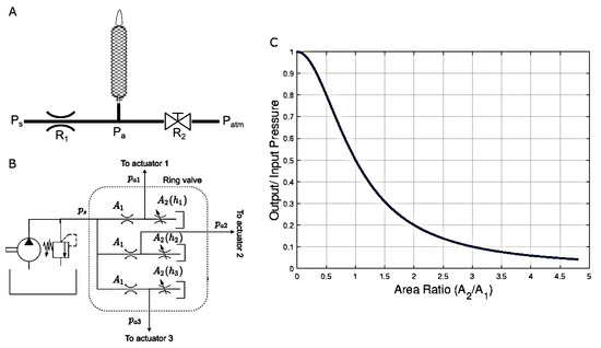
Figure 1.
Hydraulic circuit concept for (A) control of a single actuator and (B) of the three-actuator ring valve. (C) Relationship between actuated pressure ratio and area ratio assuming Equation (3).
This style of valve has the advantages of low complexity and insensitivity to contaminants in the fluid [28]. Additionally, one of the basic principles of a flapper style valve is that there is a constant leakage flow. Thus the supply must be capable of accommodating the leakage. This presents little concern as the flow rate required to inflate actuators of this scale is typically significantly smaller than the available flow rate of the supply. On the other hand, there is an added advantage in terms of safety through limiting the supply flow and hence the actuation speed.
The hydraulic circuit for the valve design presented here consists of three parallel circuits for the three degrees of freedom of the soft actuator supplied by a common pressure supply (Figure 1B). Each parallel circuit is a pressure divider consisting of a fixed orifice and an variable orifice in series. This configuration is used for example in the pilot stage of a servo-valve. In our case, all three variable orifices are controlled by the position of a common flapper, described further in Section 3. Using the standard orifice equation and the flow continuity equation, and assuming that the flow rate to the actuator is negligible (which is reasonable under static or quasi-static conditions), we have, for each parallel circuit,
where Q is the flow rate, is the supply pressure, is the actuator pressure, k is the valve coefficient, is the area of the fixed orifice, and is the variable orifice area at a gap h. Simplifying, we have:
which says that the actuator pressure decreases from the supply pressure as the variable orifice’s opening increases. In our case, the fixed orifice has a radius of , so that . The variable downstream opening has a radius of . A rough estimate of the orifice area, which ignores that the valve opening is on a curved surface, is the skirt area:
where h is the gap distance between the surface of the downstream orifice and the inner diameter of the ring. The resulting relationship of the actuated pressure ratio and area ratio is shown in Figure 1C.
3. Description of Valve Realization
Realization of this valve design could take many forms. However, for applications such as soft robotics, continuum manipulators, or other robots with similar functions, a compact size for all components is often desirable. With this in mind, a realization (Figure 2A) of the flapper style valve design was developed [29]. This design uses a radial configuration in which the supply enters the valve at the center and exits radially as shown in Figure 2B. With this design, the orifices are located on the outer diameter of the valve body and are opened or closed using a ring-shaped flapper which is manipulated radially.

Figure 2.
(A) Model of ring based flapper valve design and (B) model showing part of the flow path for both the closed (top) and open (bottom) variable orifice conditions. In (B), the ring has been omitted for clarity of presentation. (C) is the inner diameter of the ring that is manipulated based on axial position, z. The center of the ring is offset from the center of the valve body. describe the angle of the offset relative to a reference line on the hub. is the radial offset which is the distance between the center of the valve and the center of the ring, . , and are the orifices on the valve body. The gap distances, , , are distances between points and , and , and and . The figure is not to scale and is for illustrative purposes only.
This valve design is normally open such that the majority of the flow bypasses the actuator and dumps to the return line. When the manipulated ring is activated in a particular in-plane direction, the orifices are activated differentially: the orifice(s) that the ring gets closer to become more restrictive, and the corresponding actuator pressures increase; the orifice(s) that the ring gets further away from becomes less restrictive, and the corresponding actuator pressures decrease. This in turn produces a directional actuation of the manipulator in the direction of activation. Out of plane movement of the ring pressurizes or de-pressurizes all of the actuators simultaneously. This has the effect of increasing or decreasing the manipulator’s stiffness and also provides the ability to independently manipulate the pressure at the three actuator feed points.
Relationship between Ring Geometry and Gap Distance
Each of the three orifice openings is dependent on the gap distance, which is in turn a function of the ring position as illustrated in Figure 2C. The valve body on which the variable orifices are located apart is represented by the small circle. The tapered ring is represented by the larger circle. Figure 2C is not to scale to exaggerate the gap distances. The valve body is constrained to be within the ring. Since only the relative position matters, the valve body moves while the ring stays at a constant location in this mathematical model.
Three parameters are used to describe the configuration of the ring relative to the valve body:
- Axial position, : This is the movement of the ring in and out of the plane of Figure 2C. Since the ring has a taper angle of and the minimum diameter is , the diameter of the ring at the plane of the nozzles is given by:
- Radial offset, or normalized offset, : The offset is the distance between the centers of the valve body and of the ring. We define to be the offset normalized by , which is the maximum possible offset for that axial position z. determines the maximum and minimum gap distances as the ring rotates, such that:
- Ring angle, : This is the angle between the line from the center of the valve body to the third orifice () and the extended line from the center of the ring to the center of the valve body (the extension of the segment ). The angle, , increases from as the ring rotates relative to the valve body in the anti-clockwise manner. See Figure 3A,B for two examples of ring positions.
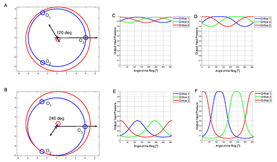 Figure 3. Examples of two ring positions at its maximum axial position with (A) normalized radial offset and ; (B) normalized radial offset and . Predicted pressure ratios when (min) and (C) , (D) . Predicted pressure ratios when (max) and (E) , (F) .
Given , the three gap distances, , , and , can be calculated from geometry.
Assuming the orifice areas are predicted by Equation (3), the relationships between the ring position and the pressure ratio at the actuator under different conditions are plotted in Figure 3C–F.
At , , and , the ring fully covers each one out of the three downstream orifices as shown in the peak of each graph at those angles. There are higher and lower intersection points in the graphs. The angle at the higher intersection point is when the ring is placed equally in the middle of two orifices while the angle at the lower intersection point is when the ring is fully covering one orifice, leaving the other two orifices at an equivalent lower pressure. The simulations show that, as the axial position and radial offset increase, the range in between the maximum and minimum pressure increases. It also shows how the ring can be used to cover one orifice individually or two orifices simultaneously.
Figure 4 illustrates how different valve ring configurations affect a continuum manipulator actuated by three hydraulic artificial muscles whose pressures are controlled by the valve ring. The three artificial muscles are arranged circumferentially and are apart. When the muscle is pressurized, it pulls on the continuum robot towards it (see [11] for details). Notice that the valve angle, , determines which direction the manipulator bends and the axial position, z, and actual offset, , control the amount of bending.
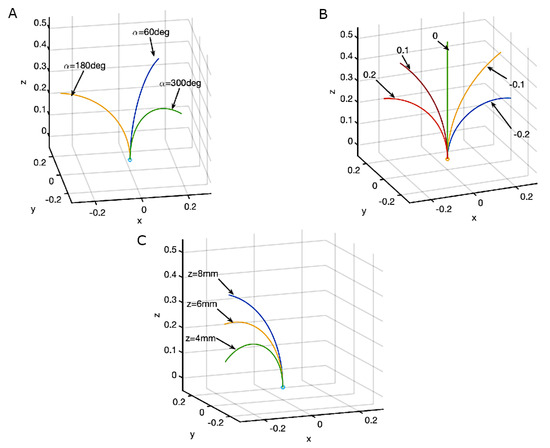
Figure 4.
Effect of the valve positions on a continuum manipulator. (A): Varying , mm, ; (B): Varying , mm and ; (C): Varying z, , and the offsets all 3 are the same as for at mm.
4. Valve Prototype
A representative prototype of the valve design, shown in Figure 5A, was fabricated using traditional subtractive machining operations. The design of the valve geometry is such that both the high-pressure supply and the low-pressure return lines can connect to the valve body in a direction parallel to the longitudinal axis of the valve. This method of connection keeps the overall size requirements of the valve in the radial direction as small as possible. One realization of this method of connection would employ a hydraulic line with the cross-section shown in Figure 5B, where the black areas represent the tubing material and the inner white areas represent the multiple lumens of the tubing. This tubing is then connected to the base of the valve body such that the outer two lumens pass over the lower portion of the valve body and are sealed to the valve at the distal outer diameter as shown in Figure 5C. The inner lumen connects to the base of the valve body using the barbed fitting. The hydraulic supply and return are then able to behave as was shown in Figure 2B. The use of this style of tubing permits the option of supplying the valve by running the tubing down the length of the manipulator working channel thus maintaining the overall footprint of the manpulator and allowing the valve to be located near the manipulator’s actuation.

Figure 5.
(A) Machined prototype of the ring-based control valve design. (B) Example cross-section of a multi-lumen tubing used to provide both feed and return lines for the control valve. (C) Illustration of valve connection to the hydraulic supply and return lumens of the described tubing for the ring-based valve design.
5. Experimental Validation
5.1. Characterization of the Individual Orifice
Each of the three orifices is characterized for their effect on the actuator pressure. An experimental test rig (Figure 6) was constructed in which each orifice can be opened or closed using a servo motor with a screw attached. The tip of each screw has a square rubber gasket so that as the screw moves, the rubber gasket opens or closes the flapper orifice. The range of linear travel is 0.56 mm. At every gap distance, pressure at the actuator corresponding to its orifice is recorded and the results are shown in Figure 7A.
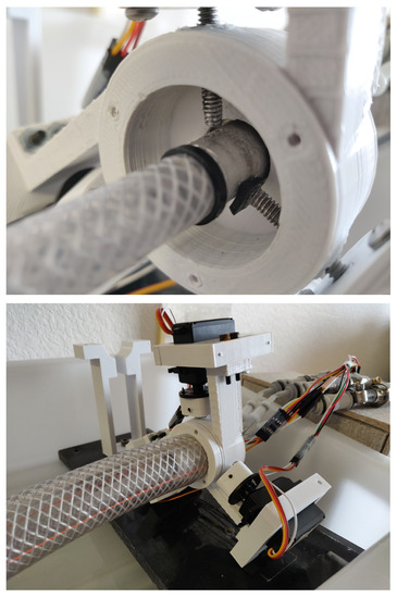
Figure 6.
Experimental rig in which each orifice can be individually opened or closed using a servo motor driving a screw.
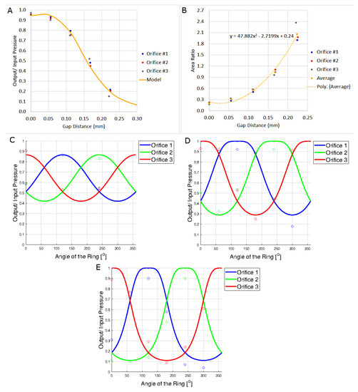
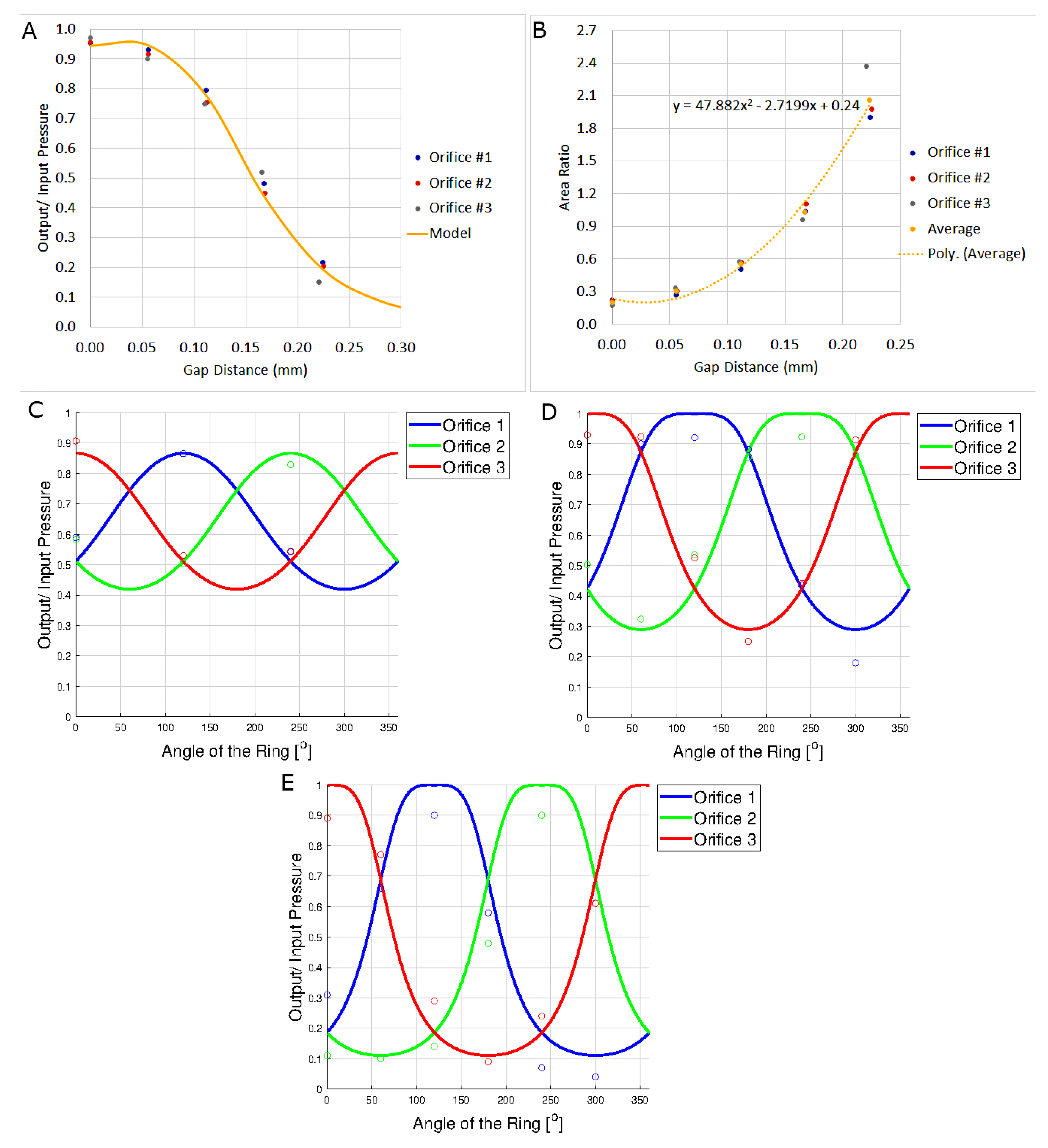
Figure 7.
(A) Actuator to input pressure ratio versus gap distance for each orifice. (B) Calibrated area ratios as a function of gap distance. (C) Relationship between the angle of the servo motor simulated ring and pressure ratio at axial position of 4 mm (mid-position of the ring) and radial offset of 0.5. Marker ‘o’ represents the experimental results taken at different angles of the ring. Lines represent the orifice equation (Equation (1)) relationship at axial position of 4 mm and radial offset of 0.5. (D) Relationship between the angle of the servo motor simulated ring and pressure ratio at axial position of 4 mm (mid-position of the ring) and radial offset of 1. (E) Relationship between the angle of the actual ring and pressure ratio at axial position of 4 mm (mid-position of the ring) and radial offset of 1.
The results show that the three orifices perform similarly, as expected, as the orifices are equivalent. After characterizing the orifices individually, we obtained effective orifice areas as a function of the gap distance. This is achieved by matching the gap distance with an orifice area that would produce the experimentally observed actuator pressure ratio in Figure 7A according to Equation (2) (or Figure 1C). The results as shown in Figure 7B show that the smaller the gap distance, the smaller effect the valve has on the pressure ratio. Notice that this relationship is not linear and would have been difficult to predict from geometry alone. The experimental results also show that the valve is overall more sensitive as it requires less travel distance to move the pressure ratio from 1 to 0 compared to the prediction of Equation (2). Equation (2) requires 0.39 mm to get to pressure ratio of 0.2 from 1 while the experimental set up only requires 0.22 mm. As shown in Figure 7A, using this relationship, the theoretical pressure ratio and gap distance relationship as predicted by Equation (2) matches the experimental results quite well.
5.2. Simulated Ring Manipulation
Next, the ring is simulated by adjusting the three gap distances simultaneously using the three servo motors. By using the model, the servo motors move accordingly to mimic the orifice equation relationship between the pressure ratio and the area ratio. The pressure ratios for two different radial offsets of 0.5 and 1, and a total of nine angular positions at a fixed axial position of 4 mm were investigated as shown in Figure 7C,D.
The results align qualitatively with the model. However, there are some variations quantitatively that could be caused by error in the servo motor position, stiffening of the rubber gaskets and the gasket’s ability to fully cover an orifice at a radial offset of 1. For example, in Figure 7D, the maximum pressure ratio is 0.93, which suggests that the experimental setup is not able to fully seal the orifice and fluid losses exist between the orifice and the actuator.
5.3. Manual Manipulation of the Physical Ring
Lastly, the machined ring (see Figure 5A) is positioned by hand to cover the orifices at the maximum axial position of 8 mm and radial offset of 1. The ring is moved and pushed against the orifices at different angles. The results are presented in Figure 7E.
The results showed that the ring performed qualitatively as expected. The ring also has a maximum pressure ratio of about 0.9, suggesting that the machined ring is unable to fully seal the orifice. This could potentially be remedied by the application of a compliant material to the inner surface of the ring to compensate for the imperfect surface finish and geometry variations between the ring and the valve body.
5.4. Use of the Ring Valve for Soft-Robotic Control
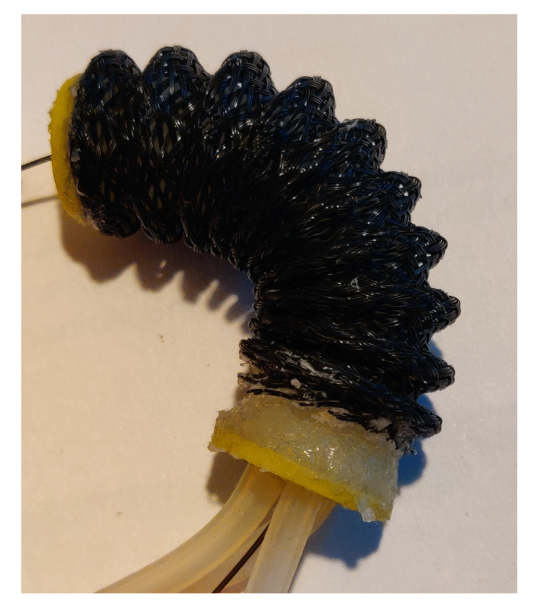
To validate the functionality of ring-based flapper valve with the soft-robotic actuator, a soft actuator was fabricated as shown in Figure 8, which is based on the Soft Robotics Toolkit [30]. The soft actuator consists of three equivalent embedded fluid chambers arranged apart. As the pressure in one of the chambers increases, the chamber expands and causes the soft actuator to bend in the opposite direction. If two chambers are inflated, the soft actuator bends in the opposite direction of the mid-point of the two inflated chambers. When the pressures of all three chambers increase at the same time, the soft actuator will extend forward. The soft actuator has an external braided sheath to improve motion capabilities by preventing over-inflation of the chambers.
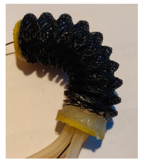
Figure 8.
Soft actuator based on the Multi-Module Variable Stiffness Manipulator and used for experimental validation of the valve.
With the spatial arrangement of the chambers being aligned with the orifices location, one can control the movement of the actuator intuitively. As the ring moves to restrict one orifice, the pressure of the corresponding chamber increases and bend in the same direction of the ring. As the ring moves forward to restrict all three orifices, the actuator extends forward and vice versa. The design of the ring-based flapper valve allows an intuitive control as the actuators move in the same direction as the ring.
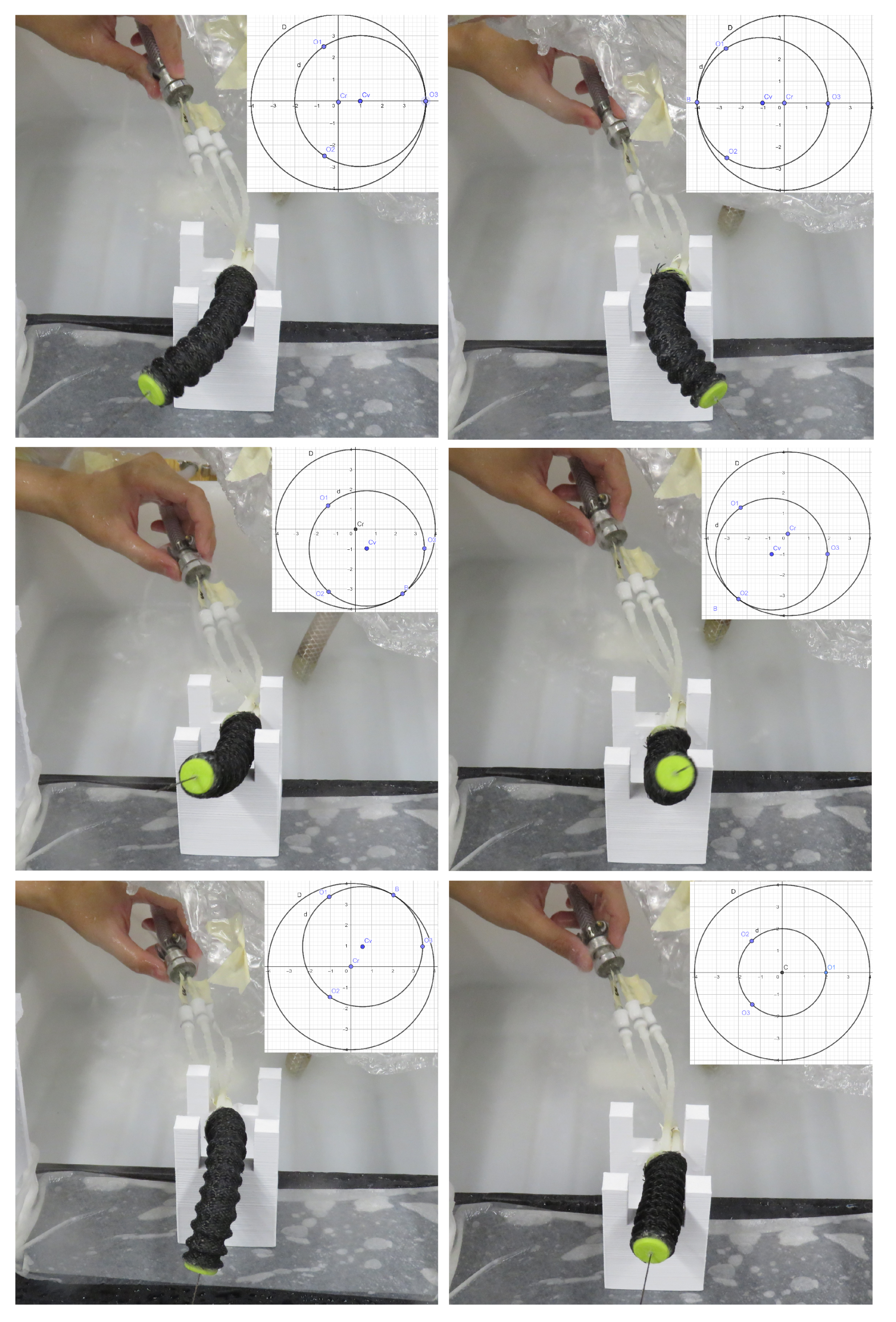
For testing of the ring-based flapper valve, the pressure sensors were removed and replaced with the soft robotic actuator. The ring was positioned by hand at different angles to control the movement of the soft robotic actuator. As the pressure increases in one chamber, the soft robotic actuator moves in the opposite direction as shown in Figure 9. This validation also shows that the current ring-based flapper valve design allows one-handed manual operation in controlling the movement of the soft actuator.
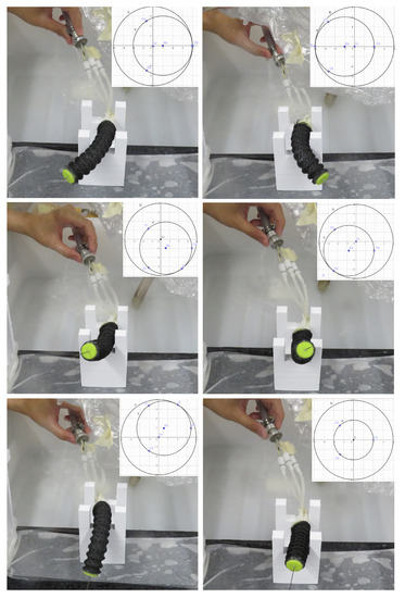
Figure 9.
Manipulation of the soft-robot by positioning the ring at different positions and angles, resulting in the soft-robot being drive to various corresponding positions.
6. Summary of Control Valve Design
The ring-based flapper valve works qualitatively as expected, controlling the output pressures of each chamber in the soft actuator based on the ring position. A smaller area of the orifice opening results in a higher actuated pressure, as expected. The more proximate the axial position of the ring, the larger the area of orifice openings, and the lower the actuated pressures. The ring is able to cover one orifice, two orifices, or three orifices at a time, allowing for the pressurization of one, two, or three fluid chambers simultaneously. The design of the ring-based flapper valve and the actuator show the ease of use as one can control the actuator intuitively as the actuator moves in the same direction as the ring. The results show that both the ring simulation with rubber gaskets and the machined ring require smaller area of orifice opening to fully pressurize the soft actuator compared to the theoretical data from the orifice equation (Equation (1)).
However, due to the limitations in the experimental set up for a sensitive valve, the results were not consistent and have a large range of uncertainty. The machined ring performed differently from the theoretical data but closely to the characterization data from the servo motor driven ring simulation. A better experimental set up with a more precise ring positioning mechanism will verify the characteristics of the ring determined from this research.
7. Conclusions
This paper presents the design and experimental validation of a valve designed for use with continuum and soft robotic manipulators. This type of manipulator commonly makes use of three antagonistic degrees of freedom per manipulator section to achieve position control. The valve design provides intuitive, simultaneous antagonistic control to match the operation mode of the manipulators.
A few improvements in the ring based flapper valve design, such as increasing the relative size of the downstream orifice for a less sensitive valve body, adding locating features on the valve body that can set the valve body in a known orientation and fixed position for better ring positioning, adding attachment features for the ring positioning mechanism on the valve body to use the valve body as a reference point for ring positioning, adding features on the ring to allow firm and aligned attachment to the ring positioning mechanism, lining the inner side of the ring with rubber gasket for a better seal, and the use of a stiffer actuator, shall be considered for the next steps in this research. At the current size scale, the valve may be mounted inline or near the distal end of many soft manipulators, particularly in robotic devices suitable for surgical applications. Further miniaturization of this valve design is possible as permitted by manufacturing capability. With additional miniaturization of the valve, it is also necessary to achieve greater precision in the ring positioning system, which may be achieved through linear actuation or other precision drive systems.
The present work was focused on the initial valve design and validation. Future work is required to develop a better understanding of the valve dynamics and stability as well as to develop a control algorithm to more precisely map the valve ring positioning to the anticipated manipulator motion.
Author Contributions
Conceptualization, K.L., D.R.B. and P.Y.L.; methodology, K.L., D.R.B. and P.Y.L.; software, K.L., D.R.B. and P.Y.L.; validation, K.L. and P.Y.L.; formal analysis, K.L., D.R.B. and P.Y.L.; investigation, K.L., D.R.B. and P.Y.L.; writing—original draft preparation, K.L., D.R.B. and P.Y.L.; writing—review and editing, K.L., D.R.B. and P.Y.L.; visualization, K.L., D.R.B. and P.Y.L.; supervision, P.Y.L.; project administration, P.Y.L. All authors have read and agreed to the published version of the manuscript.
Funding
The APC was funded by the G.A. Taft Endowment, Stout University Foundation.
Institutional Review Board Statement
Not applicable.
Informed Consent Statement
Not applicable.
Data Availability Statement
Not applicable.
Conflicts of Interest
The authors declare no conflict of interest.
References
- Homberg, B.S.; Katzschmann, R.K.; Dogar, M.R.; Rus, D. Robust proprioceptive grasping with a soft robot hand. Auton. Robot. 2019, 43, 681–696. [Google Scholar] [CrossRef] [Green Version]
- Runciman, M.; Darzi, A.; Mylonas, G.P. Soft robotics in minimally invasive surgery. Soft Robot. 2019, 6, 423–443. [Google Scholar] [CrossRef] [PubMed] [Green Version]
- George Thuruthel, T.; Ansari, Y.; Falotico, E.; Laschi, C. Control strategies for soft robotic manipulators: A survey. Soft Robot. 2018, 5, 149–163. [Google Scholar] [CrossRef] [PubMed]
- Bar-Cohen, Y.; Anderson, I.A. Electroactive polymer (EAP) actuators—Background review. Mech. Soft Mater. 2019, 1, 1–14. [Google Scholar] [CrossRef] [Green Version]
- Gu, G.; Shea, H.; Seelecke, S.; Alici, G.; Rizzello, G. From the Topic Editors: Soft Robotics based on Electroactive Polymers Authors. Front. Robot. AI 2021, 8, 122. [Google Scholar] [CrossRef]
- Padovani, D.; Barth, E.J. Design and Characterization of a Miniature Hydraulic Power Supply for High-Bandwidth Control of Soft Robotics. In Proceedings of the 2020 3rd IEEE International Conference on Soft Robotics (RoboSoft), New Haven, CT, USA, 15 May–15 July 2020; pp. 345–350. [Google Scholar]
- Park, T.; Kim, K.; Oh, S.R.; Cha, Y. Electrohydraulic actuator for a soft gripper. Soft Robot. 2020, 7, 68–75. [Google Scholar] [CrossRef] [PubMed]
- Love, L.; Lind, R.; Jansen, J. Mesofluidic actuation for articulated finger and hand prosthetics. In Proceedings of the 2009 IEEE/RSJ International Conference on Intelligent Robots and Systems, St. Louis, MO, USA, 10–15 October 2009; pp. 2586–2591. [Google Scholar]
- Ho, C.; Tai, Y. Micro-electro-mechanical-systems (MEMS) and fluid flows. Annu. Rev. Fluid Mech. 1998, 30, 579–612. [Google Scholar] [CrossRef] [Green Version]
- Whitesides, G. The origins and the future of microfluidics. Nature 2006, 442, 368–373. [Google Scholar] [CrossRef] [PubMed]
- Berg, D.R. Design of a Hydraulic Dexterous Manipulator for Minimally Invasive Surgery. Ph.D. Thesis, University of Minnesota, Minneapolis, MN, USA, 2013. [Google Scholar]
- Pourghodrat, A.; Nelson, C.A. Disposable fluidic actuators for miniature in-vivo surgical robotics. J. Med Devices 2017, 11, 011003. [Google Scholar] [CrossRef] [PubMed] [Green Version]
- Pourghodrat, A.; Nelson, C.A.; Oleynikov, D. Hydraulic Robotic Surgical Tool Changing Manipulator. J. Med Devices 2017, 11, 011008. [Google Scholar] [CrossRef] [PubMed] [Green Version]
- Linjama, M.; Vilenius, M. Digital hydraulics—Towards perfect valve technology. In Proceedings of the Tenth Scandinavian International Conference on Fluid Power, Tampere, Finland, 21–23 May 2007; Volume 1, pp. 181–196. [Google Scholar]
- Studer, V.; Hang, G.; Pandolfi, A.; Ortiz, M.; Anderson, W.; Quake, S. Scaling properties of a low-actuation pressure microfluidic valve. J. Appl. Phys. 2004, 95, 393–398. [Google Scholar] [CrossRef] [Green Version]
- Luque, A.; Quero, J.; Hibert, C.; Flückiger, P.; Gañán-Calvo, A. Integrable silicon microfluidic valve with pneumatic actuation. Sens. Actuators A Phys. 2005, 118, 144–151. [Google Scholar] [CrossRef]
- Baek, J.; Park, J.; Ju, J.; Lee, T.; Lee, S. A pneumatically controllable flexible and polymeric microfluidic valve fabricated via in situ development. J. Micromech. Microeng. 2005, 15, 1015–1020. [Google Scholar] [CrossRef]
- Selvaganapathy, P.; Carlen, E.; Mastrangelo, C. Electrothermally actuated inline microfluidic valve. Sens. Actuators A Phys. 2003, 104, 275–282. [Google Scholar] [CrossRef]
- Huff, M.; Mettner, M.; Lober, T.; Schmidt, M. A pressure-balanced electrostatically-actuated microvalve. In Proceedings of the IEEE Solid-State Sensor and Actuator Workshop, 4th Technical Digest, Hilton Head, SC, USA, 4–7 June 1990; pp. 123–127. [Google Scholar]
- Sounart, T.; Michalske, T. Electrostatic actuation without electrolysis in microfluidic MEMS. In Proceedings of the 12th International Conference on Transducers, Solid-State Sensors, Actuators and Microsystems, Boston, MA, USA, 8–12 June 2003; pp. 615–618. [Google Scholar]
- Ohnstein, T.; Fukiura, T.; Ridley, J.; Bonne, U. Micromachined silicon microvalve. In Proceedings of the IEEE Conference on Micro Electro Mechanical Systems, Napa Valley, CA, USA, 11–14 February 1990; pp. 95–98. [Google Scholar]
- Fikru, N.; Chase, T. A review of MEMS based pneumatic valves. In Proceedings of the 2011 52nd National Conference on Fluid Power, Beijing, China, 7–20 August 2011; pp. 271–282. [Google Scholar]
- Fu, C.; Rummler, Z.; Schomburg, W. Magnetically driven micro ball valves fabricated by multilayer adhesive film bonding. J. Micromech. Microeng. 2003, 13, S96. [Google Scholar] [CrossRef]
- Pernod, P.; Preobrazhensky, V.; Merlen, A.; Ducloux, O.; Talbi, A.; Gimeno, L.; Viard, R.; Tiercelin, N. MEMS magneto-mechanical microvalves (MMMS) for aerodynamic active flow control. J. Magn. Magn. Mater. 2010, 322, 1642–1646. [Google Scholar] [CrossRef]
- Peirs, J. Design of miniature parallel manipulators for integration in a self-propelling endoscope. Sens. Actuators A Phys. 2000, 85, 409–417. [Google Scholar] [CrossRef]
- Schulte, H. The characteristics of the McKibben artificial muscle. In The Application of External Power in Prosthetics and Orthotics; National Academy of Sciences—National Research Council: Washington, DC, USA, 1961; pp. 94–115. [Google Scholar]
- Webster III, R.J.; Jones, B.A. Design and kinematic modeling of constant curvature continuum robots: A review. Int. J. Robot. Res. 2010, 29, 1661–1683. [Google Scholar] [CrossRef]
- Merritt, H. Hydraulic Control Systems; John Wiley & Sons Inc.: Hoboken, NJ, USA, 1967. [Google Scholar]
- Berg, D.R. Ring valve design files. Figshare 2017. [Google Scholar] [CrossRef]
- Falco, I.D. Soft Robotics Toolkit: Multi-Module Variable Stiffness Manipulator. Available online: https://softroboticstoolkit.com/mmvsm (accessed on 30 January 2021).

Publisher’s Note: MDPI stays neutral with regard to jurisdictional claims in published maps and institutional affiliations. |
© 2021 by the authors. Licensee MDPI, Basel, Switzerland. This article is an open access article distributed under the terms and conditions of the Creative Commons Attribution (CC BY) license (https://creativecommons.org/licenses/by/4.0/).