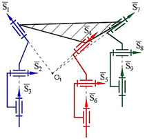
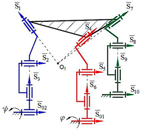
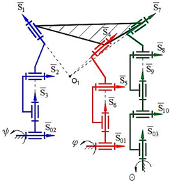
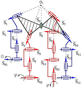
1. Introduction
Structural synthesis is the first step in the design of new types of robot manipulators, mechanisms and structural formulas. New types of robot manipulators and mechanisms have found a wide range of applications in industry, medicine, outer space and other areas. Synthesized robot manipulators differentiate from each other according to their constraints. Nowadays, synthesizing robot manipulators with variable general constraints is an actual issue.
In [
1], formulas for turning the linear movement to arc and vice versa in the mechanism with an angular constraint which is created from six revolute (6R) kinematic pairs, and in [
2], formulas for a new type of spatial mechanism with linear and angular constraints which are created from 4R, 5R and 6R kinematic pairs were discovered. A valuable method concerning general kinematic chains and mechanisms (degree of freedom independent of metric restrictions), in which some chains have plane motions and others spatial motions, was investigated by Boden [
3]. In the year 1966, Harrisberger and Soni [
4] designed a three-dimensional mechanism providing the requirement
for application in industry. Likewise, in [
5], hybrid overconstrained linkages, and in [
6,
7], overconstrained mechanisms and their degrees of freedom (DOF) were investigated. In 1975 Freudenstein and Alizade [
8] published an article: “On the degree of freedom of mechanisms with variable general constraint”. In this investigation, a precise definition of the term “general constraint” and the general DOF formula for the mechanism were given. The results obtained were compared with the results of Boden, the only investigation concerned with such mechanisms, and the meaning of the variable parameters was understood and the formulas were improved. A 3 DOF parallel linkage with geometric constraints and manipulators with a spherical moving platform were designed with patents in [
9,
10]. The spherical center was selected at different points for mobility of the designed manipulators.
From the beginning of the 21st century, robot manipulators and mechanisms have been further developed with fascinating scientific discoveries. Additionally, in [
11], the method of finding the DOF for mechanisms was researched by a new method. Later, a new article: “Structural Synthesis of Parallel Manipulators”, was written by Alizade and Bayram [
12], in 2004. In this methodology, the synthesis of geometrical and kinematic structures of parallel manipulators was fulfilled. Thanks to the analysis of invented manipulators, tables based on new formulas and general methods have been set up and a few examples have been shown. Furthermore, the method of synthesizing and the DOF of the mechanisms were investigated by Phillips [
13]. Kong and Gosselin showed the problem of the type synthesis in the instantaneous motion of legs, and the constraints are described by a screw theory in the article [
14]. Instantaneous motion is also called the twist system of the kinematic chain. In 2006, Alizade, Bayram and Gezgin [
15] described structural synthesis, some new ideas about the creation of platform manipulators, new configurations and structural formulas. Nine new Cartesian platform robot manipulators were designed, and the mobility of the manipulators created in a space of
was examined. Gogu [
16] analyzed the design and structural synthesis of parallel robots with different DOF. He introduced structural mobility analysis of translational parallel robots during his research. Moreover, “Structural Synthesis of Euclidian platforms robot manipulators with variable general constraint” was investigated by Alizade, Can and Gezgin [
17], in 2008. They also designed serial, parallel and serial–parallel platform manipulators by using dyad, torus, universal and spherical kinematics pairs. The new structural formulas of the presented manipulators were considered, developed and explained with 3D models, and an algorithm was prepared to create a new structure. Inspired by studies of structural synthesis, new formulations of parallel manipulators with linear and linear–angular conditions and 14 structural groups operating in a subspace of
were investigated in [
18,
19]. Researchers also introduced new hybrid combinations and a geometric methodology to use in the special case of parallel manipulators. In [
20], the method framework of the type of synthesis of parallel manipulators was studied and existing problems of these issues in distinctive approaches were investigated. In 2015, Hegedüsa, Lib, Schichoc and Schörckerd [
21] published an article: “The theory of bonds II: Closed 6R linkages with maximal genus”. In this investigation, closed linkages with six rotational joints that allow a one-dimensional set of motions were studied. Furthermore, they proved that the genus of the configuration curve of such a linkage is, at most, five and gave a complete classification of the linkages with a configuration curve of the genus of four or five. In the year 1966, Bałchanowski [
22] presented a method of the structural synthesis of spatial or planar parallel mechanisms. Thus, the successive steps in the procedure for generating a structural form of a closed branch, the opening of the branch, the technique of constructing a parallel mechanism from branches with negative and zero DOF and the connection of the drives separated from the branches were described. In 2019, Alizade [
23] published an article: “Structural Synthesis of Robot Manipulators by Using Screw with Variable Pitch”. In this approach, new structural formulas and schemes of kinematic pairs were described for parallel Euclidian platform robot manipulators with fixed and variable general constraints. In addition, 6 DOF Euclidean special docking manipulators of the spacecraft with the same general constraints of each leg of
were given.
In this article, the DOF of dyad compounds established by higher kinematic pairs with is found by using analytical methods. Moreover, structural classification for expressing robot manipulators and their kinematic pairs is depicted in tables. Later, the architectures of the different types of structural groups and kinematic chains with general constraint one are set up. By using angular requirements, the structural synthesis of new first- and second-class robot manipulators with general constraint one is carried out. Finally, the mobility number in the subspace of for the end-effector of robot manipulators is elucidated by structural schemes and physical models.
The use of such robot manipulators is considered more useful in reducing production errors and ensuring reliability. Excess freedom can lead to over-movements, making it difficult to evaluate and control the movement of robot manipulators in certain directions. We also need some overconstrained robot manipulators in medicine that move in the subspaces during surgery. If the movement we need is only the sum of 5 DOF or less than in the system, it would be more useful to build and use an overconstrained robot manipulator for this purpose.
2. Structural Synthesis of Robot Manipulators with General Constraint One
The mobility number of robot manipulators should be provided during structural synthesis. It is obvious that the free solid object in the space has 6 DOF, and the mobility number of the space is . In three-dimensional space, this complex motion corresponds to the combination of rotation and translation movements. The mobility number of the robot manipulator’s executive body in the subspace can be . The geometry of higher kinematic pairs with the maximum DOF of is analytically analyzed for the movement of the executive body of the robot manipulators with the mobility number in the subspace of . The sphere–sphere and sphere–plane kinematic pairs are studied as the object of the research.
Two types of robot manipulators are considered during the synthesis: lower- and higher-class robot manipulators. The lower-class robot manipulators are constructed of single or multiple sets of the second- and third-class structural groups, and the upper-class robot manipulators are constructed of fourth- and higher-class structural groups. During the research, lower-class robot manipulators are investigated. The formulas shown in the literature, Equations (5), (27) and (28) [
7,
18], are used during the structural synthesis of robot manipulators. The number of independent loops
L and number of platform joints
in the kinematic chain are defined by the following formulas:
where
—total number of joint elements on the moving platforms;
—number of moving platforms;
—number of branches between moving platforms;
—total number of legs;
—number of single DOF joints between two platforms;
—sum of hinges, branches and legs.
If robot manipulators have more than one mobile platform, these mobile platforms may be connected to each other by means of kinematic chains which we call branches; the mobile platform of the robot manipulator is connected to the frame (fixed link) by kinematic chains that are generally called legs. Using Equation (1), the number of independent loops can be described as
. Mobility equations of platform robot manipulators are described as follows:
where
—closed loop motion parameter that describes the positions and orientations of the couple in the loop;
—DOF of kinematic pairs;
—number of joints.
The equation for simple structural groups
M = 0, according to Equation (2), can be given as
Assume that each leg with the same number of joints in a structural group consists of only single DOF joints. Knowing that each kinematic pair is a revolute kinematical pair (
), which means they have an axis of rotation, makes it possible to determine the total number of the axes (
) in the structural synthesized robot manipulators by finding the total number of kinematic pairs (
). Thus, the number of kinematic pairs for
can be calculated by using Equation (3). The number of revolute joints placed on each leg and the general constraint for the motion of a rigid body in space
are determined by using the following Equation (4):
Definitions for structural classification applied to robot manipulators given in the literature [
11] are improved as follows:
Class of a structural group is the number of mobile platforms it has.
Type of a structural group is the number of independent loops it has.
Order of a structural group is the number of legs it has.
Structural classifications are listed separately for each robot manipulator shown in the tables.
In our research, a graphical method is applied in the synthesis of the investigated robot manipulators with general constraint one.
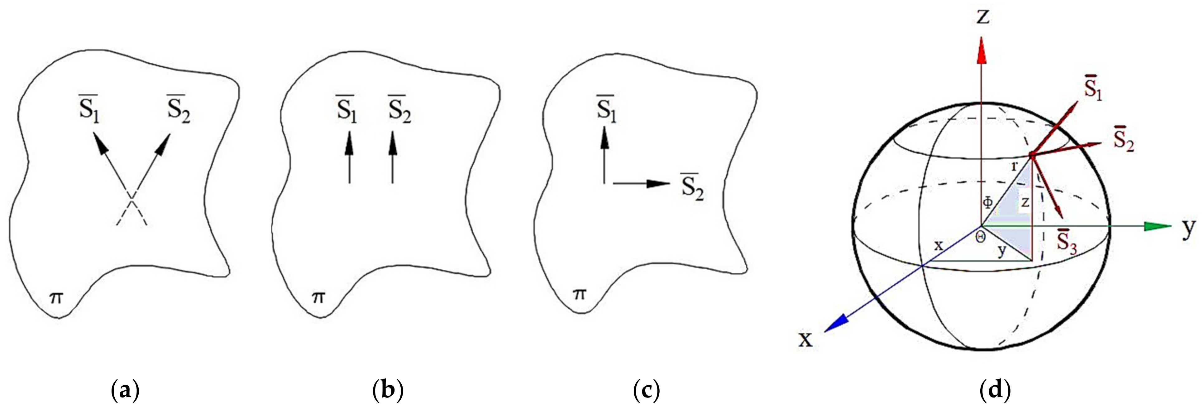
To understand the essence of this method, let us list the following simple and geometric concepts which are known to us from the descriptive geometry. Since the geometric figures we used here are sphere and plane, the method of their graphic representation is shown in
Figure 1.
It is known from descriptive geometry that in a two-dimensional coordinate system for any number of dimensions, a plane (
) is uniquely determined by two distinct but intersecting straight lines (
Figure 1a) and two parallel straight lines (
Figure 1b). Two perpendicular straight lines are considered here to be a special case of “two distinct but intersecting straight lines” (
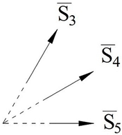
Figure 1c). For a sphere, this determination can be accepted by a combination of three unit vectors (
) intersecting at one point (
Figure 1d). The unit vectors used for the description of the sphere and the plane are denoted by the vectors
in the tables.
3. Determination of the Space Mobility Number and General Constraint for Sphere–Sphere Higher Kinematic Pair
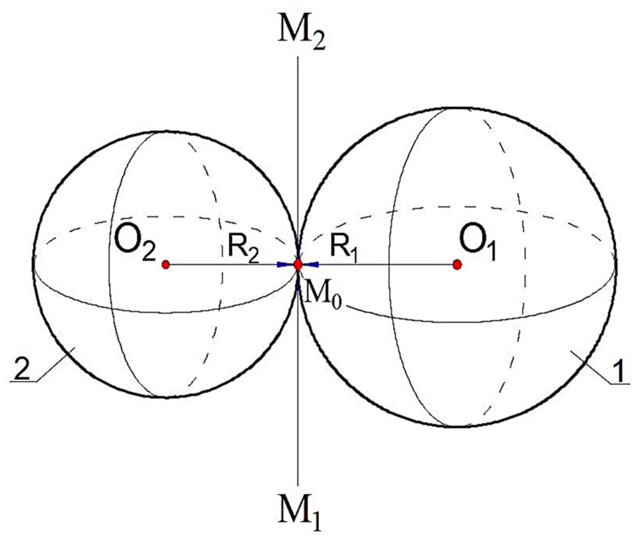
First, let us look at the sphere and sphere kinematic pair (
Figure 2). This kinematic pair is created by causing two spheres to touch each other. It is known that the two spheres are touching each other at only one point. This means that the sphere and sphere dyad has only one constraint
. As a result, the mobility number of the dyad is determined as
. The analytical solution of this problem is explained as follows.
Let us suppose that the centers on the
and
points of the spheres are given with radii
R1 and
R2. These spheres are touching each other at the point of
.
is a straight line passing through the point of
and tangent to both spheres. Moreover, line
defines the position of the kinematic pair in question.
and
consistently show the radius of the first and second spheres. That is why it is possible to write the following equations,
and
. Therefore, it is possible to rise perpendicular to the straight line from the taken point on the
straight line, and according to the known mathematical principle, we can write the next equation
. Therefore,
and
vectors are collinear because they settled on the same straight line
. There is the ratio of
, then
The equation shown above can be written in the following form:
The following equation is for the
R1 radius sphere with a central point of
:
The following equation is for the second
R2 radius sphere with a central point of
:
There are eight parameters according to the equations of tangent spheres (7) and (8), that is, the number of the DOF of these spheres is eight, and after adding a parameter——to this system, the number of the DOF becomes 9. The number of formulas that coordinate the parameters which determine the number of DOF is four (see Equations (5) and (6)). Thus, we find the mobility number of the investigated system by subtracting the number of balanced equations from the number of unknown parameters written for the sphere–sphere kinematic pair. As a result, the space mobility number of the studied system is found as and the general constraint is found as .
At the next stage, the first- and second-class structural synthesis of the higher kinematic pair sphere and sphere (
) transformation is demonstrated together with structural schemes in
Table 1 and
Table 2.
At this point, we can give the following definitions for structural classification:
—vector, ()—spherical expression with the three intersecting non-coplanar vectors;
R—revolute kinematic pair, ()—the written form of the sphere with revolute kinematic pairs;
and —written form of the revolute pairs for spheres with centers of and .
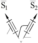
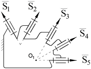
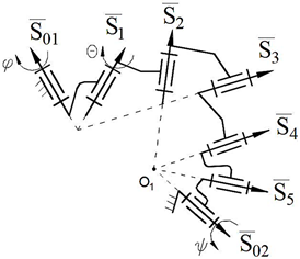
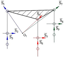
The motion of the spherical pair is provided for the manipulator by using the intersection of each of the three axes of kinematical pairs on one leg, which is denoted as the letter “”, and by attaching to the center point of the first sphere, which is denoted as the letter “”. The axis of the fourth kinematic pair on each leg is connected to the center point of the second sphere by an “” to ensure the absence of a spherical four-bar subchain concentration.
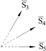
In
Table 1, the first-class structural synthesis of robot manipulators for
is performed in the following sequence:
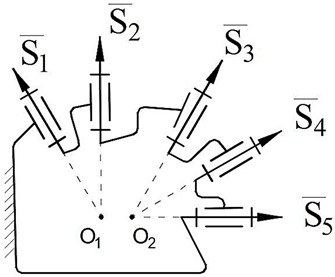
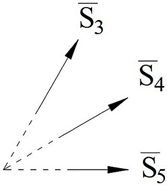
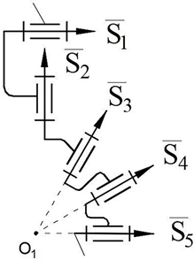
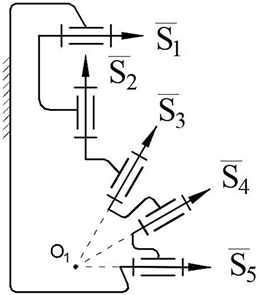
Initially, the description of the sphere with vectors is shown in
Table 1, 1.1. Secondly, revolute pairs of the spheres are obtained by adding revolute kinematic pairs to the vectors (
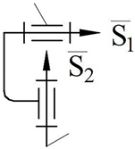
Table 1, 1.2). Thirdly, the
kinematic chain is constructed by connecting the revolute kinematic pairs of the two spheres (
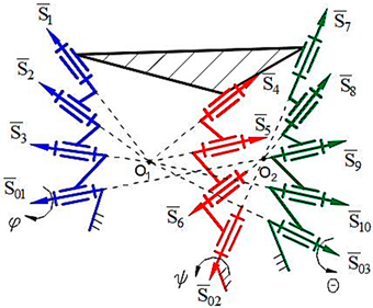
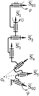
Table 1, 1.3). Then, the first-class structural group from the designed kinematic pair is synthesized, M = 0, λ = 5, d = 1 (
Table 1, 1.4). Afterwards, structural synthesis of the serial robot manipulator is depicted, M = 5, λ = 5, d = 1 (
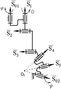
Table 1, 1.5). Finally, the structural scheme of the closed-loop manipulator is shown, M = 2, λ = 5, d = 1 (
Table 1, 1.6). Here, S
01 and S
02 describe actuators for each leg of first-class robot manipulators.
In
Table 2, the first- and second-class structural synthesis of robot manipulators for
is performed in the following sequence:
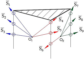
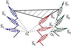
Firstly, the description of the vectors and kinematic chain of the two touching spheres placed on the legs of the platform is shown in
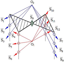
Table 2, 1.1 and 1.2. Then, the first-class structural group, M = 0, λ = 5, d = 1, is synthesized by using the designed kinematic chain (
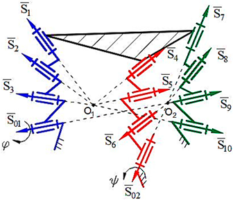
Table 2, 1.3). Later, structures of two kinds of platform-type parallel manipulators are synthesized, M = 2, λ = 5, d = 1 and M = 3, λ = 5, d = 1 (
Table 2, 1.4 and 1.5). All processes in
Table 2, 2.1–2.6, are analogical to those described above.
At the next stage, other types of first- and second-class robot manipulators with given parameters of B = 2,
= 4,
= 1 and L = 3 are synthesized in
Table 2, 2.1–2.6. Here, S
0 shows the hinge (revolute joint) between two platforms and S
01, S
02, S
03 and S
04 express actuators for each leg of second-class robot manipulators.
4. Determination of the Space Mobility Number and General Constraint for Sphere–Plane Higher Kinematic Pair
In the second part of the study, the sphere and plane kinematic pair is considered (
Figure 3). This kinematic pair is created by causing the sphere and plane to touch each other. Obviously, the sphere and plane are touching each other at only one point. In this case, the kinematic couple will have a constraint
. Consequently, the mobility number of the dyad is determined as
. The analytical solution of this mobility number is as follows.
Let us suppose that the given plane is touching the sphere at the point of .
The radius of the given sphere is R and the center of the sphere is located at the point of
. Let us assume the parameter
, and then we can write the following equation:
From the last equation,
,
and
. From here, it appears that the number of the degrees of freedom of the plane is 3 (
). The general equation of a sphere is as follows:
where the center and radius of the sphere are given by
and
R. From here, it appears that the number of the degrees of freedom of the sphere is 4
. Thus, in general, the total number of required independent parameters to depict the plane and sphere is 7
.
According to the equation of the plane, we can show the vector of
is perpendicular to the plane of
, i.e.,
. On the other hand, we can show that the given plane is touching the sphere, i.e.,
, where the given point of
is a known parameter. The given
and
vectors are perpendicular to the same plane, so we can tell that they are parallel to each other. There is the parameter
, then
where
is a known parameter. Therefore, the total number of independent parameters is 8
. Equation (11) create three connections among these parameters. Thus, we find the mobility number of the investigated system by subtracting the number of balanced equations from the number of unknown parameters written for sphere–plane kinematic pair. As a result, the space mobility number of the studied system is found as
and the general constraint is found as
.
At the next stage, the first- and second-class structural synthesis of the higher kinematic pair sphere and plane (
) transformation is demonstrated together with structural schemes in
Table 3 and
Table 4.
At this point, we can give the following definitions for structural classification:
, , —the signs of parallel, perpendicular and intersecting vectors of the plane;
, , —the written forms of the parallel, perpendicular and intersecting vectors of the plane with revolute kinematic pairs;
and —written forms of the revolute pairs for spheres with centers of and .
In
Table 3, first-class structural synthesis for
is performed in the following sequence:
Firstly, the description of the plane with parallel vectors is shown in
Table 3, 1.1. Then, the description of the sphere is depicted in
Table 3, 1.2. Revolute pairs of the spheres and planes are obtained by adding revolute kinematic pairs to the given vectors (
Table 3, 1.3 and 1.4). Furthermore, the
kinematic chain is constructed by connecting the revolute kinematic pairs of the sphere and plane (
Table 3, 1.5). Then, the first-class structural group from the designed kinematic pair is synthesized, M = 0, λ = 5, d = 1 (
Table 3, 1.6). Afterwards, structural synthesis of serial robot manipulators is presented, M = 5, λ = 5, d = 1 (
Table 3, 1.7). Finally, the structural scheme of the closed-loop robot manipulator is shown, M = 2, λ = 5, d = 1 (
Table 3, 1.8). In the second part, continuously, expression of perpendicular vectors of the plane is represented (
Table 3, 2.1). The next processes are analogical for
. In the third part, the description of intersection vectors of the plane is presented (
Table 3, 3.1). The next processes are also analogical for
. Here, S
01 and S
02 describe actuators for each leg of first-class robot manipulators.
In
Table 4, first- and second-class structural synthesis for
is performed in the following sequence:
Firstly, the description of the vectors and kinematic chain of the touching sphere and plane which are placed on the legs of the platform is shown in
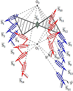
Table 4, 1.1 and 1.2. Secondly, the first-class structural group, M = 0, λ = 5, d = 1,
= 10, is synthesized by using the designed kinematic chain (
Table 4, 1.3). Later, structures of two kinds of platform-type parallel manipulators are synthesized, M = 2, λ = 5, d = 1,
= 12 and M = 3, λ = 5, d = 1,
= 13 (
Table 4, 1.4 and 1.5). All processes in
Table 4, 2.1–2.6 are analogical to those described above.
At the next stage, another type of second-class robot manipulator with given parameters of B = 2,
= 4,
= 1 and L = 3 is synthesized in
Table 4, 2.1–2.6. Continuously, we apply the same method for structurally synthesized robot manipulators in
Table 4, 2. Here, S
0 is showing the hinge (revolute joint) between two platforms and S
01, S
02, S
03 and S
04 express actuators for each leg of second-class robot manipulators.
In addition, the method of adding S0, S01, S02 and S03—revolute kinematic pairs—into the structure of platform-type robot manipulators for SF is presented. Note that over three revolute kinematic pairs cannot be connected to the same center on one leg of the platform-type robot manipulator. —functional dependence is shown for the closed-loop robot manipulator. Here, represents the constant parameters of robot manipulators.
5. Physical and Computer Models of Designed Robot Manipulators with General Constraint One
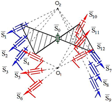
Computer models of synthesized robot manipulators with general constraint one were created using SolidWorks software. Physical models were obtained from 3D printing by providing the assembly of the manufactured elements. Furthermore, provided axioms were obtained from the result of experimental processes. The physical and computer models of the synthesized lower-class robot manipulators with general constraint one are shown in
Figure 4 for sphere–sphere and
Figure 5 for sphere–plane.
The obtained results can be given as the following axioms as the decisions of the structural synthesized robot manipulators with general constraint one:
Axiom 1: The distance between the intersection point of the joint axes
of the robot manipulators which is created by the transformation of the geometrical figure
, and
remains constant during its motion (
Figure 4).
Axiom 2: The motion along the axis passing through the contact surfaces and centers of geometric figures is limited. This determines the number of constraints of the robot manipulator and the spatial mobility of its output element .
Axiom 3: To ensure the motion of platform-type multi-loop contour robot manipulators, the axes passing through the center of the revolute joints that make it up must be on the axis that passes through the centers of the geometric figures (
) (
Figure 4 and
Figure 5).
Axiom 4: In order to ensure the motion of platform-type multi-loop contour robot manipulators, the links attached to the ground must be placed on different coordinate axes () in different offsets, and the length of the links should not be equal among each other.
Axiom 5: The kinematic pairs of platform-type multi-loop contour robot manipulators located on the singular axes cannot be taken as a driver joint (
Figure 4. Axis 4, 8, 12., and
Figure 5. Axis 1, 5, 9). Thus, if this happens, the robot manipulator collapses during the motion.
Axiom 6: The largest revolute motion of a platform-type multi-contour robot manipulator is obtained along the intermediate axis of the spherical subchain (
Figure 4. Axis 2, 6, 10., and
Figure 5. Axis 3, 7, 11).
