Review

Femtosecond Laser-Assisted Electron Scattering for Ultrafast Dynamics of Atoms and Molecules

Department of Chemistry, School of Science, The University of Tokyo, Tokyo 113-0033, Japan
*
Author to whom correspondence should be addressed.
Atoms 2019, 7(3), 85; https://doi.org/10.3390/atoms7030085
Submission received: 7 July 2019 / Revised: 17 August 2019 / Accepted: 23 August 2019 / Published: 2 September 2019
(This article belongs to the Special Issue Electron Scattering in Intense Laser Fields)

Abstract

:
The recent progress in experimental studies of laser-assisted electron scattering (LAES) induced by ultrashort intense laser fields is reviewed. After a brief survey of the theoretical backgrounds of the LAES process and earlier LAES experiments started in the 1970s, new concepts of optical gating and optical streaking for the LAES processes, which can be realized by LAES experiments using ultrashort intense laser pulses, are discussed. A new experimental setup designed for measurements of LAES induced by ultrashort intense laser fields is described. The experimental results of the energy spectra, angular distributions, and laser polarization dependence of the LAES signals are presented with the results of the numerical simulations. A light-dressing effect that appeared in the recorded LAES signals is also shown with the results of the numerical calculations. In addition, as applications of the LAES process, laser-assisted electron diffraction and THz-wave-assisted electron diffraction, both of which have been developed for the determination of instantaneous geometrical structure of molecules, are introduced.

1. Introduction

Laser-assisted electron scattering (LAES), which is also known as free–free transition (FFT), consists of electron-atom scattering under the presence of laser fields, resulting in the appearance of laser-induced sidebands with the interval of the photon energy (ħω) in the energy spectra of scattered electrons (i.e., Ef = Ei + nħω, where Ei and Ef are the kinetic energies of the incident electron and the scattered electron, respectively; ħ is the Plank constant; ω is the angular frequency of the laser field; and n is an integer number). In some cases, the energy gain process (n > 0) and the energy loss (n < 0) process are separately called “inverse bremsstrahlung” and “stimulated bremsstrahlung”, respectively, using the technical term of bremsstrahlung, which is the light emission induced by a sudden acceleration of incident electrons by an atomic potential. LAES processes can be regarded as a three-body collision process, where not only the electron-atom interaction, but also the laser-electron interaction and the laser-atom interaction take part in the scattering process. Due to the interplay between these interactions, energy-resolved angular distributions of scattered electrons exhibit complex and intriguing structures. In addition to the interest in collision physics, the LAES process is an important elementary process included in a wide variety of phenomena induced by laser fields such as electron heating in laser plasma [1], scattering of recolliding photoelectrons in intense laser fields [2,3], emission of high-energy photoelectrons from dense gas media in intense laser fields [4], and the conductance properties of doped semiconductors interacting with laser fields [5].
Experimental studies of LAES processes started in the 1970s [6,7,8], and for more than three decades, continuous CO2 lasers and pulsed CO2 lasers with a temporal duration of microseconds have been employed in experiments. The main theme of these studies was the investigation of the collision process itself, and a validity of theories were proposed, whose validities were examined using the experimental data. In 2010, the first observation of LAES induced by a femtosecond laser field was reported by our group, and the idea of ultrafast optical gating of scattering processes was introduced [9]. Furthermore, it was shown that light-dressed processes of atoms and molecules could be investigated by LAES experiments using intense ultrashort laser pulses [10], which had not been explored before in LAES experiments performed using CO2 lasers. Recently, we proposed the idea of ultrafast streaking of scattering processes [11], where the collision time can be determined from the energy and the scattering angle of a scattered electron, so that a time-resolved differential cross section can be obtained without a scanning pump–probe time delay. The concepts of the optical gating and the optical streaking of scattering processes can be applied to ultrafast time-resolved electron diffraction by which movies of chemical reaction processes can be made. In this review, we focus on our recent progress in the investigation of the LAES processes induced in a femtosecond laser field. Earlier studies on the LAES processes can be seen in the comprehensive review articles [6,7,8].
After briefly introducing the theoretical framework of the LAES processes (Section 2) and early LAES experiments (Section 3), we describe the concepts of optical gating and optical streaking by LAES processes in Section 4. In Section 5, we describe an apparatus for measuring LAES processes induced by femtosecond laser pulses in detail. In Section 6, we show some examples of femtosecond LAES measurements for atomic targets and their applications to the investigation of light-dressed states and the assignment of collision times. In Section 7, we describe an application of LAES processes to ultrafast gas electron diffraction, and, in Section 8, we discuss future directions of femtosecond LAES experiments.

2. Theory of Laser-Assisted Electron Scattering (LAES)

The theoretical framework of the LAES process was proposed first by Bunkin and Fedorov in 1966 [12]. Under the first Born approximation of the scattering process between a target atom and an electron expressed as an eigenfunction of a free electron in an electromagnetic field (i.e., a Gordon–Volkov wavefunction [13,14]), they derived the differential cross section for net n-photon absorption, dσ(n)BFA/dΩ, as
d σ BFA ( n ) d Ω = | p f | | p i | J n 2 ( α 0 s ) d σ FBA d Ω ,
where Jn(x) is the n-th order Bessel function of the first kind; pi and pf are the initial and final electron momenta, respectively; dσFBA/dΩ is a differential cross section of elastic scattering without laser fields derived by the first Born approximation; s is a scattering vector defined by (pipf)/ħ; and α0 is defined as
α 0 = e F m e ω 2 ,
where e is unit charge; me is mass of an electron; and F is an electric amplitude vector of the laser field. The absolute value of α0, |α0|, corresponds to the quiver radius (i.e., the amplitude of the classical motion of an electron in the electromagnetic field). In the Bunkin–Fedorov approximation (BFA), the interaction between an atom and a laser field is neglected, and the electron-atom interaction is treated within the first Born approximation, which is a good approximation for the forward scattering of high-energy electrons, and the non-perturbative interaction between an electron and a laser field is explicitly treated by using the Gordon–Volkov wavefunctions for the incident and scattered electrons. Equation (1) shows that the differential cross section for the n = 0 LAES process is also modified by the laser field. Because the scattered electrons of this n = 0 LAES process have an overlap in the kinetic energy with the electrons scattered by an elastic scattering process without laser fields, the two different scattering processes fulfilling Ei = Ef are referred to as “n = 0 scattering” regardless of their origins throughout the present paper.
In 1973, Kroll and Watson derived the differential cross section of a LAES process by taking into account the non-perturbative interaction between an electron and an atom [15]. In the Kroll–Watson approximation (KWA), the formula of the differential cross section for the net n-photon absorption, dσ(n)BFA/dΩ, takes a similar form to Equation (1), and is written as
d σ KWA ( n ) d Ω = | p f | | p i | J n 2 ( α 0 s ) d σ el ( E ˜ i ; s ) d Ω ,
where dσel(i; s)/dΩ is the differential cross section of the elastic electron scattering; p ˜ f = p ˜ i s p ˜ i , occurring without laser fields with an incident electron whose initial momentum, p ˜ i , and the initial kinetic energy, i, are defined as p ˜ i = p i + n m e ω α 0 / ( α 0 s ) and E ˜ i = | p ˜ i | 2 / ( 2 m e ) , respectively. Equation (3) means that the differential cross section of the LAES process is calculated using dσel (i; s)/dΩ), determined by the conventional scattering experiments performed without a laser field, which can be found in a NIST data base [16]. The Kroll–Watson formula can also be applied to slow-electron scattering and backward scattering. However, the formation of light-dressed states of target atoms could not be described by the Kroll–Watson formula because the interaction between an atom and a laser field is neglected.
Mittleman et al. [17,18,19,20] developed a theoretical framework for an electron-atom scattering in the presence of a laser field whose frequency is near resonant to the atomic transition. Zon [21,22] proposed a simple and convenient model by describing the laser-atom interaction as the polarization of electron clouds of target atoms induced by the off-resonant laser fields. Later, Byron et al. [23,24] studied the effect of the formation of light-dressed atoms by treating the laser-atom interaction by a first-order time-dependent perturbation theory and the electron-atom interaction by the first Born approximation. Non-perturbative interactions between laser fields and atoms in high-energy electron-atom scattering processes can be treated in the Born–Floquet theory proposed by Faisal [25], or in the non-Hermitian Born–Floquet theory developed by Dörr et al. [26], while R-matrix Floquet theory [27,28], close-coupling Floquet theory [29], and R-matrix with time-dependence theory [30] are applicable to low-energy scattering processes, where the non-perturbative electron-atom interaction is included in addition to the non-perturbative laser-atom interaction. Other theoretical methods to investigate LAES processes have also been proposed on the basis of a variety of models and approximations as reviewed in [8].

3. Early LAES Experiments

Experimental studies of LAES processes started in 1970s by using cw- and pulsed-CO2 lasers where the wavelength (λ) is λ = 10.6 μm. In 1976, Andrick and Langhans reported the first measurement of LAES [31] and performed an electron-argon scattering experiment with the collision energy of 11.55 eV under the presence of a cw-CO2 laser field with the intensity (I) of I = 6 × 10⁴ W/cm2, and recorded an energy spectrum of electrons at the scattering angle (θ) of θ = 160°. In the energy spectrum, weak sidebands attached to elastic scattering signals appeared at the energy-gain and energy-loss of 117 meV, which corresponds to the photon energy of CO2 laser light. The relative intensity of the sidebands was around 4 × 10⁻⁴ with respect to the elastic scattering signal. They also investigated the dependence of the LAES processes on the collision energy [32]. When the collision energy is in near-resonance with the temporal formation of a negative ion of a target atom, the energy dependence of the differential cross section of the LAES processes showed multiple resonance structures whose shapes were strongly dependent on the scattering angle and the laser polarization direction. In 1978, this phenomenon was observed in the electron-argon scattering in a cw-CO2 laser field [33]. The resonance structures in LAES have been intensively investigated for target atoms of helium [34], neon [35], and argon [33,35].
In 1977, Weingartshofer et al. reported a LAES measurement with a pulsed-CO2 laser [36]. They performed an electron-argon scattering experiment with the collision energy of 11 eV in an intense CO2 laser field (I = 109 W/cm2) with the pulse duration (Δt) of 2 μs. In an energy spectrum of electrons scattered at θ = 153°, they observed multiphoton LAES signals at the energy shift (ΔE = EfEi) of nħω (n = ±1, ±2, ±3), where ħω is the photon energy of a CO2 laser (117 meV). Their group investigated dependences of the LAES processes on the kinetic energy of the incident electrons, the scattering angle, the laser field intensity, and the laser polarization direction for target atoms of helium [37,38,39,40,41,42] and argon [36,43,44,45,46,47] as well as for target molecules such as H2 [43] and CO2 [48].
When an electron is scattered inelastically by a target atom in a laser field, the energy shift of the scattered electron can be ΔE = −Eex + nħω, where Eex is the energy required for the excitation of the target atom to its excited state. This process is called inelastic free–free transition (IFFT) or laser-assisted inelastic electron scattering (LAIES). In particular, when the kinetic energies of incident electrons are just below the excitation energy of the target atoms, kinetic energy modulation of the incident electrons induced by the irradiation of laser fields opens electron impact excitation channels, which could not be achieved without laser fields. The first observation of this process, called simultaneous electron-photon excitation (SEPE), was reported by Mason and Newell [49]. They measured metastable helium atoms in the 23S state generated through the collision between the ground state He atoms and the incident electrons whose kinetic energy is below the threshold of the electronic excitation, 19.817 eV, under the presence of a CO2 laser field. The SEPE processes induced by a CO2 laser field (λ = 10.6 μm) have been reported for target atoms of helium [49,50,51,52,53,54], neon [51], and argon [51], and those induced by a Nd:YAG laser field (λ = 1.064 μm) have been reported for helium target atoms [55]. From these SEPE measurements, we derived the total cross sections of the SEPE processes, and therefore, in order to obtain differential cross sections, we needed to measure the angle-resolved energy spectra of electrons inelastically scattered by the target atoms. Wallbank et al. reported on the angle-resolved energy spectra of electrons that are scattered inelastically by helium atoms in CO2 laser fields [56,57].

4. Optical Gating and Optical Streaking of Electron Scattering Signals

The idea of the optical gating of scattering events by LAES processes was proposed in 2010 [9]. In the LAES processes,
Ef = Ei + nħω,
is satisfied, and the energy-shifted electrons are generated only when the scattering occurs under the presence of a laser field. Therefore, the LAES process can be regarded as a cross-correlation between the laser beam and the electron beam, and the information of target atoms and molecules during the laser pulse duration can be extracted from the angular distributions of the energy-shifted electrons generated through the LAES processes. As the temporal resolution of this scheme is determined solely by the laser pulse duration, a temporal resolution better than 10 fs can be achieved in a straightforward manner, which exhibits a marked contrast to the conventional time-resolved pulsed-electron scattering scheme where ultrashort electron pulses are employed to achieve high temporal resolutions. By taking advantage of the ultrashort optical gating, we proposed a method to determine the instantaneous geometrical structure of molecules by laser-assisted electron diffraction (LAED) [9] and reported on the experimental demonstration of the LAED for CCl4 in 2014 [58]. Details of the LAED method will be discussed in Section 7.1.
The optical gating method can also be applied to the investigation of ultrafast responses of electrons in target atoms and molecules because the kinetic energy of the scattered electrons can vary when electrons in the target oscillate periodically [10]. Indeed, the ultrafast responses of the electrons in the target are mapped into the energy distribution of the scattered electrons as discrete Fourier components, and the angular distribution of each Fourier component carries information on the spatial distribution of the electrons in the target, as discussed in Section 6.2.
On the other hand, through the optical streaking scheme, the temporal resolution of the sub-optical cycle can be achieved. In highly-nonlinear laser-induced processes such as laser-assisted ionization [59,60], high-order harmonic generation [61], and laser-induced electron diffraction [62], the temporal resolution in the attosecond time domain can be achieved even when femtosecond laser pulses are employed. This is because nonlinear processes are strongly dependent on the instantaneous laser electric field. In 2018, we showed that the optical streaking scheme could be introduced in the LAES measurements as long as the laser field is well-characterized [11].
In order to theoretically describe the optical streaking scheme where the LAES processes are induced by an ultrabroadband electromagnetic field of a single-cycle or few-cycle laser pulse, we introduced a modified Kroll–Watson formula in 2018 [11]. In the modified Kroll–Watson theory, the differential cross section, dσMKWA/dEfdΩ, is given by
d σ MKWA d E f d Ω = | p f | | p i | lim T 1 2 π T | T / 2 T / 2 d t e i Δ ( k i , k f , t ) f k ˜ i , k ˜ f el ( t ) | 2 ,
where f k ˜ i , k ˜ f el ( t ) is a scattering amplitude of the elastic scattering from k ˜ i to k ˜ f in the absence of electromagnetic fields, where k ˜ i and k ˜ f are defined as
k ˜ i , f = k i , f + e A ( t ) ,
and Δ ( k i , k f , t ) is defined using a vector potential of the electromagnetic field, A(t), as
Δ ( k i , k f , t ) = E f E i t e m e t d τ s A ( τ ) .
In contrast to LAES induced by a monochromatic electromagnetic field, where ΔE = EfEi takes discrete values of nħω, LAES processes induced by an ultrabroadband electromagnetic field allow continuous ΔE values. In the derivation of Equation (5), the low-frequency approximation (i.e., Ei >> ħω) is employed. Numerical simulations of LAES signals can be conducted using Equation (5). Furthermore, by applying the stationary phase approximation to Equation (5), a semi-classical formula of dσMKWA/dΩ is given as
d σ MKWA d E f d Ω = | p f | | p i | lim T 1 2 π T | j e i Δ ( k i , k f , t c ( j ) ) 2 π i m e e | s F ( t c ( j ) ) | f k ˜ i , k ˜ f el ( t c ( j ) ) | 2 ,
where t c ( j ) is the collision time when a projectile electron collides with a target. Equation (8) is derived using the stationary phase approximation that LAES processes fulfill with the following relationship,
Δ E = [ m e e A ( t c ( j ) ) ] s ,
where A(t) = |A(t)| and s is the component of s along the direction of A(t). The temporal shape of A(t) can be determined experimentally by an established method for laser-pulse characterization, and therefore, tc can be determined from the measurements of s and ΔE in LAES processes, which means that the LAES signals are optically streaked by the external light field. Because sub-cycle temporal resolution can be achieved by this optical streaking scheme, LAES processes induced by a single-cycle (or few-cycle) pulse in the THz region and the mid-infrared wavelength region yield the temporal resolution of sub-10 fs and sub-100 as, respectively. By adopting the streaking scheme, we can extract time-resolved information without scanning the temporal delay between pump and probe pulses. This means that the streaking scheme is free from the influence of the drift in the electron beam currents as well as from that in the laser intensities during the measurements.

5. Experimental Setup for Recording Femtosecond-LAES Signals

Details of the experimental setup have been described in [63]. Figure 1 shows the schematic of our setup for the femtosecond-LAES experiments. The apparatus consists of a femtosecond laser system, an electron beam source, a sample gas nozzle, a toroidal-type electron energy analyzer, and an imaging detector. Scattered electrons generated by the collisions of the three beams (i.e., the electron beam, the atom beam, and the laser beam) are introduced into the electron energy analyzer and are detected by the imaging detector.
By taking the leading term of the Bessel functions in Equation (1) or Equation (3), intensities of the LAES signals in BFA and KWA become approximately proportional to Δt(λ4I)|n|. This means that the signal intensities per laser-shot for the n = ±1 transitions in LAES should decrease by a factor of 1 × 10⁻⁸ when the laser field conditions change from “Δt = 3 μs, λ = 10.6 μm, I = 4 × 10⁸ W/cm2” to “Δt = 200 fs, λ = 800 nm, I = 1.8 × 10¹² W/cm2”, which correspond to the conditions employed in the most recent conventional LAES experiment with CO2 laser [42] and our first femtosecond-LAES experiment [9], respectively. Therefore, a drastic improvement in the detection efficiency is necessary for the measurement of LAES signals in ultrashort intense laser fields. Furthermore, due to the limited spatial overlap and the velocity mismatch between the electron pulse and the femtosecond laser pulse [64] when a pulsed 1 keV electron beam intersects with a sample gas beam of ~1 mm diameter and a 200 fs laser pulse, the fraction of scattering events in the laser field is estimated to be as small as 0.4% and the majority of the scattering events (99.6%) are those occurring in the absence of the laser fields. Thus, it is difficult to discriminate the femtosecond-LAES signals in the energy spectra of the scattered electrons from the neighboring huge peak of the n = 0 scattering signals. Moreover, intensities of the LAES signals is in general in the same order of magnitude as those of noise signals originating from stray photons, photoelectrons, photoions, and metastable neutral atoms generated by the irradiation of intense near-infrared laser pulses. In order to overcome these experimental difficulties, the following three components were introduced into our LAES apparatus: (i) an electron beam source with a photocathode-type pulsed electron gun; (ii) a high repetition-rate and high-power Ti:sapphire laser system; and (iii) a toroidal-type electron energy analyzer equipped with a two-dimensional detector.
The electron pulses were generated from the photocathode-type pulsed electron gun by the irradiation of the photocathode with UV laser pulses, which are the third harmonics of 800 nm light split from the main 800 nm pulses before a pulse compressor of the laser system. The synchronization between the electron pulse and the intense IR laser pulse was achieved by the adjustment of the optical delay between the UV laser pulse and the intense IR laser pulse. The pulse duration of the electron pulses were determined to be ~50 ps by the shadow graph method [63]. Huge background signals originating from elastic scattering without laser fields can be suppressed by using these ultrashort incident electron pulses. The generated monochromatic electron pulse of 1 keV kinetic energy collides with a Xe gas in a near-infrared intense laser field (Δt = 200 fs, λ = 800 nm, I = 1.8 × 10¹² W/cm2) at the scattering point in the vacuum chamber. The scattered electrons were introduced into the toroidal-type electron energy analyzer through a 0.8 mm slit. Simultaneous measurements of the angular and energy distributions were achieved by the toroidal-type electron energy analyzer [65], and these distributions were obtained as a two-dimensional image on a MCP/Phosphor detector coupled with a CCD camera. On the detector plane, an angular distribution of isoenergetic electrons formed an arcuate pattern as shown in Figure 1. The signals of scattered electrons were discriminated from the noise signals by counting the number of bright spots of electron signals appearing on the CCD images within a time window of one second. Significant improvement in the count rate of the LAES signals was achieved by a 5 kHz data acquisition with a high repetition-rate and high power Ti:sapphire laser system. The number of incident electrons per shot was made as small as possible, by which the energy broadening induced by the space charge effect was minimized, and a typical count rate of the detection of electrons including those originating from the elastic scattering was around 10 cps. The energy resolution of the total detection system was around 0.7 eV, which is sufficiently smaller than the photon energy of the laser light (1.56 eV).

6. Femtosecond LAES Experiments

6.1. Measurements of Femtosecond-LAES Singals

In 2010, we succeeded in recording the LAES signals induced by femtosecond laser pulses, where 1 keV electrons were scattered by Xe atoms in a femtosecond intense laser field (Δt = 200 fs, λ = 800 nm, and I = 1.8 × 10¹² W/cm2) [9]. Figure 2 shows the raw images of the scattered electrons recorded in the femtosecond-LAES experiments. The net exposure time was around 83 h for each image. Figure 2a shows the electron scattering signals obtained when laser pulses were introduced at the timing of the electron scattering by Xe atoms. The laser polarization was set as “vertical” (i.e., perpendicular to the electron beam axis). The intense signals that formed an arcuate line seen at the central area in Figure 2a is n = 0 scattering signals, and no other features could be recognized in Figure 2a. Figure 2b is an amplified image of Figure 2a, which was obtained after adjusting the range of the signal intensity so that the weak LAES signals became visible. In Figure 2b, weak arcuate lines indicated by the white arrows can be seen on both sides of the central arcuate line. On the other hand, such structures could not be seen in the background signals (Figure 2c), which were obtained when the temporal delay of the electron pulse with respect to the laser pulse was set to be +100 ps.
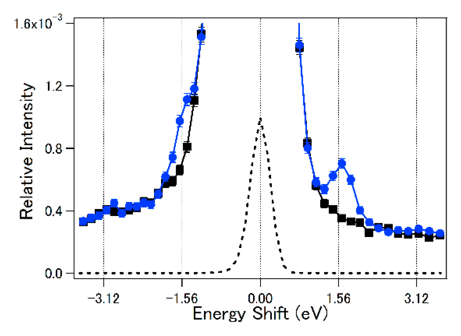
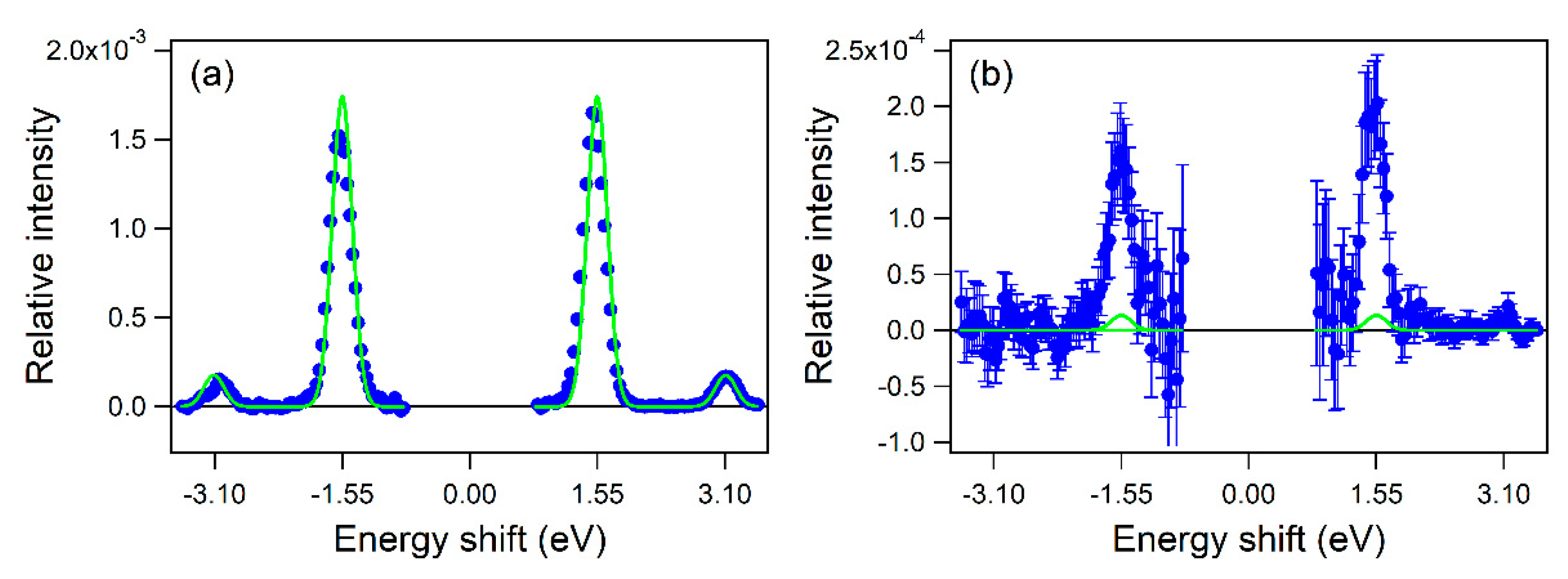
The observed small difference between Figure 2b,c becomes clear in the electron energy spectra, which were obtained through the integration of the signal of each pixel over the scattering angles along the arcuate isoenergetic coordinate. In the integration, the signals in the region of y > 105 pixels in Figure 2 were excluded from the analysis because the contributions of the stray electrons were significantly large in this region. The blue filled circles and the black filed squares in Figure 3 show the energy spectra obtained from Figure 2b,c, respectively. Unambiguous increases in the signal intensity appear at the kinetic energy shifts of ± ħω (i.e., ±1.56 eV) in Figure 3 (blue filled circles). This is clear experimental evidence of the n = ± 1 transitions in the LAES process.
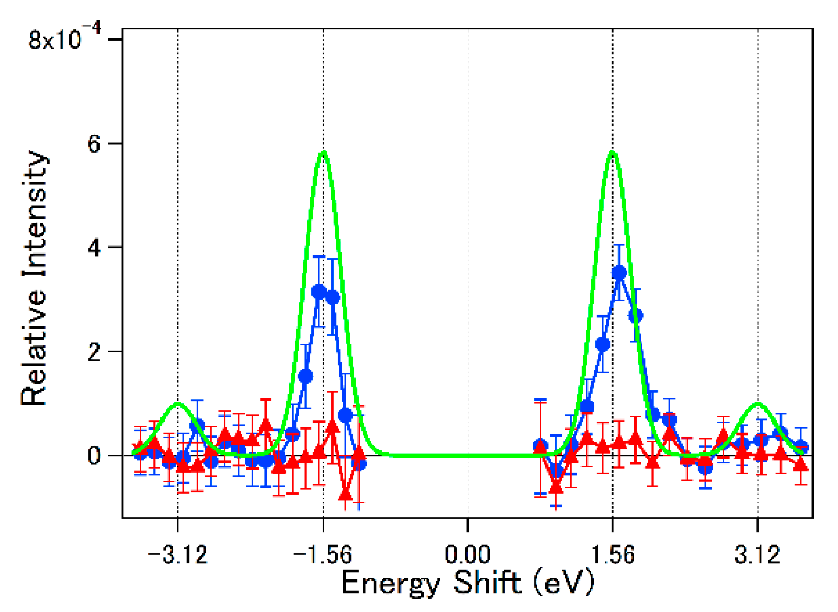
The blue filled circles in Figure 4 represent the LAES signals obtained by subtracting the background signals from the scattering signals obtained with the laser field in Figure 3. Both of the signals at the energies of ± ħω can be recognized as distinct peaks, and the intensities of these peaks are around 3 × 10⁻⁴ relative to the central n = 0 scattering peak.
In order to confirm our assignment, we estimated the relative intensities of the LAES signals by a numerical simulation based on Equation (3). In the simulation of the observed LAES signals, denoted by w(n)(Ei; s), the differential cross section in Equation (3) was averaged over the spatiotemporal distribution of the three beams (i.e., the electron beam, the laser beam, and the atomic beam). Because the dσel(i; s)/dΩ ≈ dσel(Ei; s)/dΩ is considered to be independent of the laser field, the w(n)(Ei; s), can be factorized into two parts:
w ( n ) ( E i ; s ) = G n ( E i ; s ) d σ el ( E ˜ i ; s ) d Ω ,
where
G n ( E i ; s ) = | p f | | p i | d r ρ ( r ) d t j ( r , t ) J n 2 ( α 0 ( r , t ) s ) .
In Equation (11), ρ(r) is a density of the sample atoms and j(r, t) is an electron flux density. The spatiotemporal distributions of ρ(r) and j(r, t) can be determined experimentally [63]. The vectorial quiver radius, α0(r, t), becomes a function of r and t because of the spatiotemporal distribution of F, and can also be derived experimentally, as described in [63] by using the laser field parameters such as the pulse energy, the temporal shape of the pulse envelope, and the spatial profile at the scattering point. Therefore, w(n)(Ei; s) in Equation (10) can be calculated using Gn(Ei; s) obtained from Equation (11) using the differential cross section (dσel(Ei; s)/dΩ) in the NIST database [16]. The results of the simulation were plotted with a green solid line in Figure 4. The calculated LAES signal intensities relative to the n = 0 scattering signal intensities showed good agreement with the experimental results.
When the laser polarization vector is set to be “horizontal” (i.e., parallel to the direction of the incident electron beam), the factor of α0·s in Equation (2) becomes close to zero because the polarization vector is nearly perpendicular to the scattering vector, s, for the forward scattering of the high-energy electrons. Consequently, the LAES signal intensities are suppressed significantly, except for the n = 0 scattering signal intensity. This polarization dependence provides further verification of our measurements of the LAES signals of n = ±1. In Figure 4, an energy spectrum with the horizontally polarized laser field is plotted with red filled triangles. In contrast to the corresponding spectrum obtained using the vertically polarized laser field, no distinguishable peaks are observed. This is consistent with the corresponding numerical calculation, showing that relative intensities for the n = ±1 transitions were nearly zero (7 × 10⁻⁶).
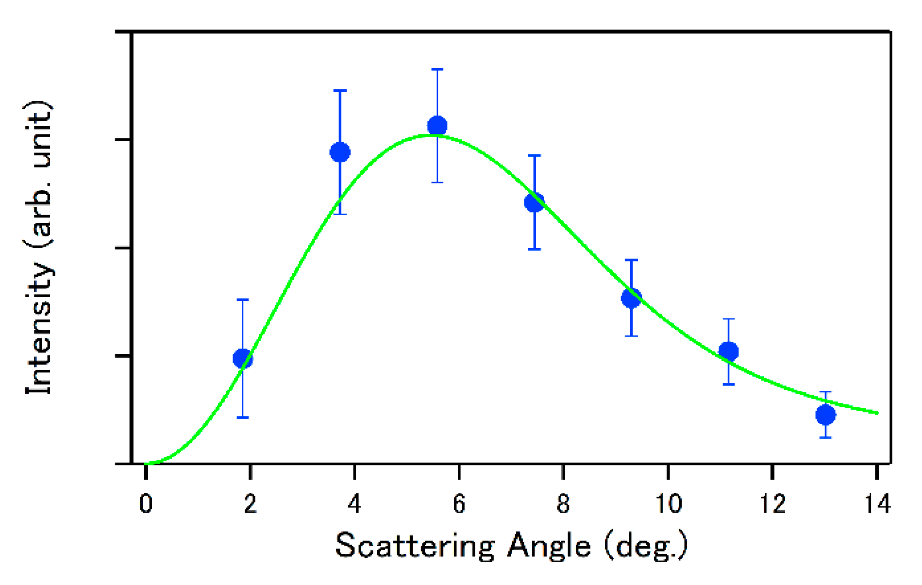
The blue filled circles in Figure 5 show the angular distribution of the background-subtracted LAES signals for the n = +1 transition recorded using the vertically polarized laser field. The green solid line shows the results of the numerical calculations with KWA. The calculated angular distribution is in good agreement with the experimental angular distribution. The angular distribution of the n = −1 transition is basically the same as that of the n = +1 transition, and also shows agreement with the results of the numerical calculations.
After the first observation of the LAES signals induced by 200 fs laser pulses [9], we report on the LAES experiments with laser pulses whose durations were 50 fs in 2011 [63], 520 fs in 2014 [58], 970 fs in 2015 [10], and 100 fs in 2017 [66]. In 2011, deHarak et al. [67] reported the results of the measurements of the LAES processes occurring in the laser field whose intensity is of the order of 109 W/cm2 generated using the Nd:YAG laser (Δt = 6 ns, λ = 1064 nm). They also investigated the dependences of the LAES processes on the laser polarization [68,69] and target atomic species [70], and determined the angular distribution of the scattered electrons [71]. More recently, they reported preliminary results of laser-assisted inelastic electron-argon scattering induced by near-infrared nanosecond laser pulses [72].

6.2. Light-Dressing Effect in Laser-Assisted Elastic Electron Scattering

As discussed in Section 2, the Kroll–Watson formula of the differential cross section of a LAES process with n-photon absorption was derived under the assumptions that both of “the laser-electron interaction” and “the electron-atom interaction” are treated in a non-perturbative manner while “the laser-atom interaction” is neglected. However, when the laser field intensity becomes stronger, the laser-atom interaction cannot be neglected, and the spatiotemporal evolution of the electron distribution within the target atom influences the energy distribution and the angular distribution of the LAES signals. In 1984, Byron and Joachain [23] calculated the differential cross section of LAES of a light-dressed hydrogen atom by considering the laser-atom interaction using the first-order perturbation theory, and predicted that an intense peak structure would appear at the small scattering angles of the LAES processes of n = ±1. Their study showed that the small-angle LAES signals carries valuable information on the electron density distribution in the target atom influenced by an external laser field. In spite of this theoretical prediction, the light-dressing effect in LAES has not been identified experimentally for more than 30 years because the light-field intensities (<109 W/cm2) in the early LAES experiments, where mid-infrared cw- or pulsed-CO2 lasers that were employed [6,7,8], were not sufficiently high. In 2015, we reported the observation of LAES signals appearing through this light-dressing effect by measuring the scattering of 1 keV electrons by Xe in an intense laser field (λ = 800 nm, I = 1.5 × 10¹² W/cm2, Δt = 970 fs) [10] and discussed the possibilities of probing the ultrafast evolution of electron distributions in atoms and molecules in intense laser fields by the LAES measurement.
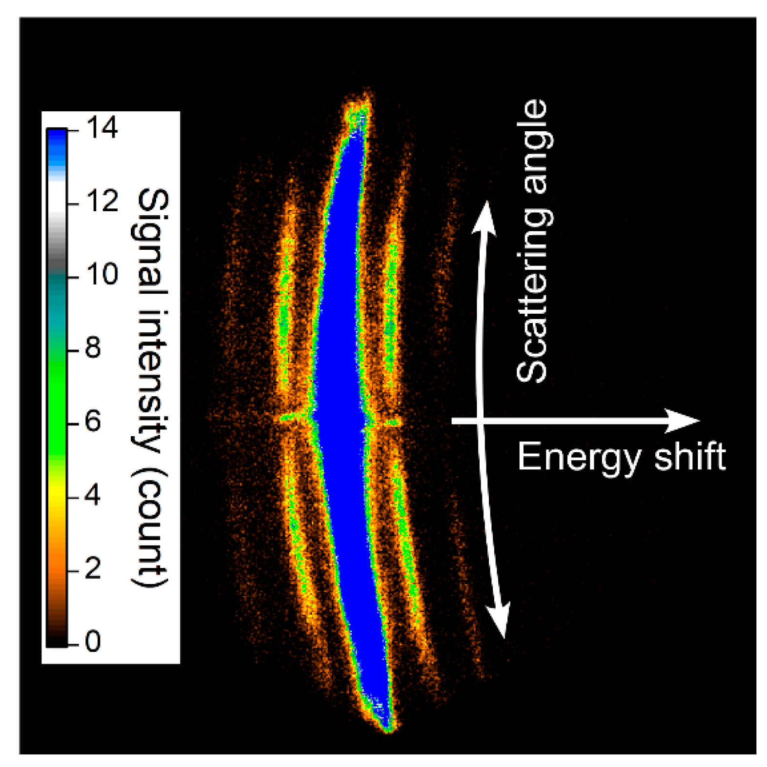
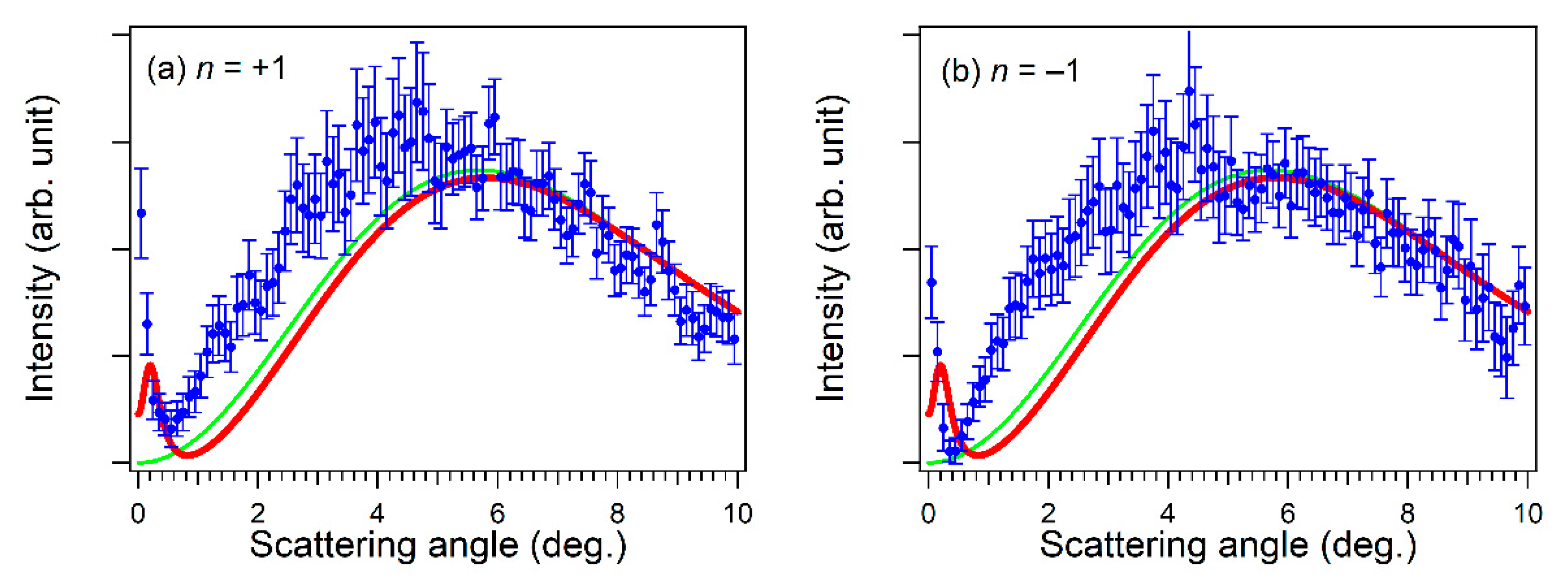
Figure 6 shows the raw image of the scattered electrons when 1 keV electrons were scattered by Xe atoms in an intense laser field (λ = 800 nm, I = 1.5 × 10¹² W/cm2, Δt = 970 fs) [10]. The intense arcuate line, seen in the center of the image, is the elastic scattering signal without energy shifts, and the weaker side arcuate lines are the LAES signals of n = ±1 and ±2. Blue filled circles in Figure 7a are the recorded energy spectrum of the LAES signals obtained after the integration of the electron signals over the angular range of 0.1° ≤ θ ≤ 10°. The LAES signals of n = ±1 and n = ±2 can clearly be recognized in the spectrum at the energy shifts of ±1.55 eV and ±3.10 eV, respectively, and the simulated energy spectrum based on the Kroll–Watson theory [15] (green solid line) was in good agreement with the experimental data. In contrast, as shown in Figure 7b, the intensity of the experimental energy spectrum of the n = ±1 LAES signals within the small angular range of 0.1° ≤ θ ≤ 0.5° was one order of magnitude larger than the intensity of the corresponding energy spectrum obtained by the simulation based on the Kroll–Watson theory [15].
Figure 8a,b show the angular distributions of the LAES signals of n = +1 and n = −1, respectively. In both of the angular distributions, a peak profile was recognized in the small scattering angle range (<0.5 ), which was not reproduced by the simulation based on the Kroll–Watson theory (green solid lines), as expected from the theoretical study on the light-dressing effect in the target atoms [23]. In order to confirm that the observed peak profile originated from the light-dressing effect in Xe atoms, we performed a numerical simulation based on Zon’s model [21].
In Zon’s model, the laser-atom interaction is treated as a polarization of an electron cloud in a target atom, creating a laser-induced dipole moment expressed as
μ ind = a ( ω ) F sin ω t ,
where a(ω) is the frequency-dependent polarizability of the target atom, which can be described by the Unsöld expression [73] expressed as
a ( ω ) = ω res 2 ω res 2 ω 2 ,
where ωres is the resonance frequency of the target atom and ωres >> ω is assumed. Because the scattering process is affected by the interaction potential between the charge of the incident electron and the laser-induced dipole of the polarized atom, the Hamiltonian of the system is expressed as
H ^ = 1 2 m e [ i r + m e ω α 0 cos ω t ] 2 + V ( r ) e 4 π ε 0 r 3 μ ind r ,
Under the first Born approximation, the differential cross section of the LAES process can be derived analytically as
d σ Zon ( n ) d Ω = | p f | | p i | | J n ( α 0 s ) f FBA ( s ) m e 2 ω 2 a ( ω ) 4 π ε 0 2 | s | 2 α 0 s [ J n 1 ( α 0 s ) J n + 1 ( α 0 s ) ] | 2 ,
where fFBA(s) is the scattering amplitude without laser fields expressed as
f FBA ( s ) = m e 2 π 2 d r V ( r ) exp [ i s r ] ,
in the first Born approximation. The first term in the squared modulus in Equation (15) represents the scattering by the field-free potential, V(r), and the second term in the squared modulus represents the laser-induced polarization of the target atom. If the second term in Equation (15) is omitted, Equation (15) becomes identical to Equation (1).
As shown in Figure 8a,b, the angular distributions of the LAES signals of n = ±1 simulated using Zon’s model (red solid lines) qualitatively reproduce the observed peak profile at the small scattering angle range (<0.5°), showing that the observed peak profile originates from the light-dressing in Xe atoms induced by the intense laser field. From further theoretical analyses of the deviation of the observed angular distributions from the simulations based on Zon’s model, we will be able to extract information on the ultrafast evolution of the electron density distribution in the light-dressed Xe atoms.

6.3. High-Order LAES Processes and Assignment of Collision Times

When LAES processes are induced by multi-cycle laser electric fields expressed as F0cosωt, the mechanism of the LAES process can be described in terms of a dimensionless parameter, ξ, defined as
ξ = α 0 s .
When |ξ| >> |ΔE| = |nħω|, the LAES processes can be described in terms of the scattering trajectories of classical mechanical electrons in a laser field. Consequently, the collision time, tc, (i.e., the time when the electron-atom collision occurs) can be expressed as
t c = ± ω 1 arccos n ξ + m T ,
where m is an arbitrary integer and T is the laser field period. Equation (10) shows that the collision time within the optical cycle can be estimated from the energy shift and the deflection angle of scattered electrons.
Figure 9a shows the energy-resolved angular distribution obtained from the measurements of LAES by Xe atoms in a multi-cycle near-infrared laser field (Δt = 100 fs, λ = 800 nm, I = 8.8 × 10¹² W/cm2) using a 1 keV electron beam [66]. If it is assumed that the scattering occurs around the peak field intensity, the collision times can be estimated by Equation (18). For example, the collision times for the LAES signals at the scattering angles of ±11.8°, which are expressed as the square areas enclosed by the broken lines in Figure 9a, are shown by the arrows in Figure 9b for the respective harmonic orders, n = ΔE/(ħω), showing that slight differences in the collision times of the order of 10 attoseconds can be discriminated.

7. Ultrafast Gas Electron Diffraction by LAES Processes

7.1. Laser-Assisted Electron Diffraction

Gas electron diffraction has been a standard method to determine the geometrical structures of molecules in the gas phase [74,75,76]. To probe the temporal variation of geometrical structures of molecules, a pulsed gas electron diffraction method was developed, where electron diffraction patterns were obtained using ultrashort electron pulses with the kinetic energies of 10–100 keV [77]. However, due to the velocity mismatch [64] between laser pulses and electron pulses, the temporal resolution of gas electron diffraction with non-relativistic electron pulses could not be improved beyond ~1 ps [78], which is much longer than the typical timescale of the nuclear motion of molecules. Recently, gas electron diffraction with relativistic electron pulses, where the velocity mismatch problem was solved in the collinear configuration between the laser beam and the electron beam, has been demonstrated, and the relatively slow nuclear dynamics of photoexcited I2 [79] and CF3I [80] molecules were investigated with the temporal resolutions of 230 fs and 150 fs, respectively. However, up to now, a temporal resolution better than 100 fs has not been achieved by the time-resolved pulsed gas electron diffraction method.
As discussed in Section 4, a new ultrafast gas electron diffraction method called laser-assisted electron diffraction (LAED) can be developed if the femtosecond LAES measurements are performed with a molecular target. The schematic of the LAED experiment is described in Figure 10 [81]. The LAES process for molecular targets is basically the same as that for atomic targets, but interference patterns appear in the angular distribution of the LAES signals in the same manner as in conventional gas electron diffraction experiments. From the analyses of the diffraction patterns, the geometrical structure of molecules can be determined. Considering that LAES signals only arise when molecules interact with an ultrashort pulsed laser field, we can regard the determined geometrical structure as an “instantaneous structure” only during the period when the molecules interact with the femtosecond laser pulse. Therefore, if dynamical processes of molecules are induced by femtosecond pump laser pulses and are probed by the femtosecond LAED method, the temporal resolution of the time-resolved gas electron diffraction will be of the order of femtoseconds.
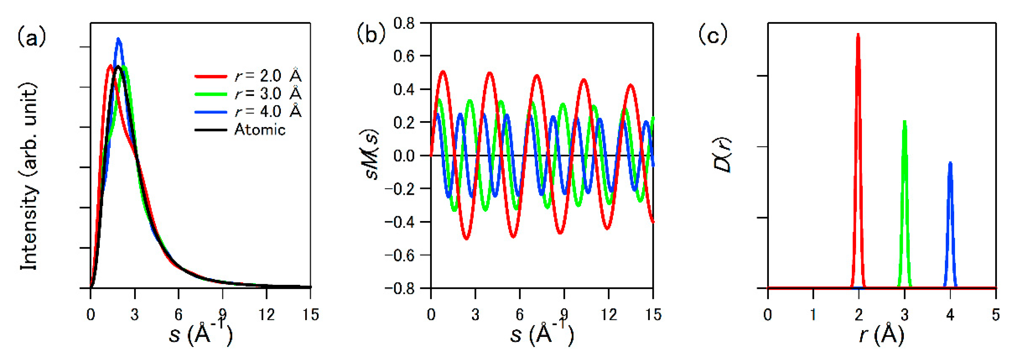
The feasibility of the proposed LAED method was examined through numerical calculations [9]. Figure 11a shows the results of numerical calculations of the scattering intensities of Cl2 as a function of s = |s| for the n = +1 signal of LAES with the three different Cl–Cl internuclear distances; 2.0 Å, 3.0 Å, and 4.0 Å. In the numerical calculations, it was assumed that the 1 keV electrons are scattered by randomly oriented Cl2 molecules in a laser field whose parameters are Δt = 200 fs, λ = 800 nm, and I = 1.8 × 10¹² W/cm2 [9]. Through the same procedure as in the conventional gas electron diffraction method [74,75,76], a modified molecular scattering intensity, sM(s), was obtained as shown in Figure 11b from the observed angular distribution, and a radial distribution curve, D(r), was derived as shown in Figure 11c through the Fourier transform of sM(s). In calculating the differential cross sections of the LAES processes, we adopted KWA, which is known to hold well for high-energy electron scattering in near-infrared laser fields as long as the dressing effect of targets can be neglected. As the geometrical structures of molecules are determined from the LAES signals in a relatively large scattering angle range, the light-dressing effect, which is expected to appear around the zero scattering angle region (|s| < 0.3 Å) as seen in Figure 8, could have only a negligibly small effect on the geometrical structure of molecules to be determined. Therefore, both the formation of light-dressed states and the variation of geometrical structure can be investigated by the analysis of recorded LAED signals.
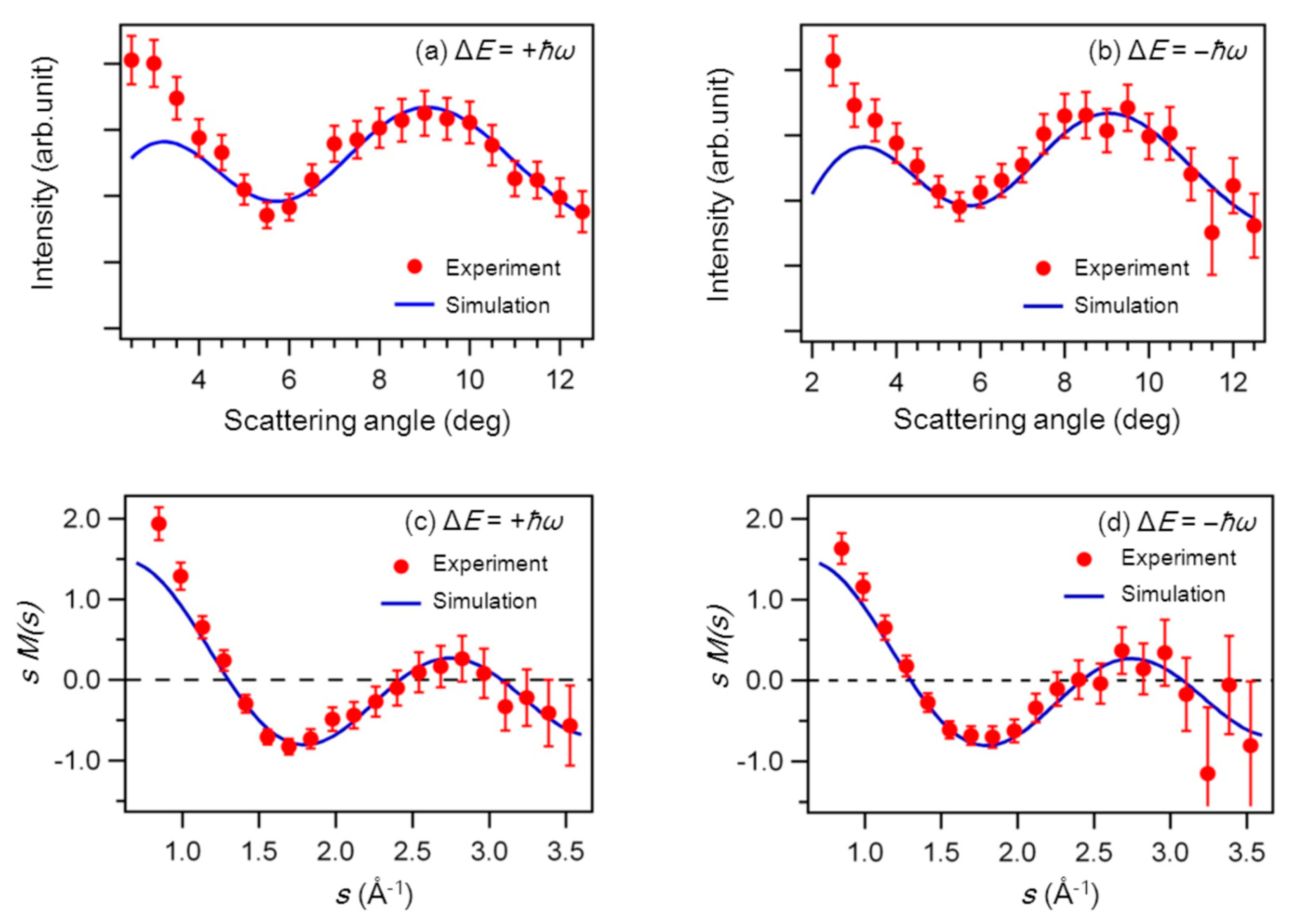
In 2014, we recorded the LAED patterns of gas-phase CCl4 (i.e., electron diffraction patterns) appearing through the interference among the LAES electrons scattered by the respective atoms within a molecule at the energy shifts (ΔE) of ±ħω [58]. In this experiment, the kinetic energy of the incident electrons was 1 keV, and the laser-field parameters were Δt = 520 fs, λ = 800 nm, and I = 6 × 10¹¹ W/cm2. The angular distributions of the one-photon LAES signals (∆E = ±ħω) are shown in Figure 12a,b as red circles [82]. In both of these two angular distributions, we observed clear interference structures exhibiting a minimum around 5.5° and a maximum around 9.0°. In order to confirm the origin of the interference patterns, we conducted a numerical simulation based on the Kroll–Watson approximation [15] and the independent atomic model (IAM) [70] with corrections for the polarization effect induced by the incident electrons and the chemical bonds. We adopted the structural parameters of CCl4 at room temperature [83] determined by the conventional gas-phase electron diffraction (GED). The details of the simulation are given in [60]. The simulated LAES angular distributions represented by solid blue curves in Figure 12a,b are in good agreement with the experimental distributions, showing that the LAED patterns of CCl4 were recorded.
We derived a modified molecular scattering intensity, sM(s) by using the recorded LAED patterns as shown in Figure 12c,d with red filled circles [82]. For comparison, we also show the sM(s) curves calculated based on IAM with the blue solid curves. The agreement between the experimentally obtained sM(s) and the calculated sM(s) shows that the geometrical structure of the molecules at the moment of the laser irradiation can be determined from the analysis of LAED patterns with a precision as high as 0.01 Å, which is typically achieved in the conventional GED.
The LAED method has similarities to the laser-induced electron diffraction (LIED) method proposed theoretically by Zuo et al. [84]. In the LIED method, geometrical structures of molecules are estimated on the basis of quantitative rescattering theory [85,86,87] from electron diffraction patterns that appear as angular distributions in the photoelectron spectra of high-order above-threshold ionization of molecules. In both of the LAES method and LIED method, the temporal resolutions are determined by the laser-pulse duration through the optical gating schemes. When the optical streaking scheme is adopted, the temporal resolutions can become higher and sub-optical cycle resolution can be achieved in both of these two methods. Recently, the LIED method was applied to estimate geometrical structures of diatomic molecules such as N2 and O2 molecules [88,89,90,91,92] and polyatomic molecules such as CO2 [89], C2H2 [92,93,94], CS2 [95], and C60 [96].

7.2. THz-Wave-Assisted Electron Diffraction

Recently, we proposed another electron diffraction method where electron diffraction patterns were streaked by laser-assisted elastic electron scattering (LAES) processes induced by single-cycle or few-cycle laser pulses [11]. If single-cycle THz-wave pulses are used as streaking electric fields affecting the electron diffraction process, a series of snapshots of electron diffraction patterns of isolated molecules can be obtained with femtosecond temporal resolution, that is, dynamical processes of molecules can be recorded in real time without scanning the pump–probe time delay.
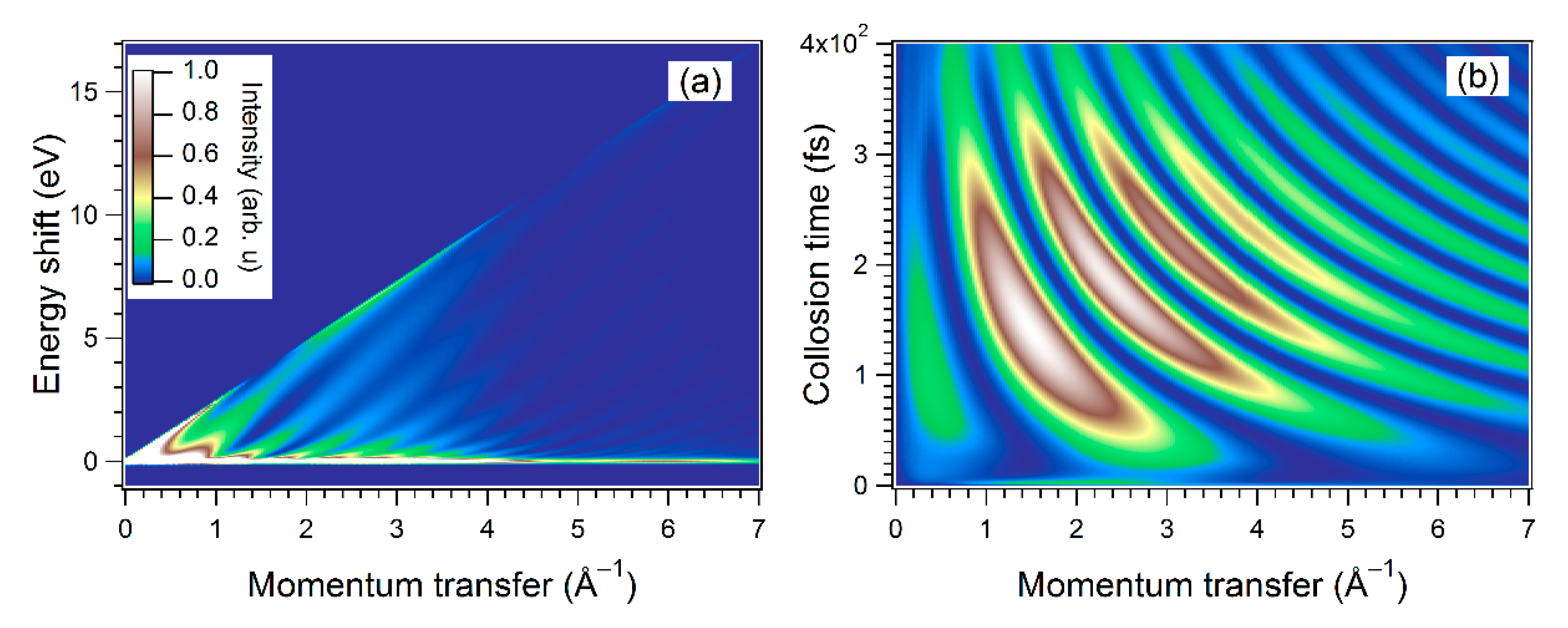
By using Equation (5), we performed numerical simulations to derive the differential cross section of the scattering of 1 keV electrons by Cl2 in a single-cycle THz pulse whose peak electric field intensity and peak frequency were 80 kV/cm and 1.0 THz, respectively. In the simulation, the molecular axis was set to be parallel to the laser polarization direction, and the direction of the incident electron beam was set to be perpendicular to the molecular axis. Figure 13a shows the simulated electron scattering signals for dissociating Cl2. The maximum energy shift of ~17 eV corresponds to extremely high-order multiphoton processes in which more than 4 × 10³ photons are involved. Through the transformation from the energy shift (ΔE) axis to the collision time (tc) axis using Equation (9), it was confirmed that the electron diffraction pattern varying in real time could be obtained by the TAED measurement with a fixed pump–probe delay time, as shown in Figure 13b. From the recorded time-dependent diffraction pattern, the internuclear distances were retrieved as a function of time with the precision higher than 1.5 × 10⁻³ Å. Assuming that the spatial variation of the electric field strength of the THz wave at the scattering point was around 3%, we estimated that the temporal resolution can be higher than 10 fs. This means that the geometrical structures of molecules can be determined by the TAED method with a temporal resolution of sub-10 fs and a spatial resolution of around 10−3Å.

8. Future Prospects

The next important step of the application of the LAES processes induced by a femtosecond laser field will be the measurements of time-resolved LAED with a pump–probe scheme and the measurements of TAED, in both of which sub-10 fs temporal resolution can be achieved. The temporal resolution of LAES can be further improved by up to several tens of attoseconds through the optical streaking method with near-single-cycle mid-infrared laser pulses, which can now be generated, for example, by filamentation in gases [97], adiabatic difference frequency generation [98], and optical parametric chirped pulse amplification followed by the fiber compression scheme [99,100]. Another important step of the application of the LAES processes is investigation of spatiotemporal evolution of light-dressed electronic states to be examined by the analyses of a light-dressing effect in LAES processes.

Author Contributions

Writing—Original Draft Preparation, R.K.; Writing—Review & Editing, K.Y.; Funding Acquisition, R.K. and K.Y.

Funding

This work was supported by JSPS KAKENHI (Grants No. 15H05696 and No. 17H03004), and through a grant from the Morino Foundation for Molecular Science.

Conflicts of Interest

The authors declare no conflicts of interest.

References

  1. Morgan, C.G. Laser-induced breakdown of gases. Rep. Prog. Phys. 1975, 38, 621–665. [Google Scholar] [CrossRef]
  2. Corkum, P.B. Plasma perspective on strong field multiphoton ionization. Phys. Rev. Lett. 1993, 71, 1994–1997. [Google Scholar] [CrossRef] [PubMed] [Green Version]
  3. Kulander, K.C.; Schafer, K.J.; Krause, J.L. Dynamics of Short-Pulse Excitation, Ionization and Harmonic Conversion. In Intercalation in Layered Materials; Springer Science and Business Media LLC: Berlin, Germany, 1993; Volume 316, pp. 95–110. [Google Scholar]
  4. Wilke, M.; Al-Obaidi, R.; Moguilevski, A.; Köthe, A.; Engel, N.; Metje, J.; Kiyan, I.Y.; Aziz, E. Laser-assisted electron scattering in strong-field ionization of dense water vapor by ultrashort laser pulses. New J. Phys. 2014, 16, 83032. [Google Scholar] [CrossRef]
  5. Barna, I.F.; Pocsai, M.A.; Varró, S. The influence of a strong infrared radiation field on the conductance properties of doped semiconductors. Eur. Phys. J. Appl. Phys. 2018, 84, 20101. [Google Scholar] [CrossRef]
  6. Weingartshofer, A.; Jung, C. Multiphoton free-free transitions. In Multiphoton Ionization of Atoms; Chin, S.L., Ed.; Academic Press: Toronto, ON, Canada, 1984; pp. 155–187. [Google Scholar]
  7. Masion, N.J. Laser-assisted electron-atom collisions. Rep. Prog. Phys. 1993, 56, 1275. [Google Scholar] [CrossRef]
  8. Ehlotzky, F.; Jaroń, A.; Kamiński, J. Electron–atom collisions in a laser field. Phys. Rep. 1998, 297, 63–153. [Google Scholar] [CrossRef]
  9. Kanya, R.; Morimoto, Y.; Yamanouchi, K. Observation of Laser-Assisted Electron-Atom Scattering in Femtosecond Intense Laser Fields. Phys. Rev. Lett. 2010, 105, 123202. [Google Scholar] [CrossRef]
  10. Morimoto, Y.; Kanya, R.; Yamanouchi, K. Light-Dressing Effect in Laser-Assisted Elastic Electron Scattering by Xe. Phys. Rev. Lett. 2015, 115, 123201. [Google Scholar] [CrossRef] [Green Version]
  11. Kanya, R.; Yamanouchi, K. Numerical simulation of THz-wave-assisted electron diffraction for ultrafast molecular imaging. Phys. Rev. A 2017, 95, 033416. [Google Scholar] [CrossRef]
  12. Bunkin, F.V.; Fedorov, M. Bremsstrahlung in a strong radiation field. Sov. Phys. JETP 1966, 22, 844. [Google Scholar]
  13. Gordon, W. Der Comptoneffekt nach der Schrödingerschen Theorie. Eur. Phys. J. A 1926, 40, 117–133. [Google Scholar]
  14. Volkov, D.M. Über eine Klasse von Lösungen der Diracschen Gleichung. Z. Phys. 1935, 94, 250. [Google Scholar]
  15. Kroll, N.M.; Watson, K.M. Charged-Particle Scattering in the Presence of a Strong Electromagnetic Wave. Phys. Rev. A 1973, 8, 804–809. [Google Scholar] [CrossRef] [Green Version]
  16. Jablonski, A.; Salvat, F.; Powell, C.J. NIST Electron Elastic-Scattering Cross-Section Database—Version 4.0. Natl. Inst. Stand. Technol. 2002. [Google Scholar]
  17. Gersten, J.I.; Mittleman, M.H. Electron scattering from atoms in the presence of a laser field. Phys. Rev. A 1976, 13, 123–130. [Google Scholar] [CrossRef]
  18. Mittleman, M.H. Electron scattering from atoms in the presence of a laser field. II. Phys. Rev. A 1976, 14, 1338–1344. [Google Scholar] [CrossRef]
  19. Mittleman, M.H. Electron scattering from atoms in the presence of a laser field. III. Phys. Rev. A 1977, 16, 1549–1551. [Google Scholar] [CrossRef]
  20. Mittleman, M.H. Electron scattering from atoms in the presence of a laser field. IV. Phys. Rev. A 1978, 18, 685–688. [Google Scholar] [CrossRef]
  21. Zon, B.A. Bremsstrahlung in collisions between electrons and atoms. Sov. Phys. JETP 1977, 46, 65. [Google Scholar]
  22. Zon, A.B.; Beilin, E.L. On the sum rule for multiphoton bremsstrahlung. J. Phys. B At. Mol. Phys. 1983, 16, L159–L161. [Google Scholar]
  23. Byron, F.W., Jr.; Joachain, C.J. Electron-atom collisions in a strong laser field. J. Phys. B At. Mol. Phys. 1984, 17, L295–L301. [Google Scholar] [CrossRef]
  24. Byron, F.W., Jr.; Francken, P.; Joachain, C.J. Laser-assisted elastic electron-atom collisions. J. Phys. B At. Mol. Phys. 1987, 20, 5487–5503. [Google Scholar] [CrossRef]
  25. Faisal, F.H.M. Theory of Multiphoton Processes; Springer: New York, NY, USA, 1987. [Google Scholar]
  26. Dörr, M.; Joachain, C.J.; Potvliege, R.M.; Vucic, S. Born-Floquet theory of laser-assisted electron-atom collisions. Phys. Rev. A 1994, 49, 4852–4863. [Google Scholar] [CrossRef] [PubMed]
  27. Burke, P.G.; Francken, P.; Joachain, C.J. R-matrix-Floquet theory of multiphoton processes. J. Phys. B At. Mol. Opt. Phys. 1991, 24, 761–790. [Google Scholar] [CrossRef]
  28. Terao-Dunseath, M.; Dunseath, K.M. R-matrix Floquet theory for laser-assisted electron-atom scattering. J. Phys. B 2002, 35, 125. [Google Scholar] [CrossRef]
  29. Cionga, A.; Dimou, L.; Faisal, F.H.M. Differential cross sections of low-energy electron - hydrogen scattering in a laser field. J. Phys. B At. Mol. Opt. Phys. 1997, 30, L361–L370. [Google Scholar] [CrossRef]
  30. Moore, L.; Lysaght, M.; Nikolopoulos, L.; Parker, J.; Van Der Hart, H.; Taylor, K.; Nikolopoulos, L. The RMT method for many-electron atomic systems in intense short-pulse laser light. J. Mod. Opt. 2011, 58, 1132–1140. [Google Scholar] [CrossRef]
  31. Andrick, D.; Langhans, L. Measurement of free-free transitions in e--Ar scattering. J. Phys. B At. Mol. Phys. 1976, 9, L459–L461. [Google Scholar] [CrossRef]
  32. Andrick, D.; Langhans, L. Measurement of the free-free cross section of e--Ar scattering. J. Phys. B At. Mol. Phys. 1978, 11, 2355–2360. [Google Scholar] [CrossRef]
  33. Langhans, L. Resonance structures in the free-free cross section of e--Ar scattering. J. Phys. B At. Mol. Phys. 1978, 11, 2361–2366. [Google Scholar] [CrossRef]
  34. Andrick, D.; Bader, H. Resonance structures in the cross section for free-free radiative transitions in e--He scattering. J. Phys. B At. Mol. Phys. 1984, 17, 4549–4555. [Google Scholar] [CrossRef]
  35. Bader, H. Resonance structures in the cross section for free-free radiative transitions in e--Ne and e--Ar scattering. J. Phys. B At. Mol. Phys. 1986, 19, 2177–2188. [Google Scholar] [CrossRef]
  36. Weingartshofer, A.; Holmes, J.K.; Caudle, G.; Clarke, E.M.; Krüger, H. Direct Observation of Multiphoton Processes in Laser-Induced Free-Free Transitions. Phys. Rev. Lett. 1977, 39, 269–270. [Google Scholar] [CrossRef]
  37. Wallbank, B.; Holmes, J.K.; MacIsaac, S.C.; Weingartshofer, A. Resonance structures in free-free cross sections for electron-helium scattering. J. Phys. B At. Mol. Opt. Phys. 1992, 25, 1265–1277. [Google Scholar] [CrossRef]
  38. Wallbank, B.; Holmes, J.K. Laser-assisted elastic electron-atom collisions. Phys. Rev. A 1993, 48, R2515–R2518. [Google Scholar] [CrossRef] [PubMed]
  39. Wallbank, B.; Holmes, J.K. Laser-assisted elastic electron-atom collisions: Low electron energy and small scattering angle. J. Phys. B At. Mol. Opt. Phys. 1994, 27, 1221–1231. [Google Scholar] [CrossRef]
  40. Wallbank, B.; Holmes, J.K. Low-energy electron - helium scattering in a laser field. J. Phys. B At. Mol. Opt. Phys. 1996, 29, 5881–5887. [Google Scholar] [CrossRef]
  41. Wallbank, B.; Holmes, J.K. Laser-assisted elastic electron scattering from helium. Can. J. Phys. 2001, 79, 1237–1246. [Google Scholar] [CrossRef]
  42. Nehari, D.; Holmes, J.; Dunseath, K.M.; Terao-Dunseath, M. Experimental and theoretical study of free–free electron–helium scattering in a CO2 laser field. J. Phys. B At. Mol. Opt. Phys. 2010, 43, 25203. [Google Scholar] [CrossRef]
  43. Weingartshofer, A.; Clarke, E.M.; Holmes, J.K.; Jung, C. Experiments on multiphoton free-free transitions. Phys. Rev. A 1979, 19, 2371–2376. [Google Scholar] [CrossRef]
  44. Weingartshofer, A.; Holmes, J.K.; Sabbagh, J.; Chin, S.L. Electron scattering in intense laser fields. J. Phys. B At. Mol. Phys. 1983, 16, 1805–1817. [Google Scholar] [CrossRef]
  45. Wallbank, B.; Connors, V.W.; Holmes, J.K.; Weingartshofer, A. Experimental differential cross sections for one-photon free-free transitions. J. Phys. B At. Mol. Phys. 1987, 20, L833–L838. [Google Scholar] [CrossRef]
  46. Wallbank, B.; Holmes, J.K.; Weingartshofer, A. Experimental differential cross sections for multiphoton free-free transitions. J. Phys. B At. Mol. Phys. 1987, 20, 6121–6138. [Google Scholar] [CrossRef]
  47. Wallbank, B.; Holmes, J.K. Differential cross sections for laser-assisted elastic electron scattering from argon. J. Phys. B At. Mol. Opt. Phys. 1994, 27, 5405–5418. [Google Scholar] [CrossRef]
  48. Musa, O.M.; Macdonald, A.; Tidswell, L.; Holmes, J.; Wallbank, B. Laser-induced free–free transitions in elastic electron scattering from CO2. J. Phys. B At. Mol. Opt. Phys. 2010, 43, 175201. [Google Scholar] [CrossRef]
  49. Mason, N.J.; Newell, W.R. Simultaneous electron-photon excitation of the helium 23S state. J. Phys. B At. Mol. Phys. 1987, 20, L323–L325. [Google Scholar] [CrossRef]
  50. Wallbank, B.; Holmes, J.K.; Blanc, L.; Weingartshofer, A. Simultaneous off-shell excitation of He 23S by an electron and one or more photons. Eur. Phys. J. D 1988, 10, 467–472. [Google Scholar] [CrossRef]
  51. Wallbank, B.; Holmes, J.K.; Weingartshofer, A. Simultaneous electron-photon excitation of metastable states of rare-gas atoms. J. Phys. B At. Mol. Opt. Phys. 1989, 22, L615–L619. [Google Scholar] [CrossRef]
  52. Mason, N.J.; Newell, W.R. Simultaneous electron-photon excitation of the helium 23S state. J. Phys. B At. Mol. Opt. Phys. 1989, 22, 777–796. [Google Scholar] [CrossRef]
  53. Mason, N.J.; Newell, W.R. The polarisation dependence of the simultaneous electron-photon excitation cross section of the helium 23S state. J. Phys. B At. Mol. Opt. Phys. 1990, 23, L179–L182. [Google Scholar] [CrossRef]
  54. Wallbank, B.; Holmes, J.K.; Weingartshofer, A. Simultaneous electron-photon excitation of He 23S: An experimental investigation of the effects of laser intensity and polarisation. J. Phys. B At. Mol. Opt. Phys. 1990, 23, 2997–3005. [Google Scholar] [CrossRef]
  55. Luan, S.; Hippler, R.; Lutz, H.O. Simultaneous electron-photon excitation of helium (ħω=1.17 eV). J. Phys. B 1991, 24, 3241. [Google Scholar] [CrossRef]
  56. Wallbank, B.; Holmes, J.K.; Weingartshofer, A. Absorption and emission of radiation during electron excitation of the 2 1S and 2 1P states of helium. Phys. Rev. A 1989, 40, 5461–5463. [Google Scholar] [CrossRef]
  57. Wallbank, B.; Holmes, J.K.; Weingartshofer, A. Electron impact excitation of He 21P in the presence of a nonresonant laser field. Can. J. Phys. 1993, 71, 326–333. [Google Scholar] [CrossRef]
  58. Morimoto, Y.; Kanya, R.; Yamanouchi, K. Laser-assisted electron diffraction for femtosecond molecular imaging. J. Chem. Phys. 2014, 140, 64201. [Google Scholar] [CrossRef] [PubMed]
  59. Itatani, J.; Quéré, F.; Yudin, G.L.; Ivanov, M.Y.; Krausz, F.; Corkum, P.B. Attosecond Streak Camera. Phys. Rev. Lett. 2002, 88, 173903. [Google Scholar] [CrossRef] [PubMed]
  60. Scrinzi, A.; Kitzler, M.; Milosevic, N.; Krausz, F.; Brabec, T. Quantum Theory of Attosecond XUV Pulse Measurement by Laser Dressed Photoionization. Phys. Rev. Lett. 2002, 88, 173904. [Google Scholar]
  61. Baker, S.; Robinson, J.S.; Haworth, C.A.; Teng, H.; Smith, R.A.; Chirila, C.C.; Lein, M.; Tisch, J.W.G.; Marangos, J.P. Probing Proton Dynamics in Molecules on an Attosecond Time Scale. Science 2006, 312, 424–427. [Google Scholar] [CrossRef] [Green Version]
  62. Blaga, C.I.; Xu, J.; DiChiara, A.D.; Sistrunk, E.; Zhang, K.; Agostini, P.; Miller, T.A.; DiMauro, L.F.; Lin, C.D. Imaging ultrafast molecular dynamics with laser-induced electron diffraction. Nature 2012, 483, 194–197. [Google Scholar] [CrossRef]
  63. Kanya, R.; Morimoto, Y.; Yamanouchi, K. Apparatus for laser-assisted electron scattering in femtosecond intense laser fields. Rev. Sci. Instrum. 2011, 82, 123105. [Google Scholar] [CrossRef]
  64. Williamson, J.C.; Zewail, A.H. Ultrafast electron diffraction. Velocity mismatch and temporal resolution in crossed-beam experiments. Chem. Phys. Lett. 1993, 209, 10–16. [Google Scholar] [CrossRef]
  65. Toffoletto, F.; Leckey, R.; Riley, J. Design criteria for an angle resolved electron spectrometer of novel toroidal geometry. Nucl. Instrum. Methods Phys. Res. Sect. B Beam Interact. Mater. At. 1985, 12, 282–297. [Google Scholar] [CrossRef]
  66. Ishida, K.; Morimoto, Y.; Kanya, R.; Yamanouchi, K. High-order multiphoton laser-assisted elastic electron scattering by Xe in a femtosecond near-infrared intense laser field: Plateau in energy spectra of scattered electrons. Phys. Rev. A 2017, 95, 023414. [Google Scholar] [CrossRef]
  67. Deharak, B.A.; Ladino, L.; Macadam, K.B.; Martin, N.L.S. High-energy electron-helium scattering in a Nd:YAG laser field. Phys. Rev. A 2011, 83, 022706. [Google Scholar] [CrossRef]
  68. Deharak, B.A.; Nosarzewski, B.; Siavashpouri, M.; Martin, N.L.S. Electron-helium scattering in a 1.17 eV laser field: The effect of polarization direction. Phys. Rev. A 2014, 90, 032709. [Google Scholar] [CrossRef]
  69. Deharak, A.B.; Kim, B.N.; Weaver, C.M.; Martin, N.L.S.; Siavashpouri, M.; Nosarzewski, B. Effects of polarization direction on laser-assisted free–free scattering. Plasma Sources Sci. Technol. 2016, 25, 35021. [Google Scholar] [CrossRef]
  70. Martin, N.L.S.; Deharak, B.A. Test of target independence for free-free scattering in a Nd:YAG laser field. Phys. Rev. A 2016, 93, 013403. [Google Scholar] [CrossRef]
  71. Martin, N.L.S.; Weaver, C.M.; Kim, B.N.; Deharak, B.A. Angular distribution of electrons elastically scattered from Ar in the presence of a 1.17 eV laser field. Phys. Rev. A 2019, 99, 032708. [Google Scholar] [CrossRef] [Green Version]
  72. Martin, N.L.S.; Kim, B.N.; Deharak, A.B.; Weaver, C.M. Free–free experiments: The search for dressed atom effects. J. Phys. B At. Mol. Opt. Phys. 2018, 51, 134003. [Google Scholar] [CrossRef]
  73. Bishop, D.M. Aspects of non-Linear-optical calculations. Adv. Quantum Chem. 1995, 15, 1. [Google Scholar]
  74. Yamanouchi, K.; Sugue, M.; Takeo, H.; Matsumura, C.; Kuchitsu, K. Molecular structure and conformation of 1-chloropropane as determined by gas electron diffraction and microwave spectroscopy. J. Phys. Chem. 1984, 88, 2315–2320. [Google Scholar] [CrossRef]
  75. Hargittai, I.; Hargittai, M. Stereochemical Applications of Gas Phase Electron Diffraction, Part A.; Wiley-VCH Verlag GmbH: New York, NY, USA, 1988. [Google Scholar]
  76. Yamanouchi, K. Quantum Mechanics of Molecular Structures; Springer Science and Business Media LLC: Berlin, Germany, 2012. [Google Scholar]
  77. Srinivasan, R.; Lobastov, V.A.; Zewail, A.H.; Ruan, C.Y.; Ruan, C. Ultrafast Electron Diffraction (UED). A New Development for the 4D Determination of Transient Molecular Structures. Helv. Chim. Acta 2003, 34, 86. [Google Scholar] [CrossRef]
  78. Ihee, H.; Lobastov, V.A.; Gomez, U.M.; Goodson, B.M.; Srinivasan, R.; Ruan, C.Y.; Zewail, A.H. Direct Imaging of Transient Molecular Structures with Ultrafast Diffraction. Science 2001, 291, 458–462. [Google Scholar] [CrossRef] [PubMed] [Green Version]
  79. Guehr, M.; Shen, X.; Li, R.; Vecchione, T.; Corbett, J.; Fry, A.; Hartmann, N.; Hast, C.; Hegazy, K.; Jobe, K.; et al. Diffractive Imaging of Coherent Nuclear Motion in Isolated Molecules. Phys. Rev. Lett. 2016, 117, 153002. [Google Scholar] [Green Version]
  80. Yang, J.; Zhu, X.; Wolf, T.J.A.; Li, Z.; Nunes, J.P.F.; Coffee, R.; Cryan, J.P.; Gühr, M.; Hegazy, K.; Heinz, T.F.; et al. Imaging CF3I conical intersection and photodissociation dynamics with ultrafast electron diffraction. Science 2018, 361, 64. [Google Scholar] [CrossRef] [PubMed]
  81. Kanya, R.; Morimoto, Y.; Yamanouchi, K. Laser-Assisted Electron Scattering and Diffraction in Ultrashort Intense Laser Fields. In Springer Series in Chemical Physics; Springer Science and Business Media LLC: Berlin, Germany, 2014; Volume 106, pp. 1–16. [Google Scholar]
  82. Morimoto, Y.; Kanya, R.; Yamanouchi, K. Laser-Assisted Electron Diffraction for Probing Femtosecond Nuclear Dynamics of Gas-Phase Molecules. In 19th International Conference on Ultrafast Phenomena; OSA Technical Digest (online), paper 09.Wed.C.2; Optical Society of America: Washington, DC, USA, 2014. [Google Scholar]
  83. Morino, Y.; Nakamura, Y.; Iijima, T. Mean square amplitudes and force constants of tetrahedral molecules. I. Carbon tetrachloride and germanium tetrachloride. J. Chem. Phys. 1960, 32, 643. [Google Scholar] [CrossRef]
  84. Zuo, T.; Bandrauk, A.; Corkum, P. Laser-induced electron diffraction: A new tool for probing ultrafast molecular dynamics. Chem. Phys. Lett. 1996, 259, 313–320. [Google Scholar] [CrossRef]
  85. Morishita, T.; Le, A.T.; Chen, Z.; Lin, C.D. Accurate Retrieval of Structural Information from Laser-Induced Photoelectron and High-Order Harmonic Spectra by Few-Cycle Laser Pulses. Phys. Rev. Lett. 2008, 100, 013903. [Google Scholar] [CrossRef] [Green Version]
  86. Chen, Z.; Le, A.T.; Morishita, T.; Lin, C.D. Quantitative rescattering theory for laser-induced high-energy plateau photoelectron spectra. Phys. Rev. A 2009, 79, 033409. [Google Scholar] [CrossRef] [Green Version]
  87. Lin, C.D.; Le, A.T.; Chen, Z.; Morishita, T.; Lucchese, R. Strong-field rescattering physics—Self-imaging of a molecule by its own electrons. J. Phys. B At. Mol. Opt. Phys. 2010, 43, 122001. [Google Scholar] [CrossRef]
  88. Meckel, M.; Comtois, D.; Zeidler, D.; Staudte, A.; Pavičić, D.; Bandulet, H.C.; Pépin, H.; Kieffer, J.C.; Dörner, R.; Villeneuve, D.M.; et al. Laser-Induced Electron Tunneling and Diffraction. Science 2008, 320, 1478. [Google Scholar] [CrossRef] [PubMed]
  89. Okunishi, M.; Niikura, H.; Lucchese, R.R.; Morishita, T.; Ueda, K. Extracting Electron-Ion Differential Scattering Cross Sections for Partially Aligned Molecules by Laser-Induced Rescattering Photoelectron Spectroscopy. Phys. Rev. Lett. 2011, 106, 063001. [Google Scholar] [CrossRef] [PubMed] [Green Version]
  90. Blaga, C.I.; Xu, J.; Di Chiara, A.D.; Sistrunk, E.; Zhang, K.; Agostini, P.; Miller, T.A.; DiMauro, L.F.; Lin, C.D. Imaging ultrafast molecular dynamics with laser-induced electron diffraction. Nature 2012, 483, 194–197. [Google Scholar] [CrossRef] [PubMed]
  91. Xu, J.; Blaga, C.I.; Zhang, K.; Lai, Y.H.; Lin, C.D.; Miller, T.A.; Agostini, P.; DiMauro, L.F. Diffraction using laser-driven broadband electron wave packets. Nat. Commun. 2014, 5, 4635. [Google Scholar] [CrossRef] [PubMed] [Green Version]
  92. Pullen, M.G.; Wolter, B.; Le, A.T.; Baudisch, M.; Sclafani, M.; Pires, H.; Schröter, C.D.; Ullrich, J.; Moshammer, R.; Pfeifer, T.; et al. Influence of orbital symmetry on diffraction imaging with rescattering electron wave packets. Nat. Commun. 2016, 7, 11922. [Google Scholar] [CrossRef] [PubMed] [Green Version]
  93. Pullen, M.G.; Wolter, B.; Le, A.T.; Baudisch, M.; Hemmer, M.; Senftleben, A.; Schröter, C.D.; Ullrich, J.; Moshammer, R.; Lin, C.D.; et al. Imaging an aligned polyatomic molecule with laser-induced electron diffraction. Nat. Commun. 2015, 6, 7262. [Google Scholar] [CrossRef] [PubMed] [Green Version]
  94. Wolter, B.; Pullen, M.G.; Le, A.T.; Baudisch, M.; Doblhoff-Dier, K.; Senftleben, A.; Hemmer, M.; Schröter, C.D.; Ullrich, J.; Pfeifer, T.; et al. Ultrafast electron diffraction imaging of bond breaking in di-ionized acetylene. Science 2016, 354, 308–312. [Google Scholar] [CrossRef] [PubMed] [Green Version]
  95. Amini, K.; Sclafani, M.; Steinle, T.; Le, A.T.; Sanchez, A.; Müller, C.; Steinmetzer, J.; Yue, L.; Saavedra, J.R.M.; Hemmer, M.; et al. Imaging the Renner–Teller effect using laser-induced electron diffraction. Proc. Natl. Acad. Sci. USA 2019, 116, 8173–8177. [Google Scholar] [CrossRef]
  96. Fuest, H.; Lai, Y.H.; Blaga, C.I.; Suzuki, K.; Xu, J.; Rupp, P.; Li, H.; Wnuk, P.; Agostini, P.; Yamazaki, K.; et al. Diffractive Imaging of C60 Structural Deformations Induced by Intense Femtosecond Midinfrared Laser Fields. Phys. Rev. Lett. 2019, 122, 053002. [Google Scholar] [CrossRef]
  97. Nomura, Y.; Shirai, H.; Ishii, K.; Tsurumachi, N.; Voronin, A.A.; Zheltikov, A.M.; Fuji, T. Phase-stable sub-cycle mid-infrared conical emission from filamentation in gases. Opt. Express 2012, 20, 24741–24747. [Google Scholar] [CrossRef]
  98. Krogen, P.; Suchowski, H.; Liang, H.; Flemens, N.; Hong, K.H.; Kärtner, F.X.; Moses, J. Generation and multi-octave shaping of mid-infrared intense single-cycle pulses. Nat. Photonics 2017, 11, 222–226. [Google Scholar] [CrossRef]
  99. Elu, U.; Baudisch, M.; Pires, H.; Tani, F.; Frosz, M.H.; Köttig, F.; Ermolov, A.; Russell, P.S.; Biegert, J. High average power and single-cycle pulses from a mid-IR optical parametric chirped pulse amplifier. Optica 2017, 4, 1024. [Google Scholar] [CrossRef]
  100. Wang, P.; Li, Y.; Li, W.; Su, H.; Shao, B.; Li, S.; Wang, C.; Wang, D.; Zhao, R.; Peng, Y.; et al. 26 mJ/100 Hz CEP-stable near-single-cycle 4 μm laser based on OPCPA and hollow-core fiber compression. Opt. Lett. 2018, 43, 2197–2200. [Google Scholar] [CrossRef] [PubMed]
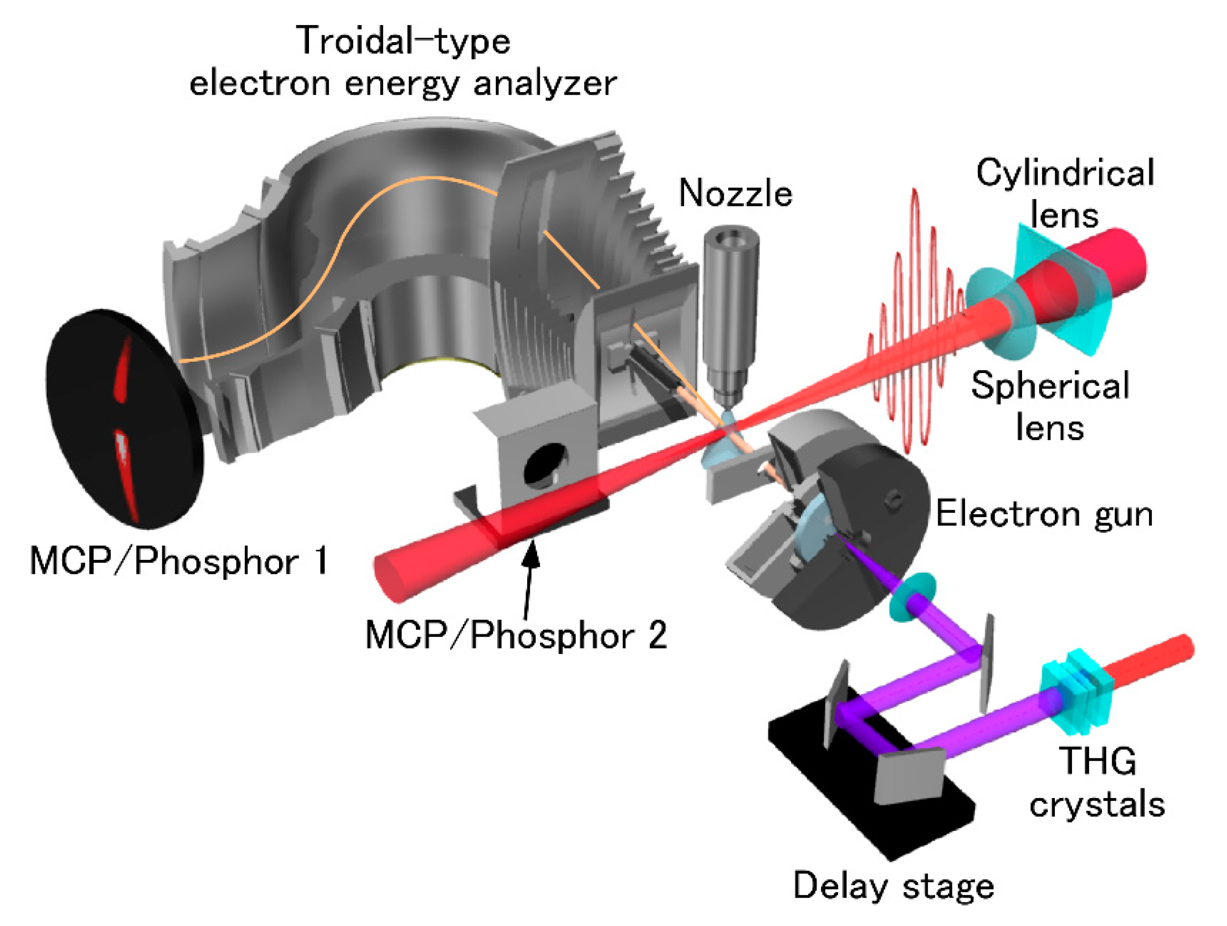
Figure 1. The schematic of the experimental setup of LAES [63]. Reproduced from Kanya, R.; Morimoto, Y.; Yamanouchi, K. “Apparatus for laser-assisted electron scattering in femtosecond intense laser fields.” Rev. Sci. Instrum. 2011, 82, 123105, with the permission of AIP Publishing.
Atoms 07 00085 g001
Figure 2. (a) The raw image of the electron scattering signals recorded when vertically polarized laser pulses (Δt = 200 fs, λ = 800 nm, and I = 1.8 × 10¹² W/cm2) were introduced at the timing of the collision of 1 keV electron pulses by Xe atoms [9]. (b) The amplified image of (a). (c) The raw image of the background signals at the same intensity scale as (b).
Atoms 07 00085 g002
Figure 3. The energy spectra of the relative intensities of scattered electron signals [9]. The intensity was normalized with respect to the peak intensity of the n = 0 scattering signal. Estimated statistical error bars are derived from the square roots of the signal counts. Blue filled circles are the electron signals recorded with vertically polarized laser fields; black filled squares are the background signals; and the black broken line is the n = 0 scattering peak reduced by a factor of 1000. The experimental conditions were the same as those in Figure 2.
Atoms 07 00085 g003
Figure 4. The energy spectra of the relative intensities of the LAES signals [9]. The relative intensities were normalized with respect to the peak intensity of the n = 0 scattering signal. Estimated statistical error bars were derived from the square roots of signal counts. The blue filled circles are the energy spectrum obtained after the subtraction of the backgrounds from the signals recorded with vertically polarized laser fields; the red filled triangles are the energy spectrum obtained after the subtraction of the backgrounds from the signals recorded with horizontally polarized laser fields; and the green solid line is a calculated spectrum of the LAES signals when the laser fields are vertically polarized. The experimental conditions were the same as those in Figure 2.
Atoms 07 00085 g004
Figure 5. The angular distributions of LAES for the n = +1 transitions with the vertically polarized laser field [9]. The blue filled circles are the observed LAES signals of n = +1 and the green solid line is obtained by the numerical calculation by KWA. Estimated statistical error bars were derived from square roots of the signal counts. The experimental conditions are the same as those in Figure 2.
Atoms 07 00085 g005
Figure 6. A raw image of the scattered electrons recorded when 1 keV electrons were scattered by Xe atoms in an intense laser field (λ = 800 nm, I = 1.5 × 10¹² W/cm2, Δt = 970 fs) [10].
Atoms 07 00085 g006
Figure 7. Energy spectra of electrons scattered within the angular ranges of (a) 0.1° ≤ θ ≤ 10.0° and (b) 0.1° ≤ θ ≤ 0.5° [10]. The blue filled circles are the experimental data and the green solid lines are the simulations based on the Kroll–Watson theory. These spectra were obtained by the background subtraction. The experimental conditions are the same as those in Figure 6.
Atoms 07 00085 g007
Figure 8. Angular distributions of the LAES signals of (a) n = +1 and (b) n = −1 [10]. The blue filled circles are the experimental data, the green solid lines are the simulations based on the Kroll–Watson theory, and the red solid lines are the simulations based on Zon’s model. The experimental conditions are the same as those in Figure 6.
Atoms 07 00085 g008
Figure 9. (a) Energy-resolved angular distributions of scattered electrons recorded when 1 keV electrons are scattered by Xe atoms in an intense laser field (λ = 800 nm, I = 1.5 × 10¹² W/cm2, Δt = 970 fs) [66]. (b) Assignments of collision times for LAES processes yielding the scattering angles of ±11.8°. The red solid curve is the electric field of the laser field and the blue dotted vertical lines are the collision times for the respective harmonic orders, n = ΔE/(ħω).
Atoms 07 00085 g009
Figure 10. The schematic of the laser-assisted electron diffraction method [81]. Reprinted by permission from Springer Publishing: Kanya, R.; Morimoto, Y.; Yamanouchi, K. “Laser-assisted electron scattering and diffraction in ultrashort intense laser fields.” In Progress in Ultrafast Intense Laser Science X; Yamanouchi, K., Paulus, G.G., Mathur, D., Eds.; Springer International Publishing: Basel, Switzerland, 2014; pp. 1–16, Chap. 1. © Springer Publishing (2014).
Atoms 07 00085 g010
Figure 11. The model calculations of (a) scattering intensities, (b) sM(s), and (c) D(r) of the LAES by Cl2 molecules with different internuclear distances; r = 2.0 Å (red solid line), 3.0 Å (green solid line), and 4.0 Å (blue solid line) for the n = +1 signal [9]. The mean amplitude was set to be lh = 0.044 Å. The black solid line in (a) represents the atomic scattering intensity of two Cl atoms. The kinetic energy of the incident electrons was 1 keV, and the laser-field parameters were Δt = 200 fs, λ = 800 nm, and I = 1.8 × 10¹² W/cm2.
Atoms 07 00085 g011
Figure 12. (Top panels) Laser-assisted electron diffraction patterns of CCl4 at (a) ∆E = +ħω and (b) ∆E = –ħω. (Bottom panels) Modified molecular scattering intensities calculated from the LAED patterns at (c) ∆E = +ħω and (d) ∆E = –ħω [82]. Red filled circles are the experimental data. Blue solid curves are the results of the simulation. The kinetic energy of the incident electrons was 1 keV, and the laser-field parameters were Δt = 520 fs, λ = 800 nm, and I = 6 × 10¹¹ W/cm2. Reproduced from Y. Morimoto, R. Kanya, and K. Yamanouchi, “Laser-assisted Electron Diffraction for Probing Femtosecond Nuclear Dynamics of Gas-phase Molecules”, in the 19th International Conference on Ultrafast Phenomena, OSA Technical Digest (online) (Optical Society of America, 2014), paper 09.Wed.C.2.
Atoms 07 00085 g012
Figure 13. Results of numerical simulations of LAES obtained when 1 keV electrons are scattered by Cl2 molecules in a single-cycle THz pulse whose peak electric field intensity and peak frequency are 80 kV/cm and 1.0 THz, respectively [11]. (a) Calculated signal distributions of electrons scattered by dissociating Cl2 molecules. (b) Time-resolved electron diffraction patterns obtained from the signal distributions shown in (a).
Atoms 07 00085 g013