1. Introduction
Liquid argon (LAr) Time Projection Chambers (TPC) are playing an increasingly important role in dark matter (DM) [
1,
2,
3] and neutrino experiments [
4,
5]. LAr has the advantage of allowing the construction of large-mass detectors at a reasonable cost, while also enabling the implementation of a fully active tracking calorimeter.
In a typical LAr-TPC, photon sensors detect prompt scintillation light, while electrons drift to the anode under a uniform electric field
. The drift field suppresses the prompt recombination of oppositely charged particles created along the ionization track, causing them to drift towards the anode or cathode along the electric field lines. The mobility,
, of argon ions (
) in liquid is much smaller than that of electrons (
); the latter are thus promptly collected while the former stay in the drift region for a much longer time. For a field of
kV/cm, the electron velocity is of the order of
mm/
[
6]. The ion mobility is not well known, and the values reported in the literature range between approximately
[
7] and
[
8,
9] with the liquid in a steady state. Considering the larger value, the expected ion velocity at 1 kV/cm is
mm/
. The ions therefore spend substantially more time in the drift region before being neutralized at the cathode. As a consequence, the average density of positive ions in the active volume,
, is much larger than that of electrons,
. The positive charge density in the active volume increases with time, eventually reaching a constant value depending on the particle interaction rate in the detector.
This positive space charge can locally modify the drift lines, the magnitude of the electric field, and ultimately the velocity of the electrons, eventually producing a displacement in the reconstructed position of the ionisation signal. Additionally, for relatively large values of
, the high positive-charge density makes it necessary to consider the probability of “secondary recombination” between drifting electrons and free positive ions. This process is different from the recombination that occurs within the ionisation track [
10]. The secondary recombination can cause signal loss, with a probability dependent on the electron drift path, comparable to the charge quenching due to contamination of the electronegative impurities in LAr. At the same time, it can produce the emission of photons through channels similar to the primary recombination light.
The effects caused by the positive volume charge in massive argon detectors can be particularly relevant in case of charge amplification at the anode, as in a dual-phase (liquid–gas) TPC. In this case, the ions created in the vapour volume may cross the gas–liquid interface and further increase in the active LAr volume.
Previous experiments have measured space charge effects in small-scale volumes in liquid argon single-phase detectors [
11,
12]. However, these effects have not been studied with a small dual-phase detector. To study the dynamics of the argon ions in liquid and measure the ion feedback from the gas into the liquid phase, we constructed the ARION (ARgon ION) experiment. The setup consists of a small liquid argon chamber and a system that injects defined positive ion currents in the drift region, producing a sizeable volume charge. In this article, we discuss recent experimental results regarding the dynamics of ions in liquid and the direct measurement of ion feedback from the gas into the liquid phase. Additionally, we present a new measurement of the drift velocity of argon ions in the gas phase.
2. Experimental Setup
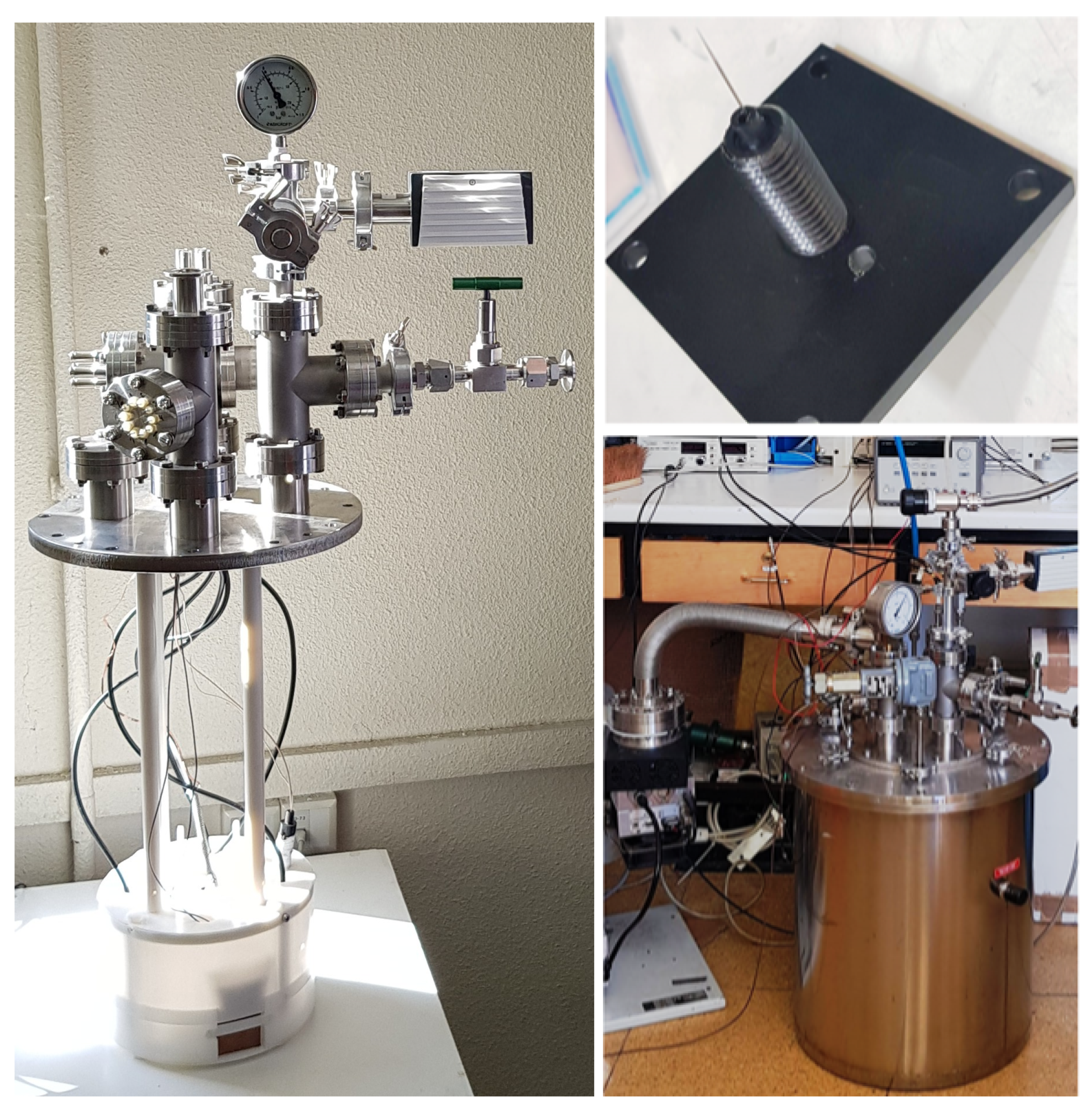
The ARION experiment (
Figure 1 left) consists of a 1 L dual-phase argon chamber with a drift region and charge readout. The anode is a tungsten needle with a 0.5 mm diameter, 3.8 cm height and 1
tip radius, located in the gas region on a Teflon holder supported by a conductive plane (
Figure 1 top-right). The needle is used to produce a sizeable positive current, which is injected into the drift region. The cathode is a mesh of horizontal stainless steel wires with an area of 5 × 5
. Two stainless steel field-shaping rings are placed between the anode and cathode with the goal of ensuring the uniformity of the electric field in the drift region. The bottom shaping ring is separated by 2 cm from the cathode and the top ring. The distance between the anode and cathode is adjusted mechanically, with a maximum of 7 cm. Four bars connect the support structure (Ertalyte [
13] with a Teflon envelope) to a stainless steel vacuum flange. The chamber is enclosed in a cryostat (
Figure 1 bottom-right) equipped with temperature and liquid-level sensors. Five connections are used to power independently the anode, cathode, two shaping rings, and conductive plane around the needle. A vacuum of 10
mbar is reached before filling the detector with argon gas at room temperature. During operation the pressure inside the cryostat is kept under 1.5 bar by a spring relief valve.
The liquid-level inside the chamber is measured by two custom capacitance-based sensors installed vertically with the bottom part at 0.5 cm from the cathode. The first one is made of two concentric copper cylinders with a length of 12 cm. The second one is smaller, but more precise, than the first and consists of a series of parallel planes totaling 7 cm in height. The capacitance variation is used to estimate the LAr level with uncertainties of 2 mm (17%) and 0.35 mm (5%), respectively. The sensors are calibrated by measuring the capacitance both in air and fully covered with
. The corresponding capacitance in LAr,
, is estimated from the following expression:
where
and
are the dielectric constants of LAr (1.5) and
(1.4), and
is the capacitance measured in
. The liquid-level in the detector is estimated by combining both sensors, permitting control of the argon filling rate, which is approximately 0.02 L/min. The temperature is measured with two PT100 resistors at the bottom of the level sensors.
In the experiment, the voltage of the anode is set to a maximum of 5 kV. The electrons created near the needle by the Townsend avalanche are directly collected at the plane around the needle and the positive ions drift towards the wires at the cathode along the field lines. The currents at the anode, cathode, and shaping rings, are measured using an 8-channel digital picoammeter with a maximum range of ±130 nA per channel. Data-taking software based on LabVIEW [
14] is employed to record the measured current and its standard deviation with a maximum sampling rate of 1 Hz.
One of the fundamental aspects of the experiment is to precisely tune the voltage settings of the different elements of the detector so that the complete charge produced at the anode is collected in the cathode. A thorough simulation of the setup is done with the physics simulation software COMSOL [
15], which is used to perform a finite element analysis of the electric field inside the chamber using the detector geometry and the dielectric constants. The dielectric constant used for liquid argon is 1.5. This simulation is used to study the behaviour of the field lines produced by the needle in gaseous argon under different voltage settings and temperature conditions.
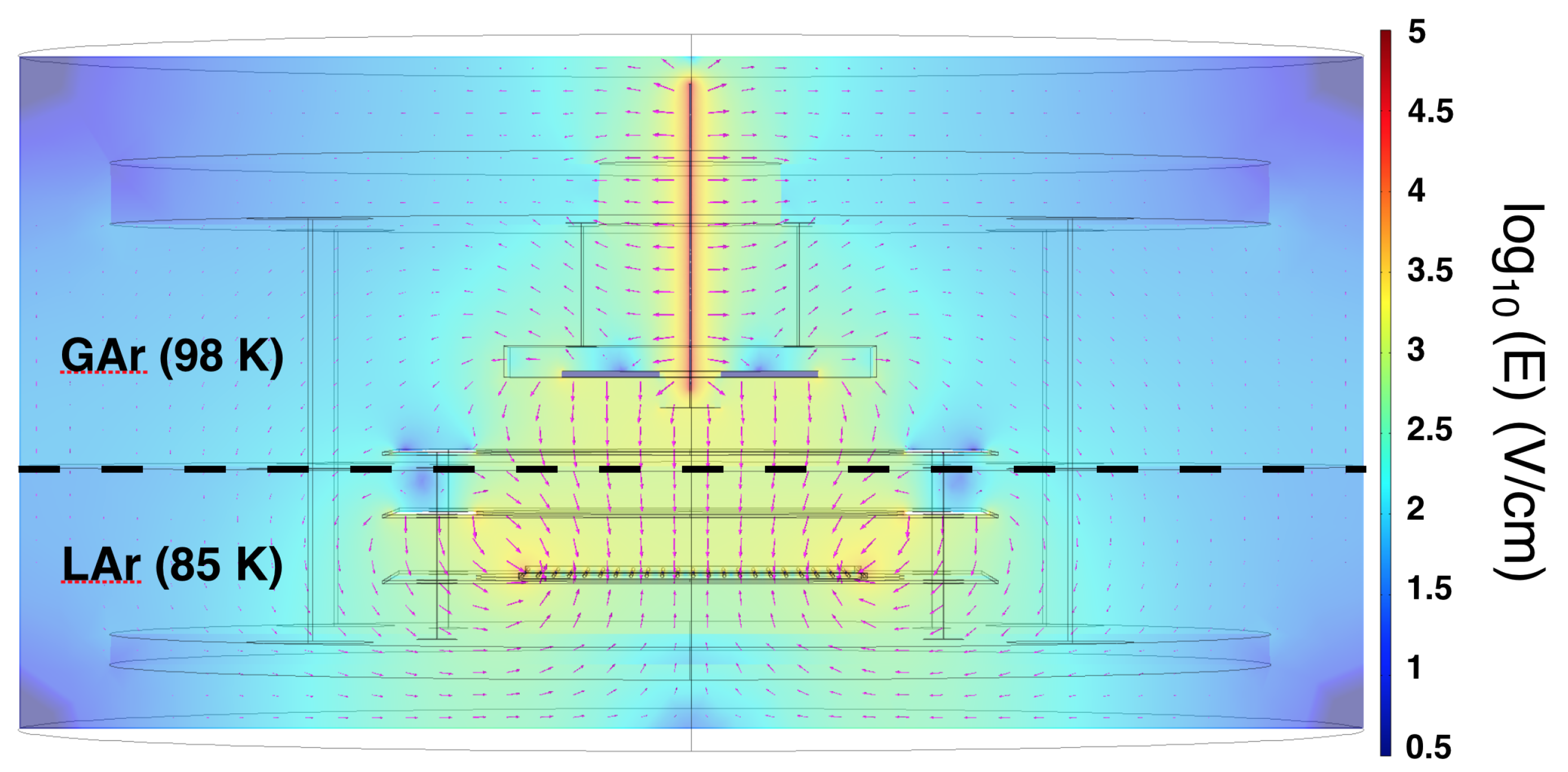
In the simulation, the voltage configuration is set to 3 kV at the anode, −3 kV at the cathode, −1 kV at the top shaping ring (T-SR), and −1.5 kV at the bottom shaping ring (B-SR). The plane (P) around the needle is set to 1 kV. The argon gas dielectric constants at 293 K (1.0005) and 98 K (1.0016) are alike, and the electric field behaviour is similar in both cases.
The electric field map obtained from the simulation, using a similar voltage configuration as in the actual experiment, is depicted in
Figure 2. The liquid argon level is set between the top and bottom shaping rings. In this study, temperatures of 85 K and 98 K are used for liquid and gas argon, respectively. The temperature gradient is assumed to be small in the charge transport region. We observe that, with the voltage settings selected for the experiment, the electric field is uniform in the drift region and most of the field lines starting at the anode terminate at the wires of the cathode.
3. Study of the Ion Feedback from Gas to Liquid
We use the ARION experiment to test different voltage configurations to maximize the charge transfer between the needle (anode) and the wire plane (cathode).
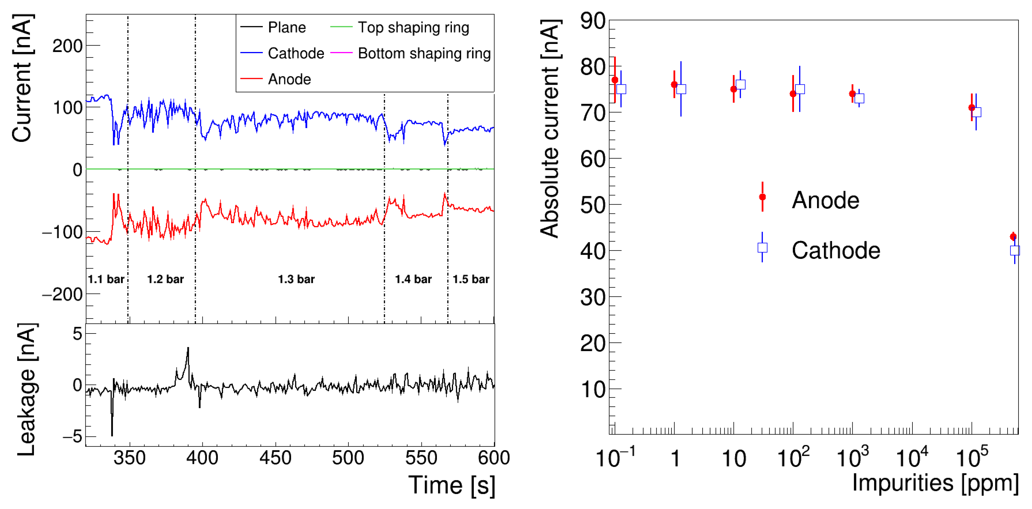
The optimal voltage configuration used for the measurements in this section is as follows: 2 kV on the anode, −3 kV on the cathode, 0.5 kV on the plane around the needle, and 0.7 kV and 0 kV on the T-SR and B-SR, respectively. The currents are measured in the setup parts expected to collect or produce a charge, utilizing a digital picoammeter. During the run, the pressure was raised from 1.1 to 1.5 bar in discrete steps, while the argon gas temperature was kept fixed at 293 K.
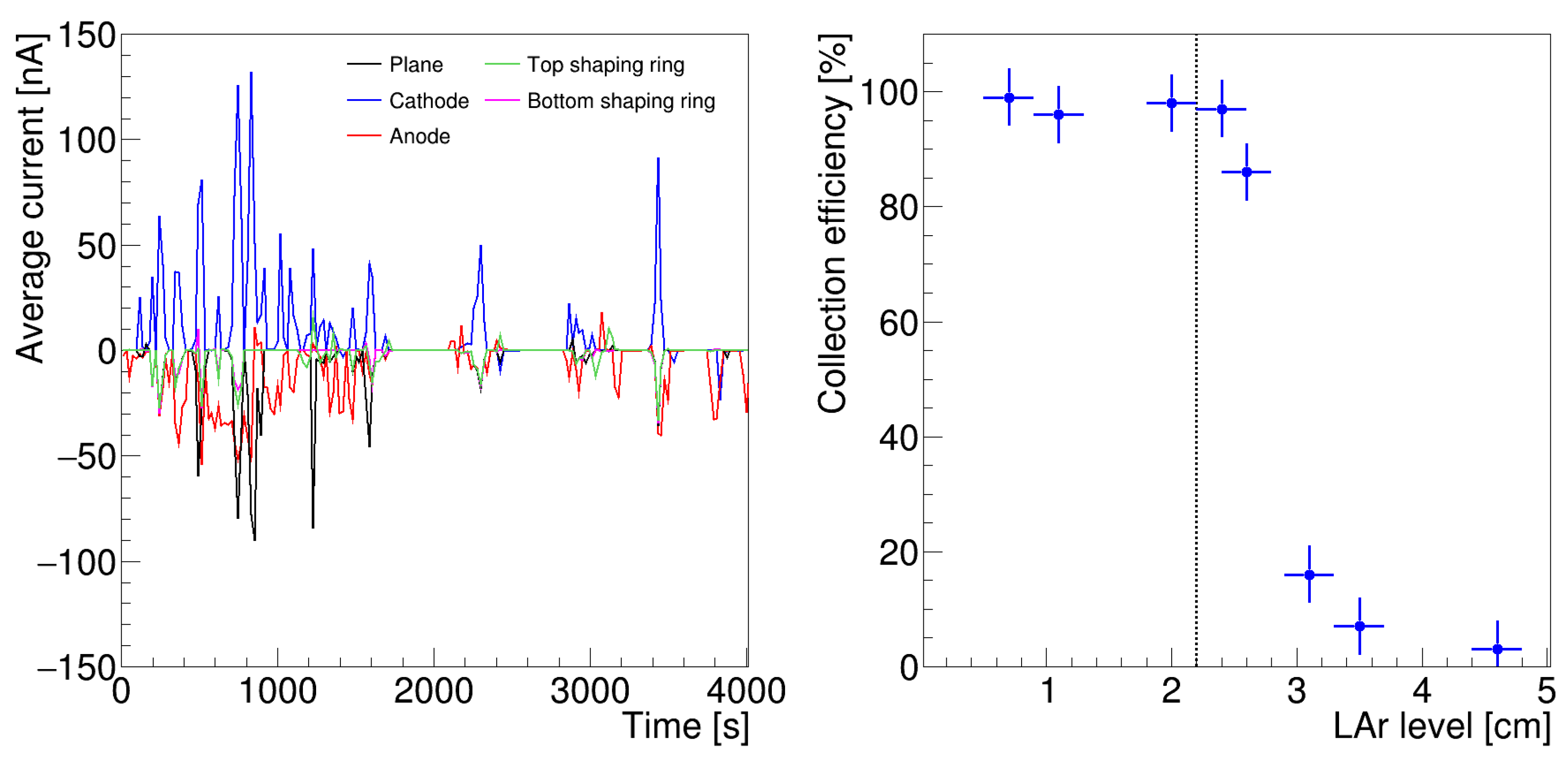
Figure 3 left depicts the time evolution of the registered currents, along with the leakage current, defined as the sum of all the measured currents.
The avalanche at the needle is relatively stable with a measured current of approximately nA. The ions are drifted to the cathode and collected with an efficiency of about 98%, defined as the ratio of the current produced by the anode to that collected. The current detected in the plane around the needle and the two shaping rings is lower than 2 nA. The current produced at the anode decreases when the gas pressure increases. The leakage current remains stable to within 4%. This result demonstrates that the experimental setup is capable of generating a sizeable, stable current between the needle and grid, allowing a study of the space charge and the dynamics of positive ions.
The detector is filled with argon gas from a Standard AirLiquide ALPHAGAZ™-1 bottle, with an approximate purity of 10 ppm. We investigated the impact of argon gas purity on our measurements by comparing different runs with the argon purposely contaminated with defined amounts of air.
Figure 3 right displays the currents at the anode and cathode for different contamination levels at a constant pressure of 1.2 bar, with voltage configuration as described above. The current decreases by less than 4% over the impurities range
,
ppm. Above
ppm, the ion current produced by the Townsend avalanche is highly suppressed due to the higher ionisation energy of the air as compared to argon. These results prove that the impact of gas impurities on the ion drift is negligible.
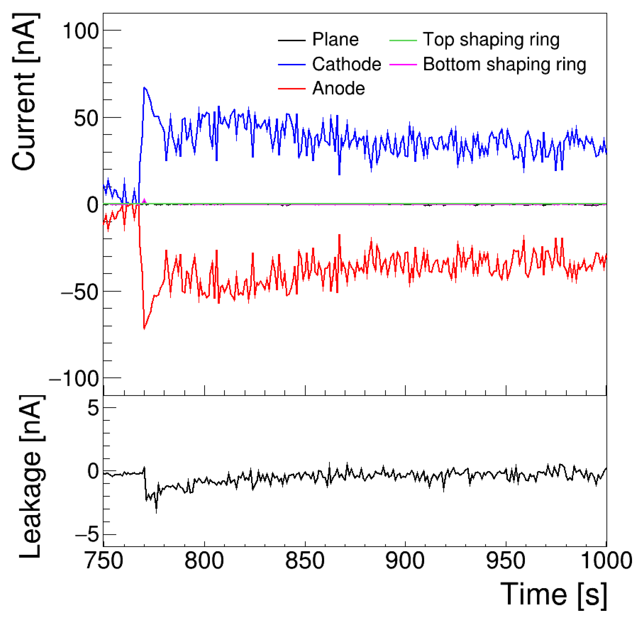
A new set of measurements is performed with the detector filled with gas at 98 K, with the same voltage settings used at room temperature. The measured currents are plotted in
Figure 4. Under these conditions, the magnitude of the ion current produced at the anode is smaller than that measured at room temperature (
Figure 3 left). Since the voltage necessary to produce a continuous current is related to the density of the medium (pressure and temperature), this reduction in current can be explained by the increase in density of the argon gas, which is a factor of 3 higher at cryogenic than at room temperature. In this case, the collection efficiency is close to 98%, comparable to that measured at 293 K. Our measurements demonstrate that it is possible to produce a stable ion stream between the anode and cathode with a collection efficiency close to 100%, both at room and cryogenic temperatures.
To study ion feedback from the gas to liquid phase, data was collected with the chamber filled with liquid argon up to the top shaping ring. The time dependence of the currents is shown in
Figure 5 left. With the cathode covered by 0.5 cm of liquid argon, stable charge transfer between the anode and cathode was not observed, despite applying a voltage to the needle up to 5 kV, much higher than that previously used in gas. Instead, only current peaks were detected, characterised by quickly quenched pulses, indicating a distortion of the electric field between the needle and grid. We attribute this effect to the accumulation of positive charges in the LAr, a consequence of the low mobility of ions in the liquid. To the best of our knowledge, this is the first time space charge effects are observed and studied with a small liquid argon detector.
The collection efficiency is depicted in
Figure 5 right for different LAr levels, as measured from the bottom of the chamber. Independent measurements from the two liquid-level sensors are in good agreement during the initial filling. However, the high precision parallel-plane level sensor did not give reliable data for the remainder of the run. The surface of the gas–liquid interface is not perfectly flat, as bubbling in liquid argon induces roughness in the liquid-level. The sizes of these irregularities are smaller than the sensitivity of the cylindrical level meter (0.2 cm). Thus, the uncertainty on the liquid level is given by the uncertainty of this sensor.
Similar to the results of the previous tests in cold/warm gas, the collection efficiency is close to 100% with the cathode not covered by LAr, while it decreases steeply with the cathode in liquid. A sizeable ion current is measured with the cathode completely submerged in LAr, proving experimentally, for the first time, the possibility for the ions produced in gas to enter the liquid, contrary to the assumption that the ions cannot enter the liquid because of the electrostatic potential problem [
16] and only accumulate on the surface. This result is in agreement with the model proposed in [
17] for the dynamic of the ions at the gas–liquid interface.
4. Test with Ion Pulses and Preliminary Measurement of the Ion Mobility in Gas Argon
Minor changes are implemented in the experimental setup to measure the ion drift velocity in gas and liquid argon under different field conditions. This section presents the commissioning of the detector with argon gas at room temperature.
A constant voltage near ground is applied to the anode, while a negative voltage is applied to the cathode. Positive high-voltage (HV) pulses are generated using a custom-made electrical circuit [
18] connected to the anode via a capacitor. This configuration produces a constant electric field in the drift region and allows ion bunches to be generated in a controlled manner each time a high voltage pulse is triggered. A 1 MHz oscilloscope is used to record the HV pulse (attenuated by a factor 1000) and the signal collected at the cathode.
Under the influence of a constant electric field, the ion cloud produced by the HV pulse drifts from the needle towards the cathode. For an electric field
, the mobility of the ions is given by:
where
is the ion drift velocity,
mm is the distance between anode and cathode and
is the time necessary for the ion cloud to travel this distance. The signal from the cathode is not produced sharply at the arrival time of the ions, rather it is induced as the packet travels along its path according to the Shockley–Ramo theorem [
19,
20]:
where
i is the instantaneous electric current induced on the cathode,
q is the value of the charge packet,
v is the velocity of the packet, and
is the component of the reduced field along the direction of the packet velocity.
According to Equation (
3), ions moving at a low speed induce a tiny signal on the cathode. This signal is produced throughout the transit time of the ions in a constant electric field, making it difficult to measure the precise arrival time of the ions. This issue can be improved by replacing the wire plane with a double coplanar grid, in which one of the two grids serves as the cathode,
K, and is imbricated on a second grid, known as the Frisch grid [
21],
G, which works as an induction plane and provides a high electric field. Both grids are at different potentials, with a higher voltage on the cathode (
) than on the amplification grid (
). Assuming the needle is at ground potential, the drift voltage is
and the amplification voltage
. The significantly higher potential of
compared to
makes the
G grid transparent to drifting ions, with the charge collected only on the cathode.
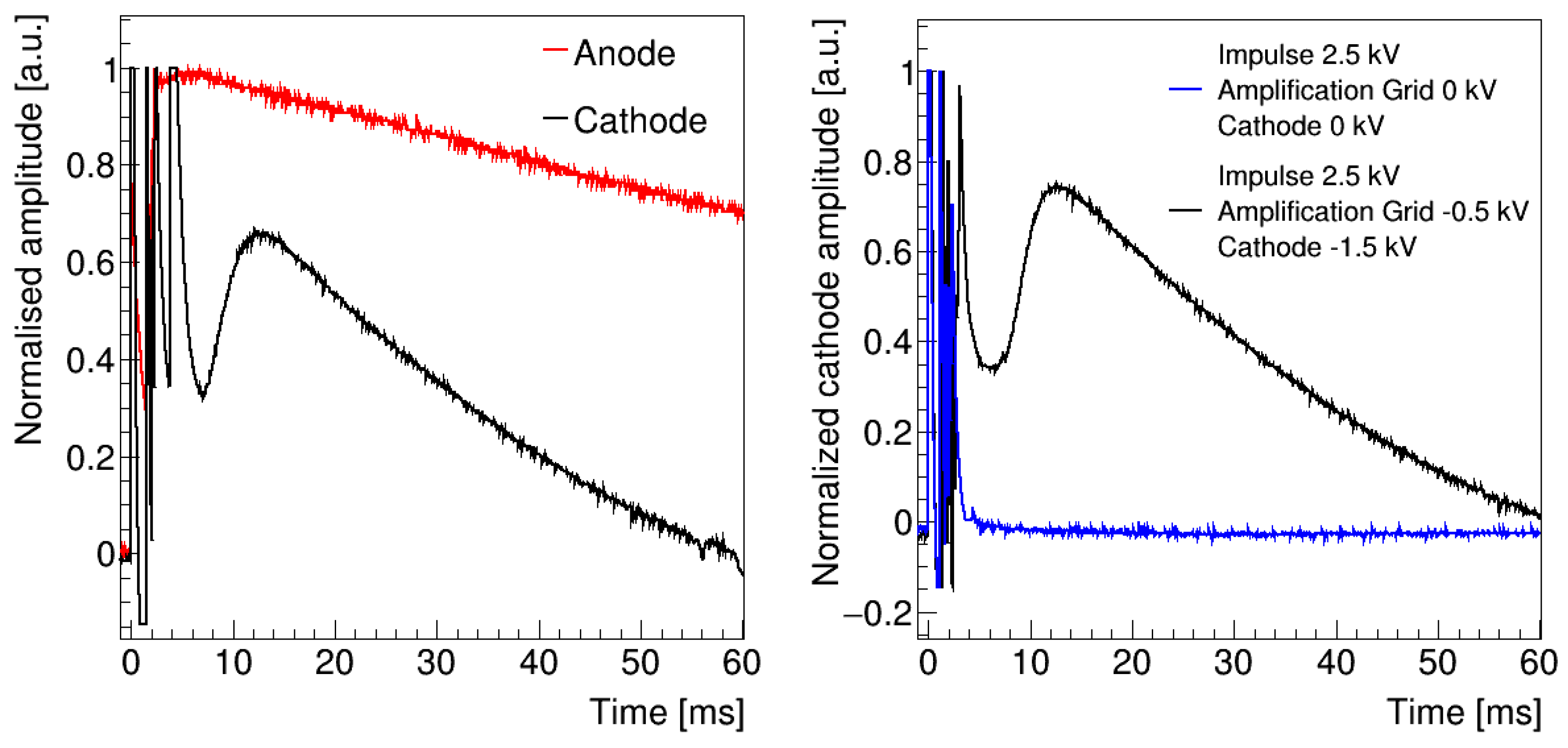
The average signal over 10 pulses with argon gas at room temperature is shown in
Figure 6 left with argon gas at room temperature at 1.4 bar. The anode is fed with a 2.5 kV pulse, the amplification grid is set to −1 kV, and the cathode to −2 kV. The anode signal rises quickly and discharges with a time constant of several tens of milliseconds. A correlated signal is measured at the cathode, in which two regions are differentiated. The first region contains several peaks with a time difference to the anode maximum peak time,
, shorter than 8 ms. A possible explanation for these peaks is the oscillation in the cathode of the electromagnetic signal produced by the avalanche on the needle and picked up by the wires. The second region is formed by a single bump with
larger than 10 ms.
Figure 6 right illustrates the average pulse at the cathode with
kV and the cathode at ground (
). When the drift field is removed, the slow component of the signal disappears and only fast pulses associated with electron induction signals are detected. Furthermore, the time position of the bump observed in the signal at the cathode changes when the values of the electric field or pressure are modified. We therefore conclude that the observed bump corresponds to the positively charged cloud generated at the needle.
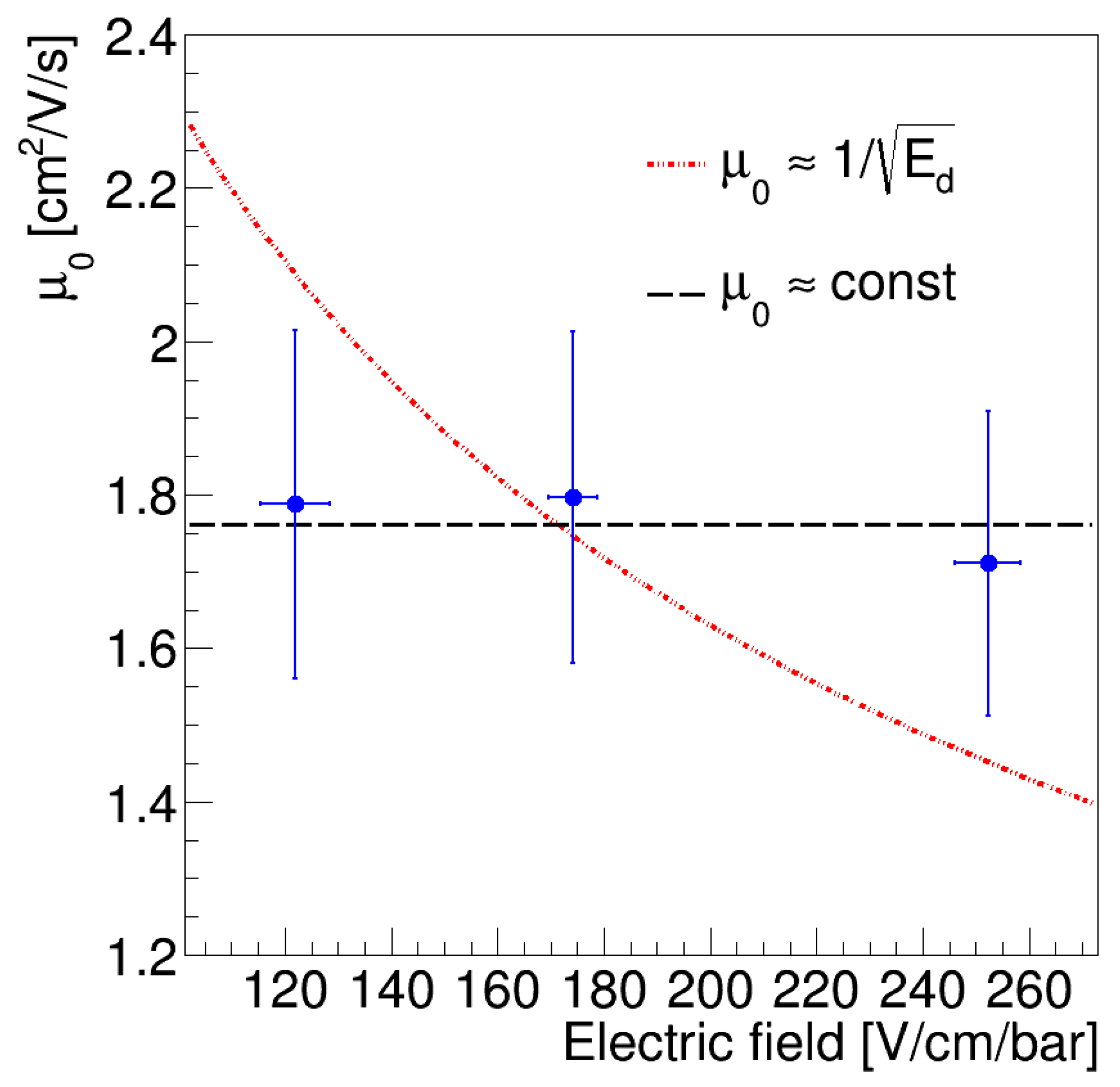
Figure 7 depicts the ion mobility in argon gas in the range [1.1–1.4] bar, calculated by averaging over 10 pulses. The analog manometer introduces an uncertainty of 0.2 bar on the pressure measurement. Ion mobility values in the range [1.8–1.7]
are measured for drift fieldThe abstract has been rewritten between 120 and 260
. The statistical uncertainty is considered for each point. These values are similar to the ones obtained previously in [
22,
23], confirming the capability of the ARION experiment to measure the ion drift velocity. The variation of the ion mobility with the drift field is described in two different models. The first one assumes a constant relation, as expected for low electric fields [
22,
24], and the second model considers a dependence of the form
, as suggested for high electric fields in [
25].
Figure 7 shows that the data are best described by the low electric field model.
An electric field is considered low if the energy gained by an ion in the field is much smaller than the thermal energy. Considering pure argon this is equivalent to [
26]:
where
e is the electron charge,
k the Boltzmann constant,
T the temperature of the gas (293 K), and
ℓ the mean free path between collisions, with a value of 49 nm in pure argon at 1.4 bar [
27]. Using these values, we obtain
2 kV/cm, thus the low-field approximation is valid in the range of operating electric fields studied in this paper. We have therefore demonstrated the ability of the ARION setup to accurately detect ion pulses and measure the drift velocity of the ion packet.
5. Conclusions
The significantly lower drift velocity of positive ions, compared to that of electrons, can induce an sizeable positive charge density in an LAr detector. A resulting volume charge would modify the drift field and quench the negative charge signal. In the case of dual-phase detectors with charge amplification, the positive charge density can be further increased by the ion feedback from the gas to the liquid phase. This effect may be particularly relevant for the next generation of massive argon detectors for dark matter searches and neutrino studies, establishing an intrinsic limit to the technology and reducing the maximum electron drift distance attainable even in the presence of infinite liquid purity.
With the aim of studying the dynamics of positive ions in liquid argon, we have constructed a small detector (1 L) capable of generating, drifting and collecting sizeable positive charge currents. Our setup has been successfully operated to obtain the first evidence of ion feedback from the gas to liquid phase using a continuous ion current. The detector has been successfully run with argon gas at room temperature using ion pulses generated in a controlled manner. Under these conditions, the ion mobility has been measured to be in the range [1.8–1.7] for drift fields between 120 and 260 . Additionally, we have shown that the ion mobility does not depend on the electric drift field. Additional measurements with liquid argon will be reported in a future publication.
