Article

Spin Foam Vertex Amplitudes on Quantum Computer—Preliminary Results

by
Jakub Mielczarek
1,2
1
CPT, Aix-Marseille Université, Université de Toulon, CNRS, F-13288 Marseille, France
2
Institute of Physics, Jagiellonian University, ojasiewicza 11, 30-348 Cracow, Poland
Universe 2019, 5(8), 179; https://doi.org/10.3390/universe5080179
Submission received: 16 April 2019 / Revised: 22 July 2019 / Accepted: 24 July 2019 / Published: 26 July 2019
(This article belongs to the Special Issue Progress in Group Field Theory and Related Quantum Gravity Formalisms)

Abstract

:
Vertex amplitudes are elementary contributions to the transition amplitudes in the spin foam models of quantum gravity. The purpose of this article is to make the first step towards computing vertex amplitudes with the use of quantum algorithms. In our studies we are focused on a vertex amplitude of 3+1 D gravity, associated with a pentagram spin network. Furthermore, all spin labels of the spin network are assumed to be equal j = 1 / 2 , which is crucial for the introduction of the intertwiner qubits. A procedure of determining modulus squares of vertex amplitudes on universal quantum computers is proposed. Utility of the approach is tested with the use of: IBM’s ibmqx4 5-qubit quantum computer, simulator of quantum computer provided by the same company and QX quantum computer simulator. Finally, values of the vertex probability are determined employing both the QX and the IBM simulators with 20-qubit quantum register and compared with analytical predictions.

1. Introduction

The basic objective of theories of quantum gravity is to calculate transition amplitudes between configurations of the gravitational field. The most straightforward approach to the problem is provided by the Feynman’s path integral
Ψ f | Ψ i = D [ g ] D [ ϕ ] e i ( S G + S ϕ ) ,
where S G and S ϕ are the gravitational and matter actions respectively. While the formula (1) is easy to write, it is not very practical for the case of continuous gravitational field, characterized by infinite number of degrees of freedom. One of the approaches to determine (1) utilizes discretization of the gravitational field associated with some cut-off scale. The expectation is that continuous limit of such discretized theory can be recovered at the second order phase transition [1,2]. The essential step in this challenge is to generate different discrete space-time configurations (triangulations) contributing to the path integral (1). In Causal Dynamical Triangulations (CDT) [1] which is one of the approaches to the problem, Markov chain of elementary moves is used to explore different triangulations between initial and final state. In practice, the Markov chain is implemented after performing Wick rotation in Equation (1). In the last 20 years, the procedure has been extensively studied running computer simulations [3]. However, in 1+1 D case analytical methods of generating allowed triangulations are also available. In particular, it has been shown that Feynman diagrams of auxiliary random matrix theories generate graphs dual to the triangulations [4]. An advantage of the method is that in the large N (color) limit of such theories, symmetry factors associated with given triangulations can be recovered [5].
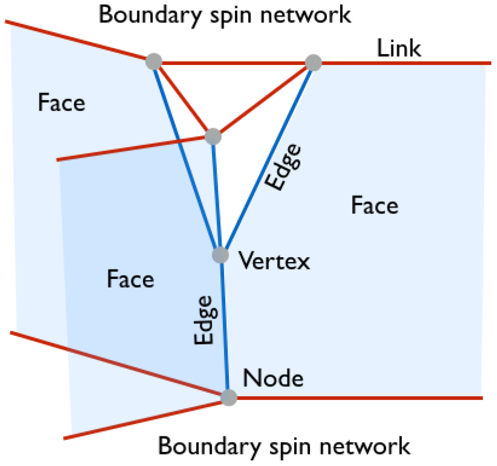
Another path to the problem of determining (1) is provided by the Loop Quantum Gravity (LQG) [6,7] approach to the Planck scale physics. Here, discreteness of space is not due to the applied by hand cut-off but is a consequence of the procedure of quantization. Accordingly, the spatial configuration of the gravitational is encoded in the so-called spin network states [8]. In consequence, the transition amplitude (1) is calculated between two spin network states. The geometric structures (2-complexes) representing the path integral are called Spin Foams [9,10]. The elementary processes contributing to the spin foam amplitudes are associated with vertices of the spin foams and are called vertex amplitudes [11,12]. The employed terminology of spin networks and spin foams is clarified in Figure 1 in an example of 2+1 D gravity.
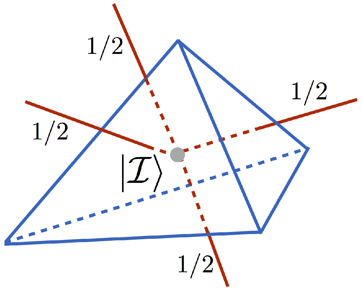
In Figure 1 two boundary spin networks with 3-valent nodes are shown. Such nodes are dual to two-dimensional triangles. In this article we will focus on the 3+1 D case in which the spin network nodes (related with non-vanishing volumes) are 4-valent. The nodes are dual to tetrahedra (3-simplex). In the example presented in Figure 1, the four edges of the 2-complex meet at the vertex. However, in the 3+1 D case the valence of the vertex is higher and equal to 5. For the purpose of this article it is crucial to note that such 5-valent vertices can be enclosed by a boundary represented by a spin network containing five nodes. Each of the nodes is placed on one of the five edges entering the vertex. The boundary has topology of a three-sphere, S 3 . This is higher dimensional extension of the 2+1 D case, where a vertex can be enclosed by the two-sphere, S 2 .
In analogy to the random matrix theories in case of the 2D triangulations, the spin foams (2-complexes) can also be obtained as Feynman diagrams of some auxiliary field theory. Namely, the so-called Group Field Theories (GFTs) have been introduced to generate structure of vertices and edges associated with spin foams [13,14,15]. In particular, the 3+1 D theory with 5-valent vertices requires GFT with five-order interaction terms, known as Ooguri’s model [16]. There has recently been great progress in the field of GFTs with many interesting results (see e.g., [17,18]).
The aim of this article is to investigate a possibility of employing universal quantum computers to compute vertex amplitudes of 3+1 D spin foams. The idea has been suggested in Ref. [19], however, it is not investigated there. Here, we make the first attempt to materialize this concept. In our studies, we consider a special case of spin networks with spin labels corresponding to fundamental representations of the S U ( 2 ) group, for which intertwiner qubits [19,20,21] can be introduced. The qubits will be implemented on IBM Q 5-qubit quantum computer (ibmqx4) as well as with the use of quantum computer simulator provided by the same company [22]. In the case of real 5-qubit quantum computer the qubits are physically realized as superconducting circuits [23] operating at millikelvin temperatures. Furthermore, the QX quantum computer simulator [24], available on the Quantum Inspire [25] platform, will be employed.
The studies contribute to our broader research program focused on exploring the possibility of simulating Planck scale physics with the use of quantum computers. The research is in the spirit of the original Feynman’s idea [26] of performing the so-called exact simulations of quantum systems with the use of quantum information processing devices. In our previous articles [21,27] we have preliminary explored the possibility of utilizing Adiabatic Quantum Computers [28] to simulate quantum gravitational systems. Here, we are making the first steps towards the application of Universal Quantum Computers [29,30].

2. Intertwiner Qubit

The basic question a skeptic can ask is why it is worth considering quantum computers to study Planck scale physics at all? Can we not just do it employing classical supercomputers as in the case of CDT approach to quantum gravity? Let me answer these questions by giving two arguments. The first concerns the huge dimensionality of a Hilbert space for many-body quantum system. For a single spin-1/2 (qubit) Hilbert space H 1 / 2 = span { | 0 , | 1 } the dimension is equal to 2. However, considering N such spins (qubits) the resulting Hilbert space is a tensor product of N copies of the qubit Hilbert space. The dimension of such space grows exponentially with N:
dim ( H 1 / 2 H 1 / 2 H 1 / 2 N ) = 2 N .
This exponential behavior is the main obstacle behind simulating quantum systems on classical computers. With the present most powerful classical supercomputers we can simulate quantum systems with N = 64 at most [31]. The difficulty is due to the fact that quantum operators acting on 2 N dimensional Hilbert space are represented by 2 N × 2 N matrices. Operating with such matrices for N > 50 is challenging to the currently available supercomputers. On the other hand, such companies as IBM or Rigetti Computing are developing quantum chips with N > 100 and certain topologies of couplings between the qubits. The possibility of simulating quantum systems which are unattainable to classical supercomputers may, therefore, emerge in the coming decade leading to the so-called quantum supremacy [32]. See Appendix A for more detailed discussion of the state of the art of the quantum computing technologies and prospects for the near future. The second argument concerns quantum speed-up leading to reduction of computational complexity of some classical problems. Such possibility is provided by certain quantum algorithms (e.g., Deutsch, Grover, Shor, …) thanks to the so-called quantum parallelism. For more information on quantum algorithms please see Appendix B, where elementary introduction to quantum computing can be found.
Taking the above arguments into account we are convinced that it is justified to explore the possibility of simulating quantum gravitational physics on quantum computers. The fundamental question is, however, whether gravitational degrees of freedom can be expressed with qubits, which are used in the current implementations of quantum computers1. Fortunately, it has recently been shown that at least in Loop Quantum Gravity approach to quantum gravity notion of qubit degrees of freedom can be introduced and is associated with the intertwiner space of a certain class of spin networks (see Refs. [19,20,21,27]).
Let us briefly explain it. Namely, nodes of the spin networks are where Hilbert spaces associated with the links meet. The gauge invariance (enforced by the Gauss constraint) implies that the total spin at the node has to be equal zero. The 4-valent nodes are of special interest since they are associated with the non-vanishing eigenvalues of the volume operator (see e.g., Ref. [7]). As already mentioned in the introduction, in the picture of discrete geometry, the 4-valent nodes are dual to tetrahedra. The class of spin networks that we are focused on here are those with links of the spin networks labelled by fundamental representations of the S U ( 2 ) group (i.e., the spin labels are equal j = 1 / 2 ) and the nodes are 4-valent. For such spin networks the Hilbert spaces at the nodes are given by the following tensor products:
H 1 / 2 H 1 / 2 H 1 / 2 H 1 / 2 = 2 H 0 3 H 1 H 2 .
The Gauss constraint implies that only singlet configurations ( H 0 ) are allowed. Because there are two copies of the spin-zero configurations in the tensor product (3), the so-called intertwiner Hilbert space is two-dimensional:
dim Inv ( H 1 / 2 H 1 / 2 H 1 / 2 H 1 / 2 ) = 2 .
We associate the two-dimensional invariant subspace with the intertwiner qubit | I H 0 H 0 . The 4-valent node (at which the intertwiner qubit is defined) together with the entering links is dual to the tetrahedron in a way shown in Figure 2.
The two basis states of the intertwiner qubit | I are basically the two singlets we can obtain for a system of four spins 1 / 2 . The basis states can be expressed composing familiar singlets and triplet states for two spin-1/2 particles:
| S = 1 2 | 01 | 10 ,
| T + = | 00 ,
| T 0 = 1 2 | 01 + | 10 ,
| T = | 11 .
Namely, in the s-channel (which is one of the possible superpositions) the intertwiner qubit basis states can be expressed as follows:
| 0 s = | S | S ,
| 1 s = 1 3 | T + | T + | T | T + | T 0 | T 0 .
The | 0 s state is simply a tensor product of two singlets for two spin-1/2 particles, while the state | 1 s does not have such a simple product structure. The states | 0 s and | 1 s form an orthonormal basis of the intertwiner qubit. Worth stressing is that other bases being linear superpositions of | 0 s and | 1 s might be considered. In particular, the eigenbasis of the volume operator turns out to be useful (see Ref. [27]). Here we stick to the s-channel basis { | 0 s , | 1 s } in which a general intertwiner state (neglecting the total phase) can be expressed as
| I = cos ( θ / 2 ) | 0 s + e i ϕ sin ( θ / 2 ) | 1 s ,
where θ [ 0 , π ] and ϕ [ 0 , 2 π ) are angles parametrizing the Bloch sphere.
In the context of quantum computations it is crucial to define a quantum algorithm (a unitary operation U ^ I acting on the input state) which will allow us to create the intertwiner state (11) from the input state | 0000 , i.e.,
| I = U ^ I | 0000 .
The general construction of the operator U ^ I can be performed applying the procedure introduced in Ref. [33], and will be discussed in a sequel to this article [34]. Here, for the purpose of illustration of the method of computing vertex amplitude we will focus on the special case of the intertwiner states being the first basis state: | I = | 0 s = | S | S . The contributing two-particle singlet states can easily be generated as a sequence of elementary gates used to construct quantum circuits (see also Appendix B):
| S = CNOT ^ ( H ^ I ^ ) ( X ^ X ^ ) | 00 .
Here, the X ^ is the so-called bit-flip (NOT) operator (Pauli σ x matrix) which transforms | 0 into | 1 and | 1 into | 0 (i.e., X ^ | 0 = | 1 and X ^ | 1 = | 0 ). The H ^ is the Hadamard operator defined as H ^ | 0 = 1 2 | 0 + | 1 and H ^ | 1 = 1 2 | 0 | 1 . Finally, the CNOT ^ is the Controlled NOT 2-qubit gate defined as CNOT ^ ( | a | b ) = | a | a b , where a , b { 0 , 1 } and ⊕ is the XOR (exclusive or) logical operation, such that 0 0 = 0 , 0 1 = 1 , 1 0 = 1 and 1 1 = 0 . In consequence, the | 0 s basis state can be expressed as follows:
| 0 s = ( CNOT ^ CNOT ^ ) ( H ^ I ^ H ^ I ^ ) ( X ^ X ^ X ^ X ^ ) | 0000 = 1 2 | 0101 + | 1010 | 0110 | 1001 .
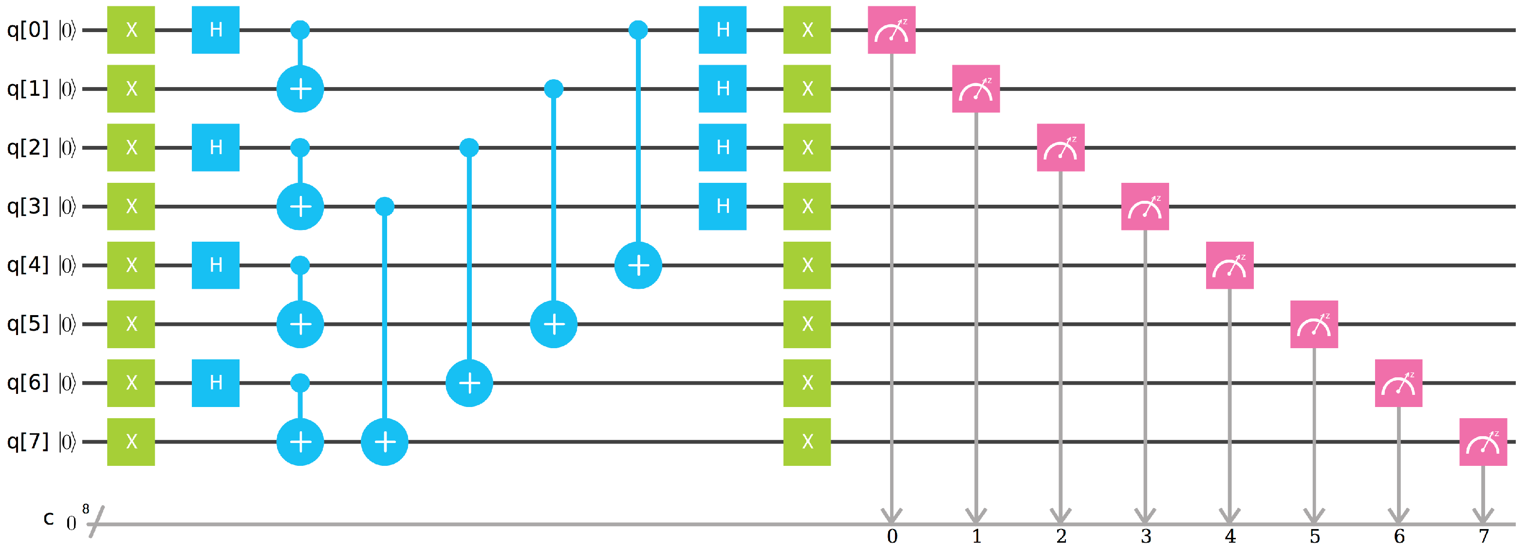
In Figure 3 a quantum circuit generating (and measuring) the intertwiner state | 0 s has been presented.
The final state can be written as a superposition of 16 basis states in the product space of four qubit Hilbert spaces:
| Ψ = i j k l { 0 , 1 } a i j k l | i j k l ,
where the normalization condition implies that i j k l { 0 , 1 } | a i j k l | 2 = 1 .
We have executed the quantum algorithm (14) with the use of both the IBM simulator of quantum computer and the real IBM Q 5-qubit quantum chip ibmqx4. In both cases the algorithm has been executed 1024 times. Moreover, the algorithm (14) has also been executed (1024 times) on the QX quantum computer simulator. Results of the measurements of probabilities P ( i ) = | a i | 2 are summarized in Table 1.
Clearly, the results obtained from the simulator match well with the values predicted in Equation (14). By increasing the number of shots, the accuracy of the results can be improved. In fact, because the number of shots in a single round was limited (either to 8192 in the case of the IBM simulator or to 1024 in the case of the QX simulator) the computational rounds had to be repeated in order to achieve better convergence to theoretical predictions. Furthermore, the results were also verified with the use of two other publicly available quantum simulators of quantum circuits, i.e., Quirk [35] and Q-Kit [36].
On the other hand, the errors of the ibmqx4 quantum processor are more significant, leading even to 10 % contribution from the undesired states, such as | 1101 and | 1110 . The errors have two main sources. The first are instrumental errors associated with uncertainty of gates, uncertainty of initial state preparation and uncertainty of readouts. For the IBM Q ibmqx4 quantum processor the single-qubit gate errors are at the level of 0.001 and the errors of readouts are reaching even 0.086 for some of the qubits. The two-qubit gates are less accurate than the single quibit gates, with the errors approximately equal to 0.035 . The concrete values for every qubit and pairs of qubits are provided via the IBM website [22]. The second source of error is due to statistical nature of quantum mechanics and the limited number of measurements. For a single qubit, the problem of estimating corresponding error is equivalent to the 1D random walk, which leads to uncertainty of the estimation of probability equal s n = p ( 1 p ) n , where n is the number of measurements and p is a probability of one of the two basis states. As an example, for n = 1024 and p = 1 / 2 we obtain s n 0.016 . In the considered case of 16 basis states the uncertainty is expected to be lower roughly by the factor 0.5 2, leading to an approximate error equal 0.008 (the value is smaller because the average number of counts per basis states decreased). Summing up both the instrumental error and the uncertainty of measurement, we may estimate the cumulative uncertainty to be at the level of ∼15%, which is in agreement with the experimental data. With the current setup, the errors can be slightly reduced by increasing the number of measurements and by optimization of the quantum circuit, e.g., by placing (less noisy) single-qubit gates after (more noisy) two-qubit gates. In further studies, the circuits should also be equipped with quantum error correction algorithms. This will, however, require additional qubits to be involved. Moreover, reduction of the instrumental error will be a crucial challenge for the future utility of the quantum processors.
Let us end this section with quantitative comparison of the results from the Table 1 with the use of classical Fidelity (Bhattacharyya distance) F ( q , p ) : = i p i q i , where { p i } and { q i } are two sets of probabilities. Comparison of the theoretical values with the results obtained from the IBM Simulator gives us F 99.9 % . However, comparing the theoretical values with the results of IBM Q ibmqx4 quantum computer we find much smaller Fidelity F 71.4 % . Worth keeping in mind is that the employed Fidelity function concerns classical probabilities and further analysis of the quantum state obtained from the quantum computer should include also analysis of the quantum Fidelity F ( ρ ^ 1 , ρ ^ 2 ) : = tr ρ ^ 1 ρ ^ 2 ρ ^ 1 , where ρ ^ 1 and ρ ^ 2 are density matrices of the compared states [37]. For this purpose (i.e., reconstruction of the density matrix), full tomography of the obtained quantum state has to be performed.

3. Vertex Amplitude

Gravity is a theory of constraints. Specifically, in LQG three types of constraints are involved. The first is the mentioned Gauss constraint, which has already been imposed at the stage of constructing spin networks states. The second is the spatial diffeomorphism constraint which is satisfied by introducing equivalence relation between all spin-networks characterized by the same topology. The third is the so-called scalar or Hamiltonian constraint, which encodes temporal dynamics and is the most difficult to satisfy. In quantum theory, this constraint takes a form of an operator. Let us denote this operator as C ^ . Following the Dirac procedure for constrained quantum systems, the physical states are those belonging to the kernel of the constraints, i.e., C ^ | Ψ = 0 . Due to the complicated form of the gravitational scalar constraint (see e.g., [6]), finding the physical states is in general a difficult task. However, for certain simplified scalar constraints, such as for the symmetry reduced cosmological models, the physical states are possible to extract. Furthermore, it has recently been proposed in Ref. [21] that the problem of solving simple constraints can be implemented on Adiabatic Quantum Computers.
Another approach to the problem of constraints is to consider a projection operator
P ^ : = lim T 1 2 T T T d τ e i τ C ^ ,
which projects kinematical states onto physical subspace. In particular, the Formula (16) is valid for C ^ characterized by discrete spectrum of eigenvalues. Specifically, the projection operator (16) can be used to evaluate transition amplitude between any two kinematical states | x and | x :
W ( x , x ) = x | P ^ | x .
The state | x might correspond to the initial and | x to the final boundary spin network states (confront with Figure 1). While the notion of the boundary initial and final hypersurfaces is well defined in the case with preferred time foliation, the general relativistic case deserves generalization of the transition amplitude to the form being independent of the background time variable. This leads to the concept of boundary formulation [38] of transition amplitudes in which the transition amplitude is a function of boundary state only. Taking the particular boundary physical spin network state | Ψ the transition amplitude can be, therefore, written as
W ( Ψ ) = W | Ψ ,
where the state | Ψ corresponds to representation in which the amplitude is evaluated. Worth stressing at this point is that physical interpretation of the transition amplitude (18) is still under debate. In particular, very little is known about relation of the amplitude with the physical states of the theory under consideration.
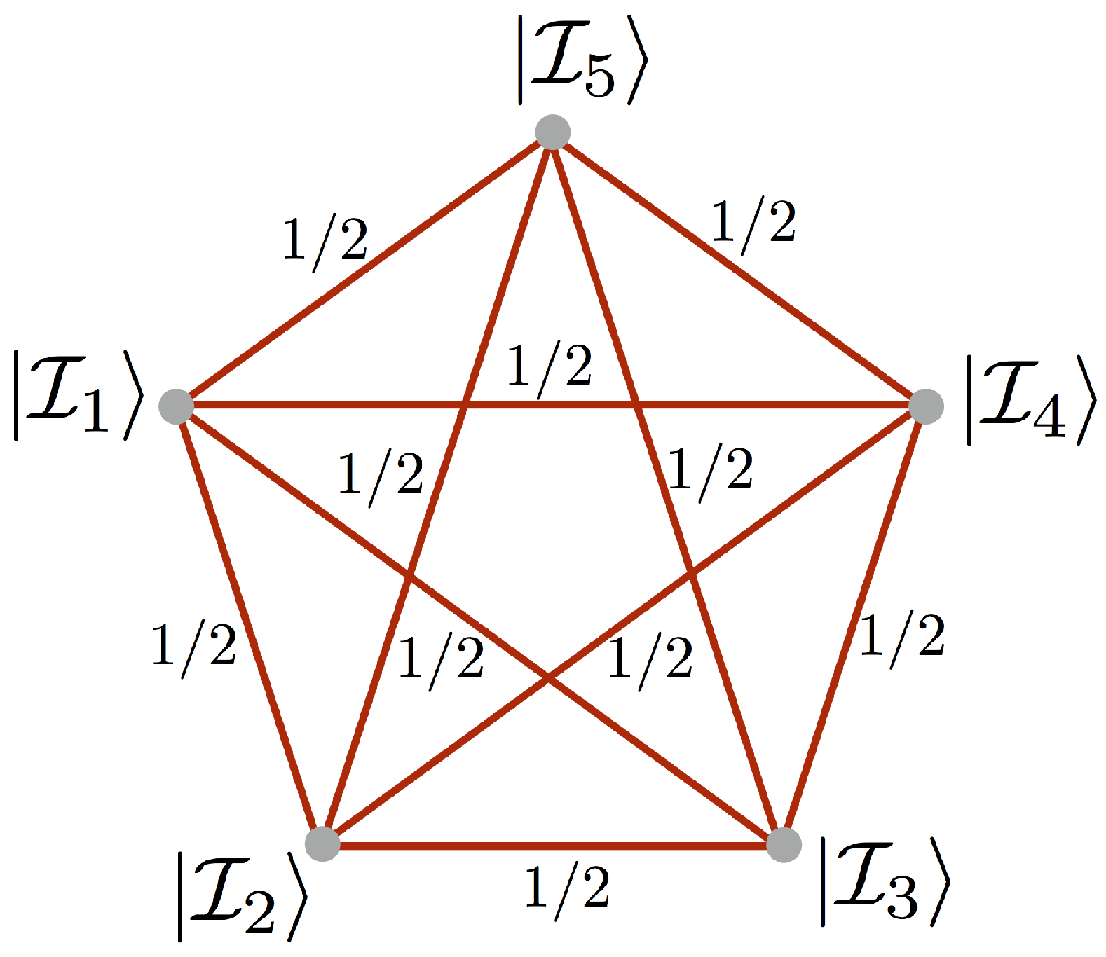
The object of our interest in this article, namely the vertex amplitude, is the amplitude (18) of boundary enclosing a single vertex. As we have already explained in the introduction, the spin network enclosing the single vertex has pentagram structure and can be written as:
W | Ψ = A ( I 1 , I 2 , I 3 , I 4 , I 5 ) .
The associated spin network is shown in Figure 4.
The pentagram spin network state is a tensor product of the five intertwiner qubits:
| Ψ = n = 1 5 | I n .
Since in the vertex amplitude (18) physical states have to be considered the intertwiner qubits | I n have to be selected such that the state is annihilated by the scalar constraint: C ^ | Ψ = 0 . Due to the difficulty of the issue for general form of the scalar constraint operator, we do not address the problem of selecting | Ψ states here. As we have mentioned, for either symmetry reduced or simplified scalar constraints the physical states can be identified with the use of existing methods.
Another issue is the choice of the state | W . Usually the representation of holonomies associated with the links of the spin networks are considered. Here, following Ref. [19] we will evaluate the boundary spin network state in the state:
| W = l = 1 10 | E l ,
where
| E l = 1 2 | 01 | 10
are Bell states associated with the links. This choice is interesting since the Bell states introduce entanglement between faces of the adjacent tetrahedra. Such a way of “gluing” tetrahedra by quantum entanglement has been recently studied in Ref. [39], where it was shown that the | W state is a superposition of spin network states (with { 15 j } symbols as coefficients of the decomposition). Since the spin network state | Ψ is disentangled one can also interpret W | Ψ as an amplitude of transition between disentangled and maximally entangled piece of quantum geometry. Going further, possibly the quantum entanglement is the key ingredient which merges the chunks of space associated with the nodes of spin networks into a geometric structure. This reasoning is consistent with the recent advances in the domain of entanglement/gravity duality, an example of which is provided by the AdS/CFT correspondence [40], ER = EPR conjecture [41] and considerations of holographic entanglement entropy [42,43,44]. Interestingly, it has recently been argued that indeed the spin networks may represent structure of quantum entanglement [45], indicating relation between spin networks and tensor networks [46]. This is actually not very surprising since the holonomies associated with links of the spin-networks can be interpreted as “mediators” of entanglement.
Namely, the holonomies are maps between two vector (Hilbert) spaces at the ends of a curve e ( λ ) , where the affine parameter λ [ 0 , 1 ] . Let us denote the initial point as a = e ( 0 ) and the final one as b = e ( 1 ) . Then, holonomy h e is a map between two Hilbert spaces H ( a ) and H ( b ) associated with two (in general) different spatial locations:
h e : H ( a ) H ( b ) .
In the case considered in this article, the Hilbert spaces are related with the elementary qubits H 1 / 2 “living” at the ends of the links of the spin-networks (keep in mind that these are not the intertwiner qubits but the elementary qubits out of which the intertwiner qubits are built). As an example of the holonomy of the Ashtekar connection A considered in LQG (i.e., h e : = P exp e A , see e.g., Ref. [6]) let us consider
h x ( α ) : = e i σ x α = I cos ( α ) + i σ x sin ( α ) ,
where α is an angle variable and σ x is the Pauli matrix. The holonomies as the one given by Equation (24) are associated with homogeneous models and are considered in Loop Quantum Cosmology [47] and Spinfoam Cosmology [48,49]. The special case is when α = π / 2 for which h x ( π / 2 ) = i σ x , which written as an operator
h ^ x ( π / 2 ) = i X ^ ,
where X ^ is the bit-flip operator introduced earlier. Therefore, having, e.g., the elementary qubit | 0 H 1 / 2 ( a ) at point a, the operator (25) maps this state into h ^ x ( π / 2 ) | 0 = i X ^ | 0 = i | 1 H 1 / 2 ( b ) at the point b3. This introduces a relation between the quantum states at distant points a and b, which possibly can be associated with entanglement. However, the issue of relation between holonomies and entanglement requires further more detailed studies, also in the spirit of the recent proposal of Entanglement holonomies [50].

4. A Quantum Algorithm

Having the vertex amplitude (19) defined we may proceed to the task of determining | W | Ψ | 2 with the use of quantum computers. Here, we will show how to obtain amplitude modulus square (the probability), while extraction of the phase factor will be a subject of our further investigations.
Let us begin with preparation of a suitable quantum register. Because each of the intertwiner qubits is a superposition of four elementary qubits, evaluation of the spin network with N nodes requires 4 N qubits in the quantum register4. The corresponding Hilbert space is spanned by 2 4 N basis states | i , where i 0 , , 2 4 N 1 . The initial state for the quantum algorithm is:
| 0 = | 0 | 0 4 N .
Now, we have to find unitary operators U ^ Ψ and U ^ W defined such that
| Ψ = U ^ Ψ | 0 ,
| W = U ^ W | 0 ,
where | 0 is given by Equation (26). Utilizing the operators U ^ Ψ and U ^ W we introduce an operator U ^ : = U ^ W U ^ Ψ . Action of this operator on the initial state (26) can be expressed as a superposition of the basis states with some amplitudes a i C :
U ^ | 0 = i = 0 2 4 N 1 a i | i .
It is now easy to show that the a 0 coefficient in this superposition is the transition amplitude we are looking for. Namely:
a 0 = 0 | U ^ | 0 = 0 | U ^ W U ^ Ψ | 0 = W | Ψ .
By performing measurements on the final state we find the probabilities P ( i ) = | a i | 2 . The first of these probabilities is the modulus square of the vertex amplitude.
Before we will proceed to the discussion of the pentagram spin network associated with the vertex amplitude, let us first demonstrate the algorithm on two simpler examples of spin networks with one and two nodes.

4.1. Example 1—Single Tetrahedron

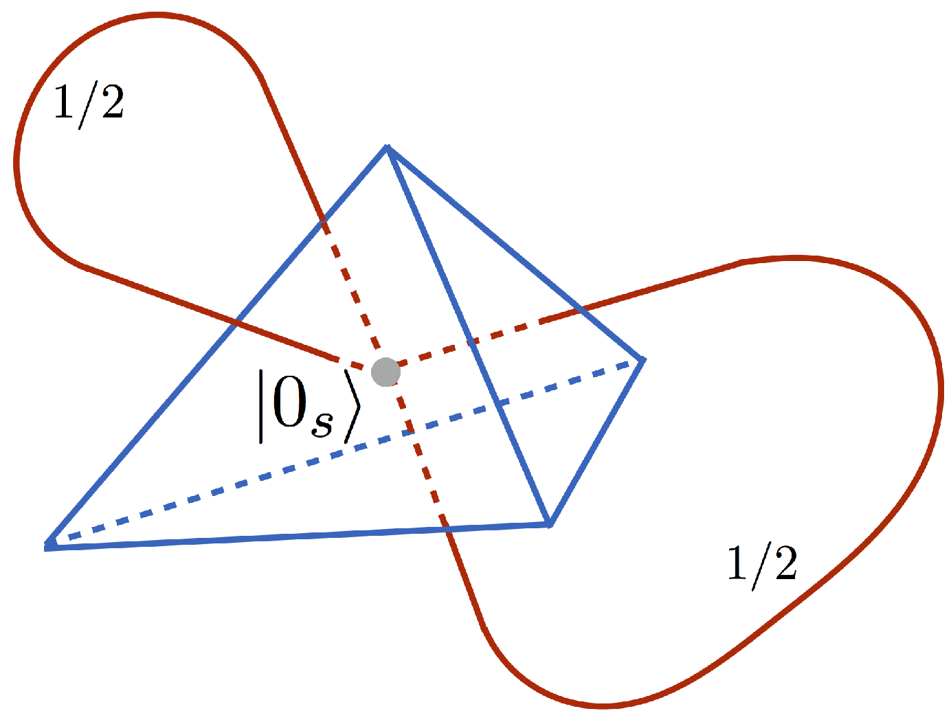
As a first example let us consider the case of a single-node spin network presented in Figure 5.
Here, the intertwiner qubit is in the | Ψ = | 0 s state composed out of the four elementary qubits according to Equation (14). The representation state | W is a tensor product of two Bell states (22). There are basically two different choices of pairing faces of the tetrahedron. The first choice is according to the pairing of qubits entering to the two-qubit singlets | S out of which the | 0 s state is built. The second choice is by linking qubits contributing to the two different singlets. The first choice is trivial since in that case U ^ W = U ^ Ψ and in consequence the amplitude W | Ψ = 0 | U ^ W U ^ Ψ | 0 = 0 | 0 = 1 . Therefore, we will consider the second case for which the quantum circuit associated with the U ^ = U ^ W U ^ Ψ operator is presented in Figure 6.
The simulations were performed on both the IBM simulator and the QX simulator, with 1024 shots in each computational round. The rounds have been repeated 10 times. The results obtained are collected in Table 2.
Averaging over the 10 rounds, the following values of modulus square of the amplitudes are obtained:
| W | Ψ | 2 = | a 0 | 2 = c c 0.252 ± 0.009 for QX simulator 0.256 ± 0.014 for IBM simulator .
The results are consistent with the theoretically expected value | a 0 | 2 = 0 . 25 . Finally, worth mentioning is that the algorithm cannot directly be executed using the IBM Q 5-qubit quantum chip due to the topological constraints of the structure of coupling between qubits. Additional ancilla qubits have to be involved for this purpose.

4.2. Example 2—Two Tetrahedra

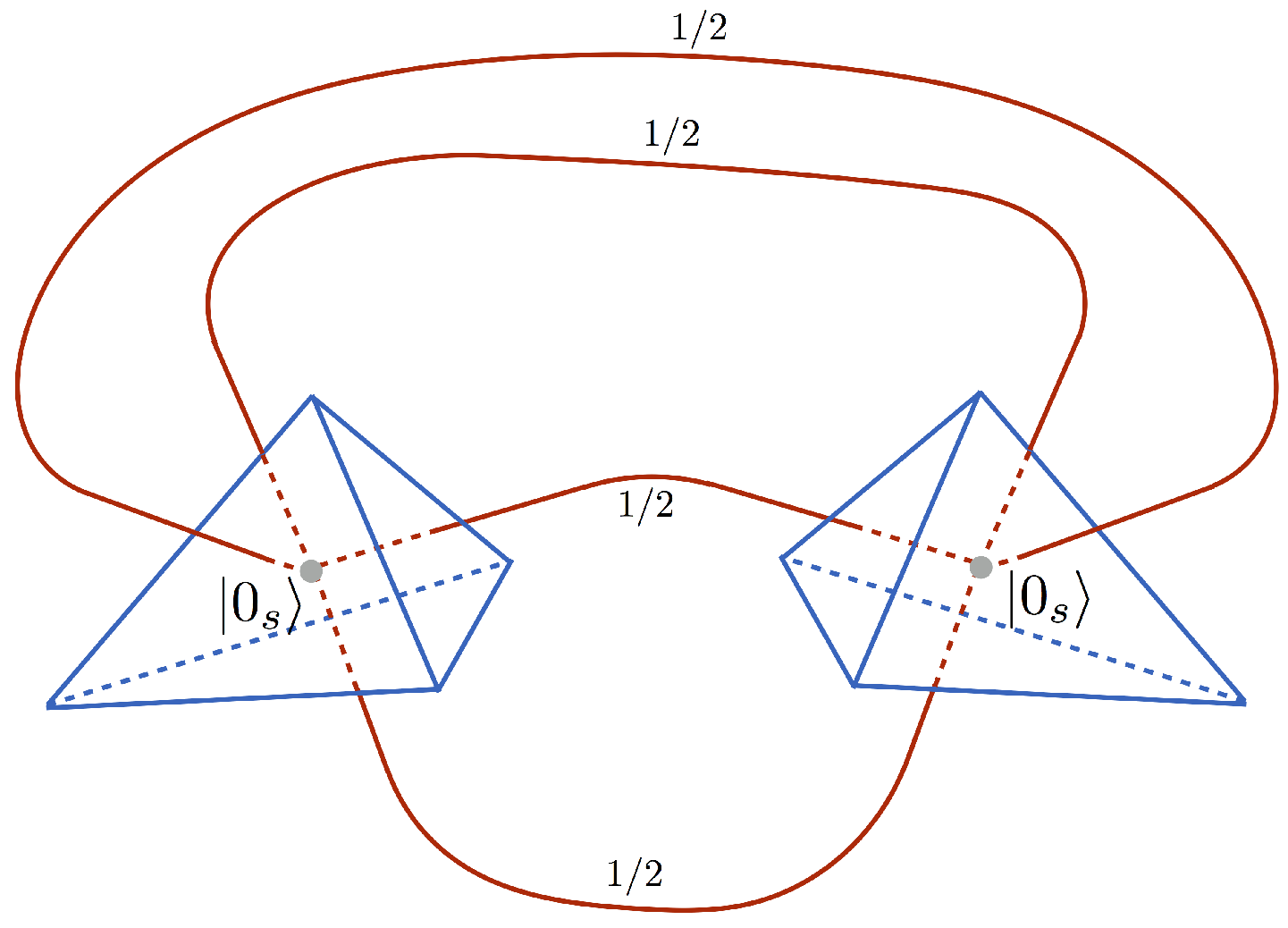
The second example concerns a bit more complex situation with two-node spin network presented in Figure 7.
Here, the representation state | W similarly to the previous example is associated with the Bell sates (22) entangling faces of the two tetrahedra one into another. The corresponding choice of the quantum circuit used to evaluate the boundary amplitude is presented in Figure 8.
The simulations were performed on both the IBM simulator and the QX simulator, with 1024 shots in each round. As in the previous example, the computational rounds have been repeated 10 times. The results obtained are collected in Table 3.
Performing averaging over the computational rounds the following values of | W | Ψ | 2 are obtained:
| W | Ψ | 2 = | a 0 | 2 = c c 0.063 ± 0.009 for QX simulator 0.060 ± 0.005 for IBM simulator .
The results are in agreement with the theoretically expected value | W | Ψ | 2 = | a 0 | 2 = 0 . 625 (obtained using Quirk [35]).

5. Evaluation of Vertex Amplitude

We are now ready to address the task of determining the vertex amplitude (19) associated with the boundary spin network state:
| Ψ = | 0 s | 0 s | 0 s | 0 s | 0 s .
The other possible choices of the spin network state will be discussed in our further work [34].
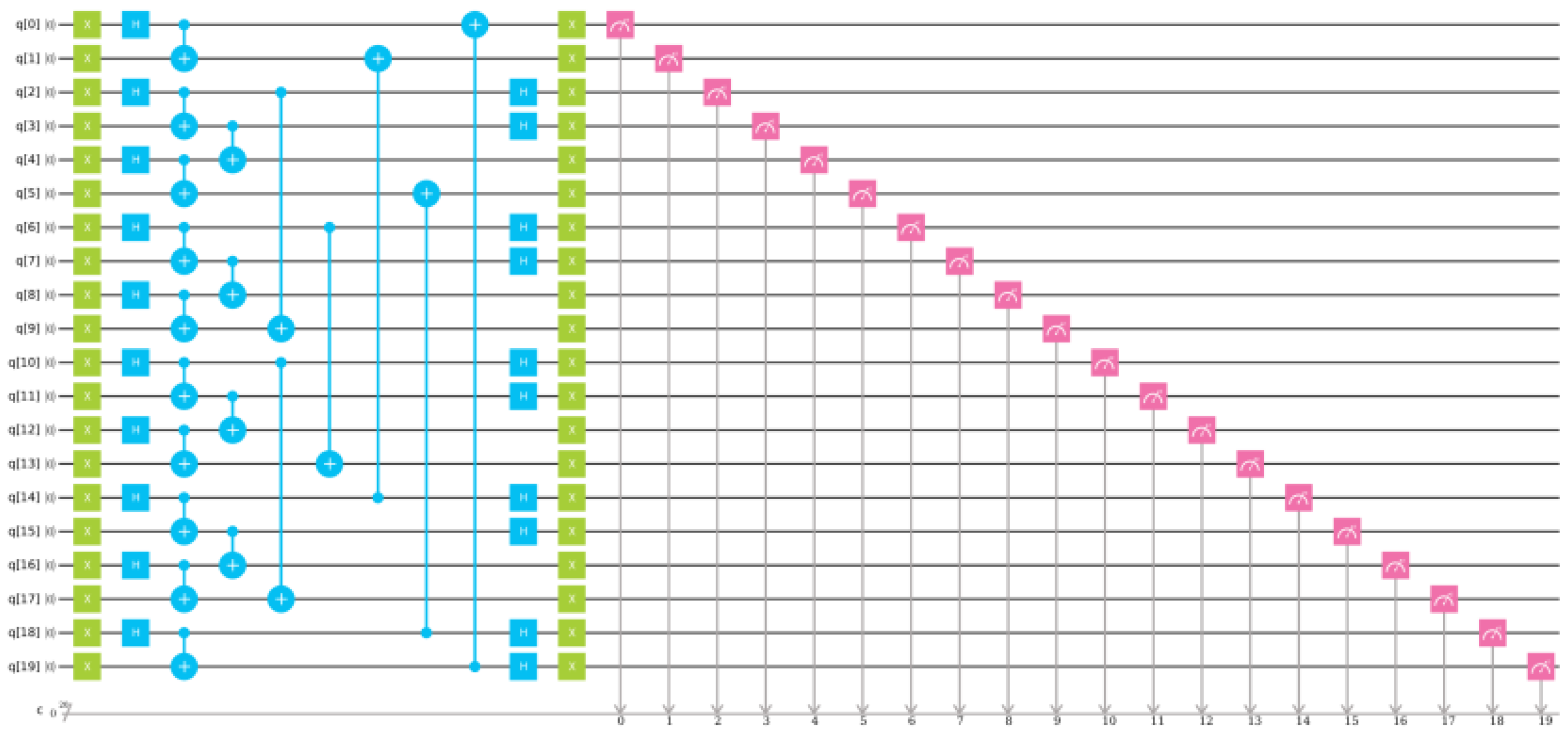
The | W is given by Equation (21), representing entanglement between faces of tetrahedra being connected by the links of the spin network. Due to anti-symmetricity of the Bell states (22) for the 10 links under consideration we have in general 2 10 = 1024 ways to order the states between the nodes of the spin network. Here, in order to not distinguish any of the nodes, the configuration in which every node is entangled with two other nodes by the state | E l = 1 2 | 01 | 10 and another two nodes by the state e i π | E l = 1 2 | 10 | 01 is considered. The resulting quantum circuit corresponding to the operator U ^ = U ^ W U ^ Ψ , together with the measurements necessary to find | a 0 | 2 = | W | Ψ | 2 is shown in Figure 9.
The quantum circuit employs 20-qubit quantum register with the initial state:
| 0 = n = 0 19 | 0 .
The algorithm introduced in Section 4 requires finding amplitude of the initial state (34) in the final state. One has to keep in mind that the Hilbert space of the 20-qubit system is spanned by over 1,000,000 basis states: 2 20 = 1048576 . Therefore, selecting amplitude of one of the basis states (i.e., | 0 ) is not an easy task.
The first attempt to determine the value of | W | Ψ | 2 = | A ( 0 s , 0 s , 0 s , 0 s , 0 s ) | 2 has been made by using the IBM simulator of quantum computer. Ten rounds of simulation, each of 1024 shots, have been performed. However, no single event with the | 0 state in the final state has been observed. Assuming that the probability is evenly distributed between the basis states, the probability 1 / 2 20 10 6 per basis states can be expected. With the 10,240 measurements made, this gives roughly 1 % chance to observe the state.
The second attempt to determine value of the vertex amplitude has been made with the use of the QX quantum computer simulator. Similarly to the simulations performed on the IBM simulator, 10 computational rounds, each of 1024 shots, have been performed. In this case, the events with | 0 have been observed and are collected in Table 4.
By averaging the results from Table 4, the following value of the modulus square of the vertex amplitude W | Ψ can be found:
| W | Ψ | 2 = | A ( 0 s , 0 s , 0 s , 0 s , 0 s ) | 2 = P 0 = 0.00147 ± 0.00095 .
The results obtained from the IBM and QX simulators are contradictory. However, the QX simulator result (35) is much closer to the theoretically expected value. Namely, the spin foam amplitude considered in this section can be determined using recoupling theory for S U ( 2 ) group. Following the discussion in Ref. [39] on can find that the amplitude (19) is given by the { 15 j } symbol. Employing definition of the symbol (see e.g., Equation (17) in Ref. [51]) for all the spin labels j a b = 1 / 2 and the intertwiners i a = 0 (which correspond to the | 0 s states), where a , b { 1 , 2 , 3 , 4 , 5 } , one can find that { 15 j } = 0.0625 . In consequence, | W | Ψ | 2 = | { 15 j } | 2 = 0.0625 2 = 0.00390625 . The difference between this prediction and the result of simulations (35) goes beyond the statistical error and, therefore, one can expect that systematic error was involved. Resolution of this issue requires further investigation, especially analysis of the sampling methods used in the quantum simulator. The same concerns the IBM quantum simulator, where discrepancy between the theoretically predicted value and the results of measurements is even more serious. Certainly, the employed publicly available platforms exhibit significant limitations. Nevertheless, they can be overcome by using more advanced simulators run on up-to-date computational clusters.
A more serious challenge is that the algorithm, in its current form, requires making measurements on all qubits involved in the circuit. In consequence, the number of measurements is growing exponentially with the number of quibits. Therefore, proposals of new algorithms, which will allow to reduce the number of measurements, are welcome (one of the possibilities is to use Quantum Phase Estimation Algorithm).
Taking the above into account, a comment on utility of the applied methodology is desirable. First of all, we already used the fact that the vertex amplitude discussed in this section can easily be evaluated without the need of quantum circuits. The vertex amplitude, associated with the pentagram spin network is given by the { 15 j } symbol. Recently, significant progress has been made in the development of numerical methods of evaluation of spin foam vertex amplitudes [52,53,54]. However, there are still some obstacles, e.g., oscillating nature of the spin foam amplitudes, which motivate search for alternative computational methods.
The aim of our study was to provide the proof of the concept of applicability of quantum circuits to determine quantities being of relevance in Loop Quantum Gravity and Spin Foam approaches. We have shown that indeed, despite the current hardware limitations (see Appendix A), interesting quantities can already be evaluated on simulators of quantum computers. As we demonstrated, 2 qubits per link of a spin network are needed for this purpose. Therefore, in case of the 5-node pentargam spin network (with 10 links) studied here, 20 qubit register was used. Utilizing the available commercial quantum simulators (e.g., 37 qubit QX multi-node simulator SurfSara [25]), amplitudes of spin networks with up to nine 4-valent nodes can potentially be computed.
Our plan is to perform such simulations in our further studies. Furthermore, our goal is to extend computational capabilities to 40 qubits using academic and commercial supercomputing resources. This will allow to simulate spin networks with 10 nodes. Worth mentioning is that while scaling the system size is straightforward for the method based on quantum circuits, application of the standard methods based on recoupling theory may turn out to be inefficient. This will become even more evident when advantageous quantum computers will become available (as expected) in the second half on the coming decade (see Appendix A), providing 100 and more fault tolerant qubits. Until that time, there is still a lot of potential for improving simulator-based computations and development of methods which will ultimately be applied on real quantum processors.
Furthermore, the introduced circuits for spin networks not only allow to study amplitudes but also other relevant quantities. In particular, analysis of quantum fluctuations and quantum entanglement between subsystems is possible to investigate. One of the open problems which is becoming possible to study by extending the methodology introduced here is the entanglement entropy between subsystems of spin networks and the issue of area law for entropy of entanglement.
In addition, while in the current setup we considered the spin labels j = 1 / 2 , the case of higher spins can potentially also be implemented. This would be relevant especially from the point of view of the semi-classical, large j limit. Taking into account the restricted computational resources, this can be done only by the cost of keeping the number of nodes small. Therefore, basically we have two domains which seem to be plausible to investigate in the coming decade. The first is the one with the small spin labels (e.g., j = 1 / 2 ) and the increasing number of nodes of a spin network—the direction towards the thermodynamic limit of a quantum system. The second is the case with small number of nodes (e.g., dipole spin network) and increasing values of the spin labels. This corresponds to a semi-classical limit of a microscopic chunk of space. On the other hand, the case where both the number of nodes and the spin labels are large is the most interesting one. Analysis of this limit will allow to investigate emergence of classical space(time) in loop quantum gravity and spin foam approaches. This will provide an opportunity to (at least partially) verify physical relevance of the candidates for theory of quantum gravity. However, sufficient quantum computational resources are not expected to be available earlier than in the fourth decade of this century (see Appendix A).
6. Summary

The purpose of this article was to explore the possibility of computing vertex amplitudes in the spin foam models of quantum gravity with the use of quantum algorithms. The notion of intertwiner qubit being crucial to implement the vertex amplitudes on quantum computers has been pedagogically introduced. It has been shown how one of the two basis states of the intertwiner qubit can be implemented with the use available IBM 5-qubit quantum computer. To the best of our knowledge it was the first time ever a quantum gravitational quantity has been simulated on superconducting quantum chip.
Thereafter, a quantum algorithm allowing to determine modulus square of spin foam vertex amplitude ( | W | Ψ | 2 ) has been introduced. Utility of the algorithm has been demonstrated on examples of single-node and two-node spin networks. For the two cases, probabilities of the associated boundary states have been determined with the use of IBM and QX quantum computer simulators. Finally, the algorithm has been applied to the case of pentagram spin network, representing boundary of the spin foam vertex. Value of the modulus square of the amplitude in a certain quantum state has been measured with the use of 20-qubit register of the IBM and QX quantum simulators. While the QX results were close to the analytically predicted value, the outcomes of the IBM simulator failed to reproduce theoretical predictions.
The presented results are the first step towards simulating spin foam models (associated with Loop Quantum Gravity and Group Field Theories) with the use of universal quantum computers. In particular, the vertex amplitudes can be applied as elementary building blocks in construction of more complex transition amplitudes. The aim of the developed direction is to achieve the possibility of studying collective behavior of the Planck scale systems composed of huge number of elementary constituents (“atoms of space/spacetime”). Exploration of the many-body Planck scale quantum systems [55] may allow to extract continuous and semi-classical limits from the dynamics of the “fundamental” degrees of freedom. This is crucial from the perspective of making contact between Planck scale physics and empirical sciences.
Worth stressing is that the results presented in this article are rather preliminary and only set up the stage for further, more detailed studies. In particular, the following points have to be addressed:
  • Introduction of a quantum circuit for the general intertwiner qubit | I (Equation (11)).
  • Determination of the phase of vertex amplitude with the use of quantum algorithms (e.g., Quantum Phase Estimation Algorithm [56]).
  • Investigation of different types of the state | W .
  • Analysis of spin networks with up to 10 nodes on quantum computers simulators.
  • A possibility of solving quantum constraints with the use of quantum circuits.
  • Application to Spinfoam cosmology [48,49].
  • Investigation of the architectures of forthcoming quantum processors (with the N > 100 number of qubits) in terms of application to spin foam transition amplitudes.
Some of the tasks will be subject of a sequel to this article [34].

Funding

This research was funded by the Sonata Bis Grant DEC-2017/26/E/ST2/00763 of the National Science Centre Poland and the Mobilność Plus Grant 1641/MON/V/2017/0 of the Polish Ministry of Science and Higher Education.

Conflicts of Interest

The author declare no conflict of interest.

Appendix A. Quantum Computing Technologies

The domain of quantum computing is currently experiencing an unprecedented speedup. The recent progress is mainly due to advances in development of the superconducting qubits [23]. In particular, utilizing the superconducting circuits, the IBM company has developed 5 and 20 qubit (noisy) quantum computers, which are accessible in cloud [22]. Furthermore, a prototype of 50 qubit quantum computer by this company has been built and is currently in the phase of tests. The company has recently also unveiled its first commercial 20-qubit quantum computer IBM Q System One. This is intended to be the first ever commercial universal quantum computer, and the second commercially available quantum computer after the adiabatic quantum computer (quantum annealer [57]) provided by D-Wave Systems [58]. The latests D-Wave 2000Q annealer uses a quantum chip with 2048 superconducting qubits, connected in the form of the so-called chimera graph. Another important player in the quantum race is Intel, which recently developed its 49-qubit superconducting quantum chip named Tangle Lake [59]. However, outside of the superconducting qubits, the company in collaboration with QuTech [60] advanced centre for Quantum Computing and Quantum Internet is also developing an approach to quantum computing based on electron’s spin based qubits, stored in quantum dots. Further advances in the area of superconducting quantum circuits come from Google [61] and Rigetti Computing [62]. The first company has recently announced their 72-qubit quantum chip, while the second one is currently developing its 128-qubit universal quantum chip. On the other hand, the world’s leading software company—Microsoft has focused its approach to quantum computing on topological qubits through Majorana fermions [63]. The alternative to superconducting qubits is also developed by IonQ Inc. startup, which is developing a trapped ion quantum computer based on ytterbium atoms [64]. The most recent quantum computer by this company allows to operate on 79 qubits, which is the current world record. The above are only the most sound examples of the advancement which has been made in the recent years in the area of hardware dedicated to quantum computing. There are still many challenges to be addressed, including reduction of the gate errors and increase of fidelity of the quantum states. However, even in pessimistic scenarios, the current momentum of the quantum computing technologies will undoubtedly lead to emergence of reliable and advantageous quantum machines (which cannot be emulated on classical supercomputers) in the coming decade. There are no fundamental physical reasons identified, which could stop the progress. However, the rate of the progress will depend on whether commercial applications of quantum computing technologies will emerge in the coming five years, stimulating further funding of research and development. See e.g., Ref. [65] for more detailed discussion of this issue.
Major players in the field, with large financial resources, such as IBM or governments may sustain the progress independently on short-term returns (which is not the case for start-ups). This may allow for a stable long term progress. In particular, IBM has recently announced a possibility of doubling a measure called Quantum Volume [66] every year [67]. The Quantum Volume V Q is basically a maximal size of a certain random circuit, with equal width and depth, which can be successfully implemented on a given quantum computer. The current (2019) IBM’s value of V Q is 16 and corresponds to the IBM Q System One quantum computer mentioned above. This means that any quantum algorithm employing 4 qubits and four layers (time steps) of quantum circuit can be successfully implemented on the computer. If the trend will follow the hypothesized geometric trajectory (a sort of a new Moore’s law [68] for integrated circuits), then one could expect the quantum volume V Q to be of the order of 10 3 in 2025 and 10 5 in 2030. This means that in 2025, algorithms employing roughly log 2 10 3 10 qubits and the same number of time steps will be possible to execute. This number will increase to approximately 16 qubits until the end of the coming decade. While this may not sound very optimistic, the prediction is very conservative and does not rule out that much bigger (non-random) circuits (especially well-fitted to the hardware) will be possible to execute at the same time.

Appendix B. Basics of Quantum Computing

The aim of the appendix is to provide a basic introduction of the concepts in quantum computing used in this article. This appendix will allow quantum gravity researchers who are not familiar with quantum computing, to grasp the relevant concepts.
The quantum computing is basically processing of quantum information. While the elementary portion of classical information is a bit { 0 , 1 } , its quantum counterpart is what we call a qubit. A single qubit is a state | Ψ in two-dimensional Hilbert space, which we denote as H = span { | 0 , | 1 } . The space is spanned by two orthonormal basis states | 0 and | 1 , so that 1 | 0 = 0 and 0 | 0 = 1 = 1 | 1 . A general qubit is a superposition of the two basis states:
| Ψ = α | 0 + β | 1 ,
where, α , β C (complex numbers), and the normalization condition Ψ | Ψ = 1 implies that | α | 2 + | β | 2 = 1 .
There are different unitary quantum operations which may be performed on the quantum state | Ψ . The elementary quantum operations are called gates, in analogy to electric circuits implementing Boolean logic. For instance, the so-called bit-flip operator X ^ which transforms | 0 into | 1 and | 1 into | 0 ( X ^ | 0 = | 1 and X ^ | 1 = | 0 ) can be introduced. The X ^ operator introduces the NOT operation on a single qubit, and has representation in the form of the Pauli x matrix. Similarly, one can introduce Y ^ and Z ^ operators corresponding to the other two Pauli matrices. The computational basis { | 0 , | 1 } is usually introduced such that the basis states are eigenvectors of the Z ^ operator: Z ^ | 0 = | 0 and Z ^ | 1 = | 1 .
Another important operator (which does not have its classical counterpart) is the Hadamard operator H ^ which is defined by the following action on the qubit basis states:
H ^ | 0 = 1 2 | 0 + | 1 and H ^ | 1 = 1 2 | 0 | 1 .
The above are examples of operators acting on a single qubit. However, quantum information processing usually concerns a multiple qubit system called quantum register. The quantum state of the register of N qubits belongs to a tensor product of N copies of single qubit Hilbert spaces: i = 1 N H i . The dimension of the product Hilbert space is dim i = 1 N H i = 2 N . This exponential dependence of the dimensionality on N is the main obstacle behind simulating quantum systems on classical computers.
A quantum algorithm is a unitary operator U ^ acting on the initial state of the quantum registes | 0 : = i = 1 N | 0 i = 1 N H i , together with a sequence of measurements. The outcome of the quantum algorithm is obtained by performing measurements on the final sate: U ^ | 0 . Because of the probabilistic nature of quantum mechanics, the procedure has to be performed repeatedly in order to reconstruct the final state. In general, full reconstruction of the final state U ^ | 0 requires the so-called quantum tomography to be applied. In the procedure, states of the qubits are measured in different bases (not only in the computational basis). The quantum state tomography, which reconstructs the density matrix ρ ^ = U ^ | 0 0 | U ^ , is however not always required. In most of the considered quantum algorithms, only probabilities (not complex amplitudes) of the basis states are necessary to measure, which is much simpler and faster than the quantum state tomography.
As already mentioned, the unitary operator U ^ can be decomposed into elementary operations called quantum gates. The already introduced X ^ and H ^ operators are examples of single-qubit gates. However, the gates may also act on two or more qubits. An example of 2-qubit gate relevant for the purpose of this article is the so-called controlled-NOT (CNOT) gate, which we denote as C ^ . The operator is acting on 2-qubit state | a b | a | b , where | a and | b are single quibit states. Action of the CNOT operator on the basis states can be expressed as follows: C ^ ( | a | b ) = | a | a b , where a , b { 0 , 1 } . The ⊕ is the XOR (exclusive or) logical operation (equivalent to addition modulo 2), defined as 0 b = b , and 1 b = ¬ b , where by ¬ b we denote negation (NOT) of b. This explains why the gate is called the controlled-NOT (CNOT). The first qubit ( | a ) is a control qubit, while the second ( | b ) is a target qubit. The first qubits acts as a switch, which turns on negation of the second quibit if a = 1 and remain the second qubit unchanged if a = 0 .
The diagrammatic representation of the of the unitary operator U ^ composed of elementary quantum gates is called a quantum circuit, examples of which can be found through this article. Each computational qubit is associated with a horizontal line, which arranges the order at which the operations are performed (direction of time). The operations are executed from the left to the right. Then, the symbols representing gates can be place on either a single-qubit line (e.g., X,Y,Z,H gates) or by joining two or more lines (e.g., CNOT, Toffoli gates).
One of the advantages of quantum algorithms is the possibility of implementing the so-called quantum parallelism, which allows to reduce computational complexity of certain problems. The most known example is the Shor algorithm [69] which allows to reduce classical NP complexity of the factorization problem into the BQP complexity class (see e.g., Ref. [70] for definitions of complexity classes). Another seminal example is the Grover algorithm [71] which, statistically, reduces the number of steps needed to find an element in the random database containing N elements from classical N / 2 to O ( N ) . Even if we do not make use of quantum parallelism and the resulting reduction of computational complexity in this paper, the methods may also find application in the context of simulations of spin networks. This especially concerns the Quantum Phase Estimation Algorithm [56] which may possibly be applied to effectively measure phases of the spin foam amplitudes.

References

  1. Ambjorn, J.; Goerlich, A.; Jurkiewicz, J.; Loll, R. Nonperturbative Quantum Gravity. Phys. Rept. 2012, 519, 127–210. [Google Scholar] [CrossRef]
  2. Ambjorn, J.; Jordan, S.; Jurkiewicz, J.; Loll, R. A Second-order phase transition in CDT. Phys. Rev. Lett. 2011, 107, 211303. [Google Scholar] [CrossRef] [PubMed]
  3. Bilke, S.; Burda, Z.; Jurkiewicz, J. Simplicial quantum gravity on a computer. Comput. Phys. Commun. 1995, 85, 278–292. [Google Scholar] [CrossRef] [Green Version]
  4. Di Francesco, P.; Ginsparg, P.H.; Zinn-Justin, J. 2-D Gravity and random matrices. Phys. Rept. 1995, 254, 1–133. [Google Scholar] [CrossRef]
  5. ’t Hooft, G. A Planar Diagram Theory for Strong Interactions. Nucl. Phys. B 1974, 72, 461–473. [Google Scholar] [CrossRef]
  6. Ashtekar, A.; Lewandowski, J. Background independent quantum gravity: A Status report. Class. Quantum Gravity 2004, 21, R53. [Google Scholar] [CrossRef]
  7. Rovelli, C.; Vidotto, F. Covariant Loop Quantum Gravity: An Elementary Introduction to Quantum Gravity and Spinfoam Theory; Cambridge Monographs on Mathematical Physics; Cambridge University Press: Cambridge, UK, 2014. [Google Scholar]
  8. Rovelli, C.; Smolin, L. Spin networks and quantum gravity. Phys. Rev. D 1995, 52, 5743–5759. [Google Scholar] [CrossRef] [PubMed] [Green Version]
  9. Baez, J.C. Spin foam models. Class. Quantum Gravity 1998, 15, 1827–1858. [Google Scholar] [CrossRef] [Green Version]
  10. Perez, A. The Spin Foam Approach to Quantum Gravity. Living Rev. Relat. 2013, 16, 3. [Google Scholar] [CrossRef] [PubMed]
  11. Engle, J.; Pereira, R.; Rovelli, C. The Loop-quantum-gravity vertex-amplitude. Phys. Rev. Lett. 2007, 99, 161301. [Google Scholar] [CrossRef] [PubMed]
  12. Bianchi, E.; Hellmann, F. The Construction of Spin Foam Vertex Amplitudes. SIGMA 2013, 9, 008. [Google Scholar] [CrossRef]
  13. Oriti, D. The Group field theory approach to quantum gravity. In Approaches to Quantum Gravity; Oriti, D., Ed.; Cambridge University Press: Cambridge, UK, 2009; pp. 310–331. [Google Scholar]
  14. Freidel, L. Group field theory: An Overview. Int. J. Theor. Phys. 2005, 44, 1769–1783. [Google Scholar] [CrossRef]
  15. Krajewski, T. Group field theories. Presented at the 3rd Quantum Gravity and Quantum Geometry School (QGQGS 2011), Zakopane, Poland, 28 February–13 March 2011. [Google Scholar]
  16. Ooguri, H. Topological lattice models in four-dimensions. Mod. Phys. Lett. A 1992, 7, 2799–2810. [Google Scholar] [CrossRef]
  17. Gielen, S.; Oriti, D.; Sindoni, L. Cosmology from Group Field Theory Formalism for Quantum Gravity. Phys. Rev. Lett. 2013, 111, 031301. [Google Scholar] [CrossRef] [PubMed]
  18. Benedetti, D.; Geloun, J.B.; Oriti, D. Functional Renormalisation Group Approach for Tensorial Group Field Theory: A Rank-3 Model. J. High Energy Phys. 2015, 2015, 084. [Google Scholar] [CrossRef]
  19. Li, K.; Li, Y.; Han, M.; Lu, S.; Zhou, J.; Ruan, D.; Long, G.; Wan, Y.; Lu, D.; Zeng, B.; et al. Quantum Spacetime on a Quantum Simulator. arXiv 2017, arXiv:1712.08711. [Google Scholar]
  20. Feller, A.; Livine, E.R. Ising Spin Network States for Loop Quantum Gravity: A Toy Model for Phase Transitions. Class. Quantum Gravity 2016, 33, 065005. [Google Scholar] [CrossRef]
  21. Mielczarek, J. Spin networks on adiabatic quantum computer. arXiv 2018, arXiv:1801.06017. [Google Scholar]
  22. Available online: https://www.research.ibm.com/ibm-q/ (accessed on 25 July 2019).
  23. You, J.Q.; Nori, F. Superconducting Circuits and Quantum Information. Phys. Today 2005, 58, 42–47. [Google Scholar] [CrossRef] [Green Version]
  24. Available online: http://quantum-studio.net/ (accessed on 25 July 2019).
  25. Available online: https://www.quantum-inspire.com/ (accessed on 25 July 2019).
  26. Feynman, R.P. Simulating physics with computers. Int. J. Theor. Phys. 1982, 21, 467–488. [Google Scholar] [CrossRef]
  27. Mielczarek, J. Quantum Gravity on a Quantum Chip. arXiv 2018, arXiv:1803.10592. [Google Scholar]
  28. Albash, T.; Lidar, D.A. Adiabatic Quantum Computing. Rev. Mod. Phys. 2018, 90, 015002. [Google Scholar] [CrossRef]
  29. Deutsch, D.; Barenco, A.; Ekert, A. Universality in quantum computation. Proc. R. Soc. Lond. A 1995, 449, 669–677. [Google Scholar] [CrossRef] [Green Version]
  30. Ekert, A.; Hayden, P.; Inamori, H. Basic concepts in quantum computation. arXiv 2011, arXiv:quant-ph/0011013. [Google Scholar]
  31. Chen, Z.Y.; Zhou, Q.; Xue, C.; Yang, X.; Guo, G.C.; Guo, G.P. 64-Qubit Quantum Circuit Simulation. Sci. Bull. 2018, 63, 964–971. [Google Scholar] [CrossRef]
  32. Biamonte, J.D.; Morales, M.E.S.; Koh, D.E. Quantum Supremacy Lower Bounds by Entanglement Scaling. arXiv 2018, arXiv:1808.00460. [Google Scholar]
  33. Long, G.L.; Sun, Y. Efficient Scheme for Initializing a Quantum Register with an Arbitrary Superposed State. Phys. Rev. A 2001, 64, 014303. [Google Scholar] [CrossRef]
  34. Mielczarek, J. Quantum circuits for a qubit of space. 2019; In preparation. [Google Scholar]
  35. Available online: https://algassert.com/quirk (accessed on 25 July 2019).
  36. Available online: https://sites.google.com/view/quantum-kit/home (accessed on 25 July 2019).
  37. Nielsen, M.A.; Chuang, I.L. Quantum Computation and Quantum Information; Cambridge University Press: Cambridge, UK, 2000. [Google Scholar]
  38. Oeckl, R. A ‘General boundary’ formulation for quantum mechanics and quantum gravity. Phys. Lett. B 2003, 575, 318–324. [Google Scholar] [CrossRef]
  39. Baytas, B.; Bianchi, E.; Yokomizo, N. Gluing polyhedra with entanglement in loop quantum gravity. Phys. Rev. D 2018, 98, 026001. [Google Scholar] [CrossRef] [Green Version]
  40. Maldacena, J.M. The Large N limit of superconformal field theories and supergravity. Int. J. Theor. Phys. 1999, 38, 1113–1133. [Google Scholar] [CrossRef]
  41. Susskind, L. Dear Qubitzers, GR=QM. arXiv 2017, arXiv:1708.03040. [Google Scholar]
  42. Swingle, B. Entanglement Renormalization and Holography. Phys. Rev. D 2012, 86, 065007. [Google Scholar] [CrossRef]
  43. Ryu, S.; Takayanagi, T. Holographic derivation of entanglement entropy from AdS/CFT. Phys. Rev. Lett. 2006, 96, 181602. [Google Scholar] [CrossRef] [PubMed]
  44. Rangamani, M.; Takayanagi, T. Holographic Entanglement Entropy; Lecture Notes in Physics; Springer: Cham, Switzerland, 2017; Volume 931, p. 1. [Google Scholar]
  45. Han, M.; Hung, L.Y. Loop Quantum Gravity, Exact Holographic Mapping, and Holographic Entanglement Entropy. Phys. Rev. D 2017, 95, 024011. [Google Scholar] [CrossRef]
  46. Biamonte, J.; Bergholm, V. Tensor Networks in a Nutshell. arXiv 2017, arXiv:1708.00006. [Google Scholar]
  47. Bojowald, M. Loop quantum cosmology. Living Rev. Relat. 2008, 11, 4. [Google Scholar] [CrossRef] [PubMed]
  48. Bianchi, E.; Rovelli, C.; Vidotto, F. Towards Spinfoam Cosmology. Phys. Rev. D 2010, 82, 084035. [Google Scholar] [CrossRef]
  49. Vidotto, F. Spinfoam Cosmology: Quantum cosmology from the full theory. J. Phys. Conf. Ser. 2011, 314, 012049. [Google Scholar] [CrossRef]
  50. Czech, B.; Lamprou, L.; Susskind, L. Entanglement Holonomies. arXiv 2018, arXiv:1807.04276. [Google Scholar]
  51. Donà, P.; Fanizza, M.; Sarno, G.; Speziale, S. SU(2) graph invariants, Regge actions and polytopes. Class. Quantum Gravity 2018, 35, 045011. [Google Scholar] [CrossRef] [Green Version]
  52. Sarno, G.; Speziale, S.; Stagno, G.V. 2-vertex Lorentzian Spin Foam Amplitudes for Dipole Transitions. Gen. Relat. Gravit. 2018, 50, 43. [Google Scholar] [CrossRef]
  53. Dona, P.; Sarno, G. Numerical methods for EPRL spin foam transition amplitudes and Lorentzian recoupling theory. Gen. Relat. Gravit. 2018, 50, 127. [Google Scholar] [CrossRef] [Green Version]
  54. Dona, P.; Fanizza, M.; Sarno, G.; Speziale, S. Numerical study of the Lorentzian EPRL spin foam amplitude. arXiv 2019, arXiv:1903.12624. [Google Scholar]
  55. Oriti, D. Spacetime as a quantum many-body system. arXiv 2017, arXiv:1710.02807. [Google Scholar]
  56. Cleve, R.; Ekert, A.; Macchiavello, C.; Mosca, M. Quantum algorithms revisited. Proc. R. Soc. Lond. A 1998, 454, 339–354. [Google Scholar] [CrossRef] [Green Version]
  57. Kadowaki, T.; Nishimori, H. Quantum annealing in the transverse Ising model. Phys. Rev. E 1998, 58, 5355. [Google Scholar] [CrossRef]
  58. Available online: https://www.dwavesys.com/home (accessed on 25 July 2019).
  59. Available online: https://newsroom.intel.com/press-kits/quantum-computing/hashkeytag|quantum-computing (accessed on 25 July 2019).
  60. Available online: https://qutech.nl/ (accessed on 25 July 2019).
  61. Available online: https://ai.google/research/teams/applied-science/quantum-ai/ (accessed on 25 July 2019).
  62. Available online: https://www.rigetti.com/ (accessed on 25 July 2019).
  63. Available online: https://www.microsoft.com/en-us/quantum/ (accessed on 25 July 2019).
  64. Available online: https://ionq.co/ (accessed on 25 July 2019).
  65. Grumbling, E.E.; Horowitz, M. Quantum Computing—Progress and Prospects; The National Academies Press: Washington, DC, USA, 2019. [Google Scholar]
  66. Cross, A.W.; Bishop, L.S.; Sheldon, S.; Nation, P.D.; Gambetta, J.M. Validating quantum computers using randomized model circuits. arXiv 2018, arXiv:1811.12926. [Google Scholar]
  67. Available online: https://www.ibm.com/blogs/research/2019/03/power-quantum-device/ (accessed on 25 July 2019).
  68. Moore, G.E. Cramming more components onto integrated circuits. Electronics 1965, 38, 114–117. [Google Scholar] [CrossRef]
  69. Shor, P.W. Algorithms for quantum computation: Discrete logarithms and factoring. In Proceedings of the 35th Annual Symposium on Foundations of Computer Science, Santa Fe, NM, USA, 20–22 November1994; pp. 124–134. [Google Scholar]
  70. Available online: https://complexityzoo.uwaterloo.ca/Complexityunderlinetag_Zoo (accessed on 25 July 2019).
  71. Grover, L.K. A Fast quantum mechanical algorithm for database search. In Proceedings of the 28th Annual ACM Symposium on the Theory of Computing, Philadelphia, PA, USA, 22–24 May 1996. [Google Scholar]
1.
In general, quantum variables associated with higher dimensional Hilbert spaces may be considered.
2.
In order to prove it let us consider an asymmetric 1D random walk with probabilities p = 1 16 (one of the basis states) and q = 1 p = 15 16 (rest of the 15 basis sates), for which s n = 1 16 15 16 1 n 1 4 n .
3.
Performing an inverse mapping h ^ x ( π / 2 ) we can map the state i | 1 back to h ^ x ( π / 2 ) i | 1 = i X ^ i | 1 = | 0 .
4.
This statement is made under assumption that no ancilla qubits are required.
Figure 1. Pictorial representation of a simple spin foam associated with 2+1 D gravity. The plot has been inspired by Figure 4.2 in Ref. [7].
Universe 05 00179 g001
Figure 2. A single 4-valent node together with the entering links with spin labels j = 1 / 2 . The intertwiner qubit | I is a degree of freedom defined at the node. The node is dual to the tetrahedron (3-symplex) as represented in the picture.
Universe 05 00179 g002
Figure 3. Quantum circuit used to generate | 0 s state from the initial state | 0000 . The (green) boxes with letter X represent the bit-flip gates, the (blue) boxes with letter H represents the Hadamard gates, while the next operations from the left are the CNOT 2-qubit gates. Finally, the (pink) boxes on the right represent measurements performed at every one of the four involved qubits.
Universe 05 00179 g003
Figure 4. Pentagram spin network corresponding to boundary of a single vertex of spin foam. The boundary geometry has topology of three-sphere.
Universe 05 00179 g004
Figure 5. A single-node spin network associated with identification of the pairs of face of a tetrahedron.
Universe 05 00179 g005
Figure 6. Quantum circuit used to evaluate | W | Ψ | 2 the boundary transition amplitude of the spin network presented in Figure 5.
Universe 05 00179 g006
Figure 7. A two-node spin network associated with two tetrahedra.
Universe 05 00179 g007
Figure 8. Quantum circuit used to evaluate | W | Ψ | 2 the boundary transition amplitude of the spin network presented in Figure 7. The qubits { 0 , 1 , 2 , 3 } belong to the one node while the qubits { 4 , 5 , 6 , 7 } belong to the another. The links are between the pairs of qubits: { 0 , 4 } , { 1 , 5 } , { 2 , 6 } and { 3 , 7 } .
Universe 05 00179 g008
Figure 9. Quantum circuit used to determine | A ( 0 s , 0 s , 0 s , 0 s , 0 s ) | 2 . Nodes of the spin network correspond to the following sets of qubits: { 0 , 1 , 2 , 3 } , { 4 , 5 , 6 , 7 } , { 8 , 9 , 10 , 11 } , { 12 , 13 , 14 , 15 } , { 16 , 17 , 18 , 19 } . The links are between the pairs of qubits: { 0 , 19 } , { 1 , 14 } , { 2 , 9 } , { 3 , 4 } , { 5 , 18 } , { 6 , 13 } , { 7 , 8 } , { 10 , 17 } , { 11 , 12 } and { 15 , 16 } .
Universe 05 00179 g009
Table 1. Results of measurements of P ( i ) = | a i | 2 for the quantum circuit presented in Figure 3.
No.ProbabilityTheoryIBM SimulatorIBM Q ibmqx4QX Simulator
1 | a 0000 | 2 000.0140
2 | a 0001 | 2 000.0580
3 | a 0010 | 2 000.0500
4 | a 0011 | 2 000.0040
5 | a 0100 | 2 000.0230
6 | a 0101 | 2 0.250.2640.1090.252
7 | a 0110 | 2 0.250.2320.0910.241
8 | a 0111 | 2 000.0090
9 | a 1000 | 2 000.0340
10 | a 1001 | 2 0.250.2480.1590.230
11 | a 1010 | 2 0.250.2560.1580.276
12 | a 1011 | 2 000.0120
13 | a 1100 | 2 000.0340
14 | a 1101 | 2 000.1320
15 | a 1110 | 2 000.1100
16 | a 1111 | 2 000.0030
Table 2. Results of measurements of P ( 0 ) = | a 0 | 2 for the quantum circuit presented in Figure 6, using both the IBM simulator and the QX simulator. Each measurement corresponds to the number of shots equal to 1024.
No. P 0 (QX)Hits of | 0 (QX) P 0 (IBM)Hits of | 0 (IBM)
10.2558593752620.263671875270
20.2480468752540.2529296875259
30.2675781252740.2578125264
40.25683593752630.27734375284
50.25683593752630.232421875238
60.252560.263671875270
70.25781252640.25256
80.238281252440.244140625250
90.2402343752460.2607421875267
100.252560.2763671875283
Table 3. Results of measurements of P ( 0 ) = | a 0 | 2 for the quantum circuit presented in Figure 8 using both the IBM simulator and the QX simulator. Each measurement corresponds to the number of shots equal 1024.
No. P 0 (QX)Hits of | 0 (QX) P 0 (IBM)Hits of | 0 (IBM)
10.0595703125610.055664062557
20.0595703125610.0664062568
30.06640625680.06054687562
40.0615234375630.06445312566
50.080078125820.063476562565
60.0498046875510.059570312561
70.052734375540.061523437563
80.072265625740.053710937555
90.0673828125690.05273437554
100.0634765625650.065429687567
Table 4. Results of measurements of P ( 0 ) = | a 0 | 2 for the quantum circuit presented in Figure 9 using the QX simulator. Each measurement corresponds to the number of shots equal to 1024.
No. P 0 Hits of | 0
10.00097656251
20.00292968753
300
40.00097656251
50.0019531252
60.00097656251
70.0019531252
80.00097656251
90.00292968753
100.00097656251