Abstract
The Compact Muon Solenoid (CMS) detector is one of the two multipurpose experiments at the Large Hadron Collider (LHC). It has successfully collected data during Run 1 (2010–2013) and achieved important physics results, like the discovery of the Higgs boson announced in 2012. Willing to unravel further open questions not yet explained by the standard model, intense activities have been performed to further improve the detector and the trigger before the LHC restart in 2016 (Run 2), in parallel with the upgrade of the LHC. The achieved global performance of the CMS experiment and of several subdetectors will be presented.
1. The CMS Detector
The Compact Muon Solenoid (CMS) [1] experiment is a general-purpose experiment built at the Large Hadron Collider (LHC). The CMS detectors use several technologies for particle detection and reconstruction. From the innermost part towards the outside, the silicon tracker reconstructs the trajectories of charged particles, the Electromagnetic Calorimeter (ECAL) and Hadron Calorimeter (HCAL) measure the energy of electromagnetic particles and hadrons, while the muon system occupies the most external part of the CMS detector outside the superconducting solenoid. The latter is a redundant system based on three different gaseous detector technologies, namely Drift Tubes (DTs), Cathode Strip Chambers (CSCs), and Resistive Plate Chambers (RPCs).
2. Overview of CMS during LHC Run 2
The LHC Run 2 started in 2015 and recently finished in November 2018, for a total delivered luminosity of ∼163 fb (∼68 fb in 2018), during which the CMS detector ran in general stably and with a very high efficiency and a negligible dead time also at the highest luminosities. The LHC touched the peak luminosity value of Hz/nb in 2018, about twice the operational value.
Several upgrades and changes were performed in 2017–2018. In 2017, a new pixel detector was installed, the readout of the Hadron Forward (HF) calorimeter and of a 20 sector of HCAL were upgraded, and five chambers of new Gas Electron Multiplier (GEM) detectors covering 50 were installed in the negative end cap of the muon system. In 2018, all DC-DC converters of the pixel subdetector were replaced, the silicon strip tracker started operating at a lower temperature, ECAL was equipped with new DAQ links, Hybrid PhotoDetectors (HPDs) of the hadron end cap calorimeter were replaced with Silicon PhotoMultipliers (SiPMs), and DTs were equipped with micro Trigger Control and Acquisition (TCA) ROS.
3. The Inner Tracker
During Run 1, some dynamic inefficiencies were observed in the pixel subdetector, of the order of about 5% at an event pile-up of 40 in the first barrel layer, due to the limited size of the readout bandwidth. A new pixel detector was installed in March 2017 [2], equipped with one additional barrel layer and one additional forward disk. In the new pixel detector, the innermost layer is closer to the interaction point and the outermost one is further away from it (Figure 1). It also uses new Readout Chips (ROCs) with reduced data loss at higher collision rates with respect to Phase 1 (160 Mbit/s), and the bandwidth of the readout electronics was increased approximately by a factor of eight (320 Mbit/s). In addition, DC-DC power converters were installed to allow reusing the existing fibers and cables. Hence, the upgraded pixel detector has a higher rate capability and number of channels, providing increased tracking efficiency, reduced fake rate, and improved impact parameter resolution.

Figure 1.
Schematic drawing of the upgrade of the pixel detector. The lower half shows the old pixel detector, and the upper half represents the newly-installed detector.
In particular, Figure 2 shows the comparison of the dynamic efficiency observed during 2016 with the previous pixel detector and the dynamic efficiency observed in 2017 with the new one. A clear improvement is visible.
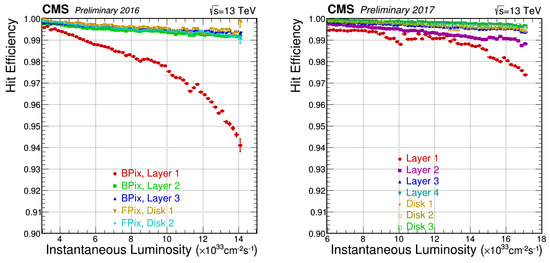
Figure 2.
Hit efficiency of the pixel detector as a function of the instantaneous luminosity during Run 1 measured with 2016 data (left) and during Run 2 measured with 2017 data (right) [3].
In late 2017, a failure of about 5% of the DC-DC power converters was observed, resulting in a marginal impact on the 2017 data quality. All DC-DC modules were replaced in the end-of-year technical stop of 2017–2018. After this intervention, the issue of the DC-DC power converters did not repeat in 2018, with the pixel detector running with high efficiency and a high fraction of active channels.
The silicon strips reconstruct tracks with two-dimensional resolution, with 200 m of p-in-n-type silicon strip sensors. During Run 1 (2010–2013), they were operated at +4 C using a fluorocarbon cooling system, while since 2017 (Run 2), they have been operated at a lower temperature (−20 C) to mitigate long-term damages. Since then, they have been operating in a very good status with a good signal-to-noise ratio, an example of which is shown in Figure 3.
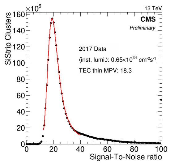
Figure 3.
Distribution of the signal-to-noise ratio measured on TEC with 2017 data [4].
4. The Electromagnetic Calorimeter
The CMS electromagnetic calorimeter [5] is a very compact homogeneous calorimeter composed of lead tungstate (PbWO) crystals with high granularity, a fast scintillation response (∼80% of the light is emitted within 25 ns), and excellent time resolution. The channels’ response changes with radiation, featuring both short-term variations (typically within an LHC fill) dependent on the instantaneous luminosity and log-term drifts depending on the integrated luminosity (Figure 4) [6]. Hence, the response is monitored with laser light every 40 min in order to apply corrections both in the trigger and offline. The decay is used as prompt feedback to monitor the effectiveness of the Laser Monitoring (LM) calibration and to inter-calibrate the energy of ECAL crystals. Figure 5 shows the reconstruction of the invariant mass of after the LM calibration made with 2017 data.
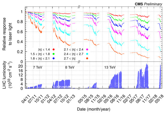
Figure 4.
The Electromagnetic Calorimeter (ECAL) relative response to the laser light and LHC instantaneous luminosity as a function of time [7].
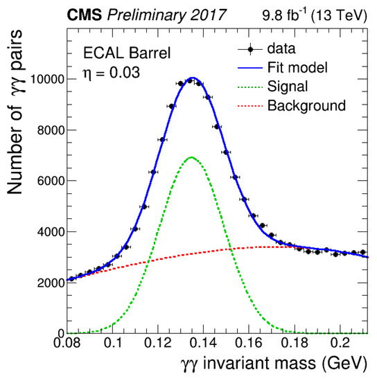
Figure 5.
Reconstruction of the invariant mass with ECAL after the calibration with laser monitoring performed with 2017 data [7].
5. The Hadron Calorimeter
The central hadron calorimeter [8], divided into the Hadron calorimeter Barrel (HB) and End cap (HE), is a sampling calorimeter using a brass absorber and plastic scintillator tiles. In addition, the HB calorimeter is complemented with an Outer calorimeter (HO) positioned outside the cryostat and inside the magnetic flux return yoke adding about 3 of thickness in the region < 3. A separate Forward calorimeter (HF) is located 6 m downstream of the HE (|z|= 11 m) at 2.9 < < 5.0 to extend the hermeticity of the central hadron calorimeter to higher pseudorapidity. It uses a steel absorber and detects light from scintillating quartz fibers. In 2017, the readout has been upgraded with new PhotoMultiplier Tubes (PMTs) with dual readout and upgraded electronics, allowing better discrimination of real hits from muons hitting the PMT window. This is achieved through the hit timing and the charge asymmetry on the two readouts. Indeed, faster hits, detected at <5 ns, are produced by particles directly hitting the PMT, while normal hits peak at about 8 ns (Figure 6). Particles hitting the PMT directly also produce charge in one of the anodes rather than in both of them, so that a large charge asymmetry in the two readouts is not consistent with hits produced in the fibers (Figure 7).
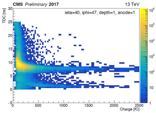
Figure 6.
Arrival time as a function of the charge of hits detected in the HF with upgraded PhotoMultiplier Tubes (PMTs) with dual readout [9].
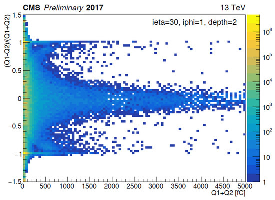
Figure 7.
Charge asymmetry distribution of hits detected in the HF with upgraded PMTs with dual readout [9].
In the HE, the readout previously made with Hybrid PhotoDetectors (HPDs) was completely upgraded with Silicon PhotoMultipliers (SiPMs) [10], which allow for a finer longitudinal segmentation and a photo-detection efficiency improved by a factor of ∼2.5, besides eliminating sources of coherent noise and improving the uniformity of response. Figure 8 shows the improvement in the uniformity of response with the upgraded readout compared to the previous version.
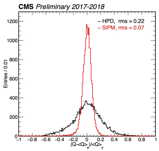
Figure 8.
Distribution of / produced in the Hadron End cap (HE) at the same eta and depth inserting a Co wire-source. The distributions with the previous Hybrid PhotoDetectors (HPDs) and the new Silicon PhotoMultipliers’ (SiPMs) readout are shown [11].
6. The Muon System
The muon system [12] is instrumented with DTs in the barrel up to < 1.2 and with CSCs in the end caps in the region 1.0 < < 2.4 providing precision position measurement and trigger. In addition, RPCs are also present in the barrel and in the end cap up to < 1.8 to provide coarse position measurement and redundant trigger. The muon system’s main goals are to provide efficient muon identification, improve the resolution of the transverse momentum measurement of high muons, and provide a robust stand-alone muon trigger for the bunch crossing assignment.
During Run 2, many changes were performed on the muon system, on the detectors, the High-Level Trigger (HLT) algorithms, and the offline reconstruction, in order to prepare it for higher collision energy and luminosity [13].
Already in 2015, some new stations were added, namely the CSC station ME 4/2 and the RPC stations RE 4/2 and RE4/31, in the region 1.2 < < 1.8 (Figure 9). Their goal is to increase the muon system redundancy in preparation for the LHC high luminosity, so that L1 trigger tracks are met more often and trigger quality cuts are achievable with a reasonable rate also at high luminosity. For similar purposes, in the next few years, three new stations based on Gas Electron Multiplier (GEM) technology will be installed in the forward region of the muon end cap. As the GE1/1 GEM station is the first one scheduled for installation (2019–2020), a slice test made of five chambers covering in total 50 was already installed in the negative muon end cap at the beginning of 2017 as a test before the full installation.
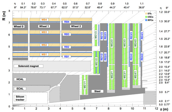
Figure 9.
Schematic drawing of a quadrant of the CMS detectors, including the new Cathode Strip Chamber (CSC) station ME 4/2 and the Resistive Plate Chamber (RPC) stations RE 4/2 and RE4/3 [14]. HCAL, Hadron Calorimeter; DT, Drift Tube.
For the LHC Run 2, the segment algorithm of DTs was changed into the mean-timer algorithm, based on the DT geometry in which layers are half-cell staggered, assuming an almost constant drift velocity and in which the particle crossing time is a free parameter of the segment fit. The new algorithm improved the rejection of -rays and the position resolution. It also provided an excellent measurement of the segment time (∼2-ns time resolution for in-time muons), and it can be used to identify and reject out-of-time muons with delays up to about 10 bunch crossings. Figure 10 shows the comparison of the number of reconstructed muon segments with the previous and new algorithm. The sharpening of the central peak is produced by in-time muons, while among out-of-time muons, the 50-ns spacing between bunch crossings is clearly visible on the right side of the distribution obtained with the mean-timer algorithm.
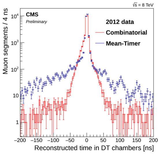
Figure 10.
Number of muon segments for different reconstructed time in the DT chambers, reconstructed with the combinatorial algorithm (red) and the new mean-timer algorithm (blue) [15].
Since November 2017, RPC-only segments have been available in the Level-1 Barrel Muon Track Finder (BMTF) in the first two barrel wheels MB1 and MB2. Previously, segments where reconstructed using either DT and RPC or DT only. The introduction of RPC-only segments led to an improvement of the overall BMTF efficiency of about 0.7% and a reduction of the barrel muon trigger rate of about 3%. In addition, an efficiency improvement up to 2% was observed also in the space between wheels ( 0.25 and 0.85), where the efficiency slightly drops by construction (Figure 11). The overall performance of RPC detectors is stable in terms of efficiency, bunch crossing distribution and cluster size.
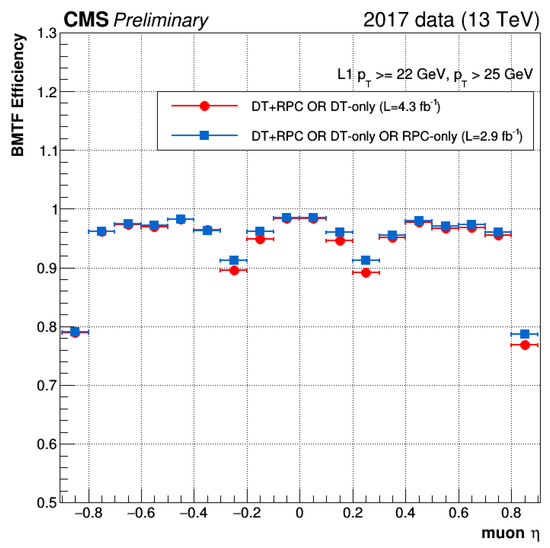
Figure 11.
Barrel Muon Track Finder (BMTF) trigger efficiency as a function of the muon pseudorapidity for segments built only from DT or DT+RPC (red) and from DT, DT + RPC, and RPC only (blue) [16].
Finally, CSCs run with very high efficiency and trigger primitive efficiency, with stable time and spatial resolution within the system’s design specifications. Figure 12 shows an example of CSC detection efficiency measured from 2016 data.
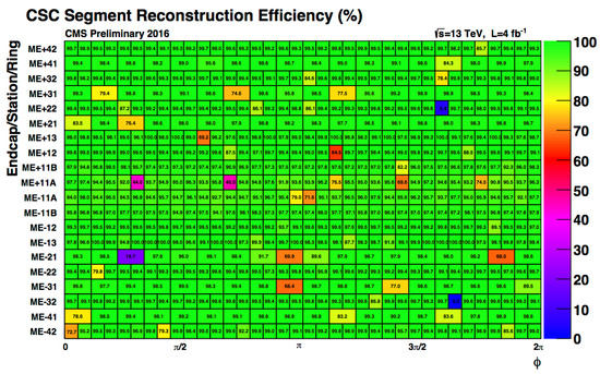
Figure 12.
CSC segment reconstruction efficiency measured from 2016 data. Bins with lower efficiency are due to known hardware problems [17].
The overall muon system performance [14] in Run 2 compared to data collected in 2010 at a center-of-mass energy of 7 TeV and an instantaneous luminosity approximately 40-times smaller is in general at least as good as or even better than in 2010. The detector performance is within the design specifications, and the muon reconstruction results are well reproduced by Monte Carlo simulation.
7. Summary
Before the beginning of and during Run 2, CMS started several upgrades of its detectors, trigger system, electronics, and readout systems in order to get prepared for the LHC high luminosity. The upgrades already started showing the benefits of the detector performance. During Run 2, in July 2018, the LHC delivered collisions with a peak luminosity of about 2 × 10 cm s, corresponding to an event pileup greater than 55. CMS is running well with very good recording efficiency and a high and stable fraction of active channels.
Conflicts of Interest
The authors declare no conflict of interest.
References
- CMS Collaboration. The CMS experiment at the CERN LHC. J. Instrum. 2008, 3, S08004. [Google Scholar] [CrossRef]
- The Phase-2 Upgrade of the CMS Tracker. Available online: https://cds.cern.ch/record/2272264 (accessed on 7 January 2019).
- Sonneveld, J. Commissioning and first results from the CMS phase 1 upgrade pixel detector. In Proceedings of the 26th International Workshop on Vertex Detectors, Las Caldas, Asturias, Spain, 10–15 September 2017. PoS(Vertex 2017)018. [Google Scholar]
- CMS Tracker Detector Performance Results. Available online: https://twiki.cern.ch/twiki/bin/view/CMSPublic/DPGResultsTRK (accessed on 7 January 2019).
- The CMS Electromagnetic Calorimeter Project: Technical Design Report. Available online: https://cds.cern.ch/record/349375 (accessed on 7 January 2019).
- Teixeira de Lima, R. Overview of Energy Reconstruction, and Electron and Photon Performances with the CMS ECAL in Run II. J. Phys. Conf. Ser. 2017, 928, 012005. [Google Scholar] [CrossRef]
- CMS Collaboration. CMS ECAL with 2017 Data, CMS-DP-2018-015, CERN-CMS-DP-2018-015. 2018. Available online: https://cds.cern.ch/record/2319285 (accessed on 7 January 2019).
- The Hadron Calorimeter Technical Design Report. Available online: https://cds.cern.ch/record/357153 (accessed on 7 January 2019).
- CMS Collaboration. Noise in Phase 1 HF Detector in 2017, CMS-DP-2017-034. 2017. Available online: https://cds.cern.ch/record/2281147 (accessed on 7 January 2019).
- CMS Technical Design Report for the Phase 1 Upgrade of the Hadron Calorimeter. Available online: https://cds.cern.ch/record/1481837 (accessed on 7 January 2019).
- CMS Collaboration. Results Related to the Phase1 HE Upgrade, CMS-DP-2018-019, CERN-CMS-DP-2018-019. 2018. Available online: https://cds.cern.ch/record/2320857 (accessed on 7 January 2019).
- CMS Collaboration. The CMS muon system. Nucl. Instrum. Methods Phys. Res. A 2000, 446, 366–372. [Google Scholar] [CrossRef]
- The Phase-2 Upgrade of the CMS Muon Detectors. Available online: https://cds.cern.ch/record/2283189 (accessed on 7 January 2019).
- CMS Collaboration. Performance of the CMS muon detector and muon reconstruction with proton-proton collisions at = 13 TeV. J. Instrum. 2018, 13, 1–56. [Google Scholar] [CrossRef]
- Abbiendi, G. The CMS muon system in Run2: Preparation, status and first results. In Proceedings of the European Physical Society Conference on High Energy Physics (EPS-HEP 2015), Vienna, Austria, 22–29 July 2015; Volume 234, p. 237. [Google Scholar] [CrossRef]
- Shah, M.A.; Hadjiska, R. The CMS RPC Detector Performance and Stability during LHC RUN-2. In Proceedings of the 14th Workshop on Resistive Plate Chambers and Related Detectors (RPC2018), Puerto Vallarta, Mexico, 19–23 February 2018. [Google Scholar]
- CMS Collaboration. Performance of the CMS Muon Detectors in 2016 Collision Runs, CMS-DP-2016-046, CERN-CMS-DP-2016-046. 2016. Available online: http://cds.cern.ch/record/2202964 (accessed on 7 January 2019).
| 1 | Refer to [1] for the nomenclature of the CMS muon system. |
© 2019 by the author. Licensee MDPI, Basel, Switzerland. This article is an open access article distributed under the terms and conditions of the Creative Commons Attribution (CC BY) license (http://creativecommons.org/licenses/by/4.0/).