Article

Toward Automated Coronal Observations: A New Integrated System Based on the Lijiang 10 cm Coronagraph

1
Yunnan Observatories, Chinese Academy of Sciences, Kunming 650216, China
2
Yunnan Key Laboratory of Solar Physics and Space Science, Kunming 650216, China
3
College of Physical Science and Technology, Southwest Jiaotong University, Chengdu 611756, China
*
Author to whom correspondence should be addressed.
Universe 2025, 11(5), 154; https://doi.org/10.3390/universe11050154
Submission received: 20 December 2024 / Revised: 1 April 2025 / Accepted: 22 April 2025 / Published: 7 May 2025

Abstract

:
About ten years ago, we established the first coronagraph that has been continuously operating on the high plateau of western China. This coronagraph is an internal occulting, 10 cm aperture instrument, installed at Lijiang Station through a collaboration with the Norikura Station of the National Astronomical Observatory of Japan. To ensure high efficiency in current and future coronal observations, developing integrated observation systems is essential for reliable, autonomous, and remote operation of coronagraphs. This paper introduces an advanced integrated observation and control system, based on the Lijiang 10 cm coronagraph. The coronagraph focuses on the observations for the solar inner corona, capturing the coronal green-line emission within a field range from 1.03 R to 2.5 R . To enhance the observational precision and efficiency, a comprehensive integrated system has been designed, incorporating various subsystems, including precise pointing and tracking mechanisms, a multi-band filter system, a protective dome system, and a robust data storage infrastructure. This paper details the hardware architecture and software frameworks supporting each subsystem. Results from extended operational testing confirm the stability of the system, its capacity for autonomous and remote observations, and significant improvements in the automation and efficiency of coronal imaging. The automated observation system will be further improved and used for our future coronagraphs to be developed for coronal magnetism diagnosis.

1. Introduction

Observing the corona and monitoring its dynamic activities is a routine task. The corona’s magnetic environment, characterized by extremely high temperatures and low plasma density, can cause various solar eruptions that serve as source regions for space weather. Coronagraphs have been utilized to diagnose the corona for several decades. Only recently have we started regular coronal observations at Lijiang Station using a Norikura 10 cm coronagraph [1,2], which was relocated there in 2013 for observing the coronal green line (530.3 nm wavelength). In Figure 1, the right frame shows the temporary dome used for the first couple of years for the 10 cm coronagraph in the farmland close to Lijiang Station (26°41.7′ N, 100 °1.8′ E, alt. 3200 m), while the left one shows the current new building inside the station for the coronagraph, which features a much better power supply, a better internet system, and other better available logistics. The first light was successfully taken on 25 October 2013 (Figure 2) in which the bright inner coronal structure can be clearly seen above the occulter limb (about 1.03 R from solar disk center). For the telescope system operation, a compact graphical user interface (GUI) was supplied by our Norikura colleagues for mainly controlling and adjusting the CCD and the filter systems. However, the GUI functions are obviously limited since many other important parts are not incorporated into them, requiring additional labor for tasks such as manual dome rotation and environmental monitoring. Therefore, to ensure highly efficient current and future coronal observations on remote high plateaus, developing integrated observation systems for future ground-based coronagraphs is an immediate priority.
Usually, telescope observation systems comprise numerous interconnected subsystems, including pointing and tracking mechanisms, dome systems, data acquisition modules, and others. Advances in automation and computing technologies have led to a growing reliance on integrated observation systems, which efficiently coordinate these subsystems to execute complex observational tasks such as target selection, precise pointing and tracking, wavelength band selection, and data collection. This integration significantly enhances the accuracy, efficiency, and usability of telescopes [3]. For instance, Large Sky Area Multi-Object Fiber Spectroscopic Telescope (LAMOST)’s Observation Control System (OCS) [4,5] exemplifies a multilayered, hybrid centralized and decentralized control architecture, effectively integrating software and hardware interfaces across subsystems and operational modules to enable automated, high-precision observations. The software in these integrated systems not only manages and processes the vast volumes of data generated but also provides an intuitive user interface, facilitating easy telescope control and supporting remote operations. This comprehensive design reduces the need for specialized operators and increases operational flexibility. Consequently, integrated observation systems are essential for the reliable and autonomous operation of telescopes, supporting both routine and remote observational capabilities.
Coronal observation serves as an essential methodology for investigating solar activity and space weather phenomena, with the coronagraph functioning as the primary telescope system employed for these observations [6,7]. The coronagraph operates based on the principle of “occulting”, utilizing an occulter to obstruct the central region of the solar disk, thereby enabling the observation of the fainter coronal light that surrounds the Sun [8]. Despite the relatively singular focus of the coronagraph’s observational target, its distinctive structure introduces complexities into the overall control system of the telescope. The Yunnan Observatories coronagraph Green-line Imaging System (YOGIS) [2,9,10,11], developed through a collaborative effort between Yunnan Observatories and the National Astronomical Observatory of Japan, is designed to observe the coronal green line within the radial range of 1.03 R to 2.5 R . Its predecessor, the Norikura Green-line Imaging System (NOGIS) [1], was situated at the National Astronomical Observatory of Japan. Upon the coronagraph’s relocation to Gaomeigu Observatory in Lijiang [12,13], only the optical system of the telescope was operational. To enable routine observations with the coronagraph, it became imperative to design and construct supporting subsystems tailored to the observational characteristics of the corona. These subsystems include the telescope’s pointing and tracking system, filter control system, dome protection system, data acquisition and processing system, and remote observation system. This study commences with an introduction to the overall architecture, subsystem classification, and composition of YOGIS. It subsequently provides a detailed examination of the hardware components and control interfaces associated with each subsystem. Finally, a modular software design has been developed for the hardware of each subsystem, resulting in the construction of a visualized integrated observation system capable of responding to remote observation commands. Following an extended period of operational observations, the integrated OCS has demonstrated stability, effectively facilitating both regular and remote observations of the coronagraph. This development has significantly enhanced observational efficiency and automation while substantially alleviating the operational burden on observers.

2. System Components of YOGIS

Similar to traditional telescope observation systems, compatible subsystems had to be developed around the telescope to form a comprehensive observation system. Consequently, improvements were made to the Lyot filter control system, originally based on the primary mirror of the NOGIS coronagraph. Additionally, a multi-axis control system was developed, and a fork-arm equatorial mount was acquired. An observation platform, comprising the dome, base pier, associated buildings, and auxiliary observational instruments, was also constructed. This culminated in the formation of the current YOGIS coronal observation system. Figure 3 illustrates a schematic of the entire YOGIS observation platform and control system. Currently, the hardware configuration of YOGIS largely meets the requirements for autonomous and remote observations. To achieve autonomous observation across the system, it is essential to integrate the control of various types of equipment. Based on the characteristics of YOGIS, the hardware system has been divided into three components: the pointing and tracking system, the telescope system, and the auxiliary system (Figure 4). While most of the equipment was custom-designed to meet observational requirements, several components are commercially available products.

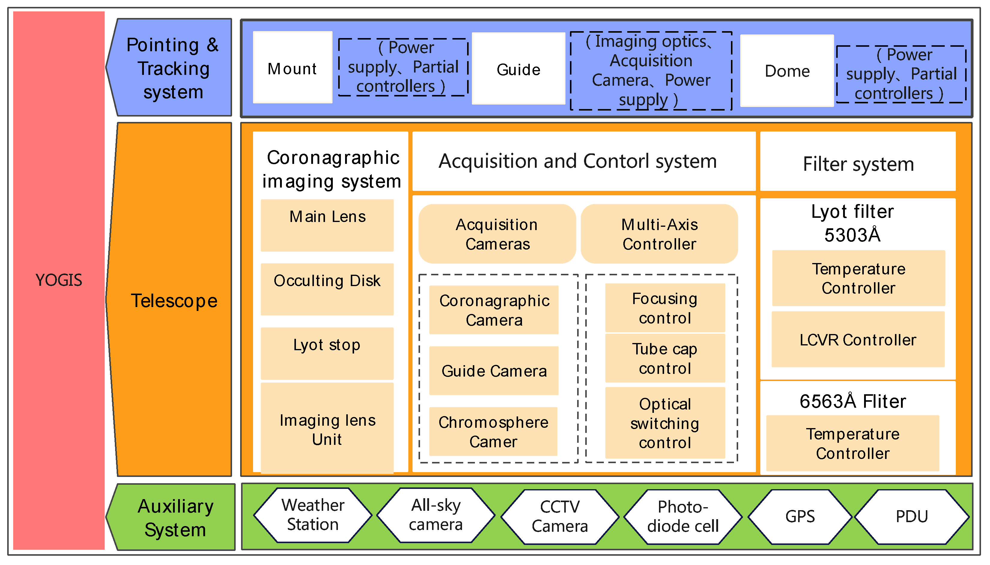
2.1. Telescope System

The telescope system serves as the fundamental component of YOGIS, comprising primarily the optical system, acquisition and control system, and filter system.
  • Optical System: The structural diagram of the YOGIS telescope’s optical system is presented in image C at the bottom of Figure 3. This telescope utilizes the classical optical configuration of a Lyot-type coronagraph. The effective aperture of the telescope measures 10 cm, with a primary mirror focal length of 149 cm. YOGIS is designed to observe wavelengths where the coronal signal is pronounced, particularly the Fe XIV line (coronal green line, central wavelength 5303 Å), and it is also capable of observing prominences at a central wavelength of 6563 Å through the use of a spectroscopic prism. Additionally, an optical pathway is implemented to monitor the Sun’s position relative to the occulter, thereby ensuring precise coronal observations. The optical system is similar to that of NOGIS, and enhancements have been made to its electronic control to facilitate autonomous integrated observation.
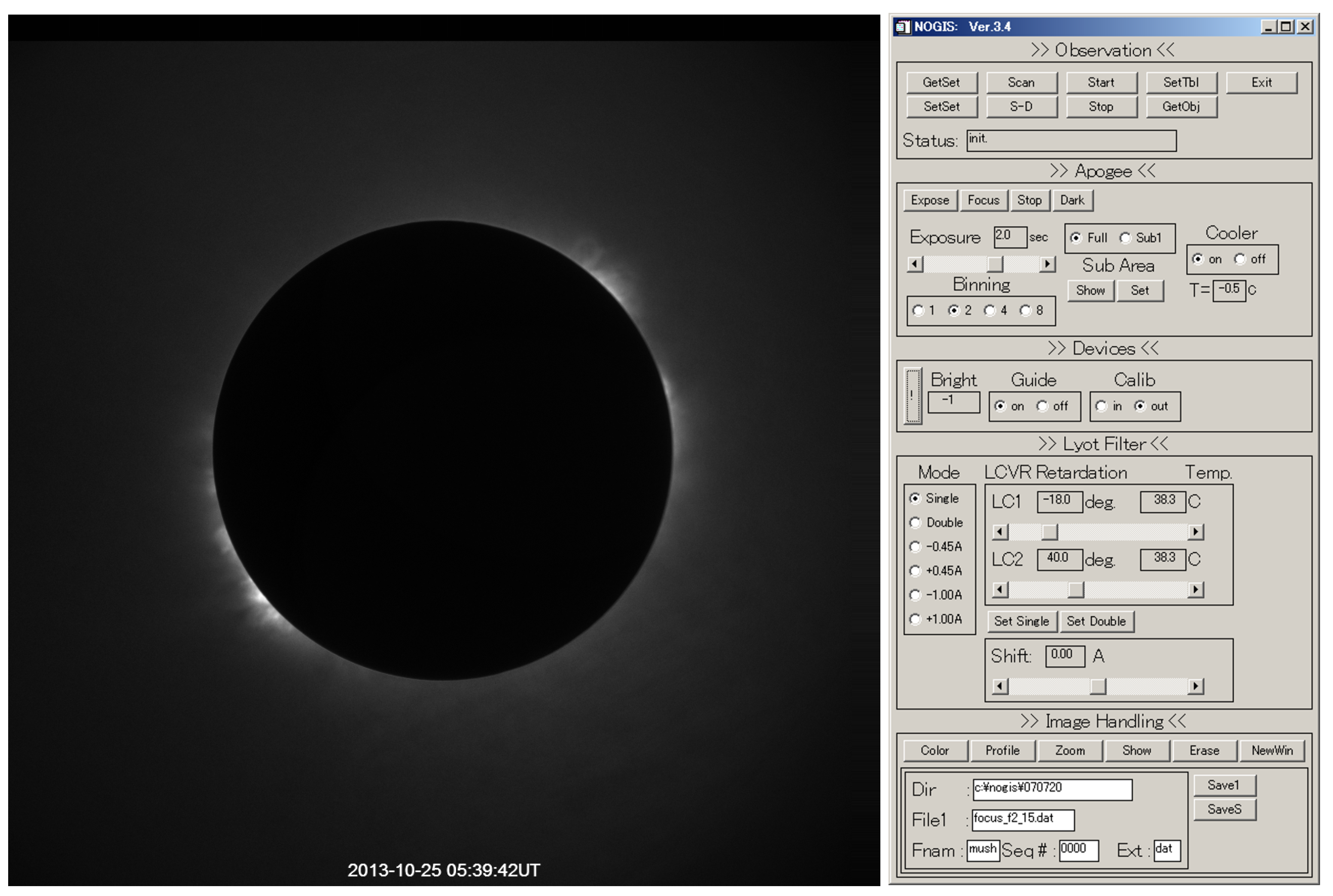
  • Filter System: The telescope system comprises two narrow-band filters: a Lyot filter with a central wavelength of 5303 Å and a Daystar brand Quantum series filter with a central wavelength of 6563 Å. The Lyot filter serves as a fundamental component of the telescope system, providing the narrow-band (typically∼1 Å) central wavelength necessary for coronagraphic observations. Additionally, it facilitates the tuning of the passband wavelength, enabling multi-band observation of spectral lines and effective subtraction of sky background, which is essential for achieving a higher signal-to-noise ratio in coronal imaging. The Full Width at Half Maximum (FWHM) of the Lyot filter’s transmission band is 1 Å, and wavelength tuning is achieved through a Liquid Crystal Variable Retarder (LCVR), which has a tuning range of −2 Å to +2 Å and a tuning time of less than 60 ms. Detailed designs of the Lyot filter will be discussed in a subsequent study. Based on the characteristics of the Lyot filter, a controller was developed for tuning the transmission band wavelength. This controller functions as a waveform generator that regulates LCVR’s delay angle using varying amplitudes of a 2 kHz square wave, thereby enabling the adjustment of the central wavelength of the passband. Additionally, a temperature controller has been implemented for the electronic regulation of the Lyot filter. In contrast, the other solar chromosphere filter is a well-established commercial product that requires only temperature control and does not necessitate real-time adjustments.
  • Acquisition and Control System: The acquisition system is fundamentally composed of three imaging cameras. The primary channel serves as the main camera for capturing coronagraph images, while the second channel is designated for capturing images of solar prominences. The third channel is responsible for monitoring the Sun’s position in relation to the occulter. The specific parameters of these three cameras are detailed in Table 1. Data transfer and parameter control for the cameras are facilitated using a USB 3.0 interface; consequently, a fiber-optic USB 3.0 hub has been installed on the telescope to effectively manage the data acquisition and control processes for all three cameras.
    To enhance the integrated control of the entire telescope system, this study developed a multi-axis controller that supersedes the previous manual adjustment mechanisms. This multi-axis controller is organized into four control channels. The first channel is responsible for the operation of the telescope’s mirror cover, which can be substituted with a flat field plate for flat field imaging. The second channel manages the focusing of the primary mirror, while the third channel oversees the switching of the optical path; this switching allows for imaging of the primary mirror to evaluate the extent of dust accumulation. The fourth channel is dedicated to the focusing of the rear-end imaging system. The design of the multi-axis controller is tailored to meet the observational requirements of YOGIS, employing a GALIL DMC-500 EtherCAT Master multi-axis motion controller. This controller is connected to the control computer using an Ethernet port, thereby facilitating efficient control of the four motors.

2.2. Pointing and Tracking System

The pointing and tracking system serves as a crucial platform for YOGIS observations, facilitating extended and accurate observations of the solar corona. This system is fundamentally categorized into three components: the dome, the equatorial mount, and the closed-loop guiding system.
  • Dome: The dome serves as a protective structure for the telescope, shielding it from external elements like precipitation and particulate matter, while also reducing wind loading effects on the instruments. Due to the consistently low average wind speeds recorded throughout the year at Gaomeigu Observatory [12], a full-sky dome devoid of a skylight has been implemented. This design choice eliminates the necessity for real-time adjustments of the skylight position and enhances Dome-Seeing. The fabrication of the dome was contracted to a third-party manufacturer, whereas the design of the electronic control system was conducted internally. As a full-sky structure, the electronic control system is relatively simple. A Programmable Logic Controller (PLC) serves as the foundational control module, facilitating communication with the control host through a Transmission Control Protocol/Internet Protocol (TCP/IP) communication protocol.
  • Equatorial Mount: The equatorial mount serves as the fundamental component for the pointing and tracking capabilities of the coronagraph. Specifically designed to meet the demands of coronal observation, it incorporates a fork-arm mechanical structure coupled with a worm-and-wheel transmission system, which enables solar tracking without necessitating a flip at culmination. The mechanical and electronic control systems of the equatorial mount were developed by the Nanjing Institute of Astronomical Optics and Technology, part of the National Astronomical Observatories, Chinese Academy of Sciences (CAS). This institution also provided the control interfaces and communication protocols. To facilitate integrated observation, modifications and enhancements to the software drivers were implemented based on the hardware provided by the manufacturer. Similar to the dome, the equatorial mount communicates with the control host through a TCP/IP communication protocol.
  • Guide System: The guiding system employs full-disk solar image positioning techniques. First, it calculates the positional deviation of the solar center based on the full-disk images obtained from the guide mirror. Secondly, it fine-tunes the movement of the equatorial mount utilizing a Proportional–Integral–Derivative (PID) algorithm, thereby establishing a closed-loop precision tracking system. The development of the control mechanism for the guiding system was conducted independently by the authors. Following the processes of polar alignment and closed-loop tracking adjustments, the entire observational system achieves a pointing accuracy of 20″ and a tracking accuracy exceeding 5″ over a duration of 10 min, thereby fully satisfying the requirements for precise coronal observation. The guide mirror is affixed to the coronagraph, with its optical axis aligned parallel to that of the coronagraph. It primarily operates a GigE interface industrial camera, which communicates with the control computer through an Ethernet interface.

2.3. Auxiliary System

The auxiliary system provides essential calibration data and header file information required for coronal observations, thereby facilitating the optimal functioning of the telescope. In response to the observational requirements of YOGIS, this study implemented a meteorological station, an all-sky camera, a solar photometer, a GPS time server, a power management system, and surveillance cameras as supplementary observational equipment.
  • Meteorological Station: The Davis-Vantage Pro2 6152 wireless standard meteorological station was directly purchased. This system functions as an integrated automatic meteorological station, capable of measuring various parameters including wind speed, wind direction, air temperature, relative humidity, atmospheric pressure, and rainfall. Data are automatically recorded at predetermined intervals. The fundamental configuration comprises a wireless meteorological station main unit and a wireless console equipped with software. The main unit is responsible for measuring meteorological parameters and wirelessly transmitting the data to the console, which subsequently connects to a control computer using an RS232 serial port. The software facilitates real-time display and computation of meteorological parameters, data storage, and the incorporation of essential meteorological parameter data into the header files of the main camera images.
  • All-Sky Camera: The system provides real-time, intuitive visualizations of the cloud distribution and sunlight conditions across the entire sky, thereby facilitating optimal timing for observational activities. The all-sky camera is primarily composed of a fisheye lens and a ZWO-ASI178 camera, utilizing a 2.5 mm industrial lens. An acrylic protective cover was installed in front of the lens. However, over time, this cover became oxidized and discolored, adversely impacting image quality. Consequently, the cover was removed, and the camera and lens were waterproofed, which resulted in a significant enhancement of image quality. The interface connecting the camera to the control computer is established through a direct USB connection. Furthermore, a dedicated website has been developed for the all-sky camera, enabling users to monitor cloud cover information at the observation site from any location at any time.
  • Solar Photometer: An essential device for intensity calibration in coronal observations, this solar photometer is designed to calibrate the intensity between the solar center and the corona. Specifically developed for the observation requirements at 5303 Å, the photometer employs a 530 nm filter in conjunction with a neutral density filter at the front end. It features a bandwidth of 10 nm and a transmission rate of 1/10,000, with a photodiode positioned at the rear for the collection of intensity data. The optical path of the photometer is aligned parallel to the main optical path of the coronagraph, facilitating the real-time acquisition of relative intensity values at the solar center.
  • GPS Time Server: A GPS-based Network Time Protocol (NTP) server was procured to acquire standard time signals from GPS satellites. This server disseminates the time information through multiple interface types to devices within the automated system that necessitate accurate time data, including the control computer, dome, equatorial mount, event sequence recorder, and data processing computer. This configuration facilitates comprehensive time synchronization across the entire system.
  • Power Manager: A remotely controllable Power Distribution Unit (PDU, Tesin-Sr900 series) was also directly purchased, enabling convenient control of power switches for various systems. The PDU is configured with dual routing; the first route manages power supply to devices located within the dome, while the second route is designated for the control room and additional devices.
  • Surveillance Cameras: The primary function of the surveillance system is to monitor the operational status of the telescope during coronal observations, as well as the environmental conditions both inside and outside the observatory. Two surveillance cameras were installed in this study: the first is positioned within the dome to provide real-time monitoring of the coronagraph’s operational posture, while the second is located externally to observe the surrounding environment of the dome and its vicinity. These surveillance cameras are advanced products from Hikvision, which facilitate image sharing across multiple devices and computers through an Ethernet network.

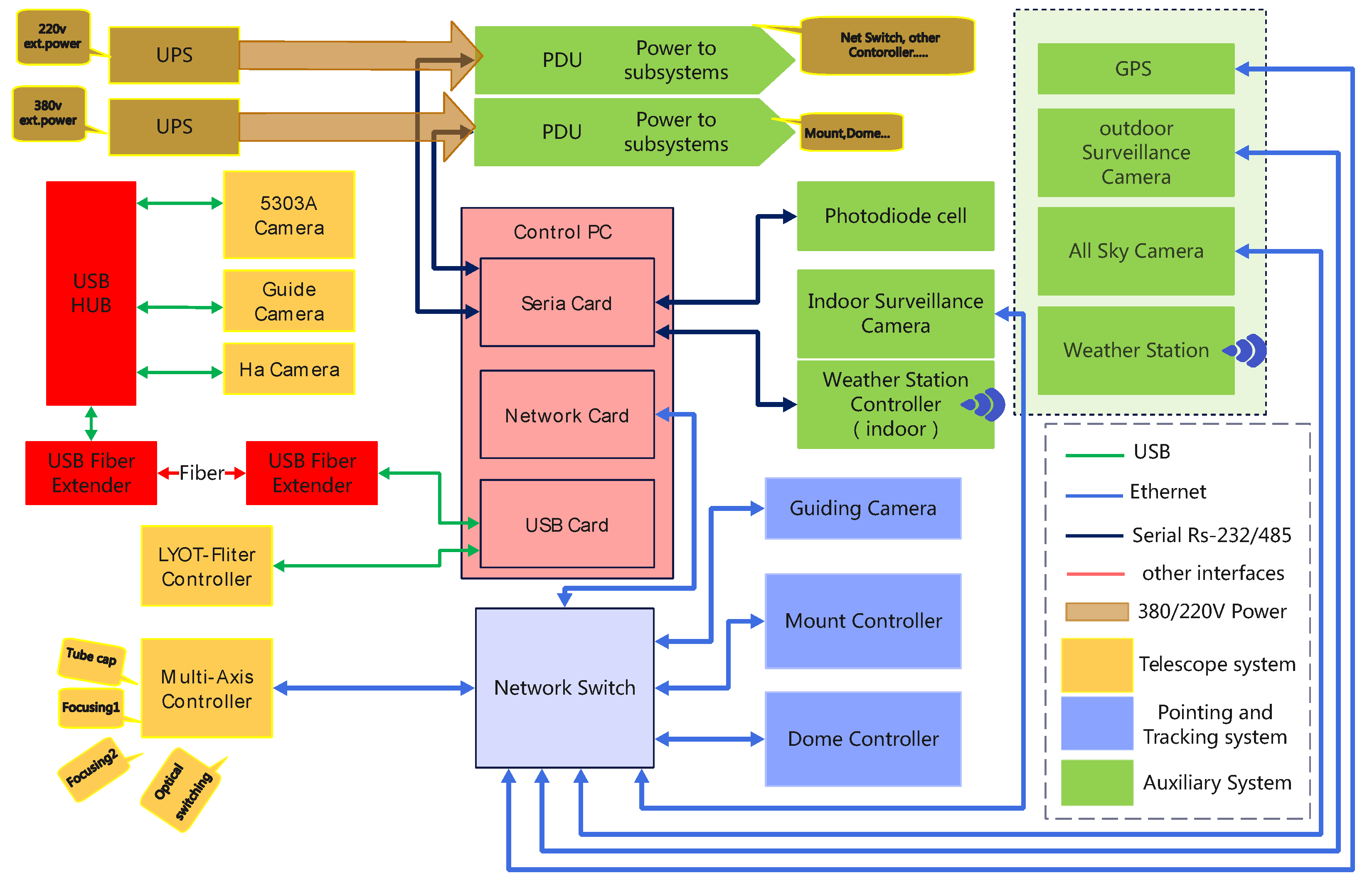
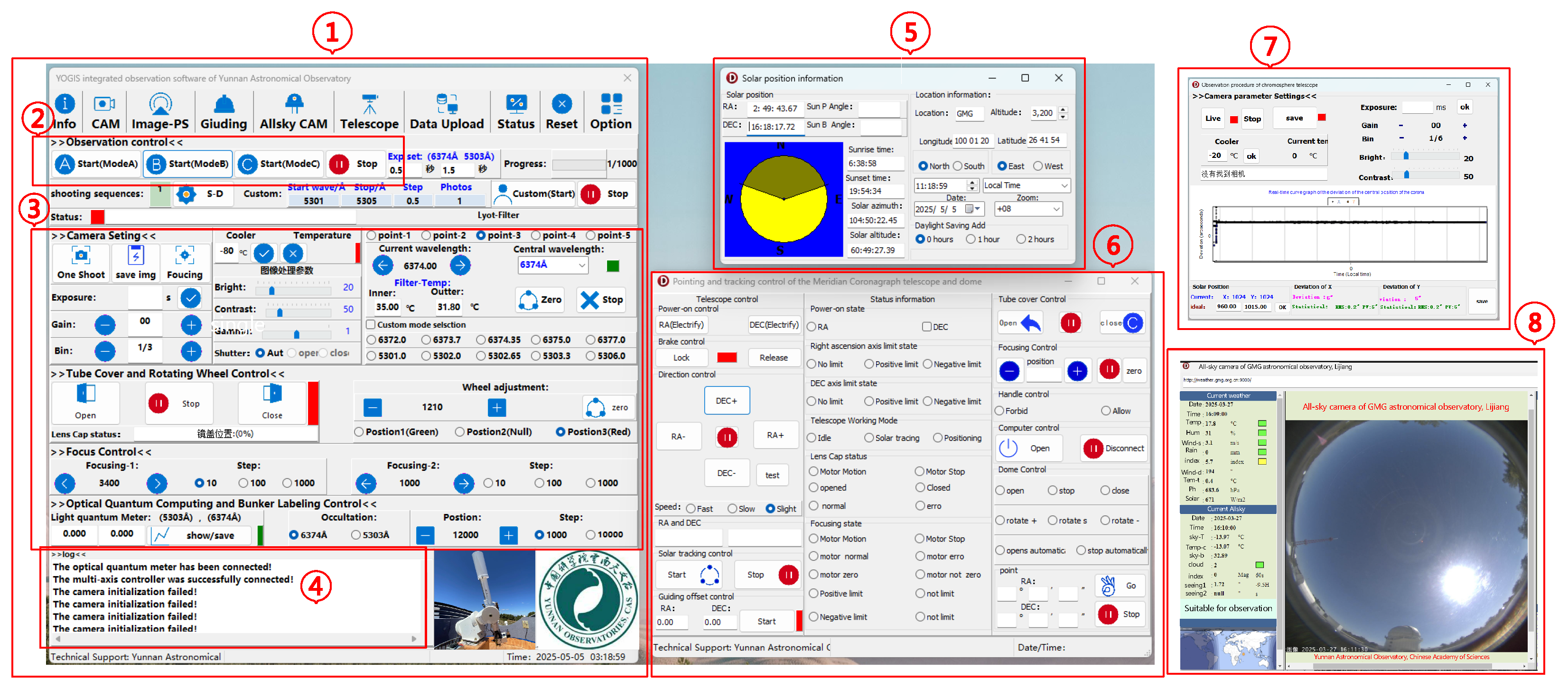
2.4. YOGIS Integrated System Interface Configuration

Figure 5 depicts the interface configuration among the various hardware components of YOGIS and the control computer. Hardware devices primarily connect to the control computer via USB, serial, and network interfaces. While these interfaces are standard in industrial control systems, achieving integrated control of the entire hardware system necessitates a modular software design for each hardware component. In this context, the Astronomy Common Object Model (ASCOM) platform [14] will be employed for the modular software design of the hardware, with specific implementations detailed in the subsequent section on software design. Certain devices are utilized only for auxiliary observations and do not require integration into the overall observation workflow. Therefore, they do not possess separate modular designs. Instead, software is developed as needed to facilitate the display or storage of the requisite data.

3. Software Design

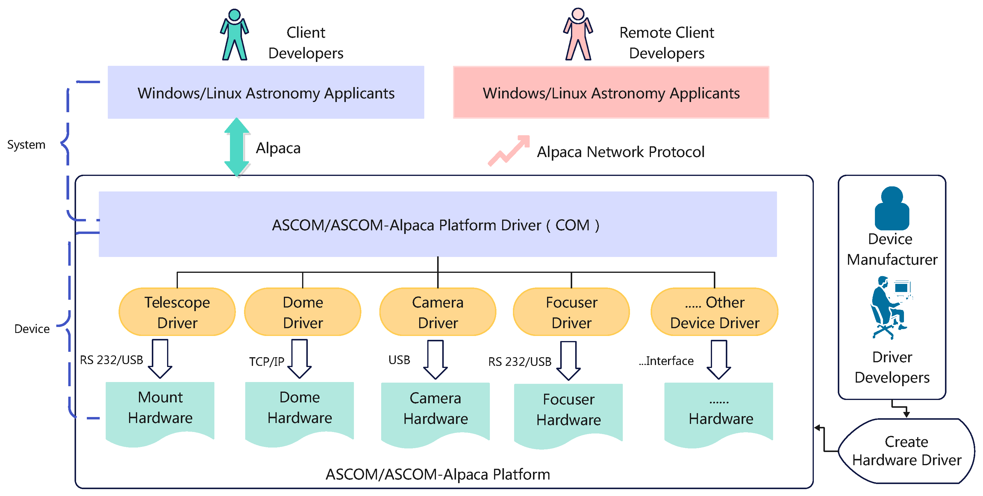
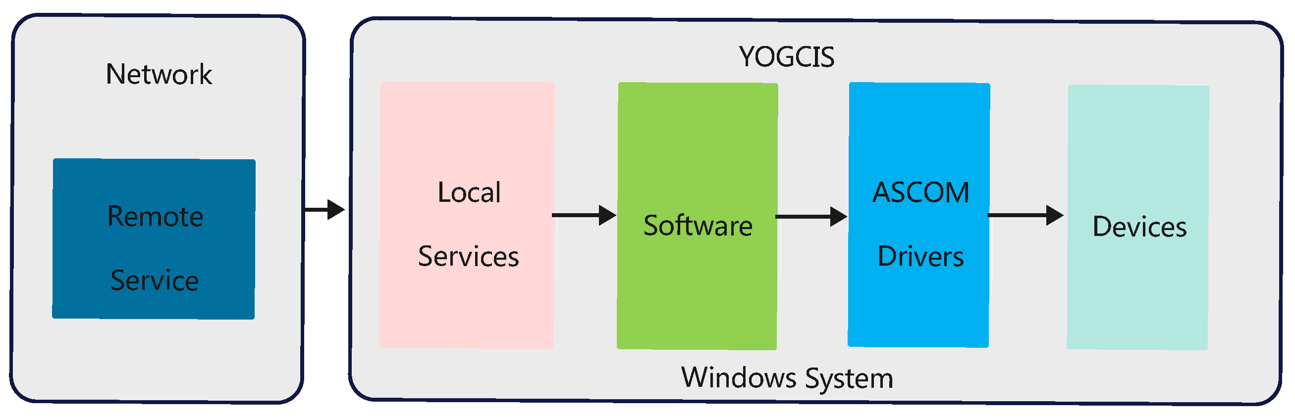
3.1. Selection of Framework and Platform

As shown in Figure 5, the YOGIS system, despite its relatively specific observational focus, includes a complex array of hardware devices. This study considered developing separate control software for each hardware system. However, this strategy would have rendered the entire observational system cumbersome, redundant, and unsuitable for autonomous observation and remote control, which are essential for high-altitude astronomical observations. ASCOM, a software interface protocol designed for small to medium-sized telescope systems and astronomy enthusiasts, provides a solution to this challenge [15]. By implementing an interface driver layer between hardware and software, developers are required to supply only ASCOM-compliant drivers for telescopes, cameras, and filters, thereby ensuring seamless integration with any ASCOM-compatible control software [16,17]. This approach significantly enhances the flexibility of device expansion and software updates, thereby improving the integration capabilities of astronomical equipment. The acquired cameras are equipped with complete ASCOM drivers. If certain hardware devices lack ASCOM drivers, drivers that comply with ASCOM standards can be developed. Additionally, the latest ASCOM architecture, known as ASCOM-Alpaca, builds upon the original framework by incorporating technologies such as Representational State Transfer (REST), JavaScript Object Notation (JSON), Hypertext Transfer Protocol (HTTP), and TCP/IP. This development facilitates communication between applications and devices over networks, positioning Alpaca as a network protocol that enables ASCOM-standard applications and devices to interact. Therefore, this development allows astronomical applications across various operating systems to discover and control astronomical devices over the network, thereby significantly enhancing the compatibility for remote control applications. Figure 6 illustrates the development architecture of the ASCOM platform. By writing ASCOM software drivers for various hardware and installing them on the ASCOM platform, devices can be controlled from different operating systems or remotely. This streamlined process greatly supports the initiatives in modular design, integrated control, and remote observation.
The ASCOM-Alpaca platform was selected as the foundation for communication with hardware devices, employing a layered architecture in Figure 7. This approach facilitates integrated control and observation of the entire system within the Windows environment. The programming languages utilized include a combination of C sharp and Delphi Pascal. C sharp is primarily tasked with the development of ASCOM-Alpaca drivers, while Delphi Pascal is responsible for the implementation of the integrated observation software interface and the functionalities of various sub-modules. For guidance on the development of ASCOM-Alpaca drivers, one may refer to the examples available in the official ASCOM website forums [14].

3.2. Software Concept

Figure 8 depicts the software architecture of the integrated observation system developed for YOGIS. A modular design has been implemented, segmenting the integrated observation software according to different functional requirements into the following components: the main control module, the telescope operation module, the auxiliary information module, the remote service module, and additional operational modules. Each module employs multithreaded programming, thereby facilitating parallel operations. The main module is predominantly utilized during routine observations; upon completion of solar pointing and tracking, the selection of various observation modes within this module enables the automatic execution of coronal observations across multiple wavebands, as well as the storage of Flexible Image Transport System (FITS) images. The telescope control module computes solar coordinates in real-time, utilizing Global Positioning System (GPS) time and location data. By simply selecting “Point to Sun” within the module, the telescope is directed to align with the Sun. Once a full-disk solar image is acquired, the system automatically transitions to closed-loop tracking mode, thereby enabling rapid coronal tracking observations. Furthermore, the underlying hardware control is facilitated through ASCOM drivers, which promote seamless data sharing among multiple devices. For remote operation, three methods are available: browser control mode utilizing ASCOM-Alpaca drivers, control using ActiveMQ message queues, and remote desktop access. Currently, the remote desktop method is regarded as the simplest and most user-friendly option.

4. Autonomous Observation

For the autonomous observation implementation of YOGIS, we systematically analyzed observation requirements and subsequently established multiple observation modalities with associated operational protocols. Operators can select appropriate observation modes via the master control console, enabling the integrated observation system to automatically retrieve and implement predefined plans from the central database. Additionally, equipment status monitoring and alarm mechanisms are critical for the automatic control of YOGIS. The integrated observation system software performs real-time monitoring of weather and equipment status, with issues highlighted by red warning indicators on the status display interface.

4.1. Observation Modes and Observation Process

For YOGIS, there are four primary observational bands: the green line core band (single), the sky background band (double), the left wing band (−0.45 Å), and the right wing band (+0.45 Å). The two wing bands are utilized for measurements of the Doppler velocity field. There are three observation modes. Mode A, the standard observation mode, cycles through all four bands to produce a comprehensive dataset. Mode B, or rapid mode, integrates the single and double bands. Mode C, designated as the engineering debug mode, is primarily used for scanning the line core band. Figure 9 illustrates an illustration of the automatic observation process utilized by YOGIS. After completing initial preparations, the system transitions into an automated cyclic observation mode, which proceeds as follows:
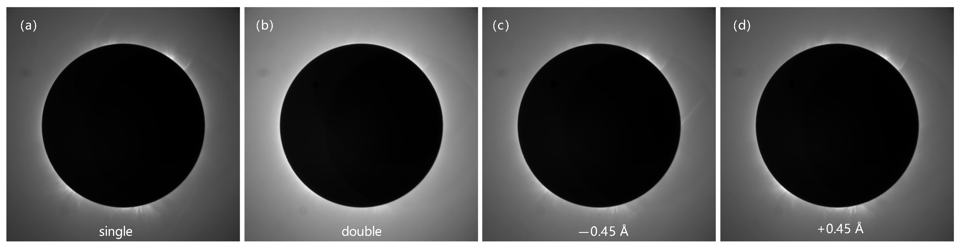
  • Once aligned with the Sun, a preliminary capture in the single-band wavelength is performed to assess image signal strength. Based on this assessment, the system automatically adjusts exposure time, typically ranging from 500 ms to 2 s.
  • After exposure settings are optimized, rapid captures in both the single and double bands are taken. These images are then subtracted to create an S-D image, effectively removing the sky background. Analysis of S-D image identifies regions of interest in coronal activity.
  • With the regions of interest established, the system controls the Lyot filter and camera to sequentially capture data across all four observation bands. For each image, relevant metadata—including solar photometer readings, solar center coordinates, exposure settings, and meteorological parameters—are recorded in the respective FITS files, with a log entry generated for each storage event.
  • Upon completion of the four-band capture sequence, the coronal image is calibrated using the formula I 5303 = ( I 0 + I 0.45 + I + 0.45 ) / 3 ( r 0 + r 0.45 + r + 0.45 ) × I ± 2 to produce a calibrated coronal image, where I 5303 represents the calibrated coronal image and I 0 , I 0.45 , I + 0.45 , and I ± 2 represent the images captured in the four bands; r 0 , r 0.45 , and r + 0.45 represent the calibration coefficients. Following the repetition of the capture process across all four spectral bands three times and the subsequent averaging of the results, the final image designated for storage at Level 0 is produced. Additionally, the image data and corresponding header information are stored in a separate FITS file, as mandated. The calibrated and processed images are presented in a different window. Given that an LCVR is employed for the wavelength tuning of the filter, the switching time for the passband wavelength is notably brief (less than 60 ms). Consequently, the acquisition of a complete set of images typically requires less than 30 s.
  • Steps (1) through (4) are repeated to establish the standard observation cycle, allowing continuous and automated coronal observation.
The preceding description primarily delineates the procedure for conducting regular automatic observations. Each observation mode procedure has been solidified within the database, enabling observers to select the appropriate mode according to their specific observation requirements directly through the main interface. As demonstrated in Figure 10, the primary control interface of YOGIS is presented within the boxed area labeled ‘1’, while the observation mode selection can be executed by clicking the button located in the boxed area labeled ‘2’ on the main interface. It does not elaborate on flat-field and dark-field imaging, nor on closed-loop guiding, as these are fundamental operations within the realm of astronomical observations.

4.2. Status Monitor and Alarm Mechanism

The implementation of equipment status monitoring and alarm mechanisms for critical components—including telescope pointing accuracy, tracking stability, filter wheel positioning, camera exposure parameters, and ambient meteorological conditions—constitutes a fundamental infrastructure for automated astronomical observation systems. This integrated safeguard framework enables real-time closed-loop feedback during unattended operations, effectively preventing mechanical failures through predictive diagnostics while ensuring data acquisition integrity through environmental threshold enforcement.
The monitoring and alert system of YOGIS is structured into three layers. The bottom layer is the sampling layer, which corresponds to various underlying devices. This layer samples each status and its corresponding value, providing a unified interface for the observation control layer. The middle layer consists of the data manager and actuator, where the data manager is responsible for collecting and recording values while the actuator handles partial status changes. The top layer includes both a local monitoring client and a web-based remote user interface, which display real-time status/alarm information and provide manual operation interfaces. As indicated by the 3–8 rectangular box in Figure 10, the real-time status displays of key modules such as camera, filter, dome, telescope position, guiding, and weather conditions are presented.
Critical state parameters are assigned alarm thresholds partitioned into three severity levels: low, medium, and high. The software system initiates predefined operational protocols according to threshold breach severity to ensure equipment integrity and data quality, augmented by differential color-coded visual alerts in the control interface. For instance, cloud detection—determined by analyzing light flux signals from Solar Photometer—triggers immediate cessation of camera exposure. Subsequent continuous monitoring of state parameters occurs, and upon parametric alert clearance, the actuation system restores camera exposure functionality. Table 2 presents the critical state parameters and corresponding alert management procedures specific to the YOGIS system. The robustness of the YOGIS observational system is significantly enhanced through the implementation of a status monitoring and alert system. This system notably minimizes operator intervention during rapid meteorological fluctuations, thereby improving operational efficiency.

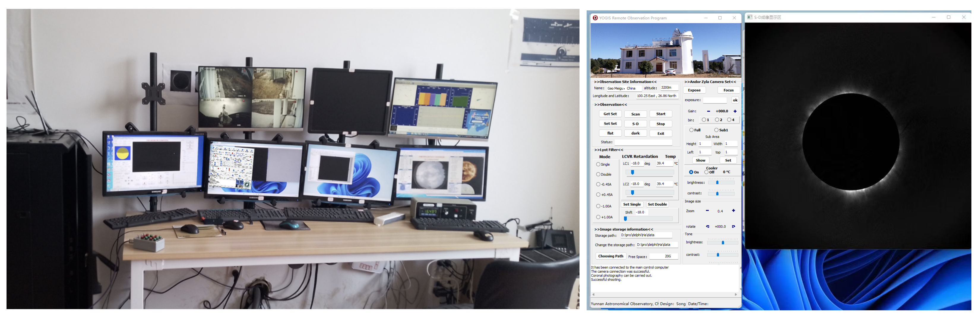
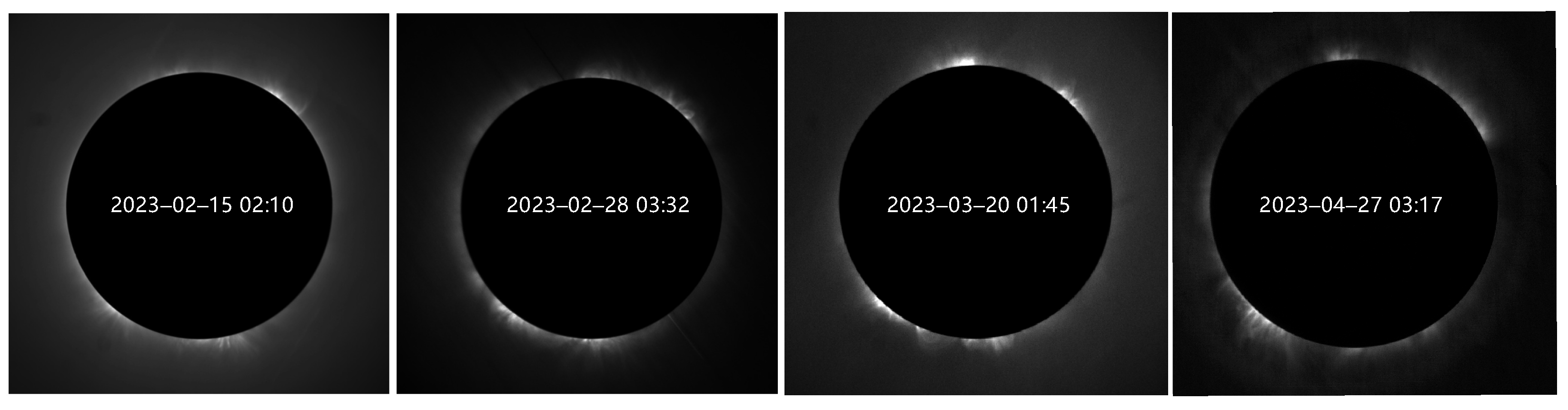
5. Practical Observations

The integrated observation system of YOGIS was substantially completed by the end of 2020. Since then, several enhancements have been made, primarily aimed at improving the processing of Level 1 and Level 2 coronal images and coronal velocity field data. YOGIS currently operates primarily in a local observational capacity. A dedicated observer is deployed on a rotational basis at the observatory to ensure continuous system oversight. The left panel of Figure 11 depicts a live feed from on-site operations, providing real-time visualization of the observational setup. To facilitate comprehensive system monitoring, a multi-display interface is implemented to concurrently visualize instrumental status and performance metrics. Figure 10 depicts the actual local observation interface of YOGIS. The left side of the image displays the main operating interface, with the top toolbar facilitating access to various subsystems. Clicking a button on the toolbar opens the corresponding subsystem control window (right side of Figure 10), displaying solar position information and telescope subsystem controls. Figure 12 presents the original coronal images captured in four wavebands, while Figure 13 displays the coronal images after the subtraction of the sky background. Complementing on-site operations, a rudimentary remote control interface (Figure 11, right panel) has been developed. This interface enables operators to execute observation sequences remotely under suitable conditions, affording operational flexibility while maintaining observational continuity.
Upon the completion of the observations, the processed data will be made available on the server’s website [18]. Figure 14 presents an overview of the observations conducted in the years 2022 and 2023 on the website. Coronagraphic observation data are accessible for direct download from the designated portal or via email request.

6. System Performance Metrics

(1) System Availability
Table 3 presents the availability metrics of the integrated observational system. First, the annual observable duration was computed using all-sky camera imagery. Subsequently, the cumulative exposure time of the primary camera—representing the system’s actual observational time—was derived from acquired coronagraphic image data. By cross-referencing these datasets with observation logs, the system’s availability rate and maintenance rate were determined. The system achieved an annual availability of 92% (based on 2021–2023 data), with a mean time between failures (MTBF) of 1100 h, significantly outperforming old manual systems (85% availability, MTBF 400 h).
(2) Observational Efficiency and Stability
Current operations require only one full-time technician for monthly log audits, compared to three full-time staff for round-the-clock monitoring in older systems. Automated scheduling enhanced the observation time utilization rate from 65% to 90%, enabling temporal resolution of coronagraphic observations as low as 10 s per dataset. Under optimal weather conditions, cumulative effective exposures reached 15,000 per day, accompanied by a 90% year-on-year reduction in manual interventions. Figure 15 illustrates the telescope’s stable tracking performance during a typical day, demonstrating an RMS stability of approximately 0.7 arcsecond without human intervention. This capability enables fully automated observations throughout the day, substantially reducing observational personnel’s operational workload compared to previous manual control methods.

7. Conclusions

The integrated observation system developed for the YOGIS coronagraph represents a highly specialized observational platform, tailored to support advanced solar corona studies. Leveraging the ASCOM platform, this system integrates key functionalities such as image acquisition, real-time data analysis, visualization, and multi-source data integration, thereby offering a robust and versatile toolset for researchers and operators. The software’s user interface is designed to be user-friendly, allowing even non-specialists to readily navigate the platform for basic image examination and data analysis. Following extensive operational deployment, the system has demonstrated reliable performance, stability, and a capacity for autonomous operation. These capabilities enhance the efficiency and automation of coronal observations. They significantly reduce the workload on observers and enable more frequent routine observations. Based on a decade of site surveys and the operation of the 10 cm coronagraph, we aim to develop larger aperture ground-based coronagraphs in the near future. Thus, the research presented here directly supports the urgent need for integrated observation systems for these future instruments.

Author Contributions

Conceptualization, T.S. and Y.L.; methodology, T.S., M.Z. and X.L.; data collection, X.Z., F.S., J.O., Q.L., X.W. and Q.L. (Qiang Liu); experiments, X.Z., F.S. and Q.L. (Qiwang Luo); writing—original draft preparation, T.S.; visualization, T.S.; writing—review and editing, Y.L. and J.O.; funding acquisition, Y.L. All authors have read and agreed to the published version of the manuscript.

Funding

This work was jointly supported by multiple funding sources. Specifically, it received partial support from the National Natural Science Foundation of China (NSFC 12473089, 12373063, U2031148, 11873092, 11973086, 12173086, 12163004, and 11873090). Additionally, financial assistance was provided by the Yunnan Fundamental Research Projects (202401AT070140) and the Fundamental Research Funds for the Central Universities (No.: 2682025CX031).

Data Availability Statement

Data are contained within the article.

Acknowledgments

We are grateful to the project of the Yunnan Key Laboratory of Solar Physics and Space Science under the number 202205AG070009. We thank the anonymous referees for helpful comments and suggestions on the manuscript.

Conflicts of Interest

The authors declare no conflicts of interest.

References

  1. Ichimoto, K.; Noguchi, M.; Tanaka, N.; Kumagai, K.; Shinoda, K.; Nishino, T.; Fukuda, T.; Sakurai, T.; Takeyama, N. A new imaging system of the corona at norikura. Publ. Astron. Soc. Jpn. 1999, 51, 383–391. [Google Scholar] [CrossRef]
  2. Liu, Y. The first coronagraph in China settled in Lijiang, Yunnan. Amat. Astron. 2014, 1, 60–63. [Google Scholar]
  3. Cui, C.; Li, J.; Cai, X.; Fan, Y.; Wang, F.; Cao, Z.; Su, L.; Fan, D.; Qiao, C.; He, B.; et al. Robotic Autonomous Observatory Network Review. Prog. Astron. 2013, 31, 141–159. [Google Scholar]
  4. Jian, W.; Ge, J.; Xiaoqi, Y.; Kun, H.; Feng, L.; Jian, R. The design of observatory control system of LAMOST. Plasma Sci. Technol. 2006, 8, 347. [Google Scholar] [CrossRef]
  5. Wang, Z.; Tian, Y.; Li, J.; Cao, Z.H.; Zhao, Y.H. A study on universal observation control system and its application for LAMOST. Res. Astron. Astrophys. 2021, 21, 149. [Google Scholar] [CrossRef]
  6. Liu, Y.; Zhang, X.; Song, T.; Sun, M.; Liu, D.; Wang, J.; Zhao, M.; Zhang, T.; Xu, F.; Fu, H.; et al. Ground experiment of a 50 mm balloon-borne coronagraph for near space project. In Proceedings of the 10th International Symposium on Advanced Optical Manufacturing and Testing Technologies: Large Mirror and Telescopes, Chengdu, China, 13 December 2021; SPIE: Bellingham, WA, USA, 2021; Volume 12070, pp. 94–100. [Google Scholar]
  7. Liu, Y.; Zhang, X. The coronal green line monitoring: A traditional but powerful tool for coronal physics. Proc. Int. Astron. Union 2018, 13, 169–170. [Google Scholar] [CrossRef]
  8. Gong, Q.; Socker, D. Theoretical study of the occulted solar coronagraph. In Proceedings of the Optical Systems Degradation, Contamination, and Stray Light: Effects, Measurements, and Control, Denver, CO, USA, 15 October 2004; SPIE: Bellingham, WA, USA, 2004; Volume 5526, pp. 208–219. [Google Scholar]
  9. Zhang, X.F.; Liu, Y.; Zhao, M.Y.; Liu, J.H.; Elmhamdi, A.; Song, T.F.; Li, Z.H.; Li, H.B.; Sha, F.Y.; Wang, J.X.; et al. Comparison of the Coronal Green-line Intensities with the EUV Measurements from SDO/AIA. Res. Astron. Astrophys. 2022, 22, 075012. [Google Scholar] [CrossRef]
  10. Zhang, X.F.; Liu, Y.; Zhao, M.Y.; Song, T.F.; Wang, J.X.; Li, X.B.; Li, Z.H. On the relation between coronal green line brightness and magnetic fields intensity. Res. Astron. Astrophys. 2022, 22, 075007. [Google Scholar] [CrossRef]
  11. Sha, F.; Liu, Y.; Zhang, X.; Song, T. Characterization and correction of the scattering background produced by dust on the objective lens of the Lijiang 10-cm coronagraph. Sol. Phys. 2023, 298, 139. [Google Scholar] [CrossRef]
  12. Xin, Y.X.; Bai, J.M.; Lun, B.L.; Fan, Y.F.; Wang, C.J.; Liu, X.W.; Yu, X.G.; Ye, K.; Song, T.F.; Chang, L.; et al. Astronomical site monitoring system at Lijiang observatory. Res. Astron. Astrophys. 2020, 20, 149. [Google Scholar] [CrossRef]
  13. Zhao, M.; Liu, Y.; Elmhamdi, A.; Kordi, A.; Zhang, X.; Song, T.; Tian, Z. Conditions for coronal observations at the Lijiang Observatory in 2011. Sol. Phys. 2018, 293, 1–13. [Google Scholar] [CrossRef]
  14. ASCOM—Standards for Astronomy [Web]. Available online: https://www.ascom-standards.org/ (accessed on 5 May 2025).
  15. Kozłowski, S.; Sybilski, P.; Konacki, M.; Pawłaszek, R.; Ratajczak, M.; Hełminiak, K.; Litwicki, M. Project Solaris, a Global Network of Autonomous Observatories: Design, Commissioning, and First Science Results. Publ. Astron. Soc. Pac. 2017, 129, 105001. [Google Scholar] [CrossRef]
  16. Wu, P.; Luo, C. ASCOM based research on the universal control protocol of telescope. In Proceedings of the 7th International Symposium on Advanced Optical Manufacturing and Testing Technologies: Design, Manufacturing, and Testing of Micro-and Nano-Optical Devices and Systems, Harbin, China, 21 August 2014; SPIE: Bellingham, WA, USA, 2014; Volume 9283, pp. 184–189. [Google Scholar]
  17. Ricci, D.; Cabona, L.; Tosi, S.; Zappatore, S. Toward the remotization and robotization of the OARPAF Telescope. In Proceedings of the Observatory Operations: Strategies, Processes, and Systems IX; SPIE: Bellingham, WA, USA, 2022; Volume 12186, pp. 189–195. [Google Scholar]
  18. Song, T.F. YNAO Coronagraph [Web]. Available online: http://sss.ynao.ac.cn/ (accessed on 5 May 2025).
Figure 1. Right: The temporary old building hosting the 10 cm coronagraph near Lijiang Station in 2013. Left: The current new building inside Lijiang Station with excellent logistics conditions.
Universe 11 00154 g001
Figure 2. Left: The first light taken on 25 October 2013. Right: The original compact and function-limited GUI for the 10 cm coronagraph.
Universe 11 00154 g002
Figure 3. Structural overview of YOGIS observation platform, control system, and telescope optical path.
Universe 11 00154 g003
Figure 4. Hardware composition of YOGIS system.
Universe 11 00154 g004
Figure 5. Schematic Diagram of YOGIS Low-level Architecture: Depicting Component Overview and Key Communication Channels.
Universe 11 00154 g005
Figure 6. Schematic Architecture of ASCOM Platform Development: Illustrating Network-Enabled ASCOM Alpaca for Cross-Platform Device Communication.
Universe 11 00154 g006
Figure 7. Proposed system architecture for YOGIS.
Universe 11 00154 g007
Figure 8. Software concept of YOGIS.
Universe 11 00154 g008
Figure 9. YOGIS high-level observing workflow. Stages in diagram are described in text.
Universe 11 00154 g009
Figure 10. Observation interfaces of YOGIS. (1) Main control interface. (2) Observation mode selection interface. (3) Camera and filter status display interface. (4) Log output interface for status display. (5) Solar position information interface. (6) Mount and dome status display and control interface. (7) Guiding status interface. (8) All-sky camera and meteorological parameter status interface.
Universe 11 00154 g010
Figure 11. Left: On-site live feed of YOGIS integrated observational system. Right: Remote control interface.
Universe 11 00154 g011
Figure 12. The coronal images in four wavebands photographed on 15 February 2023. (a) Single-band coronal image. (b) Double-band coronal image. (c) 0.45 Å band coronal image. (d) + 0.45 Å band coronal image.
Universe 11 00154 g012
Figure 13. Coronal images after the subtraction of the sky background. The images with high signal-to-noise ratios shown in the figure were obtained through observations on 15 February 2023, 28 February 2023, 15 March 2023, and 17 May 2023, respectively.
Universe 11 00154 g013
Figure 14. The interface for data preview on the YOGIS website.
Universe 11 00154 g014
Figure 15. Stability plot of the telescope tracking system on 18 November 2022. Top: Declination axis. Bottom: Right ascension axis.
Universe 11 00154 g015
Table 1. Parameters of three acquisition cameras in YOGIS.
ChannelCameraParametersField of View
5303 Å cameraDhyana 95 V2Pixel size: 11 μ m × 11 μ m
Resolution ratio: 2048 ( H ) × 2048 ( V )
Sensor type: BSI sCMOS
1.08 2.5 R
6328 Å cameraQHY 533Pixel size: 3.76 μ m × 3.76 μ m
Resolution ratio: 3008 ( H ) × 3028 ( V )
Sensor type: SONY IMX533C
2.5 R
Guide cameraASI-178Pixel size: 2.4 μ m × 2.4 μ m
Resolution ratio: 3096 ( H ) × 2080 ( V )
Sensor type: BSI sCMOS
2.0 R
Table 2. Critical state parameters and alert management procedures for YOGIS. The corresponding actions are categorized into three types: H (Hardware Failure), E (Cease Camera Exposure), and C (Cease Observations), where parenthetical labels A and M denote automatic resolution by the software system and manual intervention requirements, respectively.
ParameterDefinitionWarning ThresholdWarning LevelCorresponding Action
CCD_SCamera status≠0HighH/(M)
CCD_TCamera cooling temperature>−20 °CMediumE/(A)
Filter_SLCVR filter status 0 HighH/(M)
Filter_TFilter temperature control value<40 °CMediumE/(A)
P_dDeviation from the solar center>5 arcsecMediumE/(A)
Solar_ISolar intensity (used to determine if direct sunlight is present)<10 mwMediumE/(A)
I 1 Mount current>5 ALowE/(A)
P 1 Dome status≠1HighH/(M)
CloudinessCloud amount seen by all-sky camera>60%HighC/(M)
HumidityHumidity from weather station>70%HighC/(A)
Wind speedAverage wind speed from weather station>10 m/sHighC/(A)
F1Disk space<1 GBLowC/(A)
Table 3. Integrated observational system availability metrics.
YearAnnual Observable TimesActual Observational TimesMTBF
20211789.6 (h)1646.6 (h)1102
20221690.3 (h)1554.8 (h)1096
20231718.7 (h)1583.5 (h)1104
Disclaimer/Publisher’s Note: The statements, opinions and data contained in all publications are solely those of the individual author(s) and contributor(s) and not of MDPI and/or the editor(s). MDPI and/or the editor(s) disclaim responsibility for any injury to people or property resulting from any ideas, methods, instructions or products referred to in the content.

