Article

Predictive Torque Control Based on Discrete Space Vector Modulation of PMSM without Flux Error-Sign and Voltage-Vector Lookup Table

by
Ibrahim Mohd Alsofyani
and
Kyo-Beum Lee
*
Department of Electrical and Computer Engineering, Ajou University, World cup-ro 206, Yeongtong-gu, Suwon 16499, Korea
*
Author to whom correspondence should be addressed.
Electronics 2020, 9(9), 1542; https://doi.org/10.3390/electronics9091542
Submission received: 24 August 2020 / Revised: 14 September 2020 / Accepted: 19 September 2020 / Published: 21 September 2020
(This article belongs to the Special Issue High Power Electric Traction Systems)

Abstract

:
The conventional finite set–predictive torque control of permanent magnet synchronous motors (PMSMs) suffers from large flux and torque ripples, as well as high current harmonic distortions. Introducing the discrete space vector modulation (DSVM) into the predictive torque control (PTC-DSVM) can improve its steady-state performance; however, the control complexity is further increased owing to the large voltage–vector lookup table that increases the burden of memory. A simplified PTC-DSVM with 73 synthesized voltage vectors (VVs) is proposed herein, for further improving the steady-state performance of the PMSM drives with a significantly lower complexity and without requiring a VV lookup table. The proposed scheme for reducing the computation burden is designed to select an optimal zone of space vector diagram (SVD) in the utilized DSVM based on the torque demand. Hence, only 10 out of 73 admissible VVs will be initiated online upon the optimal SVD zone selection. Additionally, with the proposed algorithm, no flux error is required to control the flux demand. The proposed PTC-DSVM exhibits high performance features, such as low complexity with less memory utilization, reduced torque and flux ripples, and less redundant VVs in the prediction process. The simulation and experimental results for the 11 kW PMSM drive are presented to prove the effectiveness of the proposed control strategy.

1. Introduction

Permanent magnet synchronous motors (PMSMs) have garnered significant attentions in industrial applications [1,2]. They possess definite advantages over induction machines, such as higher efficiency, faster response, and excellent cooling features. A few control algorithms can be used to drive PMSMs for high-performance applications, such as direct torque control (DTC), which has the merits of simple configuration, fast torque dynamic, and less parameter sensitivity. In addition, no frame transformation is required. However, this control method comprises hysteresis comparators, which cause major drawbacks, i.e., variable switching frequencies, large torque ripples, and demanding sampling requirements [3,4,5].
Numerous studies have been conducted to solve these classical DTC drawbacks [6,7,8,9,10]. The variations of DTC include finite set-predictive torque control (FS-PTC), which has experienced substantial growth compared with other control algorithms owing to its interesting advantages, such as intuitive concept, fast dynamics, and easy realization [11,12,13,14]. In addition, constraints and nonlinearities can be included in FS-PTC, such as switching frequency and current protection. Furthermore, FS-PTC is a variation of direct torque control, which is known for its quick dynamic performance [6]. Nevertheless, a few inherent challenges are encountered when implementing FS-PTC [14]. Only a single switching state is applied for the entire sampling period, which results in a variable switching frequency, as well as an increase in flux and torque ripples compared with other modulator-based methods.
The large flux and torque ripples can be reduced by applying duty cycle control methods by inserting zero voltage to adjust the duty ratio of the optimal voltage vector (VV) [15,16,17]. However, the drawbacks of this method are that the calculation of the duty cycle is complicated and highly dependent on machine parameters. Another attractive solution is to use the discrete space-vector modulation (DSVM) for torque and flux ripple reduction. This method was first introduced in [18] and [19] for synthesizing a large number of virtual VVs within a single sampling interval to enhance the performance of the classical DTC technique. Nevertheless, a complicated lookup table was designed to select the optimal VV based on the requirement of torque, flux, and flux position. Additionally, this larger and more complex flux and torque hysteresis comparators were required. The concept of DSVM was introduced into FS-PTC through simulation [20,21]. Nevertheless, enumerating all the VVs increases the calculation load significantly, which renders it unsuitable for real applications. The calculation of a reference VV for deadbeat predictive torque control (DB-PTC) with the DSVM strategy has been introduced in [22,23]. Although, good performance is achieved in terms of flux and torque ripple reduction, this method requires a complex derivation for the reference VV, which is highly parameter dependent. Thus, the system can deteriorate owing to the parameter variations. The authors of [24] introduced an alternative PTC-DSVM based on the DTC strategy for 37 VVs. However, the complex lookup table for storing VVs resulted in a large burden of memory, and the flux and torque ripples were comparable to those of the conventional FS-PTC. Recently, PTC-DSVM with no suboptimality has been introduced [25]; however, this method requires a number of stages for enumerating VVs with various switching tables.
Herein, a simplified PTC-DSVM of PMSMs using online generated VVs with extending the degree of freedom to 73 VVs (i.e., real and virtual VVs) is proposed. The proposed strategy allows for a further increase in the estimation accuracy and reducing the flux and torque ripples in the steady-state performance. Nevertheless, the VV-based lookup tables utilized in previous methods to reduce computation time cannot be applied owing to the tedious implementation and the high complexity that increases the load of memory. Unlike the conventional method [25], the proposed PTC-DSVM introduces a simplified strategy to increase the system accuracy and reduce the computation time by designing an optimal zone of space vector diagram (SVD) for each flux position depending on torque demand, and hence, eliminating the need for the flux sign to control the flux demand. Moreover, large, and complex VV lookup tables are not required. The SVD of DSVM is subdivided into twelve zones with ten admissible VVs in each zone. After the SVD zone is determined, the candidate VVs will be initiated online to be sent to the cost function for selecting the best VV. For an easy implementation, the proposed method uses the space vector PWM to synthesize the optimal VV during the entire control period. The effectiveness of the proposed PTC-DSVM strategy is verified by simulation and experimental results.

2. Conventional FS-PTC of PMSM

2.1. PMSM Model

The dynamic model of the PMSM can be defined in terms of complex vectors, which are expressed in the stationary reference frame as follows:
v s = R s · i s + d ψ s d t
ψ s = L s · i s +   ψ p m
T e = 3 2 p · ( ψ s · i s ) ,
where v s   ( = [ v s α   v s β ] T ) is the stator voltage; i s   ( = [ i s d   i s q ] T ) is the stator current; R s is the stator resistance; ψ s ( = [ ψ s α   ψ s β ] T ) is the stator flux linkage; ψ p m ( = [ ψ r α   ψ r β ] T ) is the permanent magnet flux linkage; P is the number of pole pairs; Te is the electrical torque; Ls is the stator self-inductance.

2.2. Conventional FS-PTC

The first step in designing the FS-PTC is to discretize the continuous Equations (1)–(3). In the PTC of PMSMs, the discretized stator flux linkage, ψ s ( k ) , and electrical torque, T e , are estimated as follows:
ψ s ( k ) = L s · i s ( k ) + ψ p m ( k )
T e = 3 2 p · (   ψ s ( k ) · i s ( k ) )
The predicted stator flux linkage can be derived as:
ψ s ( k + 1 ) =   ψ s ( k ) + T s · v s ( k ) + T s R s · i s ( k ) + T s · Y · ω r ( k ) ,
and the predicted stator current is expressed as:
i s ( k + 1 ) = A · i s ( k ) + B · v s ( k ) + C ,
where
  • i s = [ i s α i s β ] , v s = [ v s α v s β ] , Y = [ ψ s β ψ s α ] ,
  • A = [ 1 R s · T s / L s L s · T s · ω r ( k ) L s . T s · ω r ( k ) 1 R s · T s / L s ]
  • B = [ T s / L s 0 0 T s / L s ] , C = [ 0 ψ p m · ω r · T s / L s ]
According to the predicted values of the stator flux and torque, the electromagnetic torque can be predicted as follows:
T e ( k + 1 ) = 3 2 p . (   ψ s ( k + 1 ) · i s ( k + 1 ) ) ,
where ω r is the rotor speed; k and k + 1 indicate the present and predicted sampling discrete steps, respectively.
A two-level voltage source inverter comprises eight VVs; six active VVs (v1v6) and two passive VVs (v0 and v7), as shown in the space vector diagram of Figure 1a. To determine the optimum VV among the possible VVs, v0v7, a cost function is configured as follows:
g = | T r e f   T e ( k + 1 ) | + Q ψ | ψ r e f |   ψ s ( k + 1 ) | | ,
where Q ψ is the weighting factor that determines the relative importance of the flux control objective. Q ψ is considered, in this paper, as the ratio of rated torque and flux ( T r a t e d / ψ r a t e d ).
T r e f and ψ r e f are the torque and flux linkage references at the kth sampling time, respectively. Therefore, the output stator voltage in terms of the switching states (Sa, Sb, and Sc) can be expressed as follows:
v s = 2 3 V D C ( S a + S b e 2 π / 3 + S c e 2 π / 3 )
where VDC is the direct current (DC) link voltage.

3. Proposed PTC-DSVM Strategy

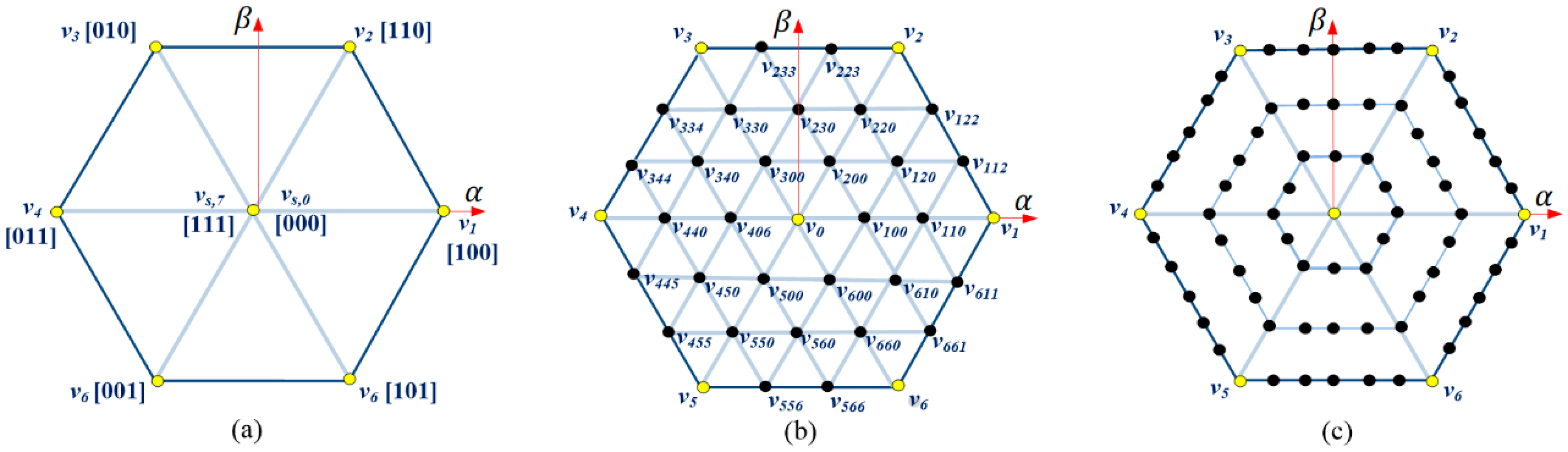
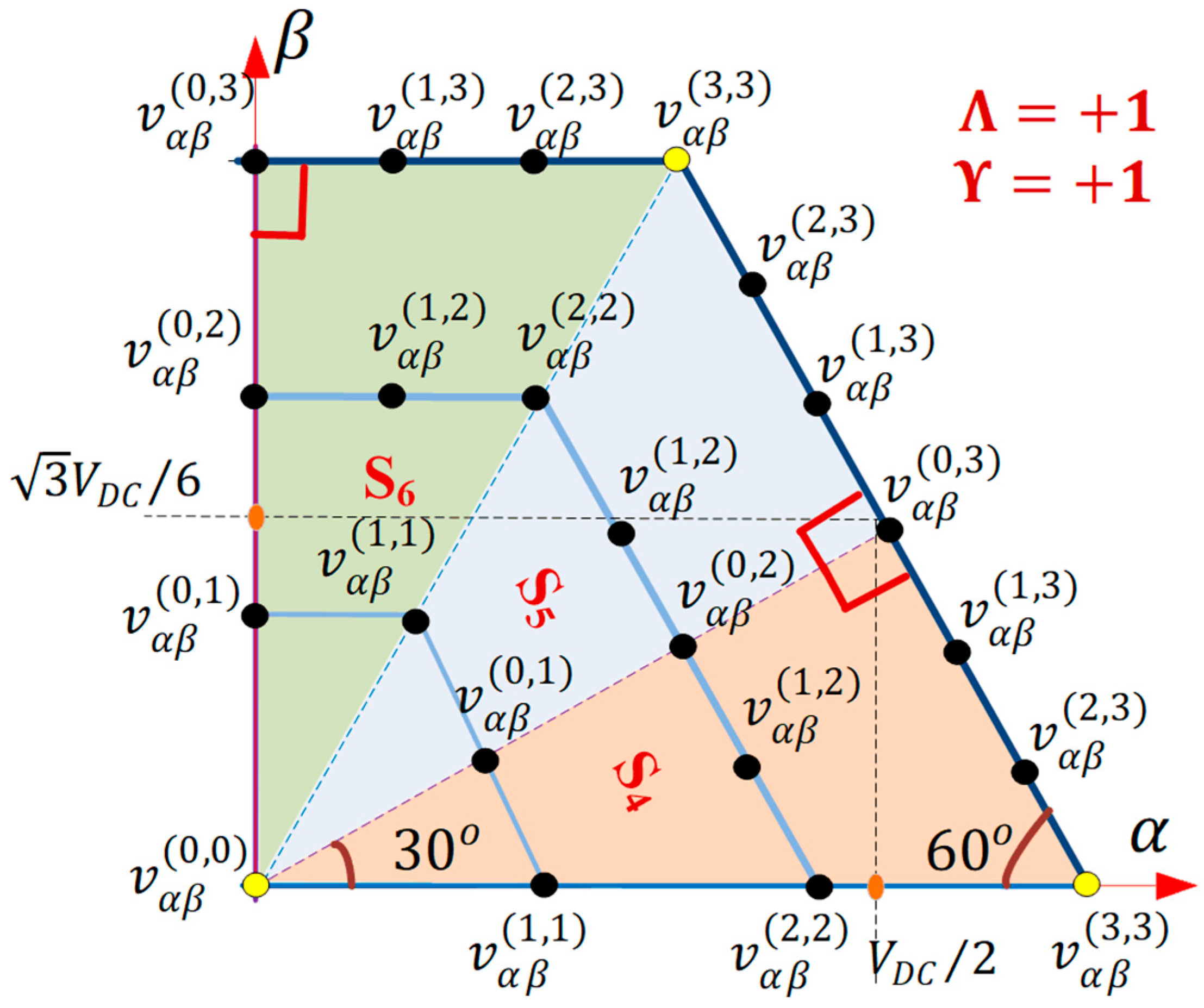
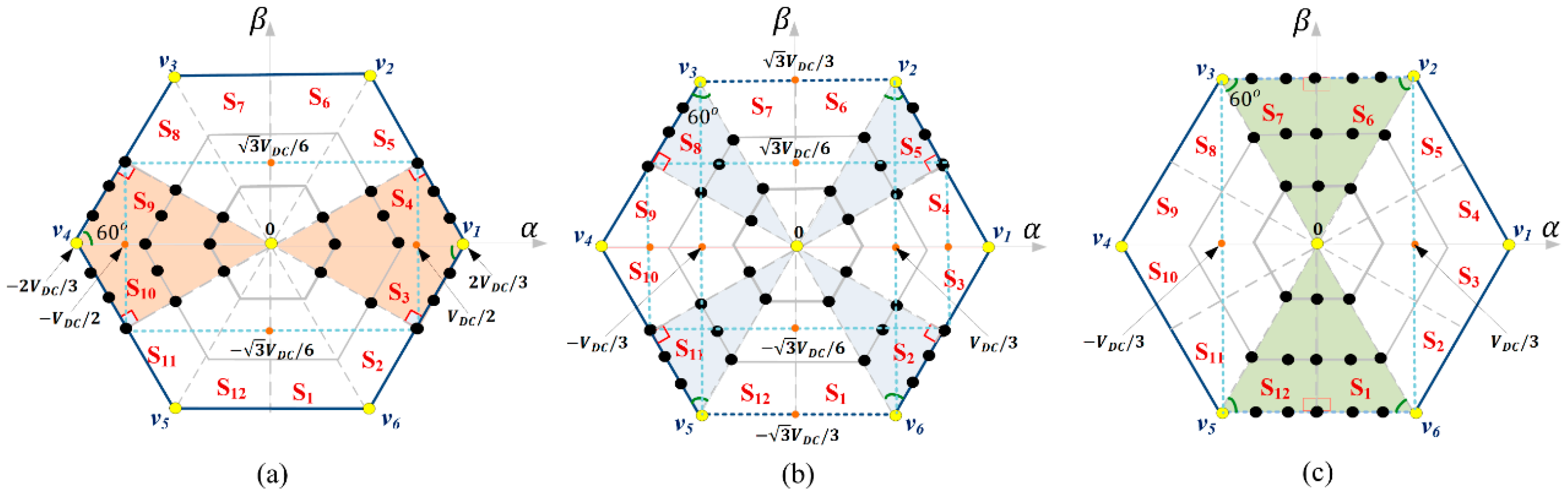
3.1. Synthesis of Virtual VVs

Despite the good features of the conventional FS-PTC method, large fluxes and torque ripples are still presented in the steady-state performance [12,13]. In addition, stator currents have large harmonic distortions. This is primarily caused by the limitations of the admissible switching states.
DSVM is an attractive solution for synthesizing virtual VVs ( v v i r ) in addition to real VVs ( v j ) in one sampling period. This can enlarge the voltage degree of freedom and hence address the abovementioned issues regarding the conventional FS-PTC of the PMSM drives. In the conventional PTC-DSVM, the production of v v i r is similar to that reported in [18,22,24,25], i.e., it is synthesized by subdividing T s into three segments, as follows:
v v i r = j = 1 , 2 , N t j · v j ,   { v j ( v 0 ,   v 1 , , v 7 ) } ,
where the total number of VVs (n) is given by:
n = 3 N 2 + 3 N + 1 ,
where N is the number of segments within a sampling time, and t j denotes the time interval for each segment. Figure 1b shows the SVD for this DSVM method when N is set to 3, where the total VV is 37. The yellow and black dots in the SVDs indicate the real and virtual VVs, respectively. An instance of the virtual VV is shown in Figure 1b, i.e., v 610 , which denotes the arrangement of real VVs v 6   ,   v 1 , and v 0 applied in one sampling time. In this DSVM method, index N cannot be greater than 3, because this will result in more voltage segments per sampling period, causing more complexity and larger lookup tables; hence, a large sampling time and heavy computation burden are required.
However, increasing the number of virtual VVs can improve the estimation accuracy and reduce the flux and torque ripples. Hence, an alternative DSVM strategy can be accomplished using the method outlined in [23], in which the SVD comprises concentric hexagonal diagrams (CHDs). Each CHD contains VVs of different sizes, and the number of VVs are expressed as follows:
n ( m ) = 12 · m ,   { [ m = 1 : η ]   n ( 0 ) = 1 } ,
where η is the number of CHDs. The number of virtual VVs in the SVD depends on its index η . Figure 1c depicts the proposed SVDs with synthesized real and virtual VVs when η is 3. The number of real and virtual VVs are calculated based on (13), which involve 73 VVs (i.e., 72 VVs and a zero-VV).
As mentioned previously, considering all real and virtual VVs significantly increases the computation burden in the prediction process, which results in an extremely long sampling time. In addition, it is difficult to implement all of these VVs in FS-PTC using a VV-based lookup table [24]. Therefore, a control method to reduce the calculation process of a digital signal processor (DSP) is required.
Hence, unlike the previous PTC-DSVM methods, the proposed strategy does not require storing VVs in lookup tables. In this study, the SVD was divided into twelve zones (i.e., S1S12). In each SVD zone, ten VVs (one real active VV, one real zero VV, and eight virtual VVs) were synthesized upon initialization. Notably, the group of proposed SVD zones share symmetrical characteristics based on the α β frame coordinate system, as illustrated in Figure 2. For instance, S3 is symmetrical with respect to S4, S8, and S10. Thus, the VVs in the SVD can be synthesized using only three mathematical expressions in the α β coordinate system for each symmetrical SVD zone, as follows:
S 3 ,   S 4 ,   S 8 , S 10   { v α ( x , y ) = Λ · V D C 6 η ( ( x + 3 y ) ) v β ( x , y ) = Υ · V D C 6 η ( 3 · ( x + y ) )
S 2 ,   S 5 ,   S 8 , S 11   { v α ( x , y ) = Λ · V D C 6 η ( ( x + 3 y ) ) v β ( x , y ) = Υ · V D C 6 η ( 3 · ( x + y ) )
S 1 ,   S 6 ,   S 7 , S 12   { v α ( x , y ) = Λ · V D C 3 η ( x ) v β ( x , y ) = Υ · V D C 3 η ( 3 · y ) ,
where x and y are the values in each coordinate of each voltage zone; VDC is the DC-link voltage of the inverter; Λ and Υ are the coefficient values depending on the SVD zones as tabulated in Table 1. Figure 3 shows the coordinate labels of α β VVs in SVD zones S4, S5, and S6 when the coefficient values of Λ and Υ are both +1. Notably, the same set of voltage labels at the (x,y) coordinate plane { v α β ( 0 , 0 ) , v α β ( 0 , 1 ) ,   v α β ( 1 , 1 ) ,   v α β ( 0 , 2 ) ,   v α β ( 1 , 2 ) , v α β ( 2 , 2 ) ,   v α β ( 0 , 3 ) ,   v α β ( 1 , 3 ) , v α β ( 2 , 3 ) , and v α β ( 3 , 3 ) } were applied upon initiation. Nevertheless, the value for each voltage label depended on the corresponding equations as well, i.e., (14) to (16).

3.2. Predicted Online-Generated VVs

The conventional PTC-DSVM scheme (in Figure 1b) [24] is based on the DTC strategy, which depends on the flux position and the increase and decrease for both the flux and torque. In this method, the SVD was subdivided into four regions. This means a quarter of SVD is utilized for each prediction process. Accordingly, the α β frame was divided into six sectors to identify the direction of the flux rotation. For each sector, a quarter of SVD, 12 out of 37 VVs, were selected based on the flux and torque demands. Figure 4a shows an illustrated example for the prediction process of the conventional PTC-DSVM. Hence, 48 VVs must be transformed and then stored in the α β voltage components for only a single sector. This results in a complex and large lookup table that increases the burden of memory. Additionally, most of the admissible VVs are redundant and far from the circular flux trajectory, as shown in Figure 4a.
Nevertheless, the proposed PTC-DSVM can reduce this complexity and increase the number of predicted VVs, as it only stores (14), (15), and (16) and the coefficient values for the SVD zones in Table 1 without having to store the VVs. Notably, the VVs are only initiated when one of the equations, i.e., (14) to (16) in the α β form is invoked, followed by the selection of coefficient values in Table 1. The proposed method determines the optimal SVD zone using the stator flux position ( ϕ s ) and torque error ( T e r r = T r e f T e ; for an increasing torque, ( T e r r 0 ) ( ) and decreasing torque ( T e r r > 0 ) ( ) ) without requiring the flux sign. The position of the stator flux, ϕ s , is estimated as:
ϕ s = arctan ( ψ β / ψ α )
Since the SVD zones change periodically by an angle, π / 6 rad, with respect to the initialized equation (i.e., (14) to (16)), the α β plane of the flux rotation is also divided into twelve sectors ( ϕ s ( 1 ) ϕ s ( 12 ) ), as shown in Figure 4b. In this way, the selection of the optimal SVD zone will be limited depending on the nearest VVs to the circular flux trajectory, thus reducing the computational burden of the control process. This feature allows for an additional benefit of eliminating the need for the flux sign as mentioned previously. The VVs in the optimal SVD zone can satisfy the increase and decrease in the stator flux because the VVs in the selected SVD zone are very tangential and adjacent to the circular flux path, resulting in smaller torque and flux ripples. In addition, the number of redundant VVs in the prediction process will be reduced. The optimum SVD zone for each flux position sector is determined offline depending on the increase or decrease in the torque, as shown in Table 2. This can be explained and analyzed using the space vector illustration of the stator flux linkage, which is positioned in the middle of ϕ s ( 3 ) , as shown in Figure 4b. When the stator flux linkage, ψ s , moves in a counterclockwise direction, the optimum SVD zone is S7, in which the VVs { v α β ( 0 , 0 ) , v α β ( 0 , 1 ) , v α β ( 1 , 1 ) , v α β ( 0 , 2 ) , v α β ( 1 , 2 ) , v α β ( 2 , 2 ) , v α β ( 0 , 3 ) , v α β ( 1 , 3 ) , v α β ( 2 , 3 ) , and v α β ( 3 , 3 ) } are initiated by (16) and then the coefficient values are obtained; Λ = –1 and Υ = +1. At this flux position, all the generated VVs except for the zero-VV, v α β ( 0 , 0 ) , can increase the torque; simultaneously, the flux can be regulated to follow the circular flux path using the same active VVs. It is noteworthy that v α β ( 0 , 0 ) denotes the real zero-VV, v 0 or v 7 , whereas v α β ( 3 , 3 ) indicates the real active VV, v 3 . However, if the torque decreases ( T e r r > 0 ), which means that the stator flux linkage, ψ s , moves in a clockwise direction, the optimum SVD zone is S1. From Table 2, S1, which is symmetrical to S7, was applied to generate the corresponding VVs using (16) but with different coefficient values: Λ = + 1 and Υ = 1 . Similarly, the generated VVs can satisfy the torque decrease and flux regulation within the circular flux path. It is noteworthy that the same zero-VV, v α β ( 0 , 0 ) was generated, nevertheless the active VV, v α β ( 3 , 3 ) , in this SVD zone was v 6 .
Consequently, only 10 VVs were considered instead of 73 VVs during the calculation and prediction. Notably, only VVs in the selected SVD zone will be generated. Hence, the candidate VVs were restricted, which significantly reduced the computation burden on the DSP.

3.3. Delay Compensation and Cost Function Minimization

To compensate for the delay, the VV at time k + 2 for predicting the motor variables (i.e., i s ( k + 2 ) , ψ s ( k + 2 ) ,   and   T e ( k + 2 )   ) should be calculated in the cost function instead of k + 1. To determine the optimum VV among the 10 generated VVs in the selected SVD zone, a cost function must be configured based on (18):
g = | T r e f   T e ( k + 2 ) | + Q ψ   | ψ r e f |   ψ s ( k + 2 ) | |
Finally, after the optimum VV, vopt, in the α β form was obtained based on the selected SVD zone, it was sent to a space-vector PWM in the next sampling time to obtain the three-phase duties easily.

3.4. Overall Control Procedure of the Proposed PTC-DSVM

The overall control procedure can be summarized by the following sequence:
  • Estimate the stator flux, ψ s ( k ) , and torque, T e ( k ) .
  • Predict the stator current, i s ( k + 1 ) , stator flux, ψ s ( k + 1 )   , and torque,   T e ( k + 1 ) by applying the optimal VV, v ( k ) .
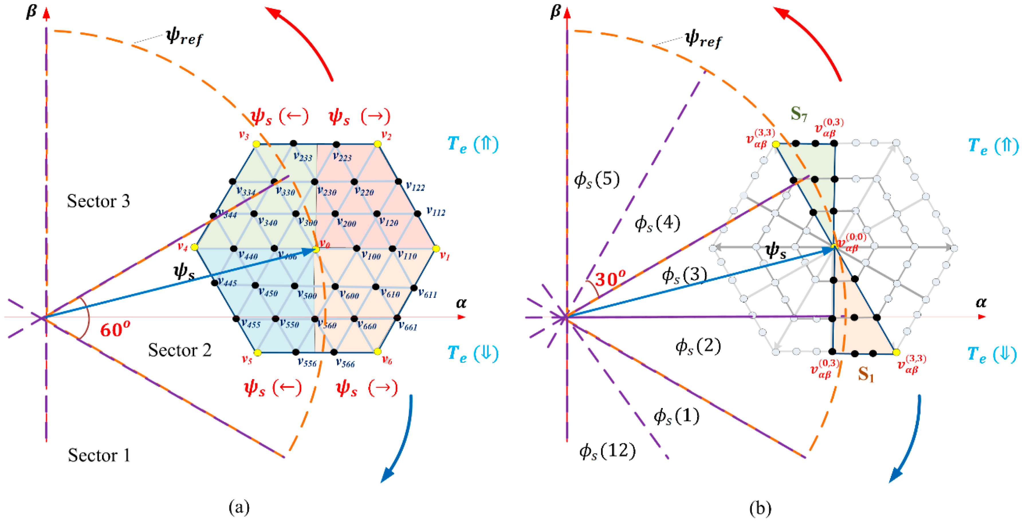
  • Obtain the optimal SVD zone based on the torque requirement at the specified flux position according to Table 2.
  • Generate the α β voltages in the selected SVD zone with respect to the corresponding equations (i.e., (14) to (16)), and then select coefficients Λ and Υ in Table 1.
  • Predict the stator flux, ψ s ( k + 2 ) , stator current, i s ( k + 2 ) ,   and   torque , T e ( k + 2 ) , for each reduced α β VV in the SVD zone.
  • Select the optimal VV, vopt, that minimizes the cost function (18), and apply it at the next sampling time using a space vector PWM.
Figure 5 shows the block diagram of the proposed PTC-DSVM strategy.

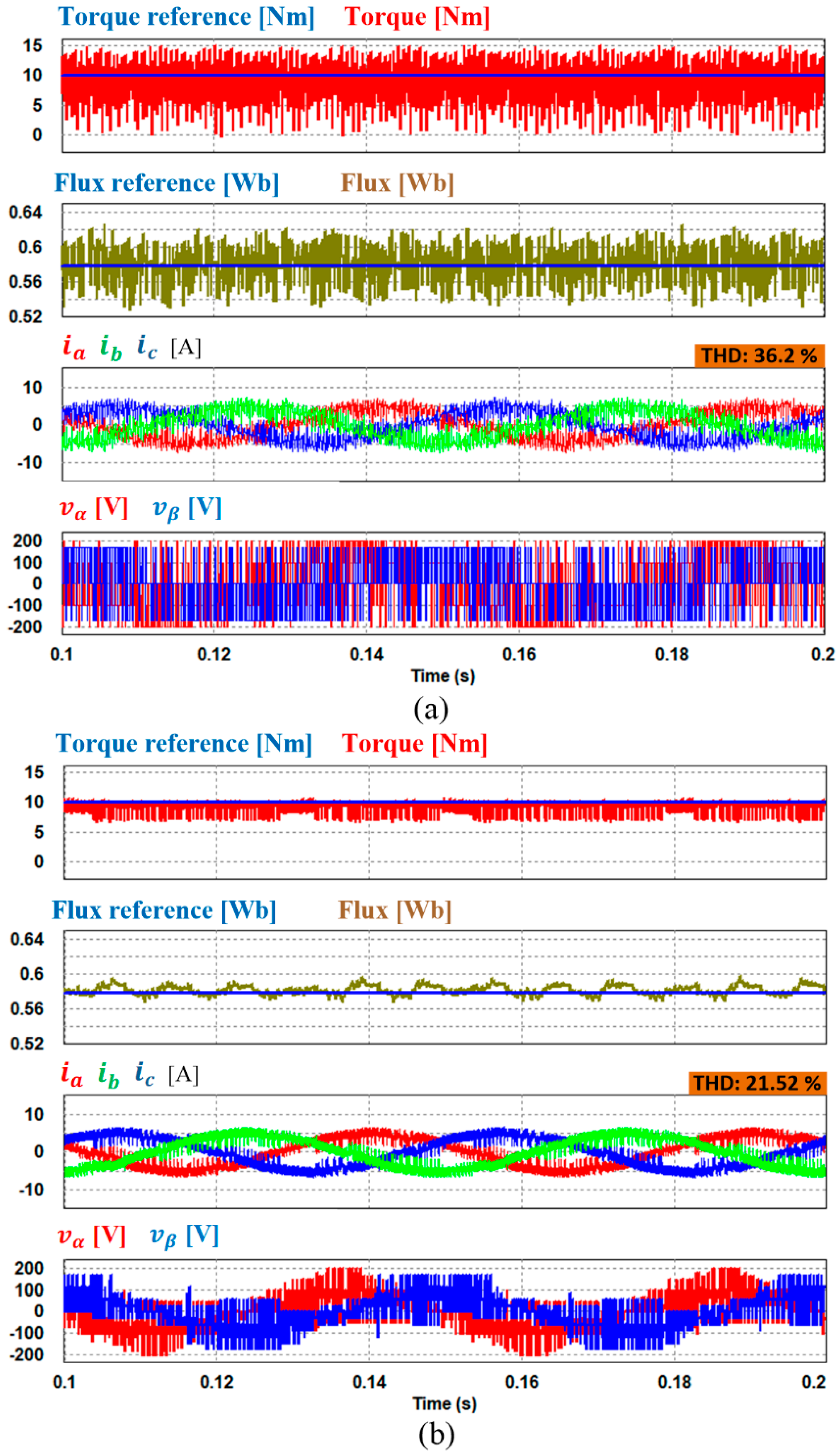
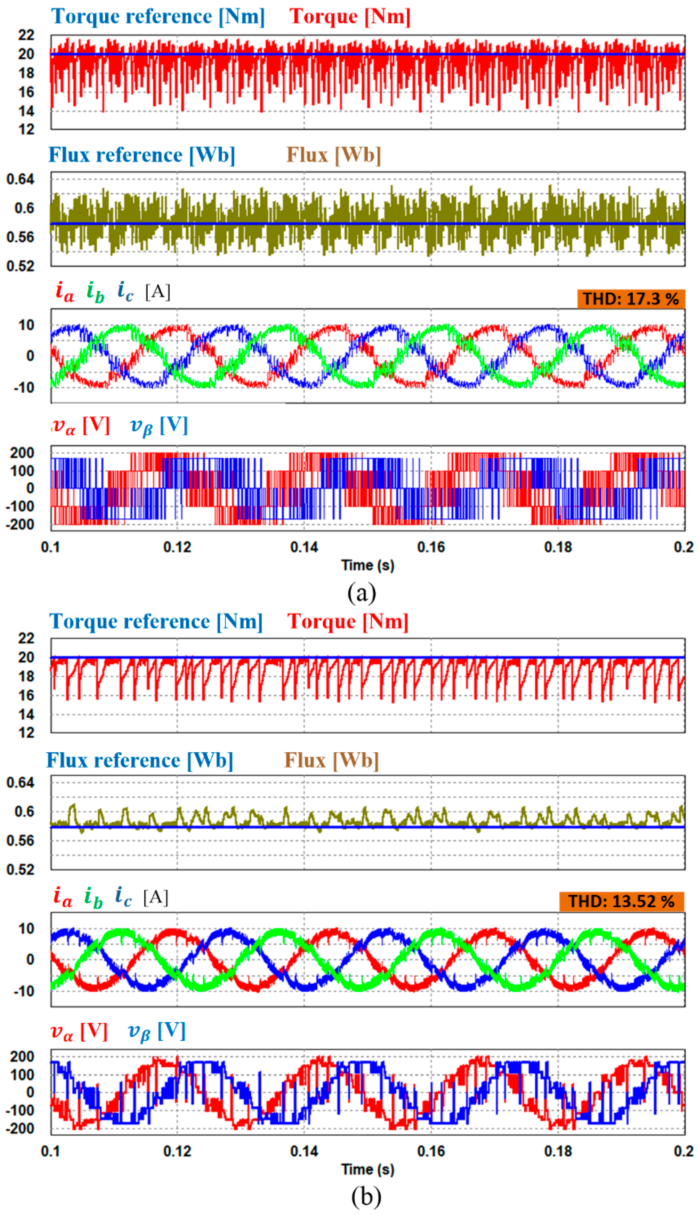
4. Simulation Results

The proposed PTC-DSVM (i.e., 73 VVs) of PMSM was simulated using a PSIM simulation tool. To investigate the performance of the proposed PTC-DSVM, a comparison has been carried out with the conventional FS-PTC which adopts eight switching states. The specifications of the machine parameters are provided in Table 3. The flux reference ψ r e f is set at 0.58 Wb. For the aim of fair comparison, the weighting factor is the same for all the compared methods. The applied DC-link voltage is 300 V in line with the experiment.
Figure 6 shows the simulation results in a steady state operation at 800 rpm with 20 Nm for the conventional FS-PTC and proposed PTC-DSVM, respectively. It is clearly observed that the proposed PTC-DSVM has reduced greatly the torque and flux ripples in comparison to the conventional method. Additionally, it is obvious in the proposed method (Figure 6b) that the α β voltages are more sinusoidal owing to the increase of virtual VVs. In addition, the total harmonic distortion (THD) level in the proposed method is better than that in the classical FS-PTC method. The performance of the proposed and conventional techniques was also evaluated at 400 rpm under 10 Nm of load torque as shown in Figure 7. It can be observed that the torque and flux ripples of the proposed PTC-DSVM is significantly reduced compared with the conventional method. Moreover, the THD level is greatly reduced from 36.2% in the conventional method to 21.52% in the proposed PTC-DSVM scheme.

5. Experimental Results
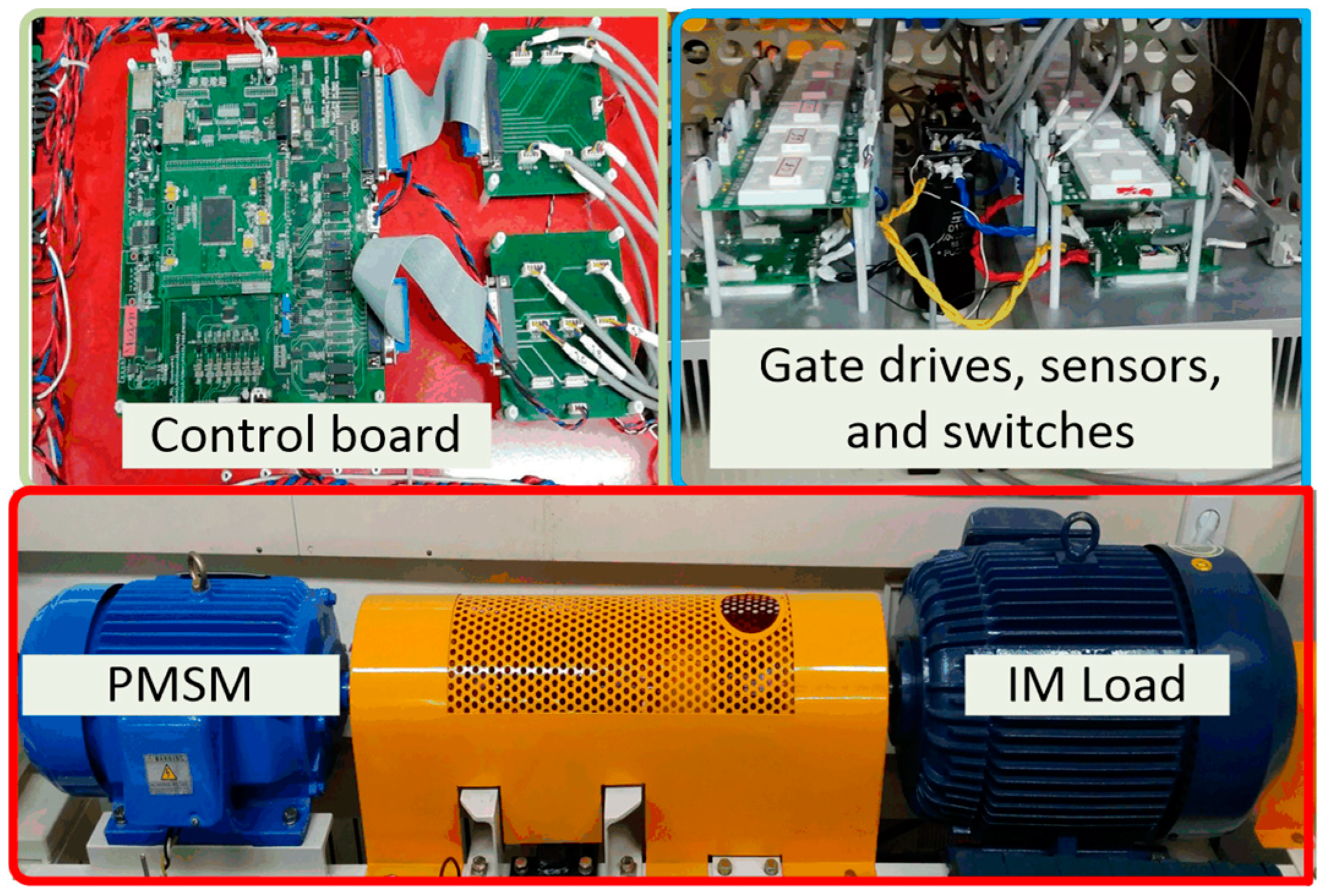
5.1. Implementation

Figure 8 shows the test bench to investigate the feasibility of the proposed PTC-DSVM for PMSMs. It comprised a DSP 28335 control platform and three-phase intelligent power module equipped with IGBTs. To load the machine, an induction motor controlled by a commercial YASUKAWA inverter was applied. The PMSM specifications and parameters are provided in Table 3.
The classical FS-PTC and proposed PTC-DSVM methods were performed on the same experimental test bench for comparison under the same sampling time of 100 μs. The weighing factor, between the torque and flux for both methods was experimentally tuned to 150. Unlike the FS-PTC, the optimal VVs in the proposed PTC-DSVM underwent space vector PWM to reconstruct the three-phase duties before they were sent to the output terminals.

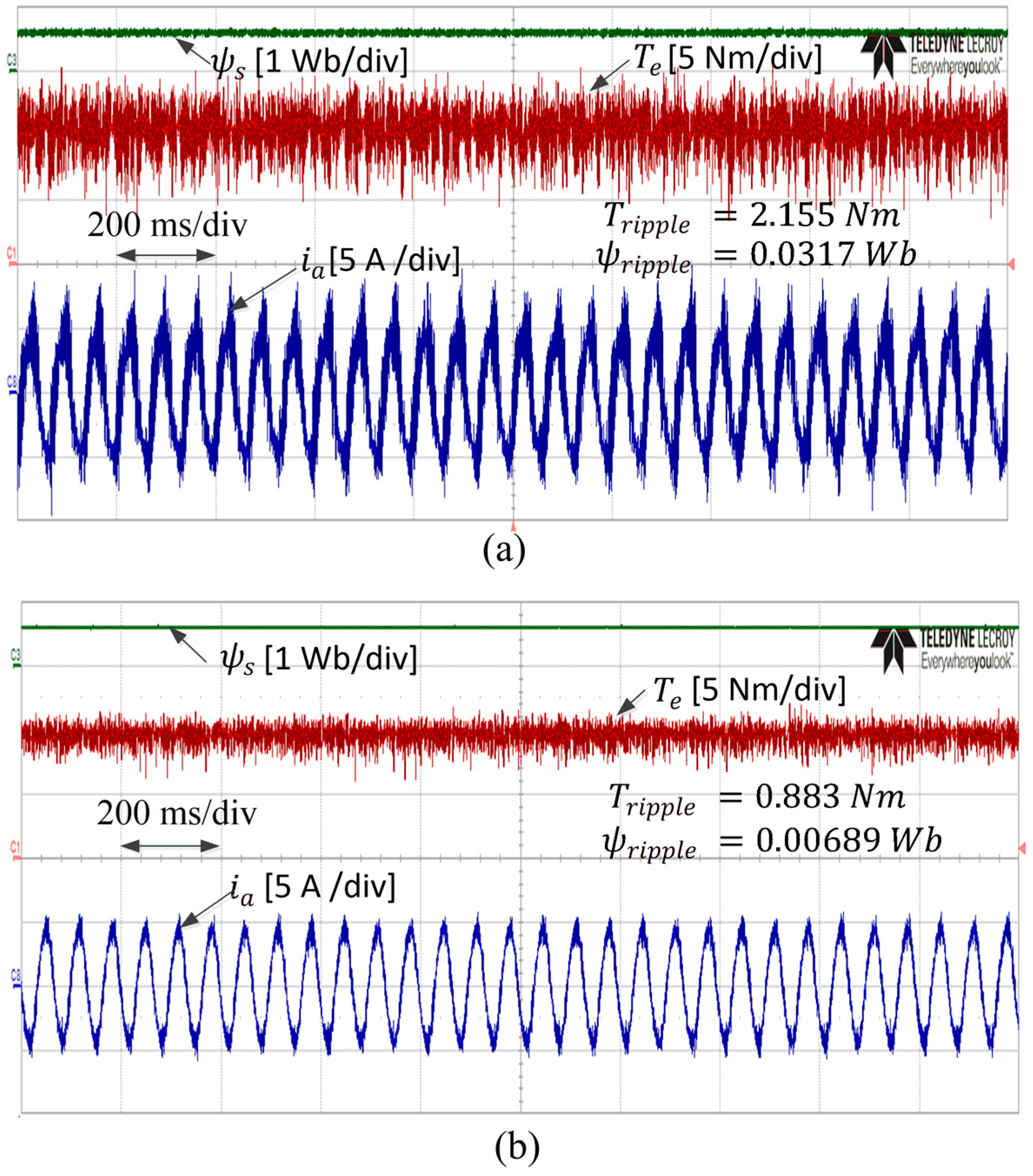
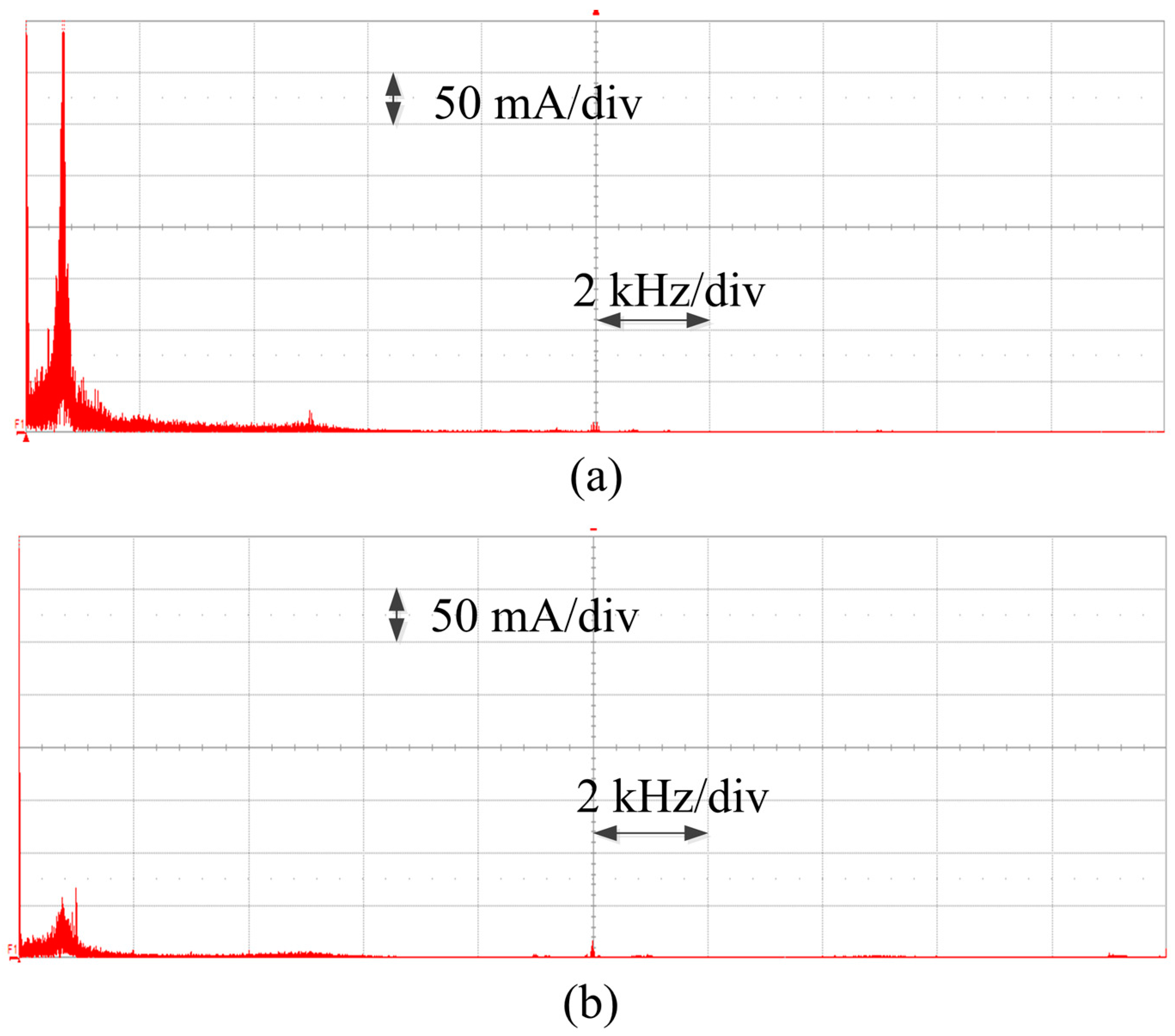
5.2. Steady-State Operation

Figure 9 shows the steady-state operation of the FS-PTC, which adopted eight admissible real VVs and the proposed PTC-DSVM at a speed of 300 rpm with 10.0 Nm. The torque ripple ( T r i p p l e ) and flux ripple ( ψ r i p p l e ) for all control methods were performed online at the steady-state operation according to [26]. The torque ripples obtained were 2.155 Nm for FS-PTC and 0.883 Nm for the proposed PTC-DSVM. Meanwhile, the flux ripples of the FS-PTC and the proposed PTC-DSVM were 0.0317 and 0.00689 Wb, respectively. Thus, it is evident that the proposed PTC-DSVM exhibited the smaller torque and flux ripples compared with the conventional method.
Figure 10 shows the frequency spectra of the corresponding A-phase motor current (ia) of the FS-PTC and proposed PTC-DSVM methods, for the speed and torque conditions shown in Figure 9. Notably the frequency spectrum of the PMSM current in FS-PTC exhibited the large harmonics, which were intensively distributed below 2 kHz compared with the proposed PTC-DSVM method. Nevertheless, the proposed PTC-DSVM-2 exhibited lower harmonics owing to the effective selection of admissible VVs.

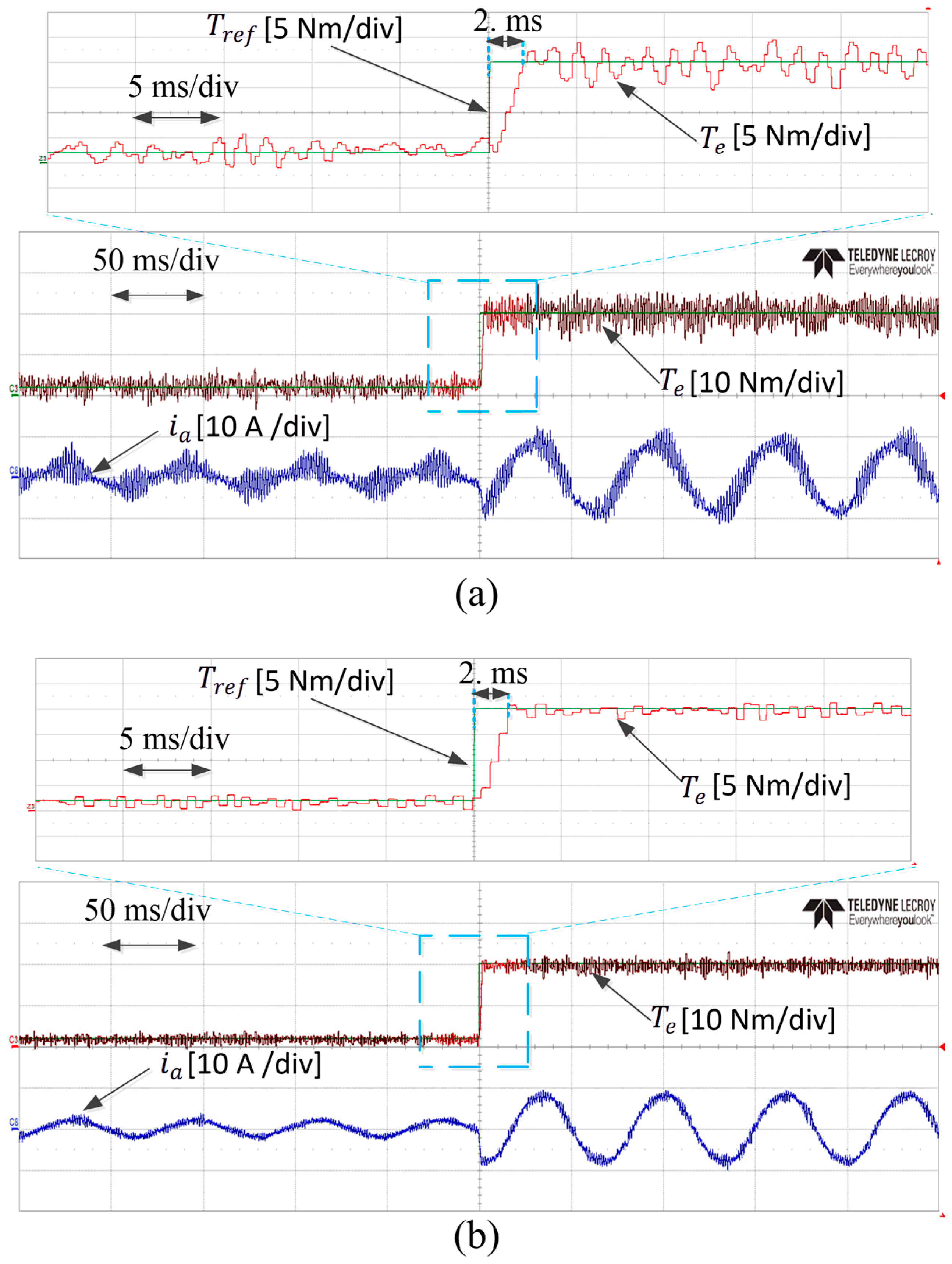
5.3. Transient Torque Operation

Figure 11a,b shows the dynamic torque performances for the FS-PTC and the proposed PTC-DSVM, respectively. A step change in the torque from 2 to 20 Nm was applied during a speed operation of 300 rpm. Notably, both methods demonstrated fast and comparable torque dynamic performances. However, the classical FS-PTC method underwent significantly larger torques and current ripples compared with the proposed PTC-DSVM algorithm. Furthermore, it was observed that the torque ripple in the FS-PTC was larger at 20 Nm compared with that at 2 Nm. Nevertheless, the proposed PTC-DSVM maintained approximately the same torque ripple in both torque references.

6. Conclusions

In this study, a PTC-DSVM with online generated VVs for the high performance of PMSM drives was proposed. Compared with the previous PTC-DSVM methods (i.e., with 37 VVs), the proposed method has a lower complexity, as no VV lookup table was required. The proposed PTC-DSVM strategy exhibited other advantageous features: Reduced number of redundant VVs in the prediction process, further reduction in the torque and flux ripples owing to the increased VVs, and lower current harmonic distortions. Additionally, compared with the other DB-PTC methods requiring complex calculation processes of the reference VV, the proposed PTC-DSVM method can be implemented easily and it has been designed to employ a larger number of virtual VVs to obtain higher degrees of freedom in the PMSM drives. The predicted VVs were activated in every voltage zone according to the torque demand at every flux position. The experimental results were provided to verify the effectiveness of the proposed PTC-DSVM strategy.

Author Contributions

Conceptualization and writing—original draft, methodology and validation, formal analysis, I.M.A.; resources, review, and editing, K.-B.L. All authors have read and agreed to the published version of the manuscript.

Funding

This research was supported in part by the Korea Electric Power Corporation, under grant R19XO01-20 and in part by “Human Resources Program in Energy Technology” of the Korea Institute of Energy Technology Evaluation and Planning (KETEP), granted financial resource from the Ministry of Trade, Industry and Energy, Republic of Korea, under grant 20194030202370.

Conflicts of Interest

The authors declare no conflict of interest.

References

  1. Choi, Y.S.; Choi, H.H.; Jung, J.W. Feedback linearization direct torque control with reduced torque and flux ripples for IPMSM drives. IEEE Trans. Power Electron. 2016, 31, 3728–3737. [Google Scholar] [CrossRef]
  2. Mwasilu, F.; Jung, J.W. Enhanced fault-tolerant control of interior PMSMs based on an adaptive EKF for EV traction application. IEEE Trans. Power Electron 2016, 31, 5746–5758. [Google Scholar] [CrossRef]
  3. Alsofyani, I.M.; Kim, K.Y.; Lee, S.S.; Lee, K.B. A Modified Flux Regulation Method to Minimize Switching Frequency and Improve DTC-Hysteresis-Based Induction Machines in Low-Speed Regions. IEEE J. Emerg. Sel. Top. Power Electron. 2019, 7, 2346–2355. [Google Scholar] [CrossRef]
  4. Hakami, S.S.; Mohd Alsofyani, I.; Lee, K.-B. Low-Speed Performance Improvement of Direct Torque Control for Induction Motor Drives Fed by Three-Level NPC Inverter. Electronics 2020, 9, 77. [Google Scholar] [CrossRef] [Green Version]
  5. Alsofyani, I.M.; Bak, Y.; Lee, K.B. Fast Torque Control and Minimized Sector-Flux Droop for Constant Frequency Torque Controller Based DTC of Induction Machines. IEEE Trans. Power Electron. 2019, 34, 12141–12153. [Google Scholar] [CrossRef]
  6. Habibullah, M.; Lu, D.D.; Xiao, D.; Osman, I.; Rahman, M.F. Selected Prediction Vectors Based FS-PTC for 3L-NPC Inverter Fed Motor Drives. IEEE Trans. Ind. Appl. 2017, 53, 3588–3597. [Google Scholar] [CrossRef]
  7. Adase, L.A.; Alsofyani, I.M.; Lee, K. Predictive Torque Control With Simple Duty-Ratio Regulator of PMSM for Minimizing Torque and Flux Ripples. IEEE Access 2020, 8, 2373–2381. [Google Scholar] [CrossRef]
  8. Zhou, Y.; Chen, G. Predictive DTC strategy with fault-tolerant function for six-phase and three-phase PMSM series-connected drive system. IEEE Trans. Ind. Electron. 2018, 65, 9101–9112. [Google Scholar] [CrossRef]
  9. Alsofyani, I.M.; Lee, K. Improved Transient-Based Overmodulation Method for Increased Torque Capability of Direct Torque Control With Constant Torque-Switching Regulator of Induction Machines. IEEE Trans. Power Electron. 2020, 35, 3928–3938. [Google Scholar] [CrossRef]
  10. Alsofyani, I.M.; Lee, K.B. Finite-Set Predictive Torque Control Based on Sub-divided Voltage Vectors of PMSM with Deadbeat Control and Discrete Space Vector Modulation. In Proceedings of the 2019 IEEE Applied Power Electronics Conference and Exposition (APEC), Anaheim, CA, USA, 17–21 March 2019; IEEE: Piscataway, NJ, USA, 2019; pp. 1853–1857. [Google Scholar]
  11. Zhang, Y.; Zhang, Y.; Wang, X.; Zhu, W. Adaptive Digital Predictive Peak Current Control Algorithm for Buck Converters. J. Power Electron. 2019, 19, 613–624. [Google Scholar]
  12. Zhang, X.; Hou, B. Double vectors model predictive torque control without weighting factor based on voltage tracking error. IEEE Trans. Ind. Electron. 2018, 33, 2368–2380. [Google Scholar] [CrossRef]
  13. Li, C.; Wang, G.; Li, F.; Li, H.; Xia, Z.; Liu, Z. Fault-Tolerant Control for 5L-HNPC Inverter-Fed Induction Motor Drives with Finite Control Set Model Predictive Control Based on Hierarchical Optimization. J. Power Electron. 2019, 19, 989–999. [Google Scholar]
  14. Vazquez, S.; Rodriguez, J.; Rivera, M.; Franquelo, L.G.; Norambuena, M. Model predictive control for power converters and drives: Advances and trends. IEEE Trans. Ind. Electron. 2017, 64, 935–947. [Google Scholar] [CrossRef] [Green Version]
  15. Zhang, Y.; Yang, H. Model Predictive Torque Control of Induction Motor Drives with Optimal Duty Cycle Control. IEEE Trans. Power Electron. 2014, 29, 6593–6603. [Google Scholar] [CrossRef]
  16. Yan, L.; Dou, M.; Hua, Z.; Zhang, H.; Yang, J. Optimal Duty Cycle Model Predictive Current Control of High-Altitude Ventilator Induction Motor with Extended Minimum Stator Current Operation. IEEE Trans. Power Electron. 2018, 33, 7240–7251. [Google Scholar] [CrossRef]
  17. Zhao, B.; Li, H.; Mao, J. Double-Objective Finite Control Set Model-Free Predictive Control with DSVM for PMSM Drives. J. Power Electron. 2019, 19, 168–178. [Google Scholar]
  18. Casadei, D.; Serra, G.; Tani, A. Implementation of a direct control algorithm for induction motors based on discrete space vector modulation. IEEE Trans. Power Electron. 2000, 15, 769–777. [Google Scholar] [CrossRef]
  19. Wei, X.; Chen, D.; Zhao, C. Minimization of torque ripple of direct torque controlled induction machines by improved discrete space vector modulation. Elect. Power Syst. Res. 2004, 72, 103–112. [Google Scholar] [CrossRef]
  20. Vazquez, S.; Leon, J.I.; Franquelo, L.G.; Carrasco, J.M.; Martinez, O.; Rodriguez, J.; Cortes, P.; Kouro, S. Model predictive control with constant switching frequency using a discrete space vector modulation with virtual state vectors. In Proceedings of the 2009 IEEE International Conference on Industrial Technology, Gippsland, VIC, Australia, 10–13 February 2009; IEEE: Piscataway, NJ, USA, 2009; pp. 1–6. [Google Scholar]
  21. Villegas, J.; Vazquez, S.; Carrasco, J.M.; Gil, I. Model predictive control of a switched reluctance machine using discrete space vector modulation. In Proceedings of the 2010 IEEE International Symposium on Industrial Electronics, Bari, Italy, 4–7 July 2010; IEEE: Piscataway, NJ, USA, 2010; pp. 3139–3144. [Google Scholar]
  22. Wang, Y.; Wang, X.; Xie, W.; Wang, F.; Dou, M.; Kennel, R.M.; Lorenz, R.D.; Gerling, D. Deadbeat Model-Predictive Torque Control with Discrete Space-Vector Modulation for PMSM Drives. IEEE Trans. Ind. Electron. 2017, 64, 3537–3547. [Google Scholar] [CrossRef]
  23. Moon, H.; Lee, J.; Lee, K. A Robust Deadbeat Finite Set Model Predictive Current Control Based on Discrete Space Vector Modulation for a Grid-Connected Voltage Source Inverter. IEEE Trans. Energy Convers. 2018, 33, 1719–1728. [Google Scholar] [CrossRef]
  24. Amiri, M.; Milimonfared, J.; Khaburi, D.A. Predictive Torque Control Implementation for Induction Motors Based on Discrete Space Vector Modulation. IEEE Trans. Ind. Electron. 2018, 65, 6881–6889. [Google Scholar] [CrossRef]
  25. Osman, I.; Xiao, D.; Alam, K.S.; Akter, M.P.; Shakib, S.M.S.I.; Rahman, M.F. Discrete Space Vector Modulation Based Model Predictive Torque Control with No Sub-Optimization. IEEE Trans. Ind. Electron. 2020, 67, 8164–8174. [Google Scholar] [CrossRef]
  26. Ren, Y.; Zhu, Z.Q.; Liu, J. Direct Torque Control of Permanent-Magnet Synchronous Machine Drives with a Simple Duty Ratio Regulator. IEEE Trans. Ind. Electron. 2014, 61, 5249–5258. [Google Scholar] [CrossRef]
Figure 1. Space voltage vector (VV) diagram with (a) real VVs, (b) synthesized VVs using (11), and (c) synthesized VVs using (13).
Electronics 09 01542 g001
Figure 2. Symmetrical zones of the space vector diagram (SVD) depending on the coefficient values in Table 1 for (a) (14), (b) (15), and (c) (16).
Electronics 09 01542 g002
Figure 3. Coordinate values of the VVs in S4, S5, and S6 used in the proposed discrete space vector modulation (DSVM) into the predictive torque control (PTC-DSVM).
Electronics 09 01542 g003
Figure 4. Illustration for the VVs selection for a single flux sector of (a) conventional PTC-DSVM [24] and (b) proposed PTC-DSVM.
Electronics 09 01542 g004
Figure 5. Proposed control block diagram for PTC-DSVM of the permanent magnet synchronous motor (PMSM).
Electronics 09 01542 g005
Figure 6. Simulation results for the steady-state response of the PMSM at 800 rpm, 20 Nm. (a) Conventional finite set-predictive torque control (FS-PTC); (b) proposed PTC-DSVM.
Electronics 09 01542 g006
Figure 7. Simulation results for the steady-state response of the PMSM at 400 rpm, 10 Nm. (a) Conventional FS-PTC; (b) proposed PTC-DSVM.
Electronics 09 01542 g007
Figure 8. Experimental setup.
Electronics 09 01542 g008
Figure 9. Experimental steady-state response of the PMSM at 300 rpm, 10 Nm. (a) Conventional FS-PTC; (b) proposed PTC-DSVM.
Electronics 09 01542 g009
Figure 10. Experimental results of the frequency spectra of the A-phase motor current. (a) Conventional FS-PTC; (b) proposed PTC-DSVM.
Electronics 09 01542 g010
Figure 11. Experimental results of the torque step response from 2 to 20 Nm. (a) Conventional FS-PTC; (b) proposed PTC-DSVM.
Electronics 09 01542 g011
Table 1. Coefficient values depending on SVD zones.
SVD Zones
Coefficient ValuesS1S3S4S6S7S9S10S12
Λ +1+1–1–1
Υ –1+1+1–1
Table 2. Optimum space vector diagram zone for each flux sector.
ϕ ( 1 ) ϕ ( 2 ) ϕ ( 3 ) ϕ ( 4 ) ϕ ( 5 ) ϕ ( 6 ) ϕ ( 7 ) ϕ ( 8 ) ϕ ( 9 ) ϕ ( 10 ) ϕ ( 11 ) ϕ ( 12 )
T e r r 0 S5S6S7S8S9S10S11S12S1S2S3S4
T e r r > 0 S11S12S1S2S3S4S5S6S7S8S9S10
Table 3. PMSM parameters.
ParameterValue
Rated power11 [kW]
Rated current19.9 [A]
Rated speed1750 [r/min]
Rated torque60 [Nm]
Number of poles6
Stator resistance0.349 [Ω]
Stator inductance15.6 [mH]
Permanent magnet flux0.554 [Wb]

