1. Introduction
There are more than 600 million people in the world who suffer from disabilities and 80% of them are living in developing countries [
1]. In Indonesia, more than 30% of the total disabilities are caused by amputated limbs [
2]. The number of upper-limb amputees is less than that of lower-limb amputees with a 1:30 ratio. Even with the lesser case of the upper-limb amputees, the total number of sufferers is large in the world. Some of them have lost their lower arm limb, and are called transradial amputees [
3]. The sufferers certainly need a tool to replace their lost limbs to support their daily activities, called a prosthetic hand. In its development, the prosthetic socket design is made as comfortable as possible for the user. The manufacturing process has experienced rapid development during this decade from conventional to modern fabrication by applying the 3D printing method [
4]. The conventional method usually using the casting method is still widely used in prosthetic socket production in Indonesia. This method is likely to consume 2–3 days, is costly, and still needs direct contact from a highly skilled maker.
3D printing is an additive manufacturing method that has rapidly developed in the last decade [
5,
6]. In the medical field, the utilization of 3D printing is also experiencing a significant influence regarding its precision, customizability, and time and cost efficiency [
7]. A lot of studies regarding the production of prosthetic devices or prototypes using 3D printing are starting to emerge because it is convenient, customizable, and inexpensive [
8,
9,
10]. The use of 3D Computer-Aided Design (3D CAD) software is beneficial to the automated prosthetic production, especially on socket fabrication because of its effectiveness on the editing and digitalizing process of the products [
11].
A photogrammetry technique is a method which is able to convert 2D visual data into a 3D model in the form of a point-cloud coordinate. Retrieval of the data can employ optical sensors, such as cameras, lasers, and others [
12,
13]. In its application, the photogrammetry method is widely used for aerial mapping for geographical purposes, called long-range photogrammetry [
14,
15]. Besides long-range photogrammetry, the use of close-range photogrammetry is starting to emerge for historical, industrial, and medical applications [
13,
16,
17,
18,
19]. This method has already been analyzed by previous researchers who found that the method is effective and applicable to scan the 3D models accurately [
8,
20,
21]. By applying close-range photogrammetry, a digital camera is used for acquiring photos of all sides of the object thoroughly. The photos are then imported to the stitching software to create the 3D model. The output of this process, which is still a point-cloud coordinate, is converted to OBJ or STL. The model can be improved in 3D modeling or CAD software before entering the manufacturing process with 3D print.
In this study, a new method of transradial prosthetic socket fabrication is conducted using photogrammetry and 3D printing method. The method is aimed as an alternative method for manufacturing the prosthetic socket for our previous 3D printed myoelectric hands [
22,
23]. The photogrammetry technique incorporating a 3D printer is utilized to reduce the cost and manufacturing time for a transradial prosthetic socket. This method is already tested for manufacturing the below-knee or transtibial prosthetic socket. Based on the previous study, it can be concluded that this method can be applied for socket manufacturing [
8]. Validation was carried out to find that this idea could replace the conventional prosthetic socket production by comparing for both final products qualitatively utilizing the image processing method and usability test from the socket made by conventional casting and 3D printing methods.
2. Materials and Methods
In this study, a respondent/study participant was interviewed to obtain his biodata. He was male; 51 years old. This study proposes two-socket production methods: the new photogrammetry and 3D printing, and the conventional casting method. The analysis was carried out using usability and segment area conformities. The schematic diagram of this study is summarized in
Figure 1 below.
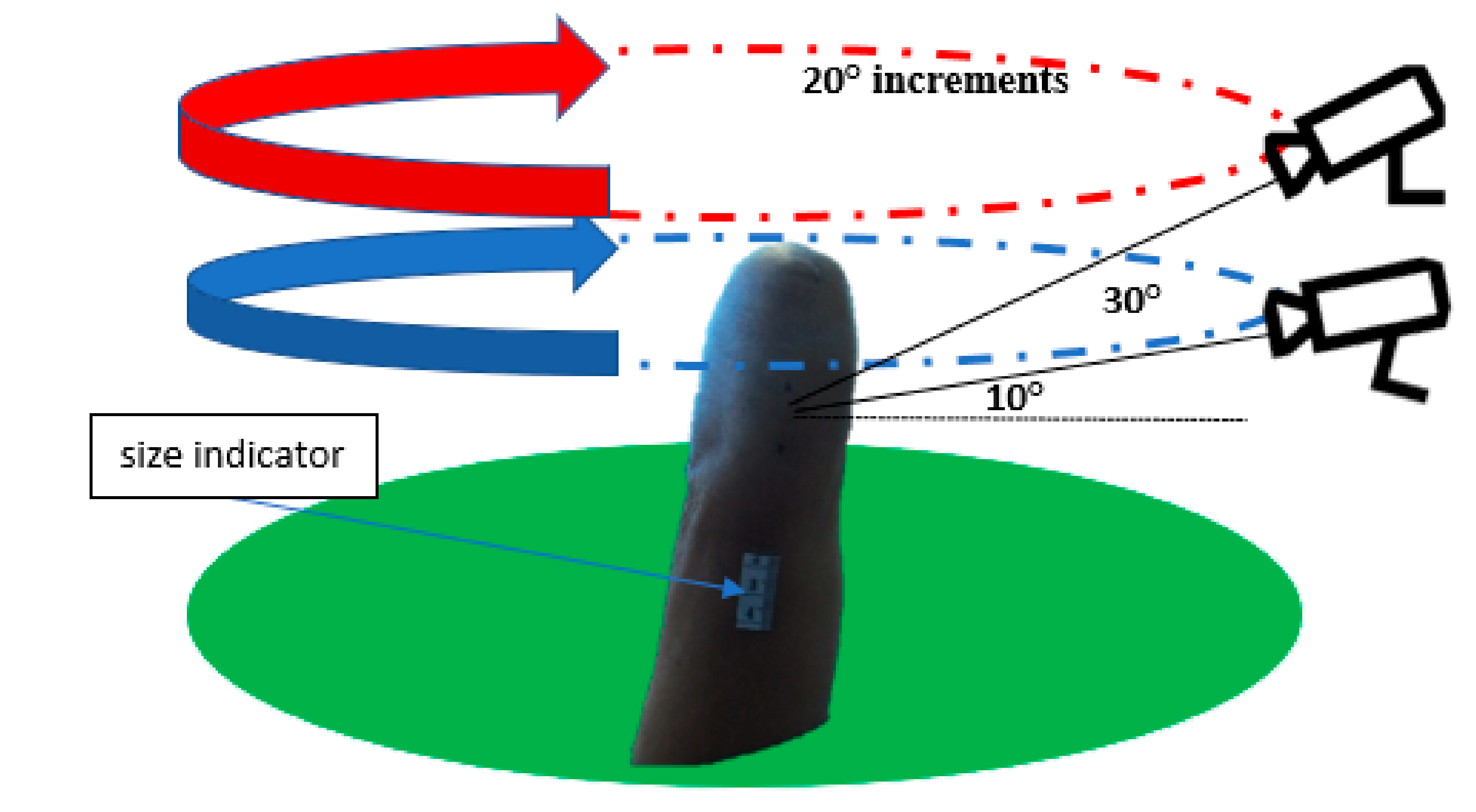
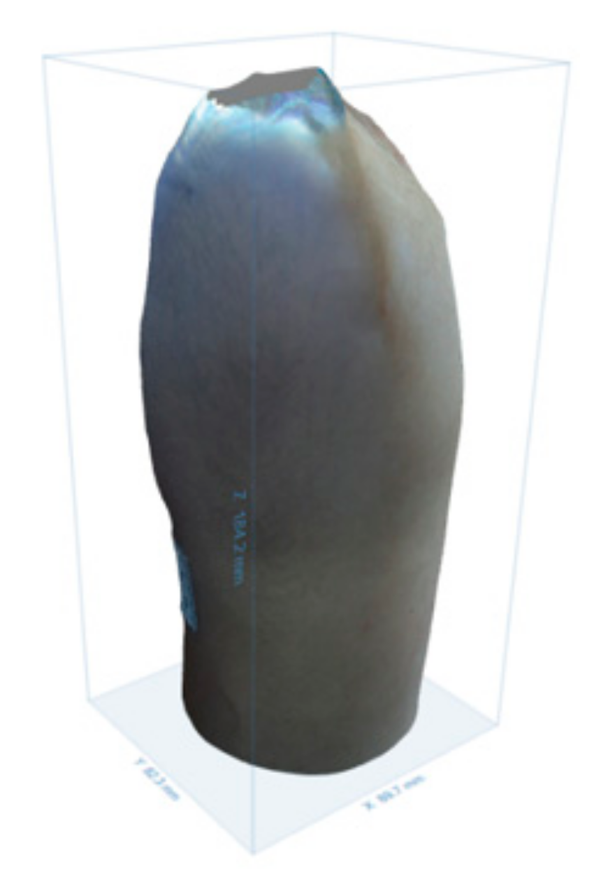
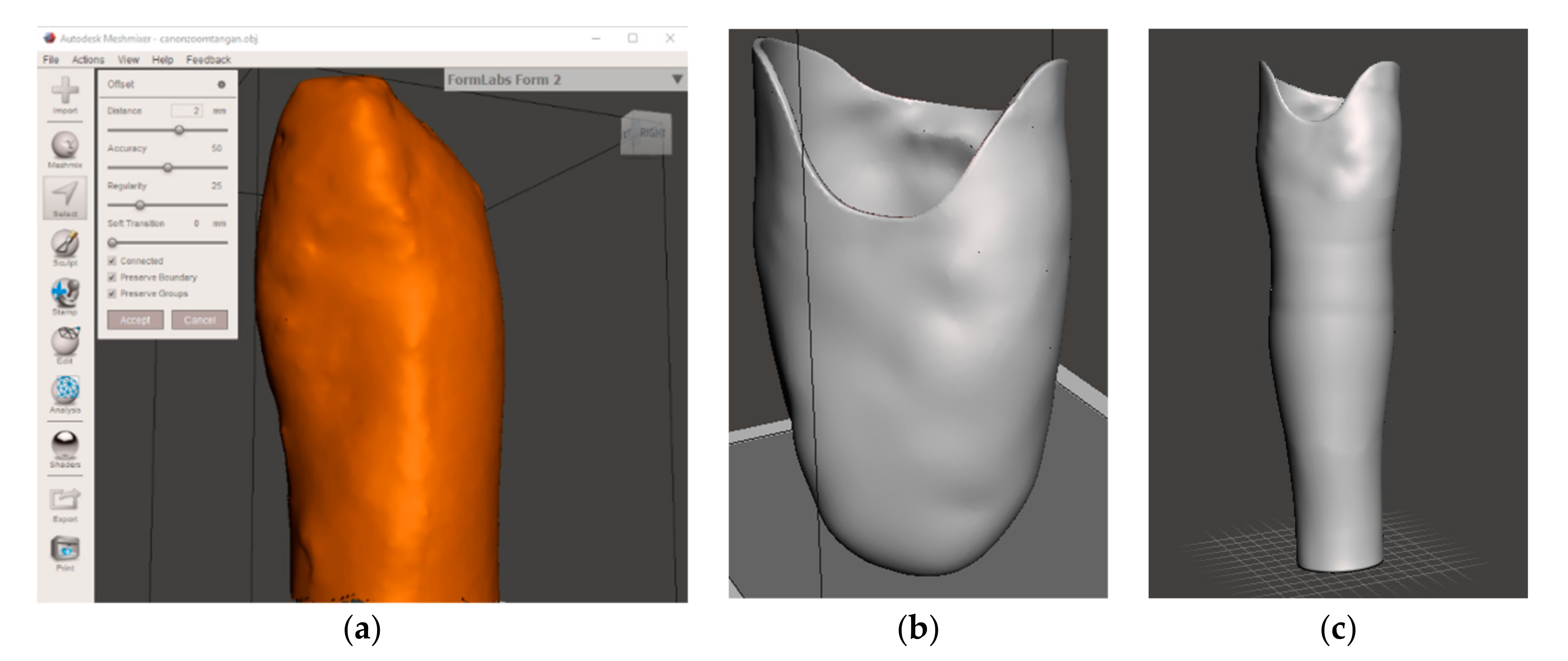
2.1. Photogrammetry Socket Fabrication Method
The photo retrieval for photogrammetry technique employed a Canon Powershot SX420IS (Canon Inc., Wuhan, China) camera wherein the previous study has already discussed the camera that can produce the best accuracy on photogrammetry. The specifications of this camera are 20 megapixels, 4.3–180.6 mm focal length, f/3.5 aperture range, 125–1600 ISO range, and has the optical zoom. This camera has the total average error for length, area, and volume in photogrammetry as low as 1.62% [
8]. The respondent′s stump images are taken using auto mode at 10° and 30° shooting angle with 20° increments, resulting in 36 images from all sides of the stump. The size indicator sticker is placed on the stump for the scaling process. The illustration of the image retrieval can be seen in
Figure 2 below.
The images then followed by a photogrammetry process to obtain a 3D model of this process using Autodesk Recap Photo 2018 Student Version. The software can create a 3D model from aerial and close-ranged photos from 20 images and is limited up to 100 images for each project. First, it obtains the raw object data that contain all objects captured by the camera, including the environment. The unnecessary parts in the model are cut and the model is scaled to obtain only the real size for the 3D model of the stump. The 3D model of the hand stump can be seen in
Figure 3.
The 3D model of the stump then processed using the Autodesk Meshmixer software to form a socket that fits the remaining limb and performs rectification. In this process, the 3D model of the stump is imported into the Autodesk Meshmixer software as shown in
Figure 4a. Then the socket is adjusted according to the condition of the hand stump by sculpting the desired part and making an offset socket thickness of 2.5 mm. The results are presented in
Figure 4b,c.
The final model of the socket is printed using a circular 3D printer (Karya3D, Semarang, Indonesia) with Polylactic acid (PLA) filament (Rajawali3D, Magelang, Indonesia). The slicing software used in this process is Repetier Host with a 0.4 mm nozzle, 0.2 mm layer height, 100% infill, 60 mm/s print speed, 210 °C nozzle temperature without heat bed. After that, the inner and outer side of the socket was polished with 400 and 1000 grid sandpaper.
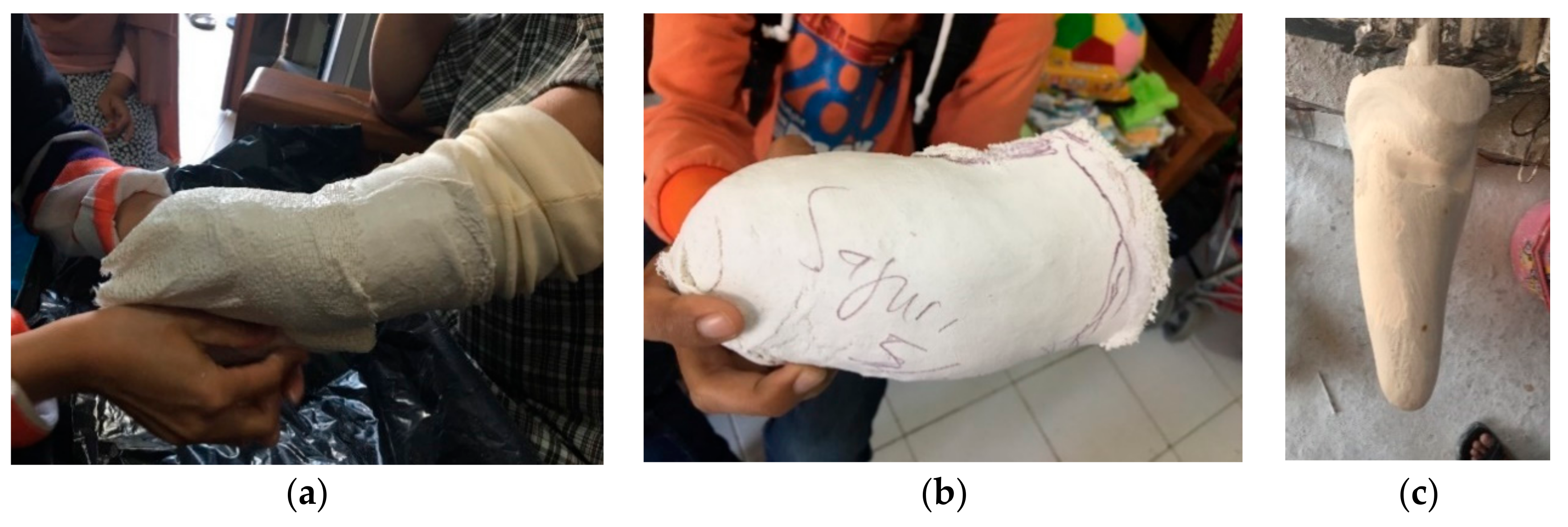
2.2. Casting Socket Fabrication Method
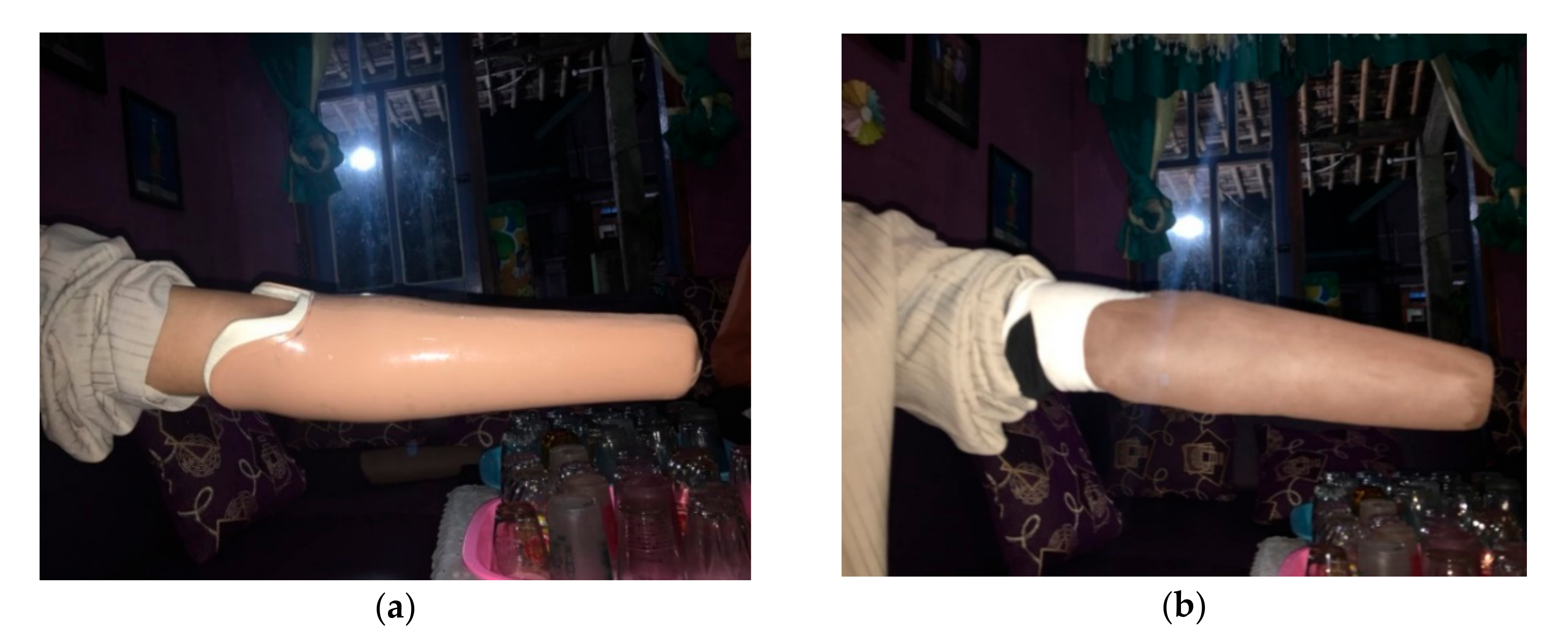
The casting method conducted, starting from the fitting of the respondent limb to identify the circumference, anatomical landmark, scarring, and sensitive areas. The thin casting stocking was then applied to the stump and was followed by making a negative mold using a plaster wrap and applying certain pressure to either side of the radius and ulna. The plaster wrap started to cure after a few minutes and was then removed from the stump. The next step was making a positive mold of the stump by casting the negative mold with powder gip. After the positive mold was created, the next step was reducing and adding an area to the positive gip, which is called the rectification stage.
Figure 5 shows the process of making a negative mold and rectification.
The following process after manufacturing the positive mold was measuring length, the largest and the smallest circumference of the positive plaster that was coated with a sponge. Two sheets of PVC plastic were cut according to their size. Two sides of the plastic were connected by ironing it until it was cooked. Some amount of thinner was poured into the first PVC until it became soft. The positive mold was coated with fiber on all sides. The mold was tied using a thread then re-coating the positive gip with 2 layers of stockinet. The thinner was poured again into the second PVC plastic to stick the PVC plastic over the stockinet until the positive bottom of the gip was already bound tightly. In the manufacturing of transradial prosthesis socket, the 500 mL of resin and 2 mL of catalyst were mixed in a stirring glass. After the resin and catalyst were well mixed, it was poured gradually into the positive gip through the funnel and spread all over the surface of the positive mold and vacuumed. After the resin and catalyst were dried, it was ready for the demolition of the positive mold to acquire the hard socket. Before the positive demolition of the gip was carried out, the trimline pattern was drawn on the hard socket and then cut according to the trimline pattern using a cast cutter. After the cutting was complete, the positive mold demolition process was ready to be carried out using a chisel and hammer. When the positive mold was completely shattered, the hard socket was obtained. The hard socket was then trimmed and polished for better performance and appearance.
2.3. Usability Test
The performance of the socket was tested using a usability test. This test was conducted by applying the socket to the remaining limb of the respondent. The questionnaire was performed by directly asking the study participant comments regarding the socket′s fits, contact surface, and when the elbow was flexed 90°. For the respondent′s comfort, the EVA foam soft socket layer was attached to the socket.
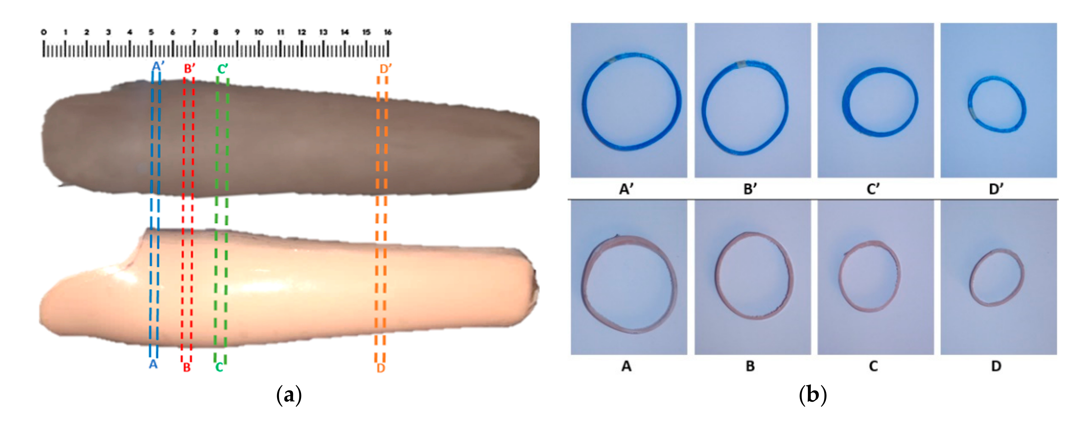
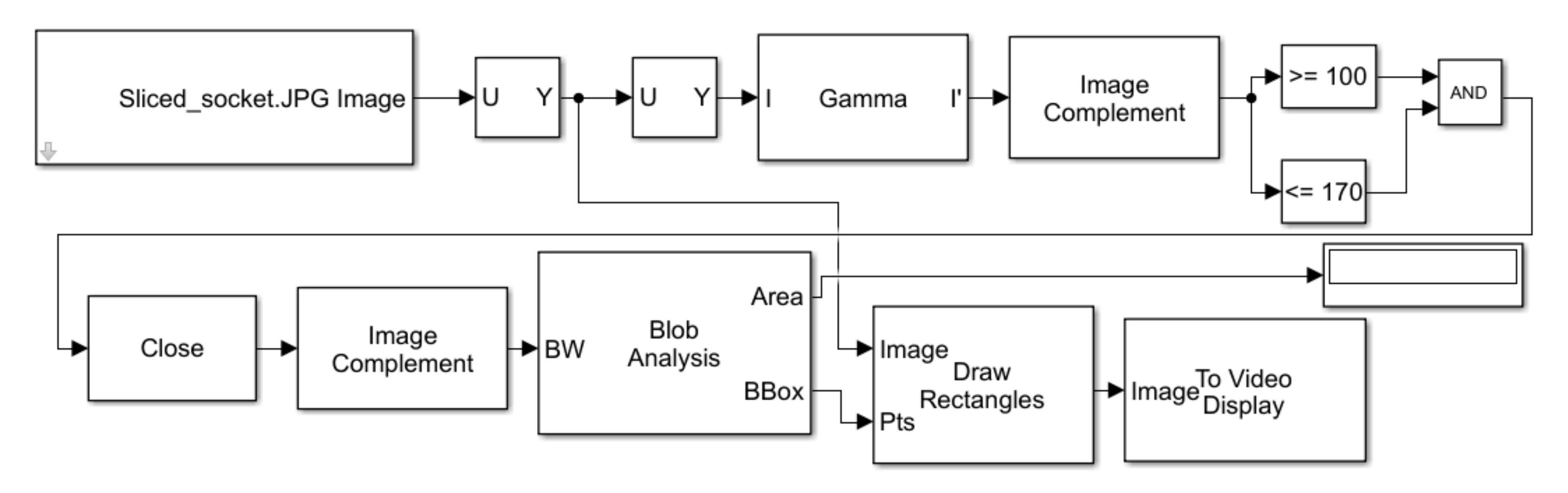
2.4. Segments Area Conformity Analysis
In this section, the conventional casting and photogrammetry sockets that had been manufactured before are used as samples for sectional segment area analysis. First, the sockets were cut into four segments for each 5 mm thick, as shown in
Figure 6a. The A–A′ segments were cut 50 mm from the top point of the stump, followed with 15 mm interval segments B–B′, and 15 mm from segments B–B′ were segments C–C′. These three pairs of socket segments were the socket parts which directly fitted with the remaining hand stump. The D–D′ segments were cut with a 155 mm distance from the top. The comparison of the segments used for the image processing target is shown in
Figure 6b. After the segments from each socket were obtained, the area error was calculated using the image processing method with Simulink MATLAB R2017b software. Some previous literature has studied the image processing method for calculating area and other applications [
24,
25,
26,
27]. The calculated area resulted from the image processing method is reliable and produces a relatively small error.
Segment A was compared to segments A′, B to B′, C to C′, and D to D′. Using the image-processing feature on MATLAB/Simulink R2017b, the total pixels of the calibrator was used as a reference for calculating the area based on the total pixels obtained from the image processing results.
Figure 7 shows the calibrator with 5 cm × 5 cm size and the post image RGB processing of the calibrator, which was used to confirm the real area and the pixel generated in this study.
The image processing method was developed using the Simulink block diagram. The arrangement of the Simulink block diagram to generate the total pixel of the image is shown in
Figure 8, below. The acquired sliced prosthetic was converted into an intensity image. It was processed using image complement and morphological closing operations to produce a binary image. Blob Analysis was employed to compute the resulted area of the sliced prosthetic socket, shown in
Figure 6b.
From the image processing result, the total pixel on the calibrator is 239,845 and the surface area of the calibrator was 2500 mm
2 which can be derived as 95.9 pixels for each square millimeter. This total pixel from the calibrator will be used as a comparison with the total area generated from the segments. The steps for this method are as follows: arranging the Simulink block diagram; input the image of a segment to block diagram; then generate and compare the generated pixels to the calibrator. Generated total pixels from the socket′s segments are shown at the end of the block display. Coefficient 100 and 220 acquired from different boundary pixel color can be checked on the block video display. To obtain the total area in the target area of the segment is by comparing total pixel from the calibrator and total pixel on the segment. The formula is expressed in Equation (1).
The surface area error of the compared segments can be derived by the difference surface area generated of both socket segments, S′ and S, divided by the casting socket segment area, S. The mathematical form of the surface area error is shown in Equation (2), below.
3. Result and Discussion
Based on the experimental work performed by a study participant, these area errors are can still be tolerated by a user. Based on the results, photogrammetry techniques can be implemented for the development of a transradial prosthetic socket design with just using 20° increments, while the other research employed 10° increments for photo retrieval [
13]. The 20° increment reduces the number of images and time for processing the 3D model.
The results of both sockets by casting and photogrammetry methods are shown in
Figure 9a,b, respectively. The weight of the sockets is 244.5 g and 150.2 g for casting and photogrammetry, respectively. The manufacturing of transradial socket using the conventional casting method consumes two days in total and all of the processes still need some tools and direct contact from the maker. This also needs knowledge and experience of the maker, which is usually obtained after 3 years of study. Meanwhile, the photogrammetry-3D printing method needs fewer tools and it needs less man-hour time, because of the utilization of 3D printing. The photogrammetry process needs 2 h and 3 h for fabrication and rectification, respectively. The 3D printing processing for the socket is 14 h. It found that this method is more efficient and cost-effective than that of the conventional casting method.
When a study participant wore a conventional casting type of prosthesis socket, the respondent felt that the socket was cramped, so it pressed down on the elbows, and eventually the hand was aching. The hand could be bent optimally, and the socket surface felt to be soft because the socket was coated with EVA foam. Whereas, when using a 3D printing type prosthesis socket, the respondent felt more comfortable because it fit the stump, but the hand could not be bent optimally. The socket surface was rough but when we applied EVA foam, the socket was more comfortable. The pictures of the respondent using these sockets are shown in
Figure 10 below.
From the segment area measurement results using the developed Simulink block diagram for image processing technique, the surface area of each segment for both sockets can be obtained. The surface area errors obtained from the segments using the image processing method are shown in
Table 1.
From the resulted errors summarized in
Table 1, it shows the area error between segments A–A′, B–B′, C–C′, and D–D′. The largest error is found in segment C with account for 19.03%, while the smallest error is found in segment D which is 5.50%. Overall, this shows that the errors of the 3D printed segment and the casting are more than 5%. Although, in the previous study [
8], the authors stated that the socket area error can be tolerated no more than 5%, in this calculation, the socket area error exceeds 5% because the conventional casting socket model is used as a reference that is suspected to have errors due to conventional rectification techniques. This fact of error was obtained directly from the prosthetic expert′s information. The acquisition of the remaining hand image using digital camera contributes significantly to the error, since the images are not obtained with constant distance from the remaining hand. It is difficult to obtain the image with constant distance without using camera spinning frames.
4. Conclusions
The manufacturing of a 3D printed socket only takes less than a day. Based on the resulting socket, it was found that it is a more effective and applicable method for prosthetic socket manufacturing. For obtaining the optimal results of acquiring the photos/images, we used a digital camera with 20 megapixels, 4.3–180.6 mm focal length, f/3.5 aperture range, 125–1600 ISO range, and optical zoom. The cost for manufacturing the prosthetic hand socket using a photogrammetry-3D printer is cheaper than that of the socket, resulting from the conventional casting method. Based on the results, photogrammetry techniques can be implemented for the development of transradial prosthetic socket design. Although the comparison of the 3D printed socket segment with the casting socket segment has a significant error of 5% to 19%, when the respondent wore the socket with EVA foam, the 3D printed socket is still preferable to use.
We believe that the photogrammetry and image processing for computing the sliced area of prosthetic socket contributes to the resulted deviation. The 2D images of the remaining hand were not obtained with precisely constant distance due to the difficulty to develop a camera spinning frame. The manufacturing process of the prosthetic socket using a 3D printer will definitely follow the 3D model in CAD software. Based on the result when the study participant wore the resulting socket, the photogrammetry-3D printer method can be used as a faster and affordable fabrication technique for prosthetic hand socket manufacturing.
In future research, while measuring socket dimension errors, it needs to compare them with several conventional sockets of the same type and use rectification techniques from previous studies on middle limb topology, especially for transradial amputation. Besides, it is suggested to build some additional equipment, such as camera spinning frames, for more accuracy when taking photos for photogrammetry. The image processing technique for computing the area of the sliced prosthetic socket will be improved to achieve better accuracy.