Article

Meminductor Emulator Based on a Modified Antoniou’s Gyrator Circuit

by
Francisco J. Romero
1,*,
Manuel Escudero
2,
Alfredo Medina-Garcia
3,
Diego P. Morales
1 and
Noel Rodriguez
1
1
Department of Electronics and Computer Technology, Faculty of Sciences, University of Granada, 18071 Granada, Spain
2
Infineon Technologies Austria AG, 9500 Villach, Austria
3
Infineon Technologies AG, 85579 Neubiberg, Germany
*
Author to whom correspondence should be addressed.
Electronics 2020, 9(9), 1407; https://doi.org/10.3390/electronics9091407
Submission received: 19 July 2020 / Revised: 17 August 2020 / Accepted: 24 August 2020 / Published: 1 September 2020
(This article belongs to the Section Circuit and Signal Processing)

Abstract

:
In this work, we presented the design and simulation of a new flux-controlled meminductor emulator based on a modified version of the well-known Antoniou’s inductor simulator circuit. The constitutive theoretical equations of meminductance are presented and subsequently correlated with the electrical behavior of Antoniou’s circuit, hence illustrating its practical meminductive behavior with a proper selection of feedback impedances. After that, the feasibility of a practical implementation using off-the-shelf devices is illustrated firstly for a two-state meminductor and secondly for a continuous-state meminductor by means of SPICE simulations. It was also demonstrated that this emulator can operate at different frequencies and input signals constituting one of the simplest and most versatile meminductor emulators to date.

1. Introduction

Prof. L. Chua first presented the notion of a memristor (memory-resistor) in 1971, defining a new circuit element which established the relationship between flux (ϕ, time-integral of the voltage) and charge (q) [1]. The memristor produces a non-linear relation between the current (i) and voltage (v), where the memory effect is manifested through a characteristic pinched hysteresis loop in its iv curve. In recent times, with the advent of actual physical memristors [2,3,4,5], the topic of passive memory devices has raised a high interest for researches and it has generated transversal studies involving different science and technologies areas such as chaotic and logic circuits [6,7], or neuromorphic computing [8,9].
Nearly 40 years later, the concept of passive memory-devices (memdevices) was generalized, again by Chua, for capacitive and inductive non-linear systems [10], expanding the relation between the different physical magnitudes schematized in Figure 1. Thus, the memcapacitance (CM, memory-capacitance) established the electrical relation between the time-integral of the charge (σ) and the flux (ϕ), whereas the relation between the charge (q) and the time-integral of the flux (ρ) was defined by the meminductance (LM, memory-inductance).
Because of their inherent memory and dynamic storage ability, these devices are expected to play an important role in diverse fields of science and technology, such as non-volatile memories and simulations of learning, adaptive, and spontaneous behavior circuits [11]. In the particular case of meminductors, several works have reported promising results for future electronic circuits, e.g., adaptative filters [12], chaotic circuits for encryption [13] or neuromorphic computation [14]. However, the solid-state implementation of these latter devices (memcapacitor and meminductor), in contrast to memristors, presents a challenge due to the yet elusive nature of their physical existence. For this reason, the emulators of these devices are leading the way to envisage real-practical implementations until single-device solid-state demonstrators become available. Thus, different examples of memcapacitor and meminductor emulators implemented with off-the-shelf devices or based on mutator approaches have been presented in the literature [15,16,17,18,19,20,21], all of them following the same principle, the designing of a circuit which satisfies the constitutive equations of the emulated device.
Following this principle, in this work we addressed a simple approach to emulate a meminductor based on one of the most famous inductor electrical simulators: the gyrator circuit proposed by Antoniou almost 50 years ago [22] which, using two op-amps and five passive elements, has been widely used in the literature to emulate different systems, such as Chua’s circuit: a simple electronic circuit that exhibits classic chaotic behavior [23]. Thus, the emulator proposed in this work, in contrast to the aforementioned approaches collected in the literature, presents the advantage of not requiring any four-quadrant analog multipliers, current conveyors or memristive devices, which make it one of the simplest and cheapest meminductor emulators to date.
The manuscript is structured as follows: after this introduction, Section 2 presents the analytical relations between the modified Antoniou’s circuit and meminductance. Section 3 proposes a design valid for emulating a two-state meminductor as well as a continuous transition of inductances together with their electrical characterization. Section 4 illustrates the feasibility of the meminductor emulator to study neuromorphic applications with a long-term potentiation example, and finally, the main conclusions are drawn in Section 5.

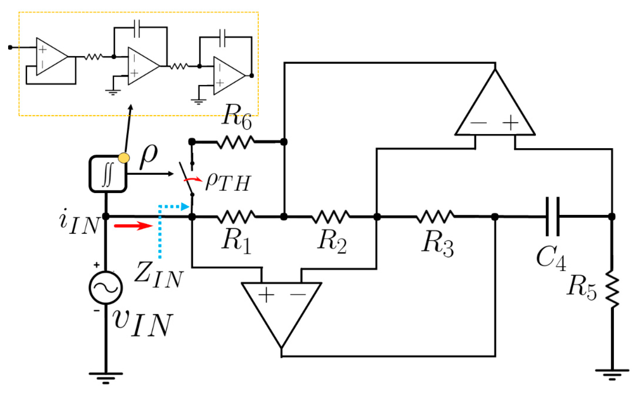
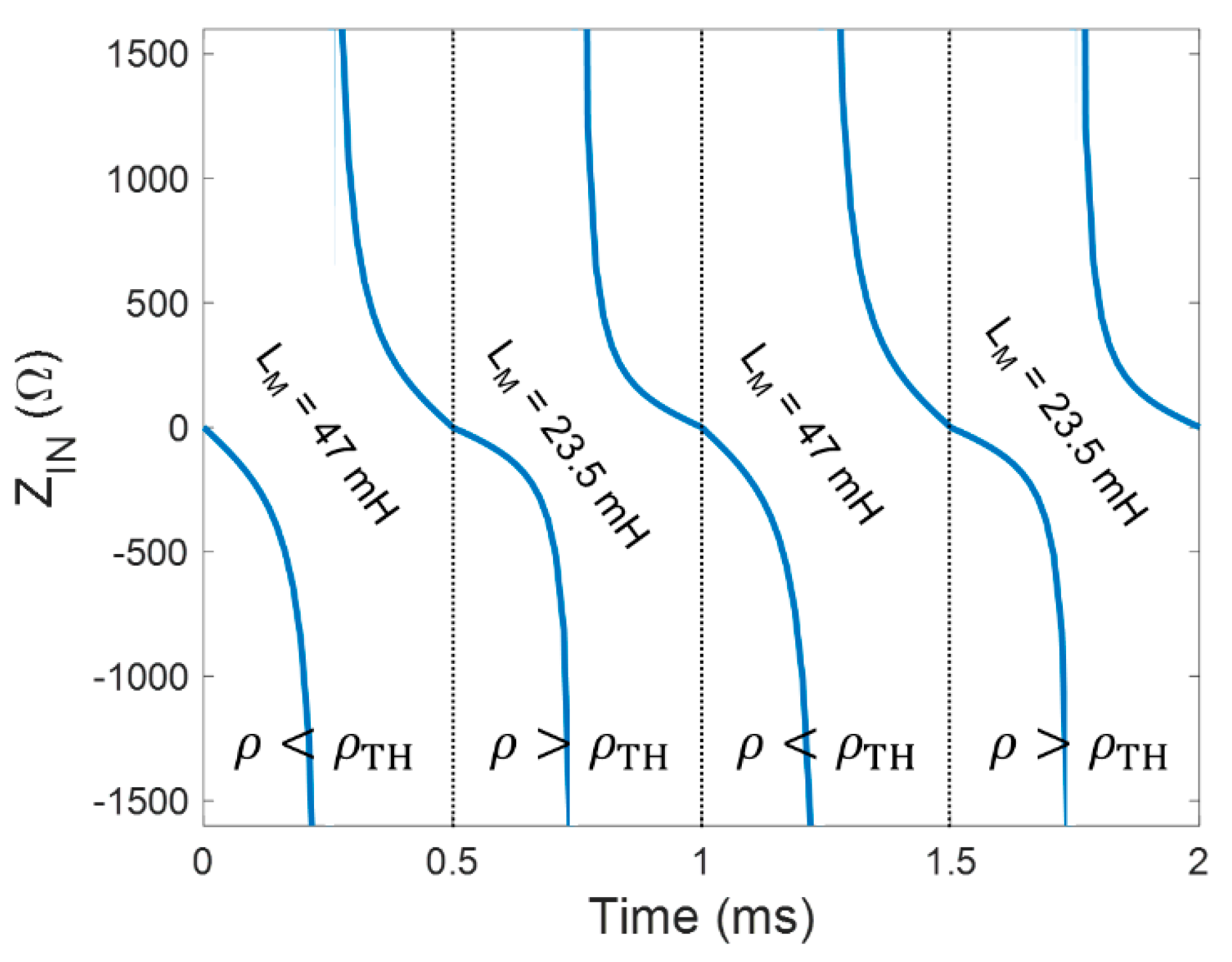
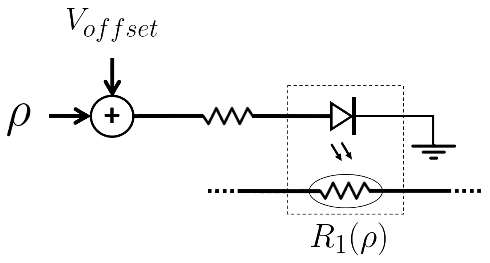
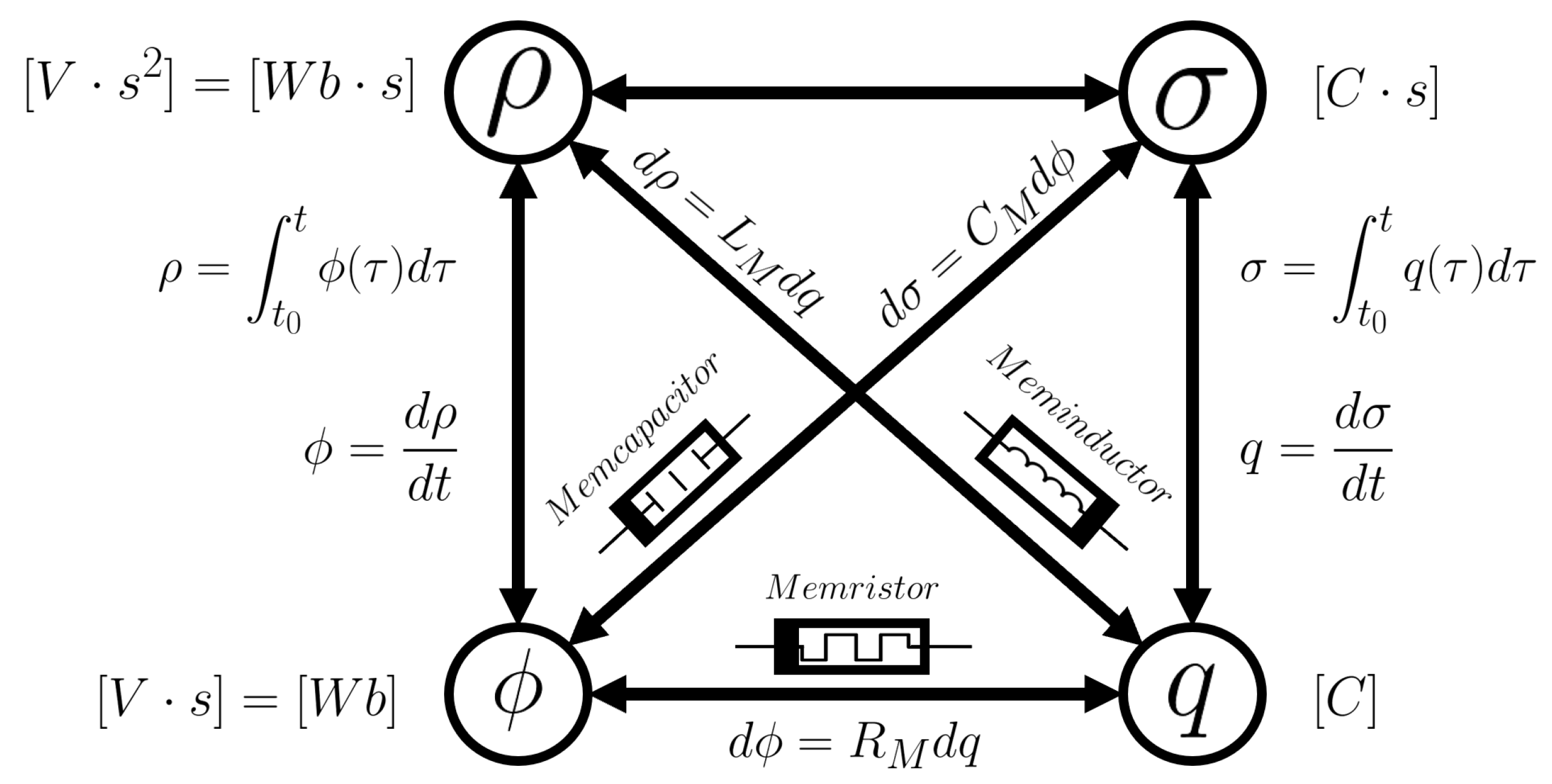
2. Meminductance and Antoniou’s Circuit

The canonical meminductor definition from Figure 1 can be generalized to a more general meminductance (LM) concept which establishes a non-linear nth-order relation between the current (i) and the flux (ϕ) that can be expressed in terms of a current-controlled meminductive system [10]:
ϕ ( t ) = L M ( x n , i ,   t )   i ( t )
d x n d t = f M ( x n ,   i ,   t )
or a flux-controlled meminductive system:
i ( t ) = L M 1 ( x n ,   ϕ ,   t )   ϕ ( t )
d x n d t = f M ( x n ,   ϕ ,   t )
where t is the time and x n the history (nth-order state-vector) of the system.
The first-order meminductive system whose inductance only depends on the time-integral of the input flux (TIF, ρ) is also known as flux-controlled meminductor and its definition is reduced to Equation (5):
i ( t ) = L M 1 ( ρ ) ϕ ( t )
with ρ = t 0 t ϕ ( τ ) d τ , proved that t 0 ϕ ( τ ) d τ = 0 .
Therefore, as Equation (5) indicates, the i-ϕ characteristic of meminductors is given by a pinched hysteresis loop, the current being zero whenever the input flux is zero.
In the case of flux-controlled meminductors, Equation (5) can be expressed as
i ( t ) = L M 1 ( t 0 t t 0 τ v ( τ ) d τ d τ ) ϕ ( t )
On this basis, hereinafter we demonstrate that the circuit proposed in this work, shown in Figure 2, can be modelled by Equation (6) when its different passive elements are properly selected, and therefore it can be used to emulate a grounded meminductor.
Antoniou’s simulator is widely described in the literature and it is considered one of the best options to simulate grounded inductors since it is very tolerant to the nonideal properties of the op-amps [24]. In addition, this configuration requires neither actual inductors (with the potential advantage of reduced form-factor, lower losses and cost) nor memristor for its implementation. In this case, to implement the meminductor emulator we drew on the equivalent input impedance (ZIN) of the circuit, considering the original Z1 as a TIF-dependent impedance, Z1(ρ), then:
Z I N = v I N i I N = Z 1 ( ρ ) Z 3 Z 5 Z 2 Z 4
From this basic circuit, a flux-controlled inductor could be modelled replacing Z1 by a TIF-dependent resistor (controlled by the time-integral of the input flux), Z4 by a capacitor C4 and finally, Z2, Z3 and Z5 by the resistors R2, R3 and R5, respectively. Therefore, Equation (7) can be expressed as
Z I N = v I N i I N = j ω R 1 ( ρ ) R 3 C 4 R 5 R 2
which corresponds to the impedance of a flux-controlled meminductor given by the following expression:
L ( ρ ) = C 4 R 3 R 5 R 2   R 1 ( ρ )
Moreover, this meminductor can be connected directly with the meminductance by means of the constitutive equation of the inductor:
v I N ( t ) = d d t ( L ( ρ ) i I N ( t ) )
which can also be expressed as:
d ρ I N ( t ) d t = φ I N ( t ) = v I N ( t ) d t = L ( ρ ) · i I N ( t )
The first term of Equation (10) can be further developed introducing the input charge (i.e., the charge circulating through the equivalent inductor):
d ρ I N ( t ) d t = d ρ I N ( q ) d q · d q ( t ) d t
Combining the definition of flux-controlled meminductance (Equation (5)) with Equations (11) and (12), the resulting meminductance seen at the input of the circuit is derived as follows:
L M = d ρ I N ( t ) d q ( t ) = L ( ρ ) · i I N ( t ) d q ( t ) / d t = C 4 R 3 R 5 R 1 ( ρ ) i I N ( t ) R 2 i I N ( t ) = L ( ρ )

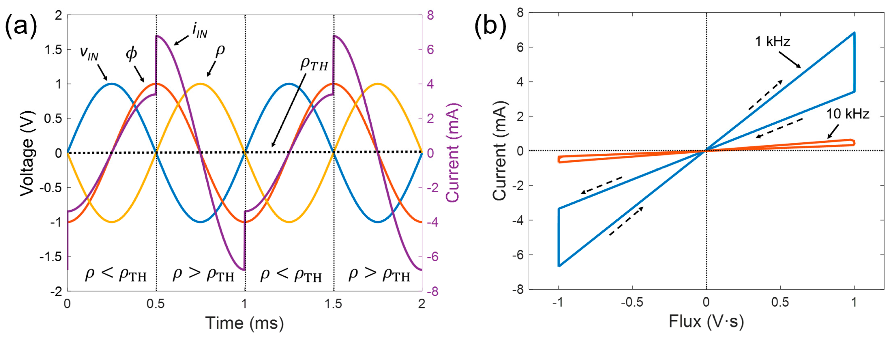
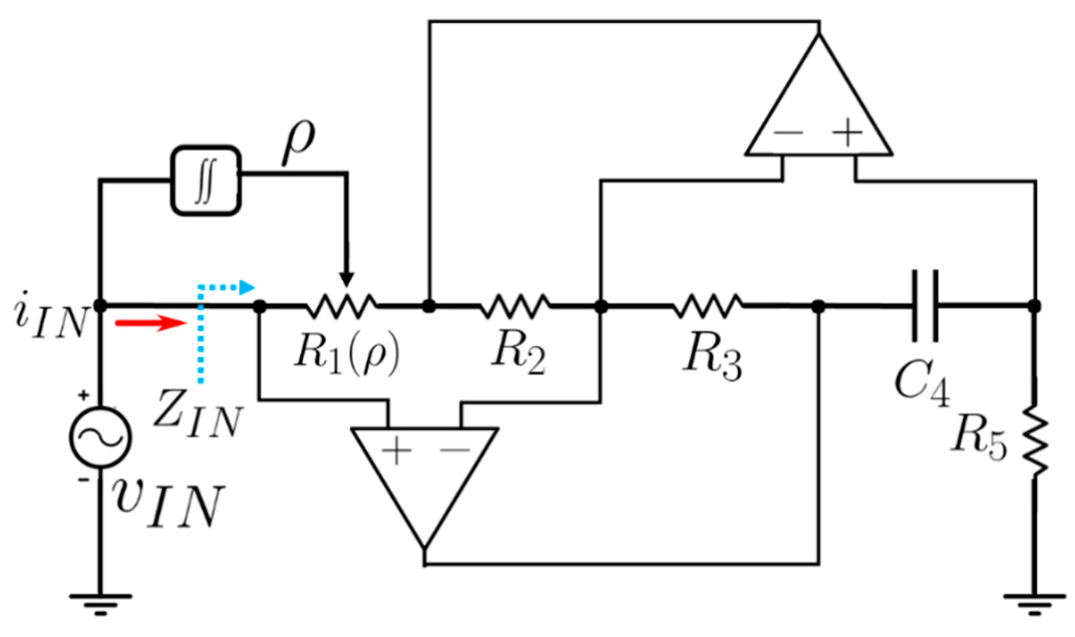
3. Meminductor Circuit Demonstrator

Aiming to illustrate the feasibility of this circuit, we developed a simple two-state meminductor demonstrator to study its electrical behavior based on the general schematic of Figure 2. In this circuit, R(ρ) takes two different values depending on the time-integral of the input flux (ρ) and the triggering value of the switch (triggering value of the TIF, ρTH). The double integrator circuit was simulated by means of two Miller integrators in cascade, considering that in a practical implementation a resistor should be used in the feedback loop to provide a DC feedback path, reducing the low frequency gain of the op-amp and hence avoiding the saturation of the output signal [24].
Therefore, as indicated in Equation (14), this particularized circuit yields a two-state meminductor. If the TIF is lower or equal to the triggering value (ρTH), then R6 is not connected in the feedback loop, otherwise R6 is connected in parallel with R1. Thus, according to Equation (13), the equivalent meminductance seen from the input terminal takes the following values:
L M ( ρ ) = { L H I G H = R 1 R 3 C 4 R 5 R 2                 ,           | ρ   ρ TH L L O W = ( R 1 | | R 6 ) R 3 C 4 R 5 R 2   ,           | ρ > ρ TH
The circuit of Figure 3 has been simulated with SPICE to confirm its meminductive behavior. For this, we considered the following values for the discrete components: R1 = R2 = R3 = R5 = R6 = 1 kΩ, C = 47 nF and ρTH = 0 V·s2, while the input was a sinusoidal signal, Vmsin(2πft), with Vm = 1 V considering two different frequencies, f = 1 kHz and f = 10 kHz. Thus, the resulting values of meminductance, according to Equation (14), would be LM = 47 mH for ρ ≤ ρTH and LM = 23.5 mH for ρ > ρTH.
The results shown in Figure 4 corroborate the two-state meminductive behavior of the proposed circuit. On the one hand, Figure 4a depicts the relevant signals of the circuit implemented. As seen, and in agreement with Equation (5), the input current takes the same waveform that the input flux (ϕ) but modulated according to the two values of meminductance as a function of its time time-integral (ρ). On the other hand, the i-ϕ plot, represented in Figure 4b, depicts the closed pinched hysteresis loop passing through the origin, which is the signature of meminductors [10]. It can also be noted that, as expected and as occurs for memristor and memcapacitors, the hysteresis collapses with increasing frequency [10,25,26].
The time-domain impedance of a time-dependent inductor (ZL(t) = vL(t)/iL(t)) can be determined from the fundamental relationship between flux and inductance:
ϕ L ( t ) = L ( t ) · i L ( t )
which, considering a sinusoidal input voltage (VL = Vm sin(ωt)) and a TIF-dependent inductance, produces the following time-domain impedance:
Z L ( t ) = v L ( t ) i L ( t ) = v L ( t ) ϕ L ( t ) · L ( ρ ) = v L ( t ) v L ( t ) d t · L ( ρ ) = ω L ( ρ ) tan ( ω t )
This equation matches with the results obtained for the time-domain input impedance extracted from the simulations presented above, as shown in Figure 5. It can be noted that the input impedance corresponds to two different values of inductance according to the time-integral of the input-flux and both Equations (14) and (16).
Once the operation of the circuit has been exposed, hereafter we demonstrate that this circuit could also be further extended to a continuous transition of inductances (instead of discrete states) using the configuration shown in Figure 6. For that, we considered Z1 as a TIF-controlled resistor whose values are given by Equation (17), while the rest of the components remain unchanged with respect to the previous configuration.
R 1 ( ρ ) = R 0 + K · ρ
For the simulations we considered R0 = 2 kΩ and the constant factor K = 1 kΩ to satisfy that R1,max = 3 kΩ and R1,min = 1 kΩ, given that ρ was normalized as |ρ| ≤ 1. Under this configuration, and as represented in Figure 7a,b, the circuit shown in Figure 6 also fulfils the constitutive equations of meminductors, but in this case, the behavior of the meminductor emulator does not present discrete transitions between states but rather continuous ones, since R1(ρ) is a continuous function of ρ, as indicated in Equation (17).
Moreover, to round up the flexibility of the proposed emulator, we present in Figure 8 the operation of the circuit shown in Figure 6 with a more complex excitation signal. In this particular example, we used the same continuous meminductance transition given by Equation (17), but considering a square input signal with a peak-to-peak amplitude of Vpp = 1 V and a frequency of 1 kHz.
Finally, we present a design of the continuous-states meminductor using commercial off-the-shelf devices. In this case, the TIF-controlled resistor is implemented by means of a photoresistive opto-isolator (which consists of an LED input optically coupled to a photocell, such as the model NSL-32 by Advanced Photonix [27]), as shown in Figure 9. With this particular optocoupler, we can achieve resistances from 40 Ω to 500 kΩ. A constant DC voltage (Voffset) is added to the TIF to prevent the LED turning off (since it would reduce the current thorough R1 down to values close to zero) and to work in the light-dependent resistor’s linear region [28].
The proper working of this approach using the same configuration as the previous examples with a Voffset = 3 V is demonstrated in Figure 10, where it can be appreciated that the circuit behaves as a continuous-state meminductor as a consequence of the change in R1(ρ) according to the TIF (taking values from ~60 Ω to ~150 Ω).

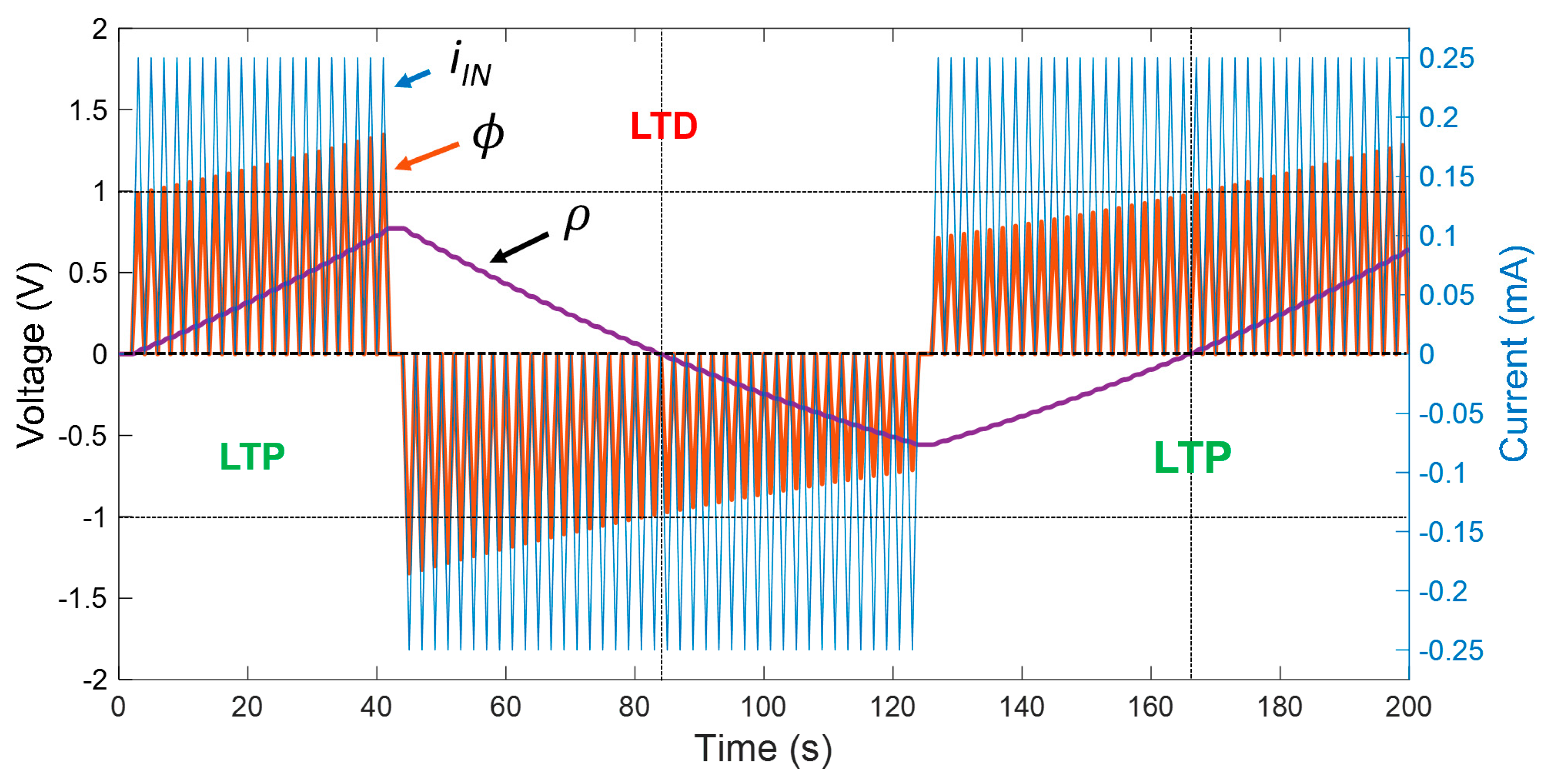
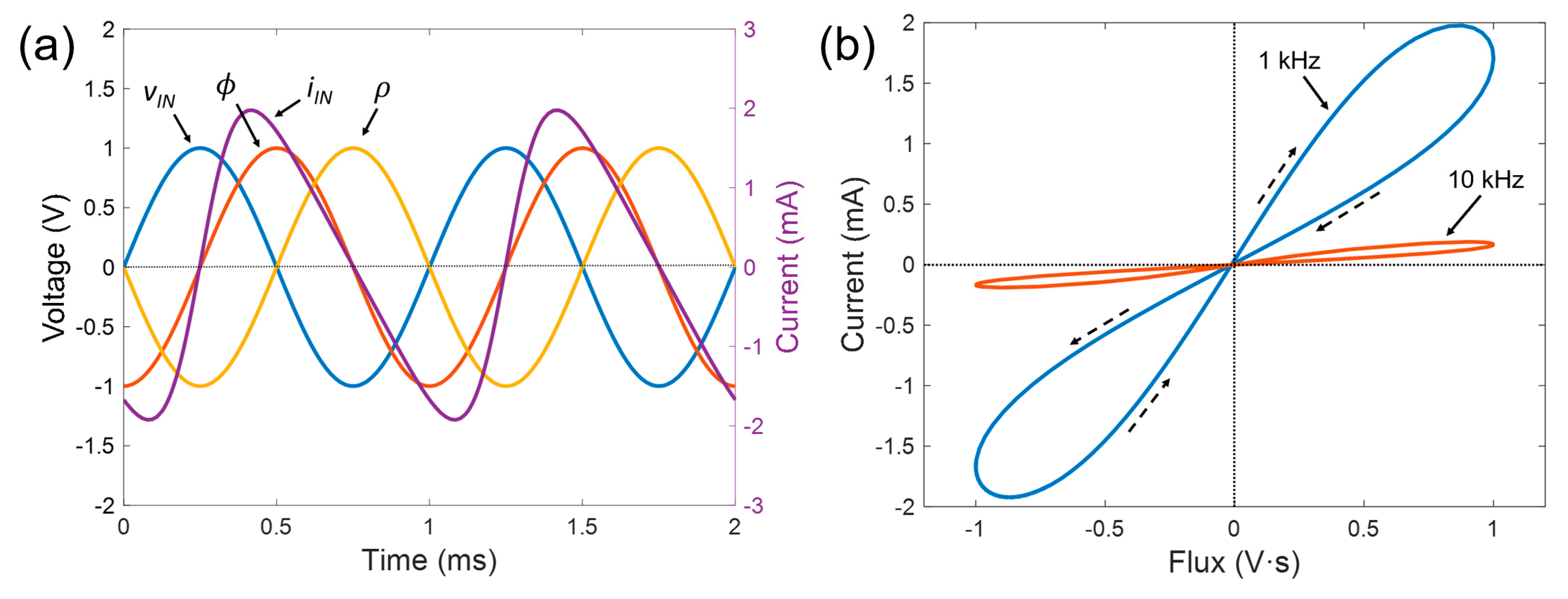
4. Long-Term Potentiation Example

In this last section, we demonstrated that this circuit is also feasible for the emulation of neuromorphic circuits. In neural activity, neurons act as signal spike generators to pass an electrical signal to another neuron, and synapses are the means by which they do so [29]. Then, in particular, we show in Figure 11 a long-term potentiation (LTP) and long-term depression (LTD) example, which emulates the long-term memory in biological systems. For that, we firstly applied pre-synaptic stimuli, modelled by successive current spikes with positive sign, progressively increasing the TIF of the device (potentiation). After that, a series of current spikes of negative value, acting as post-synaptic stimuli, induced the depression of the device, hence progressively reducing the TIF.
The confirmation of the learning/forgetting processes of the device can be recognized in the flux that the device stores and removes during each spike, reflecting an increase and decrease in the meminductance during the potentiation and depression, respectively. Thus, the repeated application of these pulses produces LTP or LTD behavior, in which the flux does not recover its pre-pulses value over a long period of time, and therefore neither does the meminductance.

5. Conclusions

In this work, a modified version of Antoniou’s inductor simulator was suited to implement the emulation of meminductive devices. It has been demonstrated that this approach can be used to simulate both discrete-state and continuous-state meminductors for different input signals and frequencies. The designed circuit is also general and can be implemented using off-the-shelf devices, which make it suitable for simple practical implementations in a wide range of applications, such as chaotic circuits or neuromorphic applications, as it has been illustrated by LTP and LTD examples.

Author Contributions

Conceptualization, F.J.R., D.P.M. and N.R.; methodology, D.P.M. and N.R.; software, F.J.R.; validation, M.E., A.M.-G., D.P.M. and N.R.; formal analysis, F.J.R., D.P.M. and N.R.; writing—original draft preparation, F.J.R. and N.R.; writing—review and editing, M.E., A.M.-G. and D.P.M.; funding acquisition, D.P.M., N.R. All authors have read and agreed to the published version of the manuscript.

Funding

This work was supported by the Spanish Ministry of Education, Culture, and Sport (MECD)/FEDER-EU through the grant FPU16/01451 and the project TEC2017-89955-P.

Conflicts of Interest

The authors declare no conflict of interest.

References

  1. Chua, L. Memristor-The missing circuit element. IEEE Trans. Circuit Theory 1971, 18, 507–519. [Google Scholar] [CrossRef]
  2. Strukov, D.B.; Snider, G.S.; Stewart, D.R.; Williams, R.S. The missing memristor found. Nature 2008, 453, 80–83. [Google Scholar] [CrossRef] [PubMed]
  3. Romero, F.J.; Toral-Lopez, A.; Ohata, A.; Morales, D.P.; Ruiz, F.G.; Godoy, A.; Rodriguez, N. Laser-Fabricated Reduced Graphene Oxide Memristors. Nanomaterials 2019, 9, 897. [Google Scholar] [CrossRef] [Green Version]
  4. Villena, M.A.; Hui, F.; Liang, X.; Shi, Y.; Yuan, B.; Jing, X.; Zhu, K.; Chen, S.; Lanza, M. Variability of metal/h-BN/metal memristors grown via chemical vapor deposition on different materials. Microelectron. Reliab. 2019, 102, 113410. [Google Scholar] [CrossRef]
  5. Zhu, K.; Liang, X.; Yuan, B.; Villena, M.A.; Wen, C.; Wang, T.; Chen, S.; Hui, F.; Shi, Y.; Lanza, M. Graphene-Boron Nitride-Graphene Cross-Point Memristors with Three Stable Resistive States. ACS Appl. Mater. Interfaces 2019, 11, 37999–38005. [Google Scholar] [CrossRef]
  6. Iu, H.H.C.; Yu, D.S.; Fitch, A.L.; Sreeram, V.; Chen, H. Controlling Chaos in a Memristor Based Circuit Using a Twin-T Notch Filter. IEEE Trans. Circuits Syst. I Regul. Pap. 2011, 58, 1337–1344. [Google Scholar] [CrossRef]
  7. Xia, Q.; Robinett, W.; Cumbie, M.W.; Banerjee, N.; Cardinali, T.J.; Yang, J.J.; Wu, W.; Li, X.; Tong, W.M.; Strukov, D.B.; et al. Memristor−CMOS Hybrid Integrated Circuits for Reconfigurable Logic. Nano Lett. 2009, 9, 3640–3645. [Google Scholar] [CrossRef]
  8. Prezioso, M.; Merrikh-Bayat, F.; Hoskins, B.D.; Adam, G.; Likharev, K.K.; Strukov, D.B. Training and operation of an integrated neuromorphic network based on metal-oxide memristors. Nature 2015, 521, 61–64. [Google Scholar] [CrossRef] [Green Version]
  9. Azghadi, M.R.; Linares-Barranco, B.; Abbott, D.; Leong, P.H.W. A Hybrid CMOS-Memristor Neuromorphic Synapse. IEEE Trans. Biomed. Circuits Syst. 2017, 11, 434–445. [Google Scholar] [CrossRef] [Green Version]
  10. Di Ventra, M.; Pershin, Y.V.; Chua, L.O. Circuit Elements With Memory: Memristors, Memcapacitors, and Meminductors. Proc. IEEE 2009, 97, 1717–1724. [Google Scholar] [CrossRef] [Green Version]
  11. Wang, G.-Y.; Jin, P.-P.; Wang, X.-W.; Shen, Y.; Yuan, F.; Wang, X.-Y. A flux-controlled model of meminductor and its application in chaotic oscillator. Chin. Phys. B 2016, 25, 090502. [Google Scholar] [CrossRef]
  12. Driscoll, T.; Quinn, J.; Klein, S.; Kim, H.T.; Kim, B.J.; Pershin, Y.V.; Di Ventra, M.; Basov, D.N. Memristive adaptive filters. Appl. Phys. Lett. 2010, 97, 93502. [Google Scholar] [CrossRef] [Green Version]
  13. Yuan, F.; Wang, G.; Jin, P.; Wang, X.; Ma, G. Chaos in a Meminductor-Based Circuit. Int. J. Bifurc. Chaos 2016, 26, 1650130. [Google Scholar] [CrossRef]
  14. Pershin, Y.V.; Di Ventra, M. Neuromorphic, Digital, and Quantum Computation with Memory Circuit Elements. Proc. IEEE 2011, 100, 2071–2080. [Google Scholar] [CrossRef] [Green Version]
  15. Yu, D.S.; Liang, Y.; Chen, H.; Iu, H.H.C. Design of a Practical Memcapacitor Emulator without Grounded Restriction. IEEE Trans. Circuits Syst. II: Express Briefs 2013, 60, 207–211. [Google Scholar] [CrossRef]
  16. Romero, F.J.; Morales, D.P.; Godoy, A.; Ruiz, F.G.; Tienda-Luna, I.M.; Ohata, A.; Rodriguez, N. Memcapacitor emulator based on the Miller effect. Int. J. Circuit Theory Appl. 2019, 47, 572–579. [Google Scholar] [CrossRef]
  17. Sah, M.P.; Yang, C.; Budhathoki, R.K.; Kim, H.; Yoo, H.J. Implementation of a Memcapacitor Emulator with Off-the-Shelf Devices. Elektronika ir Elektrotechnika 2013, 19, 54–58. [Google Scholar] [CrossRef]
  18. Sah, M.P.; Budhathoki, R.K.; Yang, C.; Kim, H. A mutator-based meminductor emulator circuit. In Proceeding of the 2014 IEEE International Symposium on Circuits and Systems (ISCAS), Melbourne, VIC, Australia, 1–5 June 2014; pp. 2249–2252. [Google Scholar] [CrossRef]
  19. Yu, D.; Zhao, X.; Sun, T.; Iu, H.H.C.; Fernando, T. A Simple Floating Mutator for Emulating Memristor, Memcapacitor, and Meminductor. IEEE Trans. Circuits Syst. II Express Briefs 2019, 67, 1334–1338. [Google Scholar] [CrossRef]
  20. Sozen, H.; Cam, U. A Novel Floating/Grounded Meminductor Emulator. J. Circuits Syst. Comput. 2020, 2050247. [Google Scholar] [CrossRef]
  21. Zhao, Q.; Wang, C.; Zhang, X. A universal emulator for memristor, memcapacitor, and meminductor and its chaotic circuit. Chaos Interdiscip. J. Nonlinear Sci. 2019, 29, 013141. [Google Scholar] [CrossRef]
  22. Kumar, U.; Shukla, S.K.; Amiete. Analytical Study of Inductor Simulation Circuits. Act. Passiv. Electron. Compon. 1989, 13, 211–227. [Google Scholar] [CrossRef]
  23. Torres, L.A.B.; Aguirre, L.A. Inductorless Chua’s circuit. Electron. Lett. 2000, 36, 1915–1916. [Google Scholar] [CrossRef]
  24. Sedra, A.S.; Smith, K.C. Microelectronic Circuits; The Oxford Series in Electrical and Computer Engineering, 5th ed.; Oxford University Press: New York, NY, USA, 2004. [Google Scholar]
  25. Yuan, F.; Deng, Y.; Li, Y.; Wang, G. The amplitude, frequency and parameter space boosting in a memristor–meminductor-based circuit. Nonlinear Dyn. 2019, 96, 389–405. [Google Scholar] [CrossRef]
  26. Fouda, M.E.; Radwan, A.G. Meminductor Response Under Periodic Current Excitations. Circuits Syst. Signal Process. 2013, 33, 1573–1583. [Google Scholar] [CrossRef]
  27. NSL-32 Optoisolator Datasheet. Available online: https://lunainc.com/wp-content/uploads/2016/06/NSL-32.pdf (accessed on 27 August 2020).
  28. Wang, X.-Y.; Fitch, A.L.; Iu, H.H.C.; Sreeram, V.; Qi, W.-G. Implementation of an analogue model of a memristor based on a light-dependent resistor. Chin. Phys. B 2012, 21, 108501. [Google Scholar] [CrossRef]
  29. Majumdar, S.; Tan, H.; Qin, Q.H.; Van Dijken, S. Energy-Efficient Organic Ferroelectric Tunnel Junction Memristors for Neuromorphic Computing. Adv. Electron. Mater. 2019, 5, 1800795. [Google Scholar] [CrossRef] [Green Version]
Figure 1. Mem-elements defined from the relations between the charge (q) and the time-integral of the voltage (ϕ), (memristor); the time-integral of the charge (σ) and the time-integral of the voltage (ϕ), (memcapacitor); the time-integral of the flux (ρ) and the charge (q), (meminductor). Units are presented in brackets.
Electronics 09 01407 g001
Figure 2. Schematic of the meminductor emulator based on Antoniou’s circuit. The different passive elements are represented by their impedance (Zi; i = 1, ..., 4). Z(ρ) represents a time integral of the flux (TIF)-dependent impedance, while υIN, iIN and ZIN represent the input voltage, current and impedance, respectively.
Electronics 09 01407 g002
Figure 3. Schematic circuit of the two-state meminductor emulator.
Electronics 09 01407 g003
Figure 4. Simulation results of the two-state meminductor. (a) Signals extracted from the circuit of Figure 3 for a sinusoidal input signal (Vm = 1 V, f = 1 kHz) with R1 = R2 = R3 = R5 = R6 = 1 kΩ, C = 47 nF and ρTH = 0 V·s2. (b) Closed pinched hysteresis loop of the flux–current curve for different frequencies (f = 1 kHz and f = 10 kHz).
Electronics 09 01407 g004
Figure 5. Time-domain input impedance extracted using a sinusoidal input signal under the configuration presented in Figure 3.
Electronics 09 01407 g005
Figure 6. Schematic circuit for the continuous states meminductor emulator.
Electronics 09 01407 g006
Figure 7. Simulation results of the continuous-state meminductor. (a) Signals extracted from the circuit of Figure 7 for a sinusoidal input signal (Vm = 1 V, f = 1 kHz) with R2 = R3 = R5 = R6 = 1 kΩ, C = 47 nF and R1(ρ) as indicated in Equation (17). (b) Closed pinched hysteresis loop of the flux–current curve for different frequencies (f = 1 kHz and f = 10 kHz).
Electronics 09 01407 g007
Figure 8. Signals extracted from the simulation results of the continuous-state meminductor using a square input signal with an amplitude peak-to-peak of 1 V and a frequency of 1 kHz.
Electronics 09 01407 g008
Figure 9. TIF-controlled resistor implemented by means of a photoresistive opto-isolator. The schematic of both summing amplifier and double integrator circuit is not shown for simplicity.
Electronics 09 01407 g009
Figure 10. (a) Signals extracted from the simulation results of the continuous-state meminductor using a photoresistive opto-isolator as time-integral of the input flux (TIF)-controlled resistor. (b) Closed pinched hysteresis loop of the flux–current curve for an input frequency of f = 1 kHz.
Electronics 09 01407 g010
Figure 11. Pre-synaptic (iIN > 0) and post-synaptic (iIN < 0) current spikes applied to the meminductor, emulating neural stimuli. Long-term potentiation (LTP) and long-term depression (LTD) are reflected by the progressive increase and decrease in the TIF, respectively. Input flux (ϕ) reflects the change in the memory state.
Electronics 09 01407 g011

