Article

Entire Magnetic Integration Method of Multi-Transformers and Resonant Inductors for CLTLC Resonant Converter

1
School of Electrical and Information Engineering, Tianjin University, Tianjin 300072, China
2
State Grid Jiangsu Electric Power Company, Nanjing 210024, China
3
State Grid Nanjing Power Supply Company, Nanjing 210019, China
4
State Grid Tianjin Economic Research Institute, Tianjin 300210, China
*
Author to whom correspondence should be addressed.
Electronics 2020, 9(9), 1386; https://doi.org/10.3390/electronics9091386
Submission received: 7 July 2020 / Revised: 23 August 2020 / Accepted: 25 August 2020 / Published: 27 August 2020
(This article belongs to the Section Power Electronics)

Abstract

:
An entire magnetic integration methodology of high efficiency printed circuit board (PCB) winding transformer for CLTLC (capacitor-inductor-transformer-inductor-capacitor) resonant converter is presented. All magnetic components in the converter, including two resonant inductors and two transformers, are integrated into an improved EIE (E-type and I-type and E-type) core structure. According to the matrix transformer concept and uneven winding distribution, the novel structure can be obtained by introducing an air gap to the center core leg. Thus, the magnetizing inductance and leakage inductance of the transformer can be controlled easily through adjusting the air gap reluctances. In addition, both the detailed mathematical analysis and the reluctance model of the transformer have been studied. Furthermore, a four-layer printed circuit board winding structure is chosen. The related winding arrangement is also discussed in depth. Finally, a 1 kW prototype with the presented structure is implemented to verify the validity of the theoretical analysis. Experimental results demonstrate that the proposed structure guarantees high efficiency within the entire load range. Peak efficiency of 96.62% can be ensured.

1. Introduction

Featured with high frequency, high efficiency, high power density and low electromagnetic interference (EMI), resonant DC-DC converters have aroused widespread public concerns [1,2,3]. Owing to the quantities and diverse connection ways of passive components (including capacitors, inductors and transformers) in the resonant unit, the flexible resonant characteristics can be achieved. In view of the endless research on this kind of converters, the topologies could be numerous [4,5,6,7,8].
Moreover, with the rapid development of wide band gap semiconductor devices, the momentum towards high frequency, miniaturization and lightweight is further proposed for resonant DC-DC converters. The design of magnetic components, namely inductors and transformers, is the key factor to achieve the above targets. In general, the volume, weight and cost of the magnetic parts dominate the whole converter’s efficiency, power density and heat dissipation. Nevertheless, traditional magnetic components with litz wires and copper foils as their windings, possess some inherent limitations, such as large volume, high power losses and complex fabrication process. Thereby, it usually results in the difficulty of performance promotion. In contrast, the planar magnetic components with the printed circuit board (PCB) windings emerge as the promising candidates [9,10,11,12,13]. Different from the conventional core structure, the planar transformer based on the low-profile core can not only help reduce the size of the magnetics, but also enlarge the heat dissipation area to lower the temperature. Furthermore, this technology can offer the improved reliability of the manufacturing process, so as to ensure the good consistency of products. Besides, the planarization of the core also promotes the investigation of the planar windings. Therefore, the primary and secondary windings are closely coupled to reduce eddy current losses effectively.
Through the employment of the planar magnetic components, high efficiency and automatic production can be harvested simultaneously, especially for the resonant converters with more magnetic components in the resonant units. However, the issues of a large number of magnetic components and subsequent large volume still exist. As a result, further efforts need to be made.
Fortunately, magnetic integration technology has proven to be an effective means of addressing the above issues. It could integrate multiple magnetic parts into one module. In such way, the whole integrated module is functionally equivalent to these multiple magnetic components. Consequently, a large number of magnetic components can be effectively shrunk. And the resulting power density is improved as well [14,15,16].
A variety of integrating schemes are reported in [17,18,19,20,21]. In [17], an integrated module is constructed for two inductors. Through the utilization of phase-interleaved currents, the proposed structure holds advantages of lower size and losses. For the integration of inductor and transformer, some researchers have improved or combined the core structure to achieve preferable performances. An EIE (E-type and I-type and E-type) core geometry is presented and analyzed in [18] to integrate the discrete magnetic elements. The design approach can decouple the transformer and inductor successfully, leading to their independent operation and control. Thereby, lower footprint and higher efficiency are both acquired. Under some conditions, it is preferred to serve the leakage inductor as the desirable inductor to diminish the overall size. In consequence, selecting low-permeability material as a magnetic shunt is a good way to build the desirable leakage inductance. Literature [19] proposes a novel method to create a larger resonant inductor through the adoption of the magnetic shunt. In this case, the series-connected inductor can be effectively integrated with the transformer. In [20], the magnetic shunt is inserted in the middle of the core window to increase the leakage inductance. With this structure, the desirable leakage inductance can be gained by adjusting the relative permeability and thickness of the shunt. Typically, the employment of a magnetic shunt suffers from structural complexity as well.
In this paper, the CLTLC (capacitor-inductor-transformer-inductor-capacitor) multi-resonant converter with dual transformer structure proposed by [8] is taken as the research object. Beneficial from the specific structure, the fundamental and third-order harmonic active power can be transferred simultaneously within a wide frequency range. Besides, the full-range soft-switching characteristics and high conversion efficiency are both guaranteed. Despite the above merits, the multiple magnetic components within its resonant unit result in the complex fabricating process and large volume as well, which compromises its extensive applications. In this regard, this topology needs further investigation and improvement. Correspondingly, this paper presents an effective integration method with the improved EIE core structure to integrate all the discrete magnetic components. Due to the series connection of inductor and transformer, the leakage inductor can be used as the resonant inductor. Specifically, through adjusting the air gap reluctances of different core legs, the flexible and separate control of magnetizing inductance and leakage inductance can be well attained. In this way, the reduced volume of magnetic components, manufacturing simplicity and high conversion efficiency are all harvested. Finally, experimental results demonstrate the effectiveness of theoretical analysis and integrated design.
The specific arrangements of the article are structured as follows. In Section 2, the concept of matrix transformer and the idea of unbalanced winding distribution are firstly developed. Then, the reluctance model is built to verify the effectiveness of the novel transformer structure with a controllable leakage inductance. The winding arrangement and core structure are discussed in Section 3. Section 4 shows the corresponding experimental results. Then, Section 5 summarizes the whole paper.

2. Investigation of Magnetic Integration Solution

2.1. Investigation of Matrix Transformer

A multi-resonant soft-switching CLTLC DC-DC converter with traditional magnetic components was proposed in literature [8]. Its topology is redrawn in Figure 1. As shown, there are in total six elements in the resonant unit, including two resonant capacitors (C1, C2), two resonant inductors (L1, L2), and two high-frequency transformers (T1, T2). Besides, the half-bridge (S1S2) is adopted in the inverter unit, and the diode rectifier (D1D4) is employed in the rectifier unit. Beneficial from the reasonable placement of three resonant frequencies, not only the fundamental component but also the third-order harmonic component can be effectively transmitted. The resonant current utilization is greatly enhanced correspondingly.
However, the abovementioned magnetic components (including inductors and transformers) in the resonant unit are all discrete magnetic components. Even implemented with planar magnetics, they still take a large share both in number and volume, resulting in increased losses and deteriorated efficiency as well. To deal with this problem, this paper proposes an improved EIE core structure to integrate all these four magnetic components. Correspondingly, the volume and related losses of the magnetic components are greatly reduced, the performances of the converter are also improved. The detailed design method is described below.
Matrix transformer concept proposed by literature [21] is an effective way to improve the characteristics of the transformer. Its essence is the combination of a series of basic transformers (T1, T2, …, Tk), making them function equally as a single transformer T. Specifically, each elemental transformer owns a set of turns ratio (np1:ns1, np2:ns2, …, npk:nsk). Then, through the appropriate connection (namely in series or in parallel) of the primary and secondary windings of these transformers, the desired turns ratio (np:ns) can be satisfied.
The matrix transformer with PCB windings shows the eminent advantages of reduced leakage inductance and winding losses. Whereas, when this method is applied to the CLTLC converter, the number of transformers and the consequent core loss will increase. In this case, with the extra introduced transformer cores, the overall volume as well as the conversion efficiency of the converter, may not be promoted accordingly. Besides, this scheme only improves the performance of the transformer instead of the inductor. Furthermore, as indicated in [21], through the adoption of elemental transformers with fully even distribution windings, the flux passing through the center leg can be completely canceled after the winding rearrangement. In this way, the generated leakage inductance by the transformer is too small to serve as the resonant inductance. In particular, for the CLTLC converter, the external inductor component is still required, leading to the increase both in the number and volume of the magnetic components. Consequently, the integration degree of this converter needs to be further improved.

2.2. Investigation of Uneven Distribution Windings

As discussed above, the resonant inductor is connected in series with the transformer in CLTLC converter. Thus, serving the leakage inductor of the transformer as the resonant inductor is a good way to simplify the magnetic integration scheme.
In this section, to achieve better-integrated effect, further adjustment of the windings is considered to be conducted. To attain the expected leakage inductance, the magnetic flux uncoupled between primary and secondary windings should be created. Thus, the unevenly distributed winding is employed to construct the leakage inductance instead of the evenly distributed winding.
It is worth mentioning that, based on the parameter design method proposed in [8], the main specifications of a 1 kW prototype can be easily obtained. The turns ratios of T1 and T2 are 6:1 and 1:2, respectively. Resonant inductors L1 and L2 are 25 μH and 24 μH, respectively. The main parameters of the converter are listed in Table 2 in Section 4. Since the design process is not the focus of this paper and has been discussed in detail in [8], it will not be presented repeatedly here.
Take transformer T2 as an example, the derivate method is briefly described as follows. To start with, T2 is divided into two elemental transformers T21 and T22 with UI (U-type and I-type) cores, as shown in Figure 2. Their turns ratios are set at 3:3 and 1:5, respectively.
For each elemental transformer T21 and T22, their inductive electromotive force includes self-induction electromotive force and mutual-induction electromotive force [22]. To simplify the analysis, the following three assumptions are made to fulfill the design requirements without losing accuracy:
(1)
The permeability of the magnetic core is much greater than that of the air, so the core reluctance is negligible compared to the air reluctance.
(2)
Flux leakage in the air is very small and can be ignored as well.
(3)
Under the magnetic circuit analysis, the influence of the fringing flux of magnetic fields is not considered.
Then, the self-inductance and mutual-inductance matrices for these two transformers can be written as (1) and (2). Here, vp1, vp2 and vs1, vs2 are the primary-side voltages and secondary-side voltages of T21 and T22, respectively. ip1, ip2 and is1, is2 represent their corresponding currents. The reluctance of the air gap is defined as Rg and listed in (3). Where lg and Ac denote the air gap length and cross-sectional area of the core leg. μr and μ0 are the relative permeability and vacuum permeability, respectively.
Further, the above two transformers can be arranged in a specific way to ensure that the desirable turns ratio of 1:2 is guaranteed for transformer T2. Specifically, Figure 3 shows the corresponding connection way. As seen, for T21 and T22, both of their primary windings and secondary windings are connected in series. In this case, the original two UI cores are equivalently substituted with one EI (E-type and I-type) core. From Figure 3a, the relationship between voltage and current among these three transformers is expressed as (4). Where, vp and vs are the primary-side voltage and secondary-side voltage of T2. ip and is are the corresponding currents.
[ v p 1 v s 1 ]   =   [ 9 R g 9 R g 9 R g 9 R g ] [ d i p 1 d t d i s 1 d t ]
[ v p 2 v s 2 ]   =   [ 1 R g 5 R g 5 R g 25 R g ] [ d i p 2 d t d i s 2 d t ]
R g = l g μ r μ 0 A c
{ v p   =   v p 1   +   v p 2 v s   =   v s 1   +   v s 2 i p   =   i p 1   =   i p 2 i s   =   i s 1   =   i s 2
Combing (1)–(4), the resulted self-inductance and mutual-inductance matrix is
[ v p v s ] = [ L 11 L 12 L 12 L 22 ] [ d i p d t d i s d t ] = [ 10 R g 14 R g 14 R g 34 R g ] [ d i p d t d i s d t ]
L11 and L12 are the self-inductances of primary-side winding and secondary-side winding, respectively. L12 represents the mutual-inductance [22]. To calculate the magnetizing inductor Lm, primary leakage inductor Lk1 and secondary leakage inductor Lk2, the transformer T-mode is built. For transformer T2 in Figure 4, the magnetizing inductor is Lm2. The leakage inductors of the primary winding and secondary winding are denoted as Lk21 and Lk22, respectively.
From Figure 4, according to the Kirchhoff Voltage Law, the primary-side voltage vp can be obtained by
v p = L k 21 d i p d t   +   L m 2 d ( i p + n s n p i s ) d t = ( L k 21 + L m 2 ) d i p d t + ( n s n p L m 2 ) d i s d t
Then, the relationship between Lm2, Lk21 and L11, L12 can be calculated as
L 11   =   L k 2 1   +   L m 2
L 12   =   n s n p L m 2
Accordingly, by converting the magnetizing inductor to the secondary side, the expression of L22 can be acquired.
L 22   =   L k 22   +   ( n s n p ) 2 L m 2
By solving the derived Equations (5), (7)–(9), we can calculate Lm2, Lk21, Lk22 as follows.
L m 2   =   7 R g , L k 21   =   3 R g , L k 22   =   6 R g
It is obviously seen from (10) that, in addition to the magnetizing inductor Lm2, the integrated EI core structure depicted in Figure 3 also possesses the built-in leakage inductor Lk21 and Lk22. Moreover, all these three parameters are only inversely proportion to the air gap reluctance Rg. Furthermore, for the deformation of (10), we have
L k 21   =   3 7 L m 2 , L k 22   =   6 7 L m 2
Together with (10) and (11), with the mentioned structure shown in Figure 3, there is a direct and confirmed proportional relationship between the leakage inductance and magnetizing inductance. That is to say, when the required magnetizing inductance is obtained through adjusting the air gap reluctance, the leakage inductance is also determined accordingly and remained unchanged. With this structure, the magnetizing inductance and leakage inductance could not be controlled independently and flexibly. In order to control the magnetizing inductance and leakage inductance, the core structure still needs improvements.
Beneficial from the series connection of the resonant inductor and the transformer, the primary leakage inductor can function as the resonant inductor in both T1 and T2. Moreover, the influence of the secondary leakage inductance is not concerned in the following analysis. Specifically, transformer T2 owns relatively small shared power compared to T1, so the effect of its secondary leakage inductance is negligible. Transformer T1 is a step-down transformer with few secondary windings, thus its secondary leakage inductance can also be ignored in this case.
Based on Figure 3, an improved EI core structure is proposed and demonstrated in Figure 5. Compared to Figure 3, a new air gap with the length of lgb is introduced to the center leg of the E core. Whereas, the length of the air gap of side legs is set as lga. Moreover, the cross-sectional area of the center leg and side legs is defined as Ac′ and Ac, respectively. In such way, the desirable air gap reluctance can be achieved by modifying the cross-sectional area and the length of the air gap. In (12), the air gap reluctances of side legs and center leg are expressed as Rga and Rgb, respectively. Then, through the different combinations of Rga and Rgb, the magnetizing inductance and leakage inductance can be flexibly controlled. The detailed analysis process will be described in the next part.
R ga = l ga μ r μ 0 A c , R gb = l gb μ r μ 0 A c

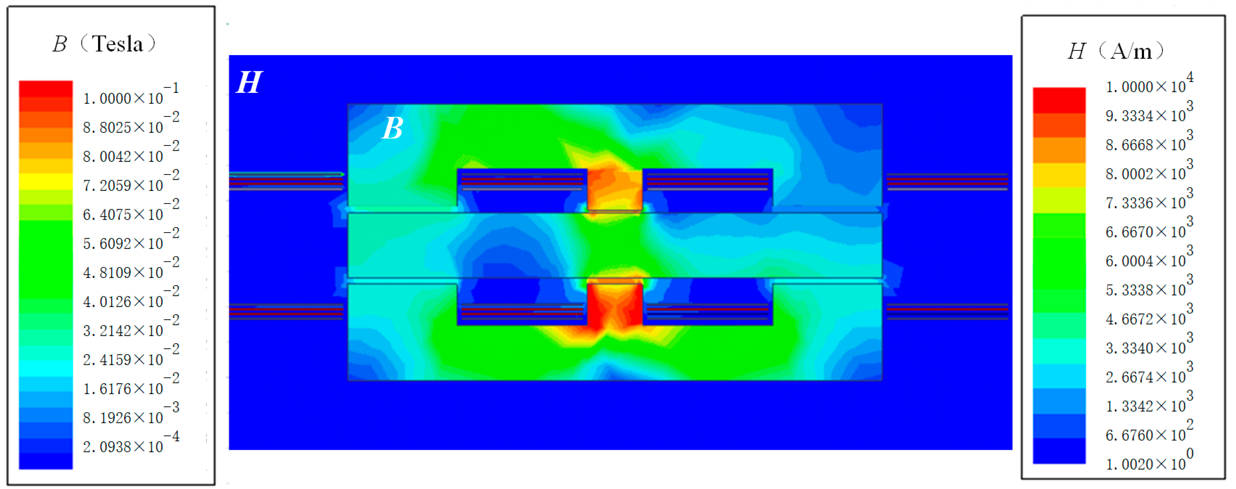
2.3. Reluctance Model

According to the improved integrated structure shown in Figure 5, the corresponding reluctance model can be established in Figure 6. The corresponding variables in the improved EI core structure are added by a superscript (′) to distinguish from the EI core structure shown in Figure 3. In other words, the primary leakage inductor and magnetizing inductor of T2 are redefined as Lk21′ and Lm2′, respectively. For precision, the assumptions are kept consistent with the previous analysis to simplify the model.
In Figure 6, np1, np2 and ns1, ns2 are the primary-side turns and secondary-side turns of the left-side leg and right-side leg, respectively.
Φ1, Φ3 and Φ2 are the flux flowing through the left, right and center legs, with their directions indicated by the yellow arrows in the figure. The magnetic flux of each leg can be derived and listed in (13) combined with Figure 6.
{ Φ 1   =   ( n p 1 i p 1 R ga + n p 1 i p 1 R gb + n p 2 i p 2 R gb ) ( n s 1 i s 1 R ga + n s 1 i s 1 R gb + n s 2 i s 2 R gb ) R ga ( R ga + 2 R gb ) Φ 2   =   n p 1 i p 1 n p 2 i p 2 + n s 2 i s 2 n s 1 i s 1 R ga + 2 R gb Φ 3   =   ( n p 1 i p 1 R gb + n p 2 i p 2 R ga + n p 2 i p 2 R gb ) ( n s 1 i s 1 R gb + n s 2 i s 2 R ga + n s 2 i s 2 R gb ) R ga ( R ga + 2 R gb )
According to the actual turns of each elemental transformers of T2, (13) can be simplified as
{ Φ 1   =   ( 3 R ga + 4 R gb ) i p ( 3 R ga + 8 R gb ) i s R ga ( R ga + 2 R gb ) Φ 2   =   2 i p   +   2 i s R ga + 2 R gb Φ 3   =   ( R ga + 4 R gb ) i p ( 5 R ga + 8 R gb ) i s R ga ( R ga + 2 R gb )
Besides, according to the Faraday law and T-model in Figure 5, the expressions of primary-side voltage and secondary-side voltage are
v p = L 11 d i p d t + L 12 d i s d t = n p d φ d t
v s = L 12 d i p d t + L 22 d i s d t = n s d φ d t
Further, the following expressions are listed for those two variables (Lm2′, Lk21′).
L k 21 + L m 2 = ( n p 1 φ 1 + n p 2 φ 3 ) | i s = 0 i p
L m 2 = ( n s 1 φ 1 + n s 2 φ 3 ) | i s = 0 i p
By solving the above equations, we can attain
{ L m 2 = 16 R ga 2 R ga + 2 R gb L k 21 = 4 R ga + 2 R gb 8 R ga
It is indicated by (19) that, for the structure depicted in Figure 5, both of the magnetizing inductance and leakage inductances of the transformer are related to the air gap reluctance Rga and Rgb. Therefore, for the desired magnetizing inductance and leakage inductance, the air gap reluctances Rga and Rgb can be determined.
In addition, from (12), the air gap reluctance is the function of the air gap length and the cross-sectional area of the core leg. The adjustment of these two variables can change the value of the air gap reluctance. On this basis, it is clear that the magnetizing inductance and leakage inductance can be flexibly controlled by changing the air gap length and cross-section area. In other words, the resonant inductor can be fully substituted with the leakage inductor of the transformer. Under this condition, the transformer and the resonant inductor are integrated into one core accordingly.
The above derivative process can also be applied to the transformer T1 and not discussed here. In summary, the superiority of the improved EI core geometry is obvious. Concretely, by changing the air gap reluctances of different magnetic legs, the magnetizing inductance and leakage inductance of the transformer can be ultimately determined. By this means, the leakage inductor is controllable and fully operated as the resonant inductor. Different from the conventional EI core, the leakage inductor can be controlled by the center leg in the improved core structure. In particular, if the center leg’s air gap reluctance is smaller compared to side legs, the more leakage flux will pass through, the higher the leakage inductor will be, and vice versa.
With this method, although the inductor losses are completely eliminated, the transformer losses increase as a result of the additional leakage flux flowing within the magnetic core. This may result in the bad thermal characteristic of the transformer. However, this design method is still instructive for the magnetic integration design of the multi-resonant converters.

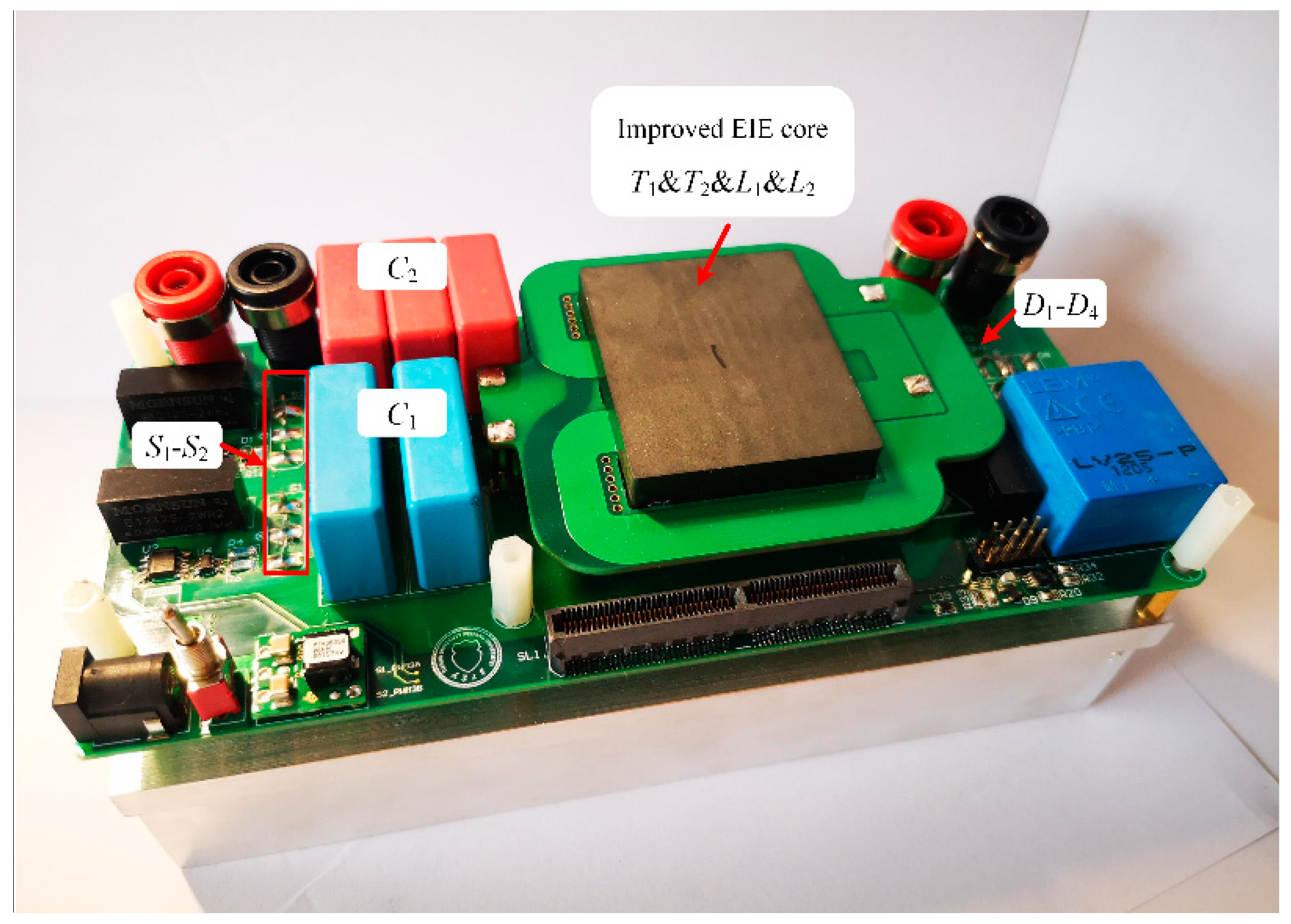
3. Winding Arrangement and Integrated Core Structure

The winding arrangement for the modified transformers T1 and T2 are illustrated in this section. In the following figures, the yellow arrow indicates the leakage flux direction within the core, the current direction is also marked. Based on the idea of uneven winding distribution, for both T1 and T2, more primary windings are placed on the left leg and more secondary windings are distributed on the right leg. Due to the redistributed windings, there is a flux passing through the center leg, which is not fully coupled between the primary and secondary windings. By definition, that is the leakage flux. The partial coupling of the flux results in leakage inductance [20]. In addition, the implementation of the four-layer PCB board is used for its relatively low cost and easy fabrication.
Figure 7 shows the detailed integration scheme of T2, which is composed of T21 and T22. With regard to T21, the top layer and bottom layer are the secondary windings, while the remaining two layers are the primary windings. Besides, the primary windings of T22 are located in Layer 3, and secondary windings are laid in Layer 1, Layer 2 and Layer 4. Furthermore, relatively good interleaving is ensured by this winding distribution to obtain the efficient conversion.
Similar to T2, the integration scheme with the detailed winding distribution of T1 is given in Figure 8. However, the winding distribution of T1 is quite different from that of T2. Specifically, the middle layers of primary windings are connected in series, the top and the bottom layers (Layer 1 and Layer 4) of secondary windings are in parallel. Due to the adoption of a parallel connection of windings, the current carrying capacity of the transformer is improved [21]. The winding arrangement of Layer 1 and Layer 4 is exactly the same.
From Figure 7 and Figure 8, the current direction of each element transformer is opposite, so is the direction of magnetic flux in the middle leg generated by them. Thus, the partial flux cancellation is obtained, and the length of the middle leg can be shrunk properly.
The detailed winding arrangement for the modified matrix transformers T2 and T1 are illustrated in Figure 9 and Figure 10, respectively. They correspond well to Figure 7 and Figure 8. In both figures, the yellow arrow indicates the current direction within the secondary windings. The red arrow denotes the current direction passing through the primary windings. Since the same windings are distributed in different PCB layers, vias is adopted to connect these layers.
As stated above, with the proposed improved EI core structure, a discrete transformer and a discrete resonant inductor can be simultaneously integrated into one core. Since there are four magnetic components (including two inductors and two transformers) in the resonant unit, to further enhance the properties of the transformer, an improved EIE core structure, shown in Figure 11, is proposed. As seen from this figure, when compared with two separate EI cores, one I-type core can be eliminated. Moreover, the remaining common I-type core provides a low reluctance path, thus each transformer can be operated independently. The improved EIE structure just combines two EI cores structurally, but does not change their winding distribution.
To validate the theoretical analysis, a two-dimensional finite element analysis (FEA) simulation model of the presented EIE magnetic integration scheme is built in Maxwell. The magnetic flux density B within the core and magnetic field H in the air are depicted in Figure 12. It is obvious that, due to the uneven winding distribution, a large amount of magnetic flux concentrates on the center leg. Based on the above analysis, most of it is leakage flux. Even so, the flux of the core is not saturated, and the maximum value of magnetic flux density is also limited reasonably. Compared with the core, there is less leakage flux in the air, having little impact on surrounding components, reducing EMI and eddy current losses accordingly.
In comparison, litz-wire-based transformers and inductors (discrete magnetics) are designed under the same parameters. The comparison between the improved EIE structure and discrete magnetics are given in Table 1. It should be noted that, the total volume and footprint of the magnetics only refer to the magnetic core, excluding the winding or skeleton.
From the comparison, the number of discrete magnetics is multiple, resulting in large volume and losses. This may place a restriction on its application and promotion. On this basis, the improved E core and I core structure, shown in Figure 13, is proposed to realize the complete integration of the magnetic elements in the resonant unit. Both the effective volume and footprint of magnetics are reduced. Moreover, the manufacture automation and good parasitic control can be gained with PCB magnetics. That is impossible for traditional litz wire magnetics.

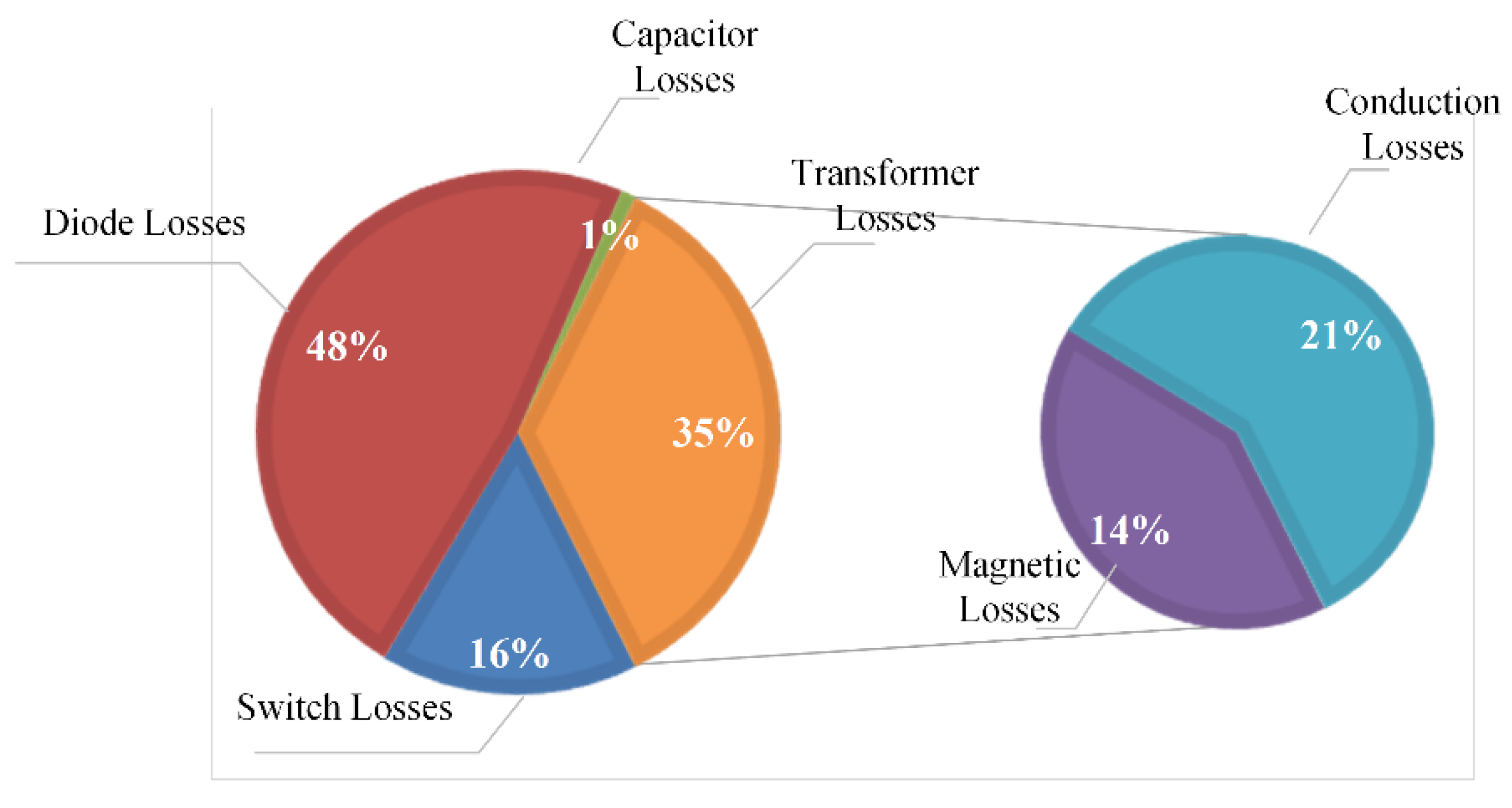
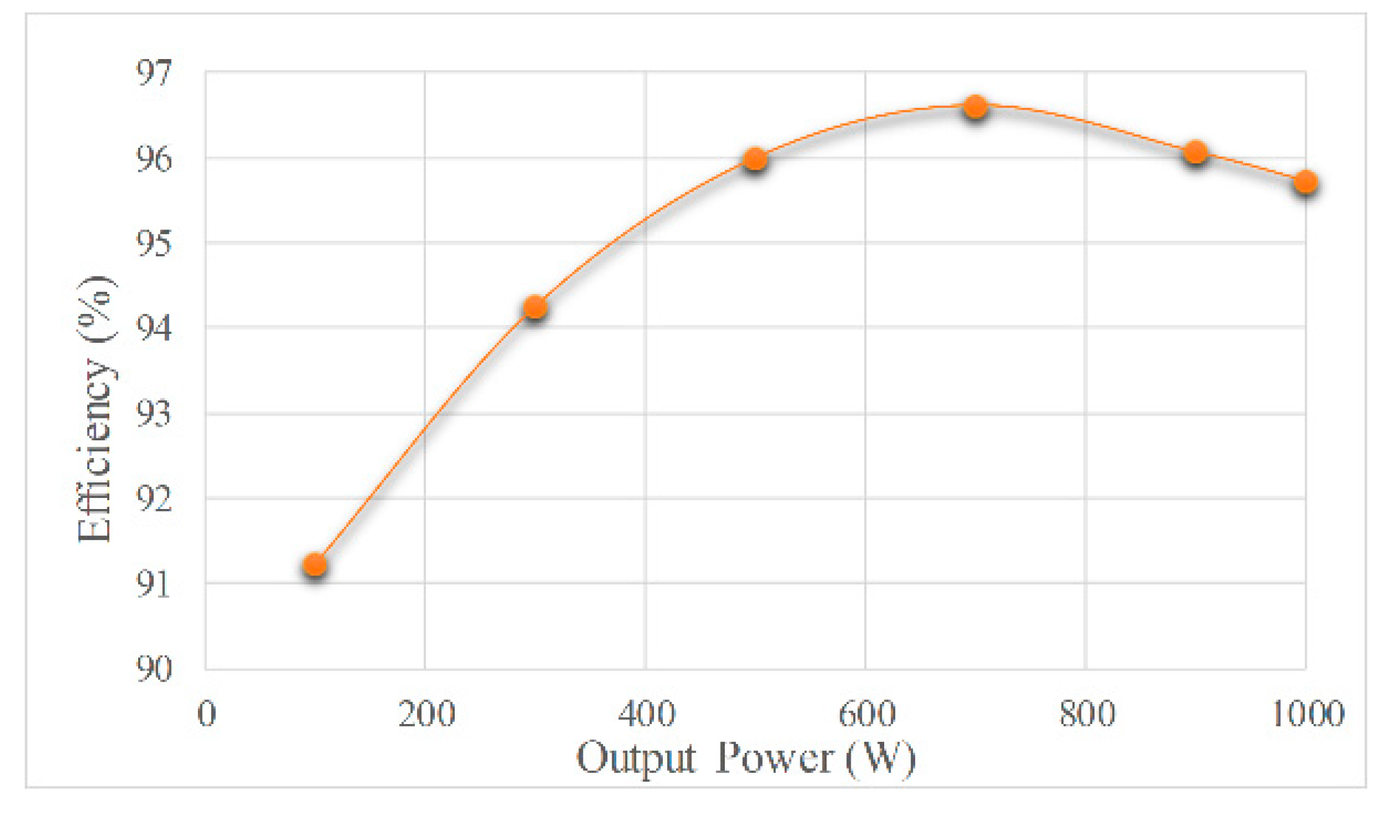
4. Experimental Result

To further verify the effectiveness, a 1 kW prototype with the proposed integrated core structure was built in the laboratory and shown in Figure 14. The involved components and their specifications are listed in Table 2.
Experiments are carried out under various loads of the rated working frequency and illustrated in Figure 15, Figure 16 and Figure 17. vGS denotes the driving signal, vS1 and iS1 represent the voltage and current of power switch S1. Similarly, vD1 and iD1 are defined as the corresponding quantities of diode D1. The currents passing through L1 and L2 are defined as iL1 and iL2.
Figure 15 shows the experimental results under the rated condition and the working frequency is 300 kHz. In this case, the input voltage is 400 V, and the output voltage is measured as 29.58 V. It matches well with the theoretical output voltage value (30 V). From Figure 15, the currents of power switches and diodes all exhibit saddle-wave form. It indicates that both the fundamental and third-harmonic components are adopted to transfer active power. The switch current is1 takes negative value at first, and then, turns positive. is1 lags behind vs1, that means, the anti-parallel diode is conducting earlier than the switch itself. So, the power switches realize the desirable zero voltage soft-switching (ZVS) characteristic. In Figure 15b, diodes also achieve the preferable zero current soft-switching (ZCS) operation. Such excellent soft-switching performances ensure a high conversion efficiency of 95.73%. Both of iL1 and iL2 exhibit the saddle-wave form, due to the superposition of the 1st and 3rd order components.
Experimental results under 50% load and 30% load are depicted in Figure 16 and Figure 17, respectively. As can be seen, power switches and diodes still demonstrate the preferable soft-switching operation. As a consequence, the switching losses are greatly restricted among the entire load range. The measured efficiency at 50% load and 30% load are 96% and 94.25%, respectively.
Under the rated condition, the calculated loss distributions are shown in Figure 18. As seen, the diode losses account for the highest proportion of the total losses. Beneficial from the preferable soft-switching features of the power switches, the switch losses are effectively restricted. Besides, the leakage inductor of the transformer fully serves as the resonant inductor, so the related inductor losses are completely removed. Meanwhile, the integrated core structure is alleviated with the core volume compared to discrete cores. And good response has been achieved in transformer magnetic losses. While the unbalanced winding distribution and additional leakage flux within the core may give rise to the transformer losses, but the excess losses are limited compared to its merit. In summary, relatively high-power conversion efficiency can still be guaranteed.
The measured efficiency curve under different output power is plotted in Figure 19. As seen, the CLTLC resonant converter with the proposed magnetic integration design could reach a peak efficiency of 96.62% and maintain high conversion efficiency throughout. There are two main reasons for this advantage. For one thing, the eminent soft-switching features are ensured in the full load range. The switching losses are greatly restricted. For another, with the proposed structure, two transformers and two inductors are integrated into the improved EIE core geometry. Under this condition, both the size and losses of inductors are removed. It also contributes to the reduction of total magnetic losses. To sum up, the overall losses can be restricted and relatively high efficiency is achieved correspondingly.
Moreover, the comparison is conducted between the proposed structure and other topologies. The results are listed in Table 3.
It is clearly shown that each converter has its own pros and cons. They all show good characteristics under various working conditions. In this paper, CLTLC converter is taken as the research object to solve the problem of large number and volume of magnetic parts. All magnetic components are integrated into one core to achieve integration and miniaturization. With PCB magnetics, the manufacture automation and good parasitic control can be realized. Meanwhile, the outstanding soft-switching performances are obtained for both the diodes and power switches. The third order harmonics can be effectively transmitted by appropriate parameter design. Thus, the overall efficiency can be ensured.

5. Conclusions

The CLTLC multi-resonant converter suffers from the problems of multiple magnetic components, large volume and high-power losses. To deal with the above issues, an entire magnetic integration method with the improved EIE core structure is designed in this paper. This scheme could integrate two transformers and two inductors into one core successfully. Rather than the evenly distributed winding in matrix transformer, the uneven winding distribution is adopted to increase the leakage inductance. By introducing an air gap to the middle core leg, the flexible control of the transformer’s magnetizing inductor and leakage inductor can be realized. Moreover, the detailed mathematical analysis and reluctance model are elaborated to validate the feasibility of the proposed structure. Besides, the detailed winding arrangement is given and the related simulation model is established in Maxwell software. In the end, a 1 kW prototype is built in the laboratory. The converter achieves preferable soft-switching characteristics within the entire load range and guarantees high conversion efficiency throughout. The peak efficiency reaches 96.62%.

Author Contributions

Conceptualization, R.L.; Formal analysis, R.L. and F.H.; Resources, Y.W.; Software, Q.C.; Validation, Z.M. All authors have read and agreed to the published version of the manuscript.

Funding

This research was funded by the National Key R&D Program of China (Grant: 2018YFB0904700).

Conflicts of Interest

The authors declare no conflict of interest.

Abbreviations

The following abbreviations are used in this manuscript:
PCBprinted circuit board
CLTLCcapacitor-inductor-transformer-inductor-capacitor
UIU-type and I-type
EIE-type and I-type
EIEE-type and I-type and E-type

References

  1. Yi, K. Capacitive Coupling Wireless Power Transfer with Quai-LLC Resonant Converter Using Electric Vehicle’s Windows. Electronics 2020, 9, 676. [Google Scholar] [CrossRef] [Green Version]
  2. Jia, P.; Yuan, Y. Analysis and Implementation of LC Series Resonant Converter with Secondary Side Clamp Diodes under DCM Operation for High Step-Up Applications. J. Power Electron. 2019, 19, 363–379. [Google Scholar]
  3. Shen, Y.; Wang, H.; Shen, Z.; Yang, Y.; Blaabjerg, F. A 1-MHz Series Resonant DC-DC Converter with a Dual-Mode Rectifier for PV Microinverters. IEEE Trans. Power Electron. 2018, 34, 6544–6564. [Google Scholar] [CrossRef] [Green Version]
  4. Yi, K. Output Voltage Analysis of Inductive Wireless Power Transfer with Series LC and LLC Resonance Operations Depending on Coupling Condition. Electronics 2020, 9, 592. [Google Scholar] [CrossRef] [Green Version]
  5. Chen, Y.; Wang, H.; Hu, Z.; Liu, Y.-F.; Liu, X.; Afsharian, J.; Yang, Z. LCLC Converter With Optimal Capacitor Utilization for Hold-Up Mode Operation. IEEE Trans. Power Electron. 2018, 34, 2385–2396. [Google Scholar] [CrossRef]
  6. Wu, H.; Jin, X.; Hu, H.; Xing, Y. Multielement Resonant Converters with a Notch Filter on Secondary Side. IEEE Trans. Power Electron. 2015, 31, 3999–4004. [Google Scholar] [CrossRef]
  7. Guan, Y.; Wang, Y.; Xu, D.G.; Wang, W. A 1 MHz Half-Bridge Resonant DC/DC Converter Based on GaN FETs and Planar Magnetics. IEEE Trans. Power Electron. 2017, 32, 2876–2891. [Google Scholar] [CrossRef]
  8. Wang, Y.-F.; Han, F.; Yang, L.; Wang, C.; Chen, B.; Xu, R. A Novel D-CLT Multi-Resonant DC-DC Converter with Reduced Voltage Stresses for Wide Frequency Variation Applications. IEEE Trans. Power Electron. 2018, 34, 4509–4523. [Google Scholar] [CrossRef]
  9. Ouyang, Z.; Andersen, M.A.E. Overview of Planar Magnetic Technology—Fundamental Properties. IEEE Trans. Power Electron. 2013, 29, 4888–4900. [Google Scholar] [CrossRef]
  10. Ouyang, Z.; Thomsen, O.C.; Andersen, M.A.E. Optimal Design and Tradeoff Analysis of Planar Transformer in High-Power DC-DC Converters. IEEE Trans. Ind. Electron. 2010, 59, 2800–2810. [Google Scholar] [CrossRef]
  11. Mu, M.; Lee, F.C. Design and Optimization of a 380–12V High-Frequency, High-Current LLC Converter with GaN Devices and Planar Matrix Transformers. IEEE J. Emerg. Sel. Top. Power Electron. 2016, 4, 854–862. [Google Scholar] [CrossRef]
  12. Buccella, C.; Cecati, C.; De Monte, F. A Coupled Electrothermal Model for Planar Transformer Temperature Distribution Computation. IEEE Trans. Ind. Electron. 2008, 55, 3583–3590. [Google Scholar] [CrossRef]
  13. Prieto, R.; Oliver, J.A.; Cobos, J.A.; Christini, M. Magnetic Component Model for Planar Structures Based on Transmission Lines. IEEE Trans. Ind. Electron. 2009, 57, 1663–1669. [Google Scholar] [CrossRef]
  14. Quirke, M.T.; Barrett, J.J.; Hayes, M. Planar magnetic component technology—A review. IEEE Trans. Compon. Hybrids Manuf. Technol. 1992, 15, 884–892. [Google Scholar] [CrossRef]
  15. Schauwers, J.-P.; Nunes, C.; Velaerts, B.; Robert, F.; Mathys, P. Planar transformer technology applied to AC/DC conversion. In Proceedings of the 21st International Telecommunications Energy Conference, INTELEC’99 (Cat. No.99CH37007), Copenhagen, Denmark, 9 June 1999. [Google Scholar]
  16. Quinn, C.; Rinne, K.; O’Donnell, T.; Duffy, M.; Mathuna, C.O. A Review of Planar Magnetic Techniques and Technologies. In Proceedings of the 16th Annual IEEE Applied Power Electronics Conference and Exposition, APEC 2001 (Cat. No. 01CH37181), Anaheim, CA, USA, 4–8 March 2001; pp. 1175–1183. [Google Scholar]
  17. Chen, W.; Lee, F.C.; Zhou, X.; Xu, P. Integrated planar inductor scheme for multi-module interleaved quasi-square-wave (QSW) DC/DC converter. In Proceedings of the 30th Annual IEEE Power Electronics Specialists Conference, Record (Cat. No.99CH36321), Charleston, SC, USA, 1 July 1999. [Google Scholar]
  18. Ouyang, Z.; Sen, G.; Thomsen, O.C.; Andersen, M.A. Analysis and Design of Fully Integrated Planar Magnetics for Primary–Parallel Isolated Boost Converter. IEEE Trans. Ind. Electron. 2012, 60, 494–508. [Google Scholar] [CrossRef] [Green Version]
  19. Biela, J.; Kolar, J.W. Electromagnetic integration of high power resonant circuits comprising high leakage inductance transformers. In Proceedings of the 2004 IEEE 35th Annual Power Electronics Specialists Conference (IEEE Cat. No.04CH37551), Aachen, Germany, 20–25 June 2004. [Google Scholar]
  20. Zhang, J.; Ouyang, Z.; Duffy, M.C.; Andersen, M.A.E.; Hurley, W.G. Leakage Inductance Calculation for Planar Transformers With a Magnetic Shunt. IEEE Trans. Ind. Appl. 2014, 50, 4107–4112. [Google Scholar] [CrossRef] [Green Version]
  21. Huang, D.; Ji, S.; Lee, F.C. LLC Resonant Converter with Matrix Transformer. IEEE Trans. Power Electron. 2014, 29, 4339–4347. [Google Scholar] [CrossRef]
  22. Erickson, R.W.; Maksimovic, D. Fundamentals of Power Electronics, 2nd ed.; Springer: Berlin, Germany, 2001. [Google Scholar]
  23. Imran, M.; Iqbal, S. A Wide Ouput Range HB-2LLC Resonant Converter with Hybrid Rectifier for PEV Battery Charging. IEEE Trans. Power Electron. 2017, 3, 520–531. [Google Scholar]
  24. Wang, H.; Li, Z. A PWM LLC Type Resonant Converter Adapted to Wide Output Range in PEV Charging Applications. IEEE Trans. Power Electron. 2018, 33, 3791–3801. [Google Scholar] [CrossRef]
  25. Wu, H.; Li, Y.; Xing, Y. LLC Resonant Converter with Semi-active Variable Structure Rectifier. IEEE Trans. Power Electron. 2016, 31, 3389–3394. [Google Scholar] [CrossRef]
  26. Li, M.; Ouyang, Z.; Andersen, M.A.E. High-Frequency LLC Resonant Converter with Magnetic Shunt Integrated Planar Transformer. IEEE Trans. Power Electron. 2018, 34, 2405–2415. [Google Scholar] [CrossRef]
  27. Li, B.; Li, Q.; Lee, F.C.; Yang, Y. A symmetrical resonant converter and PCB transformer structure for common mode noise reduction. In Proceedings of the 2017 IEEE Energy Conversion Congress and Exposition (ECCE), Cincinnati, OH, USA, 1–5 October 2017; pp. 5362–5368. [Google Scholar]
Figure 1. Topology of the capacitor-inductor-transformer-inductor-capacitor (CLTLC) converter.
Electronics 09 01386 g001
Figure 2. Transformer T2 with the uneven winding distribution. (a) Winding connection and UI (U-type and I-type) core structure of T21, (b) winding connection and UI core structure of T22.
Electronics 09 01386 g002
Figure 3. Equivalent winding connection way and EI (E-type and I-type) core structure of T2 (a) equivalent connection way of T2, (b) EI core structure of T2.
Electronics 09 01386 g003
Figure 4. T-model of the transformer T2.
Electronics 09 01386 g004
Figure 5. Improved EI core structure of T2.
Electronics 09 01386 g005
Figure 6. The equivalent reluctance model of the improved EI core structure.
Electronics 09 01386 g006
Figure 7. Integration scheme of T2.
Electronics 09 01386 g007
Figure 8. Integration scheme of T1.
Electronics 09 01386 g008
Figure 9. Winding arrangement for transformer T2 (a) Layer 1, (b) Layer 2, (c) Layer 3, (d) Layer 4.
Electronics 09 01386 g009
Figure 10. Winding arrangement for transformer T1. (a) Layer 1. (b) Layer 2. (c) Layer 3. (d) Layer 4.
Electronics 09 01386 g010
Figure 11. Integration scheme of CLTLC converter.
Electronics 09 01386 g011
Figure 12. Flux distribution of the improved EIE (E-type and I-type and E-type) core structure.
Electronics 09 01386 g012
Figure 13. Proposed E-type core and I-type core.
Electronics 09 01386 g013
Figure 14. Experimental prototype of the proposed converter.
Electronics 09 01386 g014
Figure 15. Experimental results at rated condition (a) waveforms of power switch S1, (b) waveforms of diode D1 and (c) waveforms of currents iL1, iL2.
Electronics 09 01386 g015
Figure 16. Experimental results at 50% condition (a) waveforms of power switch S1, (b) waveforms of diode D1.
Electronics 09 01386 g016
Figure 17. Experimental results at 30% condition (a) waveforms of power switch S1, (b) waveforms of diode D1.
Electronics 09 01386 g017
Figure 18. Loss contribution of the proposed converter at rated load.
Electronics 09 01386 g018
Figure 19. Efficiency curve under different output power.
Electronics 09 01386 g019
Table 1. Comparison between the improved EIE (E-type and I-type and E-type) core structure and discrete magnetics.
ParameterImproved EIE Core Structure (PCB Magnetics)Discrete Magnetics (Litz Wire)
Inductor L1IntegratedPQ2620
Inductor L2IntegratedPQ2620
Transformer T1Improved EI core structurePQ4040
Transformer T2Improved EI core structurePQ3535
Total volume (mm3)52,92095,760
Footprint (mm2)19603053.6
Total losses (W)15.122.7
Table 2. Main Parameters of the CLTLC (capacitor-inductor-transformer-inductor-capacitor) converter.
ParameterValues
Rated power P1 kW
Rated load R0.9 Ω
Rated switching frequency fs300 kHz
Input voltage Vin400 V
Output voltage Vo30 V
Inductor L125 μH
Inductor L224 μH
Turns ratio np′:ns6:1
Turns ratio np:ns0.5:1
Capacitor C15 nF
Capacitor C23 nF
Table 3. Comparison of performances among different topologies.
Topology DescriptionsInput Voltage VinRated Power PRated Operating Frequency fsPeak EfficiencyMagnetic Integration
HB-2LLC [23]400 V1.5 kW170 kHz95.21%No
PWM LLC [24]390 V1 kW100 kHz96.7%No
SA-VSR [25]400 V1.5 kW100 kHzAbove 95%No
LLC [26]380 V100 W1 MHzAbove 95%Yes
CLLC [27]350 V6.6 kW500 kHz97.8%Yes
CLTLC400 V1 kW300 kHz96.6%Yes

