Abstract
In this manuscript, an antenna on textile (jeans) substrate is presented for the WLAN, C band and X/Ku band. This is a wearable textile antenna, which was formed on jeans fabric substrate to reduce surface-wave losses. The proposed antenna design consists of a patch and a defected ground. To energize the wearable textile antenna, a microstrip line feed technique is used in the design. The impedance band width of 23.37% (3.4–4.3 GHz), 56.48% (4.7–8.4 GHz) and 31.14% (10.3–14.1 GHz) frequency bands are observed, respectively. The axial ratio bandwidth (ARBW) of 10.10% (4.7–5.2 GHz), 4.95% (5.9–6.2 GHz) and 10.44% (11.8–13.1 GHz) frequency bands are observed, respectively. A peak gain of 4.85 dBi is analyzed at 4.1-GHz frequency during the measurement. The SAR value was calculated to observe the radiation effect and it was found that its utmost SAR value is 1.8418 W/kg and 1.919 W/kg at 5.2/5.5-GHz frequencies, which is less than 2 W/kg of 10 gm tissue. The parametric study is performed for the validation of the proper functioning of the antenna.
1. Introduction
Flexible and wearable antennas that are lightweight, bendable, portable and reconfigurable are developing very fast in the present era. These antennas—based on the above characteristics—are being considered as an attractive option for conventional antennas, which are made of rigid substrates. An antenna is required for the wearable devices to function smoothly, providing wireless connectivity over a specific frequency band. Wearable wireless system applications cater to many areas; some of them are being used in personal communication, health care, military, entertainment and aeronautics [1,2]. The textile antenna came into existence by using the dielectric properties of the various fabric materials, focusing on the concept of the microstrip-patch antenna [3,4]. Wearable textile antennas play a noteworthy function in the body-area network (BAN) as a key component of the wearable devices [5,6,7]. There are some specific criteria that wearable antennas should be given close attention to. Usually, because of the wearable design, the size of the antenna should be as small, which is circularly polarized, and the antenna offers an impedance bandwidth/ARBW of 57.33% (8.46–15.26 GHz) and 28.64% (9.78–13.05 GHz), respectively. as possible, so it can be incorporated into clothing [8]. In addition, a wearable antenna should be flexible and lightweight, so that it can do well in bending and crumpled situations [9]. In order to find the correct value of substrate material, loss-tangent (tan δ), permittivity (εr) plays a key role in antenna technology [10]. To achieve the wide impedance bandwidth, high efficiency and flexibility it requires low value of permittivity (εr), which improves the impedance bandwidth by reducing the losses [11]. The defected ground structure (DGS) structure is utilized to improve the performance of the antenna [12,13], such as I-shape for WLAN applications, asymmetric slot for CP operation [14,15]. When the antenna is coming to the contact of human body, the antenna parameters such as dielectric constant may change [16,17]. The human body works as lossy component due to its biologic tissue property, which absorbs the energy of electromagnetic waves and get changed the performance parameter. SAR is an important parameter that determines the energy absorption ratio. According to FCC (Federal Communications Commission) US Standard the maximum limit of SAR is 1.65 W/kg based on 1 gm tissue and according to the IEC (International Electrotechnical Commission) European Standard the maximum limit for 10 g tissue is 2 W/kg.
In [18] a circular-shaped slotted textile-based antenna with partial ground structure is presented, which have an impedance bandwidth of about 46% and 41%, respectively. The authors in [19] presented a felt-textile-based wearable antenna for dual band operation at 2.4/5.2 GHz for WLAN application, which have maximum gain of 1.8 dBi/3.2 dBi. In [20] two different textile-based substrate (polyester and Jeans cotton) have presented for wearable antenna, the antenna offers frequency range from 2.25–2.74 GHz and 4.3–6.8 GHz for WLAN and WiMAX band applications. The authors in [21] have presented a gap coupled FR-4-based novel antenna using modified ground,
In this work, a novel compact jeans textile-based wearable antenna is presented. The antenna is showing triple band operation with an acceptably low value of SAR, which is desirable for the human body. In addition to, this antenna shows a circular polarization which enhances the capability of antenna and reduce the losses. For the user safety point, this antenna allows low SAR as per guidelines given by IEC (International Electrotechnical Commission). By considering above points this textile-based antenna differentiates itself from other antennas.
The whole article is structured in five different sections. The introduction of the whole article is described in Section 1. The proposed antenna structure with dimensions and other parameters is described in Section 2. Parametric analysis and optimization processes are explained in Section 3. The various results and discussions are presented in the Section 4. The conclusion of the manuscript is briefed in Section 5.
2. Materials and Methods
This section describes the material selection for the development of the proposed antenna. According to the property of material relative permittivity, the material has low permittivity if any, i.e., less than approximately 2. Hence, it has a capability to increase bandwidth of antenna by reducing the surface wave losses. It not only reduces the losses, but also provides material flexibility. Due to the flexibility of the material it can be integrated with human body with or without clothing for WBAN applications. In order to increase the bandwidth and reduce the losses, a textile material should have stumpy-surface resistance. In general, the resistance value of surface must be constant over entire structure of antenna. The textile substrate has some diverse effects, such as fluctuations in electric current. If these diversities are parallel to the surface-current value, there is no interruption to the propagation of electromagnetic waves. However, if the diversities interrupt the electric current flow, they may increase the value of surface resistance. The textile material is very much influenced by moisture content, which increases the permittivity of the material and also increases the losses. To develop the proposed antenna, an optimization process was applied to find the synthesized design. The finite element method, technique is adopted to solve the complete designing process using HFSS simulator. The proposed structure was also solved through finite integration in technique (FIT) using CSTMWS simulator. The measurement was done with Vector network analyzer inside the anechoic chamber.
The systematic design procedure of a wearable textile antenna is considered in five different considerations. In the first step of the process, we must select the appropriate substrate material. Then, in the second step, we must analyze the material characterization of the substrate, i.e., permittivity and loss tangent of the material. Moving towards the third step, information based on material the wearable antenna is optimized and simulated. In the fourth step, the physical implementation of the antenna as per fabrication process is considered. In the last step, real-time testing includes return-loss performance, gain, radiation pattern with SAR effect, bending effects and other performances for wearable antennas.
Textile Antenna Structure
The basic design process is shown in Figure 1. A jeans textile substrate of dimension WxL is taken here to implement the antenna structure. Two methods were used to find the value of dielectric constant of the material, which are as follows:
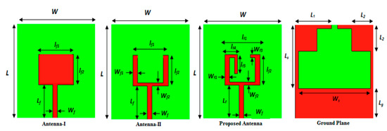
Figure 1.
Optimization process of anticipated antenna.
- Non-resonant methods;
- Resonance methods.
In non-resonant methods, generally it consists of reflection methods and transmission/reflection methods. In the reflection coefficient method, the reflection characteristic (ρ) of the electromagnetic (e–m) wave from free space to the sample material under testing to take out the value of the dielectric constant of the material sample. In contrast, in the second method, the value of dielectric constant is determined based on reflection from the sample and transmission through the sample. The resonance method was used to measure the dielectric constant of the sample with precision [22]. The thickness of substrate was 1 mm and loss tangent was 0.025. To create a simple rectangular patch, a conducting adhesive copper tape of dimension lf1 × lf2 was used. For the excitation of simple patch, a microstrip line of dimension lf × Wf was used, which had a 50 Ω characteristic impedance. Impedance-matching and bandwidth enhancement were dependent on defected ground plane. By using this concept, two rectangular slots with dimensions of (Ls − Lg) × Ws, (2L2 × Ws) and one notch (1 × 2 mm2) had etched from the ground plane. A rectangular notch was etched from the basic patch to enhance impedance bandwidth. After making u shape patch antenna, again continuing the evolution process, by turning the left vertical patch and inserting a metallic stub in the right vertical patch, impedance-matching performance had improved.
Table 1 shows the anticipated antenna parameters.

Table 1.
Antenna parameters and their values.
The antenna was simulated on HFSS and CSTMWS simulator and real-time measurements were performed with vector network analyzer in anechoic chamber to verify the corresponding results.
3. Parametric Study of Proposed Antenna
To present the proper antenna structure, the basic antenna was passed through the evolutionary process. Antenna I shows the basic structure of the textile antenna in which the upper part of antenna was the radiating part, whereas the lower part was the ground. In order to find good radiation characteristics, partial modified ground was used. A rectangular patch was removed from Antenna I to enhance the impedance bandwidth. By turning the left patch vertically, good S11 characteristics were obtained, which indicated better results than the first two designs. Different parametric analysis were completed to find the most suitable textile antenna design. At any given time, only one parameter was varied, and others were kept fixed. By using this concept, the following parametric analysis was completed giving a justified antenna structure.
3.1. Variation of the Feed Width
A good impedance match is required to ensure the proper operation of an antenna. It also requires a justified feed-width value of a microstrip line, which gives 50 Ω impedance value to present maximum transfer of electromagnetic waves. By varying the feed width from 1.5 mm to 2.5 mm, the return loss (<−10 dB) was also varying from 3 GHz to 15 GHz frequencies. The feed width value of 2.5 mm return loss (<−10 dB) is −42 dB at 11.8 GHz frequency and −25 dB is available near 6 GHz frequency whereas at 4.2 GHz frequency, return loss is shifted to −10 dB. Figure 2 shows that −42 dB return loss at 11.8 GHz was achieved for feed width of 2.5 mm, whereas the other feed values of 1.5 mm, 1.7 mm, 1.9 mm, 2.1 mm and 2.3 mm, return loss values were −24 dB, −25 dB, −22 dB and −30 dB, respectively.
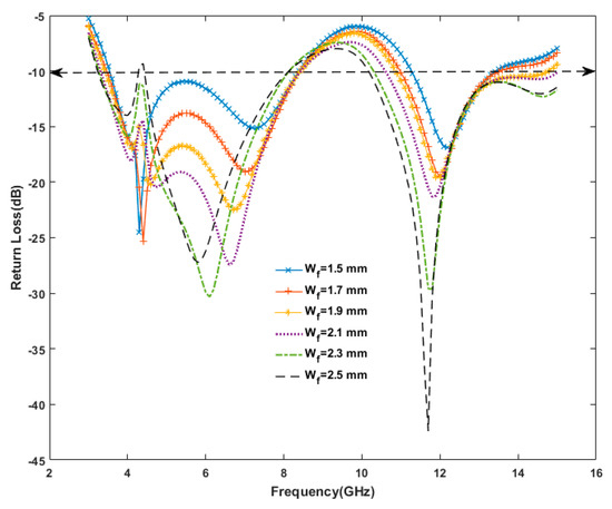
Figure 2.
Study of variation on feed width of textile antenna on the basis of return loss plot.
3.2. Effect of Variation on Wf2
Figure 3 shows the effect of variation on Wf2. The variation in Wf2 had significant effects on return loss performance as it varies from 0.8 to 1.8 mm. The performance of the proposed antenna was very good at Wf2 = 0.8 mm.
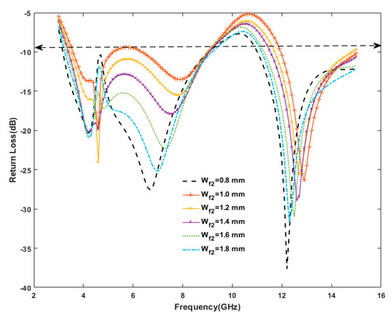
Figure 3.
Study of variation on Wf2 of textile antenna on the basis of return loss plot.
3.3. Effect of Variation on lf2
The return loss performance for various values of lf2 variation is given in Figure 4. By taking length variation from 6.2 mm to 7.2 mm antenna performance was analyzed. The resonance frequency shifted towards higher frequencies when the length of If2 was increased. It was clear that the performance of the proposed design was far better at lf2 = 7.2 mm.
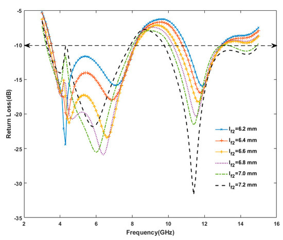
Figure 4.
Study of variation on lf2 of textile antenna on the basis of return loss plot.
3.4. Variation of the Substrate Height with 2.5-mm Feed Width
The resonant frequency was changed by increasing and reducing the height of the substrate. Figure 5 presents that −42.18 dB return loss was obtained at 11.7 GHz frequency with 1-mm substrate height. By reducing the substrate height of 0.8 mm, the return loss value was −37.64 dB, and resonant frequency shifted to 12.2 GHz. By increasing the value of substrate height of 1.2 mm, again the resonant frequency shifted at 11.4 GHz with −31.67 dB return loss.
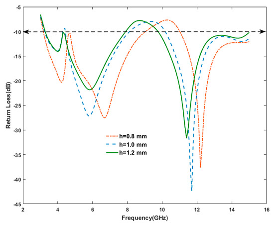
Figure 5.
Study of variation on substrate height of textile antenna on the basis of return loss plot.
4. Discussion
4.1. Comparative Analysis of Antenna I, Antenna II and the Anticipated Antenna
Figure 6 shows that in Antenna I, an impedance bandwidth of 60.19% was achieved in the first band from 3.6–6.7 GHz frequency, and 25.88% in the second band from 11.1–14.4 GHz frequency. In contrast, in Antenna II, the impedance bandwidths were 41.02% (3.1–4.7 GHz), 32.55% (9–12.5 GHz) and 9.25% (13.4–14.7 GHz); in the proposed structure impedance bandwidths of 24% (3.3–4.2 GHz), 58.26% (4.5–8.2 GHz) and 38.09% (10.2–15 GHz) were achieved, respectively. Looking at the comparative study of these three graphs, it seems that the proposed antenna gave a better result in terms of impedance-matching.
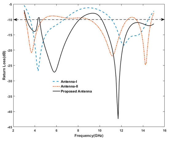
Figure 6.
Comparison of simulated return loss of Antenna I, Antenna II and the proposed antenna.
4.2. Experimental Return Loss of the Anticipated Antenna
A fabricated textile antenna was effectively designed and tested for the desired performance. The simulated results were obtained by a finite element method solver (HFSS) and CST for electromagnetic structures and practically validated by vector network analyzer. Figure 7 shows the front view and back view of fabricated textile antenna, respectively.
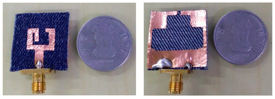
Figure 7.
Fabricated textile antenna front and back view.
Figure 8 shows the complete testing environment of the textile antenna through VNA Anritsu MS2038C inside the anechoic chamber under different situations.
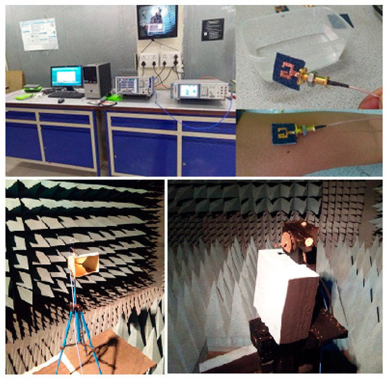
Figure 8.
Testing environment of the proposed antenna.
Figure 9 depicts that the measured impedance bandwidth of 23.37% (3.4–4.3 GHz), 56.48% (4.7–8.4 GHz) and 31.14% (10.3–14.1 GHz) frequency bands were observed, respectively. During the simulation in HFSS, the impedance bandwidth of 24% (3.3–4.2 GHz), 58.26% (4.5–8.2 GHz) and 38.09% (10.2–15 GHz) was obtained, whereas during CST simulation some smaller variations were observed, which appears in Figure 9. The microstrip feed width of the patch was optimized so that it presents triple band operation to allow use in WLAN, C band and X/Ku band applications.
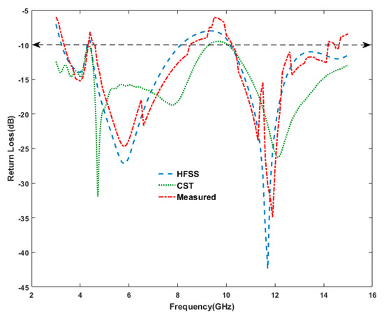
Figure 9.
Simulated and measured return loss performance.
4.3. Axial Ratio Performance
The projected antenna is additionally applicable as a circularly polarized antenna, which differentiates the textile antenna than the conventional antenna. Figure 10 presents the simulated axial ratio bandwidth (ARBW) observed as 8.16% (4.7–5.1 GHz), 6.55% (5.9–6.3 GHz) and 11.38% (11.6–13 GHz), respectively whereas the ARBW measured were 10.10% (4.7–5.2 GHz), 4.95% (5.9–6.2 GHz) and 10.44% (11.8–13.1 GHz), respectively. In comparisons of these results, smaller deviations were obtained between simulation and measurements.
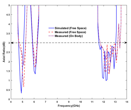
Figure 10.
Axial ratio performance of the proposed antenna.
4.4. Analysis of Experimental Gain
The measured and simulated gain of antenna is shown in Figure 11. It was clear that the peak measured gain in free space was 4.85 dBi, whereas the peak measured gain on the body was achieved 3.6 dBi at 4.1 GHz frequency. The gain varied with an increase of frequency, which is shown in Figure 11. To build the connection between network analyzer and prototype, a SMA connector was needed. The performance of wearable antenna changes due to losses occurred in SMA connector. Apart from this, it is being clear from this graph that the gain reduced due to human biologic tissue properties whenever the antenna was attached to the human body. After the analysis of the result, a small variation was found between simulated and measured gain (Figure 11).
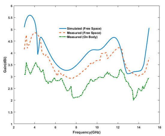
Figure 11.
Simulated and measured gain performance.
The essential values are listed in Table 2.
Table 2.
Gain performance at different frequencies.
4.5. Description of Radiation Pattern
Figure 12 depicts the measured radiation characteristics of the textile antenna in free space and on body, including co-polarization and cross-polarization at 5.2 GHz, 6 GHz and 12.2 GHz frequencies. The principal planes, E plane (y-z) and H plane (x-z) are used to show the effect of co and cross polarization. From Figure 12, it can be seen that the cross-polarization values were 10 to 20 dB less than the co-polarized values, which confirms that the antenna radiated in the desired direction. Some variations were obtained between free space and on body measurements due to the lossy characteristics of human body biologic tissues. Figure 12a shows the approximately omni-directional pattern during co-polarization in both the planes at 5.2 GHz frequency.
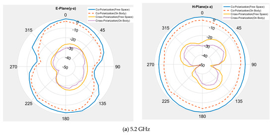
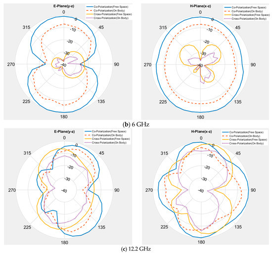
Figure 12.
Experimental radiation pattern at (a) 5.2 GHz, (b) 6 GHz, and (c) 12.2 GHz frequencies.
Similarly, at 6 GHz frequency, the shape of E-plane pattern changed with increasing frequency, whereas in the H-plane, the pattern was omni directional in co-polarization. Moving towards other higher frequencies, at 12.2 GHz, the radiation patterns changed during co and cross-polarization. The on-body performance was affected by the lossy nature of human body biologic tissues, which have a capability to absorb the electromagnetic waves.
4.6. Determination of Surface Current Distribution
To validate the circular polarization, the simulated current distributions at 12.2 GHz frequency using the HFSS simulator at distinct time periods are given in Figure 13. At time t = 0, the surface currents flowed along the direction of phi = 0°, whereas the direction of the surface currents changed in the upward direction at t = T/4 in the direction of phi = 90°. Further, the direction of the vector currents changed to phi = 180° and phi = 270° at time t = T/2 and 3 T/4, respectively. The surface vector current graph shows that the directions of current vector at t = T/2 and 3 T/4 were just reverse to the current vector at t = 0 and t = T/4, respectively. Due to rotation of surface current on electric dipole in clockwise direction also confirmed left-hand circular polarization (LHCP) action of the antenna.
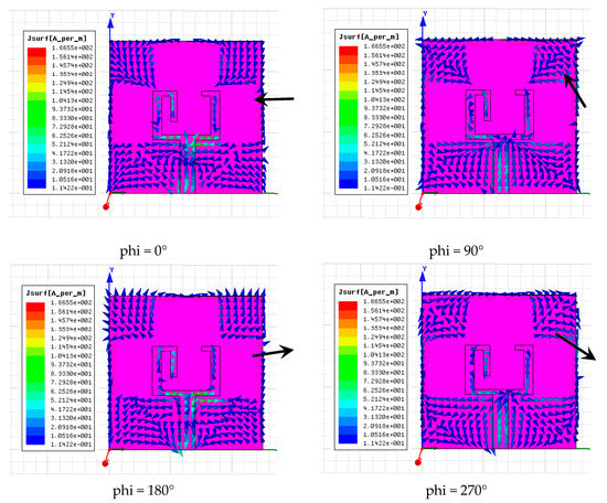
Figure 13.
Simulated surface current distribution at 12.2 GHz.
4.7. Analysis of Specific Absorption Rate
A SAR simulation of wearable antenna was carried out using HFSS simulator. To find the maximum value of SAR, the antenna was positioned on the skin layer of the human model cubic tissue. Simulations for 5.2 GHz and 5.5 GHz central frequency in reference to various input source powers starting from 25 mW up to 250 mW were carried out. To calculate the SAR value, the following formulae was used:
where
- σ is the conductivity in S/m
- E is electric field in V/m
- is the mass density in kg/m3
Human tissues also affect the performance of the antenna when it is attached to the human body. The electrical specification of human body tissues are listed in Table 3.
Table 3.
Specification of human body tissues.
Figure 14 represents the 3-D cross-sectional human body model to test the effect of SAR of the textile antenna. The following model includes skin layer, fat layer and muscle layer with their electrical properties.
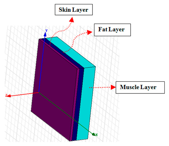
Figure 14.
Customized 3-D human body model layer.
By using the above human body model, SAR (specific absorption rate) was simulated on HFSS and a simulated peak value of a 10 g averaged SAR at 5.2 GHz and 5.5 GHz on various input source power, as presented in Table 4. By increasing the source power, the energy absorbed in the tissue increased significantly. Table 4 shows the values of SAR on different source power inputs.
Table 4.
SAR values for different source power.
By considering the above Table 4 in terms of user safety concerns, this value for the antenna should not be more than 100 mW. Based on European Standard (IEC) guidelines, the maximum values of SAR should be less than 2 (W/kg) for an average mass of 10 g. The antenna was simulated by placing it with the human model and in the result, it was found that its SAR value is inside the safer value as seen in Figure 15.
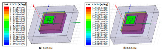
Figure 15.
Simulated specific absorption rate (SAR) pattern at 5.2 GHz and 5.5 GHz.
4.8. Performance of Antenna on Human Body
When any antenna applicable for wearable application is integrated with human body, it is mandatory to show the effect of antenna on human body. As we know, human body biologic tissue acts as a lossy components, which absorbs the electromagnetic components in it. As a result, the antenna return loss parameter degrades and the antenna functioning is affected. A wearable antenna must also work properly in all kinds of situations like bending and on-body moisture. Flat or conventional antennas do not fulfill these kinds of functionalities. Figure 16 shows the return loss vs. frequency plot under various investigations. In free-space condition, we achieved the measured S11 performances at three frequency bands (3.4–4.3 GHz, 4.7–8.4 GHz and 10.3–14.1 GHz), whereas this antenna is integrated with upper part of human arm, the S11 performance gets reduced due to lossy nature of body tissues (skin, fat and muscle). The total impedance bandwidth in free space measurement was 110.99% and whenever antenna was attached with human arm, it showed about 91.28%. However, in wet or antenna dipped in water, the impedance bandwidth was observed to be about 42.14%. As shown from the plot, a larger variation in wet condition was obtained; this is due to the scattering nature of the electromagnetic waves, interaction with water molecules.
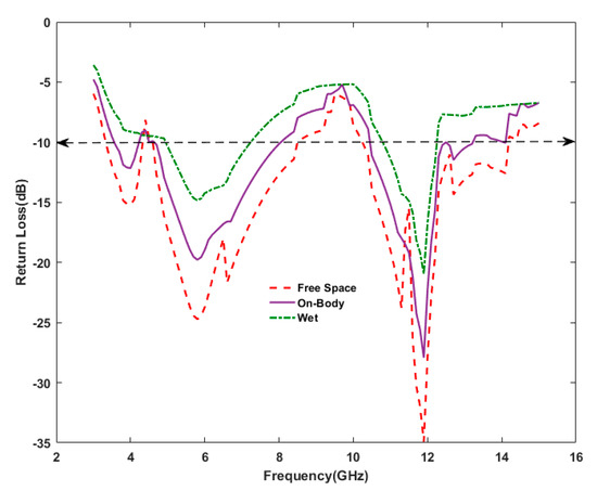
Figure 16.
Measured performance of antenna in different conditions.
A comparison of the performance of several existing and the proposed antennas is presented in Table 5. In comparisons with listed antennas, the proposed antenna provides size reduction, large impedance bandwidth and ARBW (axial ratio bandwidth) and low value of SAR for user safety.
Table 5.
Comparison of various existing antennas with anticipated antenna.
The results provided by the authors [18,19,20,21], the proposed antenna differentiate itself in terms of ARBW, safer SAR limit and better gain, respectively.
The peculiar characteristics of the anticipated antenna are described as follows:
- The proposed investigation offers an antenna flexible for WBAN application;
- This antenna requires less than about 100 mW of power to energize the radiator patch and minimize the radiation;
- This textile-based antenna offers impedance bandwidth of 110.99% under C band, X/Ku band (partially). It also offers ARBW (axial ratio bandwidth) of 25.49%, which has an additional advantage of this antenna to reduce the losses;
- This antenna offers safer SAR limit to protect the human body from undesired radiation.
5. Conclusions
A proposed compact, triple-band and wearable antenna was designed and tested successfully. Copper tape was utilized to fabricate the radiating patch and defective ground section of an anticipated textile antenna, with a thickness of 0.35 mm. The triple-band impedance bandwidth of 23.37% (3.4–4.3 GHz), 56.48% (4.7–8.4 GHz) and 31.14% (10.3–14.1 GHz) frequency bands were observed, respectively. The proposed textile antenna is also applicable for circular polarization with ARBW (axial ratio bandwidth) of 10.10% (4.7–5.2 GHz), 4.95% (5.9–6.2 GHz) and 10.44% (11.8–13.1 GHz) frequency bands. The measurement of results was very much closer to the simulation results and shows that a good justification is achieved between simulated and measured values. This textile antenna is applicable for circularly polarized triple band with good radiation performance, gain and acceptable SAR values.
Author Contributions
All authors have designed the study, developed the methodology, performed the analysis, and written the manuscript. All authors have read and agreed to the published version of the manuscript.
Funding
This research received no external funding.
Acknowledgments
The authors wish to acknowledge for providing measurement facility at antenna Laboratory, GBPEC, New Delhi, India.
Conflicts of Interest
The authors declare no conflict of interest.
References
- Khaleel, H. Innovation in Wearable and Flexible Antennas; WIT: Southampton, UK, 2015. [Google Scholar]
- Silva, P.F., Jr.; Freire, R.C.S.; Serreset, A.J.R.; Silva, P.D.F.; Silva, J.C. Wearable textile bioinspired antenna for 2G, 3G, and 4G systems. Microw. Opt. Technol. Lett. 2016, 58, 2818–2823. [Google Scholar] [CrossRef]
- Pinapati, S.P.; Kaufmann, T.; Ranasinghe, D.C.; Fumeaux, C. Wearable dual-band stripline-fed half-mode substrate-integrated cavity antenna. Electron. Lett. 2016, 52, 424–426. [Google Scholar] [CrossRef]
- Sundarsingh, E.F.; Velan, S.; Kanagasabai, M.; Sarma, A.K.; Raviteja, C.; Alsath, M.G.N. Polygon-Shaped Slotted Dual-Band Antenna for Wearable Applications. IEEE Antennas Wirel. Propag. Lett. 2014, 13, 611–614. [Google Scholar] [CrossRef]
- Gao, G.P.; Hu, B.; Tian, X.L.; Zhao, Q.L.; Zhang, B.T. Experimental study of a wearable aperture-coupled patch antenna for wireless body area network. Microw. Opt. Technol. Lett. 2017, 59, 761–766. [Google Scholar] [CrossRef]
- Singh, N.; Singh, A.K.; Singh, V.K. Design and performance of wearable ultra wide band textile antenna for medical applications. Microw. Opt. Technol. Lett. 2015, 57, 1553–1557. [Google Scholar] [CrossRef]
- Hu, B.; Gao, G.P.; He, L.L.; Cong, X.D.; Zhao, J.N. Bending and on-arm effects on a wearable antenna for 2.45 GHz body area network. Antennas Wirel. Propag. IEEE Lett. 2016, 15, 378–381. [Google Scholar] [CrossRef]
- Yadav, A.; Kumar Singh, V.; Kumar Bhoi, A.; Marques, G.; Garcia-Zapirain, B.; de la Torre Díez, I. Wireless Body Area Networks: UWB Wearable Textile Antenna for Telemedicine and Mobile Health Systems. Micromachines 2020, 11, 558. [Google Scholar] [CrossRef] [PubMed]
- Jiang, Z.H.; Brocker, D.E.; Sieber, P.E.; Werner, D.H. A compact, low-profile metasurface enabled antenna for wearable medical body-area network devices. IEEE Trans. Antennas Propag. 2014, 62, 4020–4030. [Google Scholar] [CrossRef]
- Yu, X.J.; Tang, Q.; Liang, M.; Xin, H. Study of power efficiency of non-foster impedance matching for electrically small antenna. In Proceedings of the 2014 USNC-URSI Radio Science Meeting, Memphis, TN, USA, 6–11 July 2014. [Google Scholar]
- Mourad, M.; Essaaidi, M. A dual ultra wide band slotted antenna for C and X-band application. Prog. Electromagn. Res. Lett. 2014, 47, 91–96. [Google Scholar]
- Yadav, A.; Singh, V.K.; Mohan, H. Design of a U-shaped circularly polarized wearable antenna with DGS on a fabric substrate for WLAN and C-band applications. J. Comput. Electron. 2019, 18, 1103–1109. [Google Scholar] [CrossRef]
- Ansari, J.A.; Verma, S.; Verma, M.K.; Agrawal, N. Novel Wide Band Microstrip-Line-Fed Antenna with Defected Ground for CP Operation. Prog. Electromagn. Res. C 2015, 58, 169–181. [Google Scholar] [CrossRef]
- Jain, A.K.; Kanaujia, B.K.; Dwari, S.; Pandey, G.P.; Singh, D.K. Wideband circularly polarized magnetoelectric dipole antenna with I-slot for C-band applications. J. Comput. Electron. 2019, 18, 660–670. [Google Scholar] [CrossRef]
- Wu, C.-M.; Syu, J.-W.; Liu, W.-C. Dual-band slotted patch antenna with defective ground forWLAN/WiMAX applications. Prog. Electromagn. Res. Lett. 2015, 53, 1–6. [Google Scholar] [CrossRef]
- Agneessens, S.; Rogier, H. Compact Half Diamond Dual-Band Textile HMSIW On-Body Antenna. IEEE Trans. Antennas Propag. 2014, 62, 2374–2381. [Google Scholar] [CrossRef]
- Azeez, H.I.; Yang, H.C.; Chen, W.S. Wearable Triband E-Shaped Dipole Antenna with Low SAR for IoT Applications. Electronics 2019, 8, 665. [Google Scholar] [CrossRef]
- Singh, V.K.; Dhupkariya, S.; Bangari, N. Wearable Ultra Wide Dual Band Flexible Textile Antenna for WiMax/WLAN Application. Int. J. Wirel. Pers. Commun. 2017, 95, 1075–1086. [Google Scholar] [CrossRef]
- Chaihongsa, W.; Phongcharoenpanich, C. Performance of Textile Antenna using Two Layers of Strip Line and Round-off Circular Patch. In Proceedings of the IEEE Conference on Antenna Measurements & Applications (CAMA), Chiang Mai, Thailand, 30 November–2 December 2015; pp. 1–3. [Google Scholar]
- Mersani, A.; Osman, L. Design of Dual-band Textile Antenna for 2.45/5.8-GHz Wireless Applications. In Proceedings of the IEEE International Conference on Multimedia Computing and Systems (ICMCS), Marrakech, Morocco, 29 September–1 October 2016; pp. 397–399. [Google Scholar]
- Verma, M.K.; Kanaujia, B.K.; Saini, J.P.; Saini, P. A novel circularly polarized gap-coupled wideband antenna with DGS for X/Ku-band applications. Electromagnetics 2018, 39, 186–197. [Google Scholar] [CrossRef]
- Sankaralingam, S.; Gupta, B. Determination of Dielectric Constant of Fabric Materials and Their Use as Substrates for Design and Development of Antennas for Wearable Applications. IEEE Trans. Instrum. Meas. 2010, 59, 3122–3130. [Google Scholar] [CrossRef]


© 2020 by the authors. Licensee MDPI, Basel, Switzerland. This article is an open access article distributed under the terms and conditions of the Creative Commons Attribution (CC BY) license (http://creativecommons.org/licenses/by/4.0/).