1. Introduction
In the scientific research and exploitation practice of induction motor (IM) drives, it is necessary to find reliable solutions for diagnostic systems, which are expected to meet more and more difficult requirements. At the same time, there is a move away from highly specialized and expensive solutions to low-budget systems based on measuring cards, cheap microprocessors and widely available software environments [
1,
2,
3,
4]. In such flexible diagnostic systems, it is possible to extend functionality relatively quickly by adding extra software modules, in which different signal processing methods are used.
Currently, in the fault monitoring and diagnostics of IM drives, the dominant approach is based on the analysis of signals which can be measured directly on a given object, i.e., mechanical vibrations [
5,
6,
7,
8,
9,
10,
11] and stator current [
6,
7,
12,
13,
14,
15]. So far, diagnostics has been based on the analysis methods of easily measurable signals using the knowledge and experience of human experts, who make interpretations of on-going data obtained from the measurements and analyses conducted by measurement systems. Unfortunately, this approach has one weak point, namely the human expert, who can make a mistake and whose experience can hardly be automated. This is why, apart from improving the methods of diagnostic signals analysis, it is necessary to find some ways of objectifying the process of fault detection and the assessment of fault level. This can be obtained by the use of artificial intelligence methods and techniques, which are nowadays also popular in the diagnostics of IM drives [
16,
17]. Different structures of neural networks (NNs) have been used in the detection of electric motor faults, e.g., multi-layer perceptron (MLP) [
5,
8,
10,
18,
19,
20,
21], general regression neural network [
21,
22], self-organizing networks [
23,
24], adaptive neuro-fuzzy inference system (neuro-fuzzy inference) [
25], and the following deep neural network (DNN) models: deep Boltzmann machines, deep belief networks and stacked auto-encoders [
26], convolutional neural network [
27,
28,
29,
30] and one-dimensional convolutional neural networks (CNN) [
3,
31].
MLP networks are the most frequently used in the field of NN applications for detecting rolling bearing damage. An example can be found in [
5], which presents MLP structures based on a discrete wavelet transformation of the vibration acceleration signal. Simple structures of neural detectors with one hidden layer were used, containing one or three output neurons. The developed neural detectors were characterized by a very high average efficiency of over 97%.
An MLP network based on five statistical features calculated from the wavelet analysis of mechanical vibrations is also presented in [
8]. The authors analyzed a single-layer network with 18 neurons in the hidden layer. The results obtained for Daubechies wavelets from “db1” to “db45” were analyzed. The maximum efficiency obtained was approximately 95%.
In Reference [
10], the authors developed three-layer NNs with 10, 15, 20, 25, 30 and 35 neurons in the hidden layer, respectively. In addition to the two characteristic amplitudes of damage frequencies, the amplitude of the rotational frequency, the Kurtosis factor of the vibration waveform, and the maximum and average values of the vibration signals are given for the inputs of the NNs. At the output, only information about the technical condition of the tested bearing was obtained. The NN did not inform us as to which structural element of the bearing was damaged. Despite the much larger number of neurons in the hidden layer and the seemingly simpler task (determining whether the bearing is damaged or not), the presented neural detectors were characterized by an average detection efficiency of approximately 86–96%, depending on the structure.
In Reference [
18], the developed neural detectors were based on measurement data from three databases. Depending on the database used, the neural detector had four, six or three neurons in the output layer and five neurons in the hidden layer. The statistical features calculated in the time domain were given as the inputs to the neural networks. The authors obtained an effectiveness above 95%.
The paper [
19] presents MLP neural detectors containing one or two hidden layers and two neurons in the output layer. The developed NNs indicated no damage to the bearing and no damage to the inner or outer race. The authors used characteristic features derived from the time and frequency domains as symptoms.
In the paper [
20], MLP-based neural detectors whose task was to identify seven technical conditions of an IM, including an undamaged motor with a damaged bearing, a damaged rotor bar and a different number of shorted stator turns, were presented. The NNs contained seven neurons in the output layer. Each neuron took a value of 0 or 1 depending on the technical condition of the machine. The symptoms characterizing the failures were nine statistical features calculated in the time domain from the stator current signal. In the work, NNs containing from 2 to 16 neurons in the hidden layer were checked. The neural detectors proposed by the authors were characterized by the highest efficiency at the level of approximately 91%.
The possibility of using the general regression neural network (GRNN) to detect damage to the rolling bearings and planetary gearbox was presented in [
22]. In this case, the measurement data from the bearing testing came from the Mechanical Failures Prevention Group. The authors analyzed the effectiveness of detecting an undamaged bearing with a damaged inner raceway. An accuracy of 90% was achieved for the network without signal pre-processing, while the pre-processing of the signal allowed the detection accuracy to be increased to 96%. The proposed method of initial signal pre-processing consists of dividing the features of each fault pattern by its fault characteristic frequency value.
The work [
24] may serve as an example of using the Self-Organizing Map (SOM) to classify damages to rolling bearings. The authors used measurement data from the Bearing Data Center of Case Western Reserve University. They prepared a total of 70 features for teaching the network, such as statistical features, frequency domain features, autoregressive model coefficients, wavelet packet decomposition analysis and empirical mode decomposition entropy energy. Two techniques were used to select the optimal features (extended relief and min redundancy max relevance (mRMR) algorithms), which allowed them to obtain as much as 100% effectiveness for 33 features. The proposed method is 100% effective; however, the NNs networks described in this paper are very large and complicated as regards their real implementation.
In turn, in [
25], an adaptive neuro-fuzzy inference system was used to detect damage to the rolling bearings. The authors developed a structure that translated the input data into three different triangular membership functions, which corresponded to the three technical conditions of the bearing (good, damaged and bad). The discussed structure consisted of 27 rules. The authors achieved an effectiveness of 99%, which unfortunately has not been verified on real object.
In recent years, DNNs of different types have also been used to diagnose rolling bearings. The CNN proposed in [
3] was applied to determine whether the tested IM is operational, and whether it has damaged bearings or a damaged rotor cage. Vibrations were used as the diagnostic signal. The diagnostic system developed by the authors detected an undamaged condition and rotor damage with an efficiency of 98%, while it detected bearing damage at 100% effectiveness.
In Reference [
26], the authors presented three DNNs: Deep Boltzmann Machines, Deep Belief Networks and Stacked Auto-Encoders. In addition, they conducted research based on four pre-processing schemes. The obtained detection efficiencies ranged from approximately 15% to 99%, depending on the scheme used.
In turn, Reference [
27] presents an example of a CNNs used to detect damage to rolling bearings. The signals for NN testing were based on data obtained from the Electrical Engineering Laboratory of Case Western Reserve University Bearing Fault Database, and not on the measurement signals obtained on the test stand by the authors. Unfortunately, in this case, it was also not possible to check how the CNN works in the online mode and how it reacts to other damages occurring in the induction motor. In Reference [
28], the CNN was also proposed for rolling bearing diagnostics, and the authors reported 100% effectiveness in simulation studies. However, this effectiveness during verification with measurement signals from the same database as in [
27] was only 88%.
In Reference [
30], the authors proposed a CNN to detect damage to rolling bearings based on the wavelet analysis of the vibration acceleration signal obtained from the above-mentioned database and from the BaoSteel MRO Management System. The accuracy of the proposed method was over 97%, and it depended on the source of the measurement data set.
In Reference [
31], the authors used a one-dimensional CNN to detect damage to rolling bearings. The recorded vibration signals came from the NASA Prognostic Data Repository. The paper compares the effectiveness of the proposed CNN with MLP, Radial Basis Function Networks (RBFN) and Support Vector Machines (SVM). The obtained efficiencies were at the level of approximately 94–97%, depending on the used NN. In none of the above-mentioned research was the operation of DNN-based detectors tested in on-line operation on research stands.
The detectors presented in the literature differ in terms of their structure, symptoms and learning method, and thus their effectiveness. In the case of all DNNS, their structure is very complex, and the learning process is time-consuming and complicated, but if the input signals are properly prepared, very good diagnostic results can be obtained. However, it is difficult to compare them to MLP networks as they are completely different structures. In addition, DNNs require incomparably greater computing power and processor memory in relation to MLPs, in particular for the very simple structures proposed in this article. The conducted analysis of the literature also shows, in the case of testing neural detectors in on-line work, their response to other damages occurring in electric drive.
The neural detectors proposed in this paper are characterized by a very simple structure (they contain a maximum of five neurons in one hidden layer), and they indicate which structural element of the bearing is damaged and have a relatively high efficiency. Moreover, tests of the sensitivity of the developed detectors to other damages occurring in IMs were also presented.
Based on the literature analysis, it can be concluded that automated diagnostic systems for IM rolling bearings using artificial intelligence, including NNs, are rarely presented in the available literature. Thus, the aim of the work is to present a cheap measurement and diagnostic system that can work in off-line and on-line modes, based on a vibration acceleration sensor and software implemented in the LabView environment. The proposed application is based on three basic analyses of mechanical vibrations: the first one assesses the vibration level based on the ISO 10816-1: 1998 standard, the second enables the spectral analysis of mechanical vibration acceleration, and the third allows the analysis of the vibration acceleration envelope. The application is equipped with two independently operating MLP networks, with a very simple structure, which are to help the diagnostician make the right decision. The developed application is designed to conduct diagnostics of low and medium power IMs in the steady-state operating conditions of the drive. The correctness of the system’s operation has been verified via numerous experimental tests on an IM with not only a damaged bearing, but also with other types of damage, such as inter-turn short circuit of the stator winding, damage to rotor bars and misalignment. It was shown that the proposed NN-based low-cost diagnostic system correctly distinguishes bearing failures from other types of motor failures.
The article consists of six sections. After the Introduction, in the second section the applied method of the rolling bearing fault detection is briefly described. Next, the neural fault detectors based on MLP network and vibration signal analysis are presented, and their efficiency is discussed. In the fourth section, the concept of a computer system for on-line monitoring and diagnostics of the IM rolling bearings is described. The experimental results obtained with the use of the developed low-cost diagnostic system are demonstrated in the following section. The article is finished with a short summary.
2. Detection of Rolling Bearings Faults
Rolling bearing damages are the most common damages in rotating machines. Depending on the type and size of the machine, the percentage share of rolling bearings faults in the total number of machine faults is in the range of 40–90% [
6,
7,
32]. The costs of replacing rolling bearings are small in comparison with the costs of motor overhaul. This is why diagnostics of the technical condition of a bearing node is so important from the technical and economical points of view.
In recent years, there have been a lot of new and efficient methods for monitoring the condition of the IM rolling bearings [
7]. Positive test results motivate one to undertake the practical implementation of a computer system used for monitoring the condition of IM rolling bearings, operating on-line. Such an approach allows one to complete classical methods of the monitoring and diagnostics of IM drives with new tools facilitating diagnostic decisions.
Bearing faults can be divided into distributed and local faults [
12]. Distributed faults refer to the whole bearing area, and they are hard to characterize with any typical frequency. Local faults usually refer to single-point damages, and with regard to the faulty element they can be divided into:
The failure symptoms assessment of the construction elements of bearings is done using vibration spectra or specialized analyses, and is based on the assumption that single-point faults of bearing element surfaces generate vibrations with characteristic frequencies. These frequencies can be determined on the basis of the knowledge of bearing construction parameters according to the relationships given below [
5,
7,
9,
10,
11,
12,
13,
14,
15,
19,
22,
24,
31]:
where
Db is the ball diameter,
Dc is the cage diameter,
ϑ is the contact angle between the balls and the cage,
Nb is the number of balls in the bearing,
fr is the rotor mechanical frequency,
fc is the cage fault frequency,
fir is the inner race fault frequency,
for is the outer race fault frequency and
fb is the ball fault frequency.
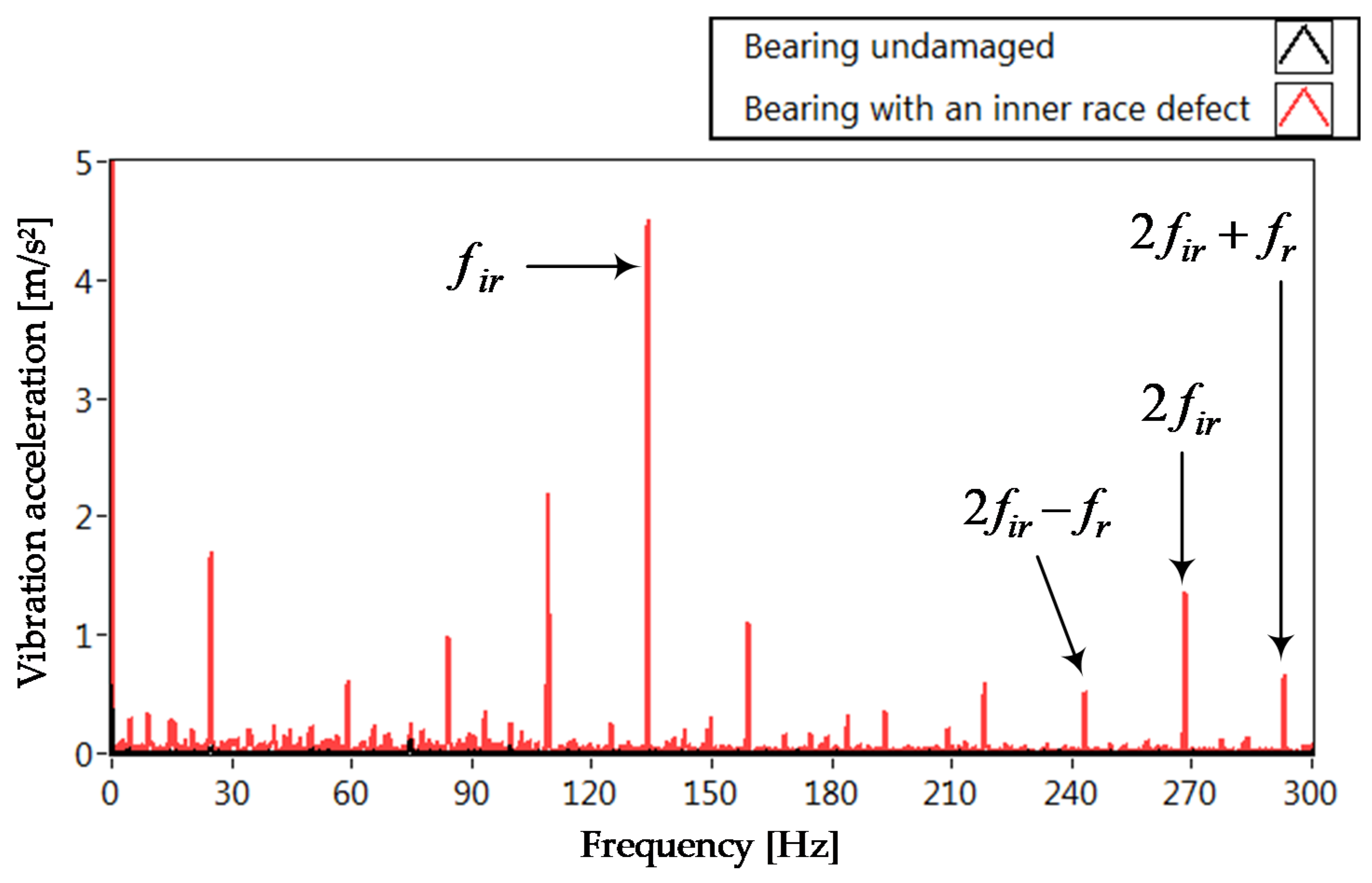
In the spectra of vibration acceleration and its envelopes, there are not only the frequencies described by relationships (1)–(4), but also their subsequent multiplicities and components displaced by the current value of the rotational frequency ±fr.
The above-mentioned characteristic harmonics are presented in
Figure 1 as a sample of the Fast Fourier Transform (FFT) spectra of the vibration acceleration signal for a motor with undamaged bearings and a damaged inner race, operating without any load.
Figure 2 shows the results obtained for the FFT analysis of the vibration acceleration envelope.
The spectrum of the vibration acceleration envelope (
Figure 2), in comparison with the FFT analysis of the vibration acceleration (
Figure 1), is characterized by a clear increase in the amplitudes of the basic frequency characteristic for bearing damage (
fir, 2
fir, …). Therefore, these were selected primarily for the training of neural detectors. Moreover, the spectrum shows very clearly the components shifted by ±
fr in relation to the damage frequency, but their values in the FFT analysis of the vibration acceleration signal are very small (
Figure 1), and any disturbance or change in the drive’s operating conditions may disturb their value. This is one of the reasons why these harmonics were omitted while constructing neural detectors.
Summarizing, it can be said that preliminary tests for a low-power motor have shown that by using the spectral analysis of the vibration acceleration and the vibration acceleration envelope, it is possible to detect a damaged rolling bearing. The changes in the amplitudes of characteristic frequencies differ in level depending on the analyzed diagnostic signal. Nevertheless, these changes can be used for diagnostics, in particular for neural inference. In order to automate the diagnostic process,
Section 3 presents an analysis of the possibility of using neural detectors to detect damages to rolling bearings.
3. Neural Detector of Rolling Bearings
The neural architecture most frequently used in practical applications is multi-layer perceptron (MLP) [
5,
8,
18,
19,
21]. Here, representations of every element of an input vector are analyzed by numerous neurons simultaneously. The MLP network structure includes neurons grouped into layers, including input and output layer, and also hidden layers which do not have any direct connection with external signals. In addition to this, there are no connections between neurons in the same layer.
In the presented research, the hyperbolic tangent activation functions were used in the hidden layer, while the output neurons were linear. The choice of the MLP network with the linear activation function in the output layer was dictated by the overriding goal of the diagnostic system’s development, which was its simplicity and minimized number of calculations, due to the price of the target microprocessor system. The values of weight connection coefficients were selected using the Levenberg–Marquardt algorithm as a training algorithm [
19,
33].
The NN input vectors should consist of fault symptoms that respond only to a specific damage to the bearing. The change in these symptoms should be large enough that possible noise and measurement disturbances do not have a significant impact on its level. Moreover, the selected symptom should not be a multiple of the symptom characteristic of another failure. For the bearing under test, some characteristic failure frequencies are approximately equal to each other, e.g., 5
fb − 2
fr ≈ 3
for −
fr ≈ 2
fir −
fr, 5
fb ≈ 3
for + fr ≈ 2
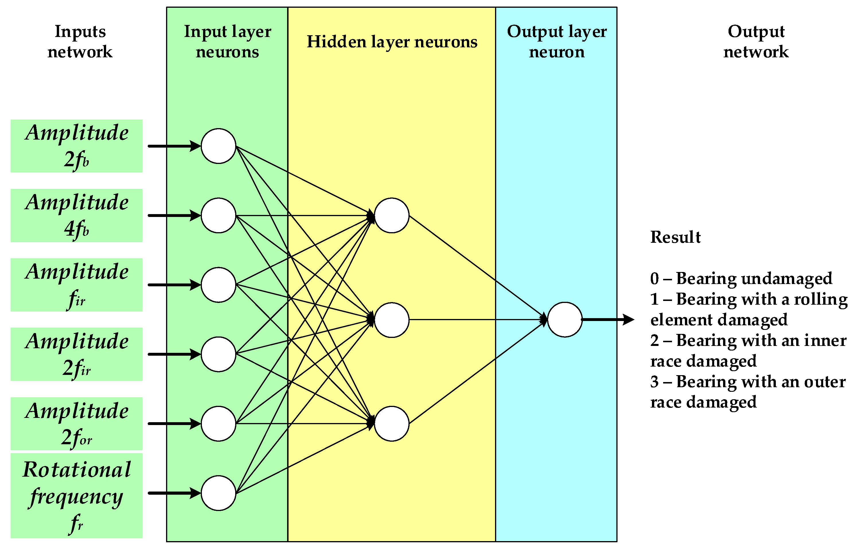
fir + fr. Moreover, those symptoms were selected which reacted to the same failures in both the spectral analysis of vibration acceleration and in the FFT analysis of the signal envelope. A preliminary analysis of diagnostic symptoms showed that harmonics with frequencies 2
fb, 4
fb,
fir, 2
fir and 2
for respond best to different bearing damages, and therefore these symptoms were selected as input signals of NN (
Figure 3). Additionally, in order to take into account the variable speed and load torque, the input vector was extended by the rotational frequency
fr.The design of the neural detector was made in the Matlab–Simulink environment. The task of the neural detector was to detect the type of the damaged structural element of the bearing. The output layer consisted of only one output neuron. In the NN output information, 0 appeared for an undamaged bearing and 1 for a damaged ball, and 2 for a damaged inner race and 3 for a damaged outer race.
Data from two different measurement sets were selected to train the NNs, while they were tested with the third measurement set. Each set was composed of 10 measurements of a bearing which is undamaged, has one damaged ball, has a damaged inner race (two different failure cases) or has a damaged outer race (two different failure cases). The input vector used to train the NNs was composed of 120 elements, while the testing vector had 60 elements. The tests were conducted for the data obtained from the FFT analysis of vibration acceleration and the FFT analysis of the vibration acceleration envelope, using different numbers of neurons in the hidden layers of the designed NNs. Vibrations were measured using a uniaxial (axial direction of vibration) and a triaxial accelerometer (radial direction of vibration). The arrangement of accelerometers and the determination of the directions of mechanical vibration measurements are illustrated in
Figure 4.
The preliminary tests carried out were aimed at selecting the structure of the NN detector and testing the influence of the direction of vibration measurement. In the first stage, the effectiveness of detecting the type of rolling bearing damage was checked on the basis of data obtained from the FFT analysis of vibration acceleration.
Table 1 summarizes the effectiveness of different NNs after testing procedures. The average NN effectiveness was determined on the basis of 11 subsequent tests conducted for a given NN structure with randomly selected initial weights, trained on the basis of prepared learning vectors. Three simple NN structures were checked, with six inputs (like in
Figure 3) and with three, four and five neurons in the hidden layer, respectively. Studies have shown that the relatively simple (6-3-1) NN has an average efficiency (after 11 subsequent testing series) of 93.7% for the axial direction, and 95.9% for the radial direction, of the vibration measurement.
Similar tests were performed for the analysis of the envelope of vibration acceleration (
Table 2). In this case, the NN with three neurons in the hidden layer had an average detection efficiency of 94.4% for the axial direction and 97% for the radial direction of the vibration measurement, which is quite a good result.
We also checked how the detection would proceed in a situation wherein the vibration is measured in different directions. For this purpose, an attempt was made to train and test NNs from the data obtained simultaneously from the FFT and envelope analysis of vibration acceleration for various directions of vibration measurements. In the described situation, a learning vector was created, which consisted of two measurement series obtained from the FFT analysis of vibration acceleration for the uniaxial accelerometer (120 samples), and two measurement series from the FFT analysis of vibration acceleration for the triaxial accelerometer (radial direction) (120 samples) (240 samples in total). The testing vector consisted of the data from the third measurement series and contained 120 samples. The training and testing results with data obtained from the analysis of the vibration acceleration envelopes looked similar. In
Table 3, the results obtained from the testing of the different neural detector structures are presented.
Furthermore, in this case the average detection efficiency was very high (over 90%). Only for the structure (6-3-1) trained by the data obtained from FFT analysis of vibration acceleration was the average efficiency about 86%. The average value was underestimated by the low detection efficiency (55.8%) of the one tested NN.
Based on these preliminary research results, a simple structure of NN with three neurons in the hidden layer was taken into account for building the application. In further research, the axial direction of vibration measurement was adopted.
Figure 5 presents the test results of this simple neural detector (structure (6-3-1)) based on the information from the FFT analysis of vibration acceleration. The detector was tested with the data that were not used in the learning process. In the presented example, the obtained efficiency was about 98.3%. This efficiency defined the percentage share of correct responses in all responses.
4. The Concept of a Computer System for Monitoring and Diagnostics of Induction Motor Rolling Bearings
Figure 6 presents a structured flowchart depicting the concept of the computer-based system for monitoring IM rolling bearings. The concept of the developed diagnostic system is based on the following initial assumptions:
The system allows the user to monitor basic parameters of the tested machine on-line:
- –
time courses of mechanical vibration acceleration and vibration acceleration envelope;
- –
effective value of the measured signal.
The extraction of characteristics necessary to evaluate the condition of rolling bearings is conducted on the basis of mechanical vibration analyses. The basis analyses used in the presented diagnostic systems are:
- –
classical FFT analysis of mechanical vibration;
- –
vibration acceleration envelope analysis;
- –
analysis of machine condition under PN-ISO 10816-1:1998 standard.
The detection efficiency of the rolling bearings should be improved by the implemented neural network.
The diagnostic system should allow the user to create a database of diagnostic signals.
The application should allow for a repeated analysis of recorded diagnostic signals.
The system should allow the user to generate final reports on the conducted research.
The computer system of the monitoring and diagnostics of the condition of the IM rolling bearings was developed in the LabVIEW environment. The application may be used both on an industrial computer made by National Instruments and on a traditional PC or a laptop. Moreover, it is possible to register the measurement signal with any measurement card cooperating with LabVIEW software. The universality of the equipment is an undoubtable advantage of the presented system. This system, developed in the LabVIEW environment, has a modular structure. The current version of this application consists of four main elements:
motor database;
rolling bearings database;
machine monitoring—on-line (the main program of the application);
measurement data analysis—off-line.
Figure 7 presents the title page of the application with the possibility of choosing one of the above elements.
The first module allows one to look through the motor database using three methods: manufacturing number, serial number and the so called “motor after motor”. In addition to this, it allows one to add new motors to the existing database. The database includes the rated parameters of tested machines.
The second module offers an opportunity to look through the database of rolling bearings using two methods: manufacturing number and the so called “bearing after bearing”. Moreover, this part allows one to add new bearings to the existing database. The database includes the construction parameters of bearings and characteristic fault frequencies.
The third module is the main element of the application. It allows for continuous monitoring of the current condition of the tested machine, and the creation of a database of the registered signals in an automatic mode (automatic record cycle set up by a user) and a manual one. To start this module, it is necessary to enter appropriate introductory information into the first and the second module. For the purpose of a possibly automated assessment of the rolling bearing condition, the module is equipped with two neural detectors operating independently. The first one is based on the information obtained from the FFT analysis of vibration acceleration, and the other one is based on the FFT analysis of the vibration acceleration envelope. An additional advantage of this module is the possibility of generating detailed reports taking into account the information available in the third module.
The fourth module allows to one reproduce measurement signals recorded earlier. Similar to the previous modules, it is possible to generate a detailed report of the conducted tests.
5. Experimental Verification of the Computer Monitoring System of the Condition of Induction Motor Rolling Bearings
The experimental verification was conducted for the induction motor of 1.5kW. A DC machine was used for generating the load torque of the tested motor. The IM was equipped with ball bearings, 6205 2Z type, with the following artificially modeled defects: balls (pointwise damage of two balls), inner race (2cm-long surface damage) and external race (external race cut). The tests were done using an industrial computer NI PXI 8186 equipped with a measurement card NI USB 9234. The processing and detailed analyses of measurement data, including the selection of the characteristic symptoms of bearing defects, were conducted in the described computer monitoring system of the rolling bearings. The characteristic symptom is understood as the amplitudes of the bearing damage characteristic frequencies (Equations (1)–(4)), and their subsequent multiplicities and components displaced by the actual value of rotation frequency ±
fr, presented in
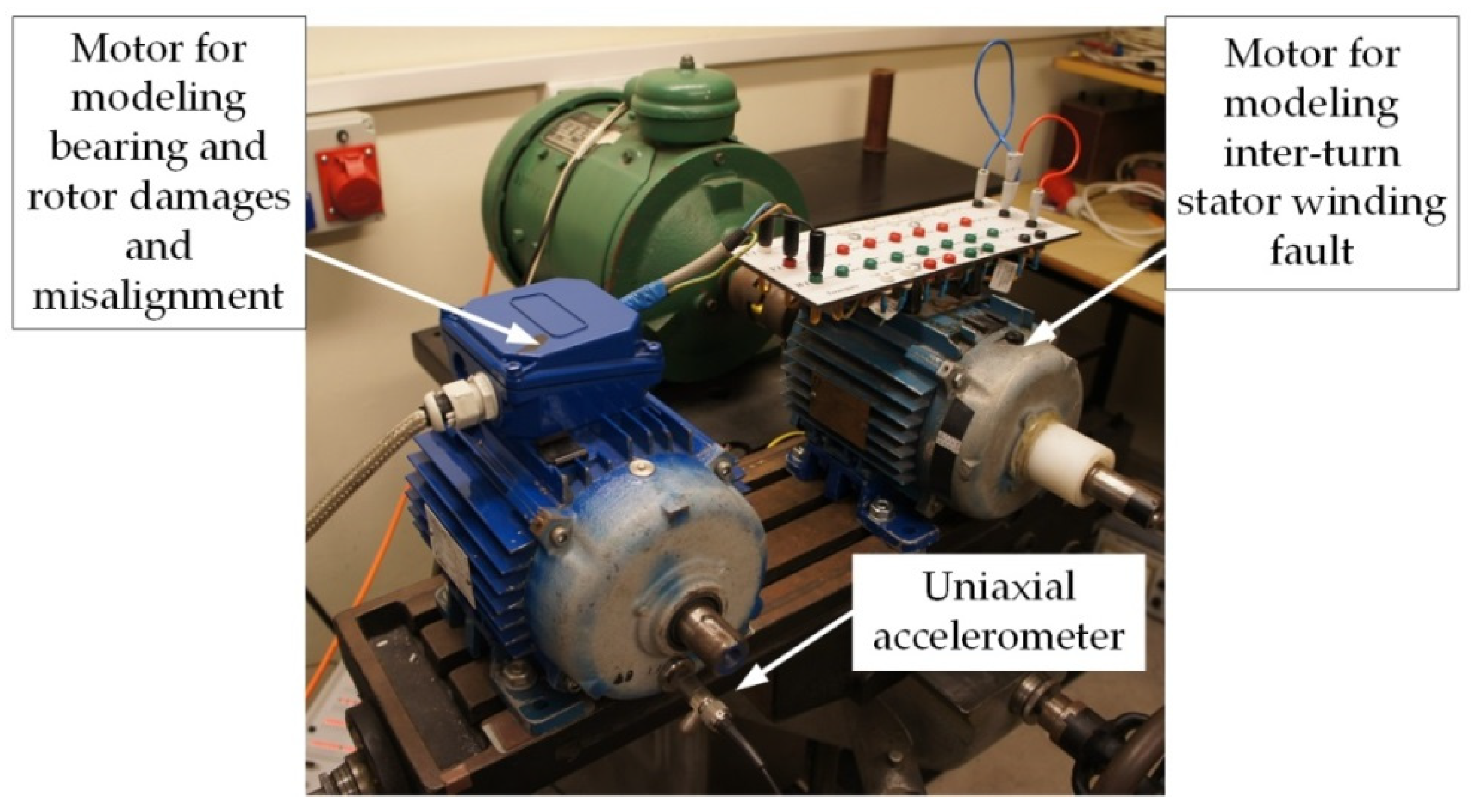
Section 2. The vibration measurements were conducted using the uniaxial accelerometer, 3185D type, made by DYTRAN (Dytran Instruments, Inc., 21592 Marilla Street Chatsworth, Los Angeles, CA 91311, USA) installed on the bearing cover, as shown in
Figure 8. Vibration acceleration was measured with 25.6 kS/s sampling. In
Figure 8, an additional IM of the same type and rated power is visible with specially prepared stator winding for modeling of the inter-turn short circuits. The tested rolling bearings were also mounted in this second IM under testing. The stator winding faults, as well as misalignment failures, were modeled additionally to prove that the developed neural detector-based system for rolling bearing faults monitoring and diagnostics is insensitive to other types of IM damage.
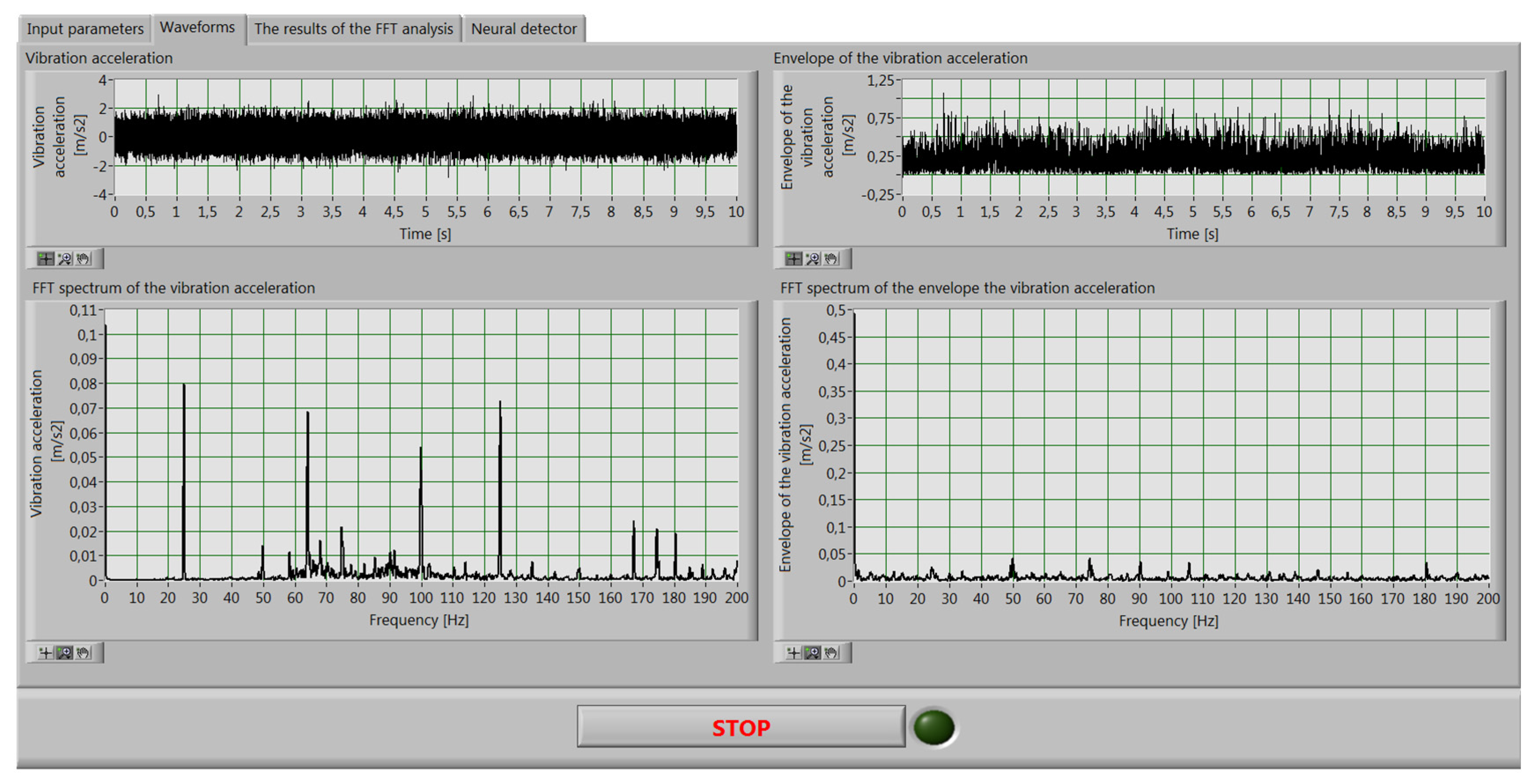
Figure 9 presents a sample screen from the computer monitoring system of the condition of the IM rolling bearings. The time courses of vibration acceleration and vibration acceleration envelope, as well as their FFT analyses, are demonstrated. In
Figure 10 a sample screen of the “Neural detector” page is shown. Transition between pages allows one to observe the on-line operation of the whole computer system.
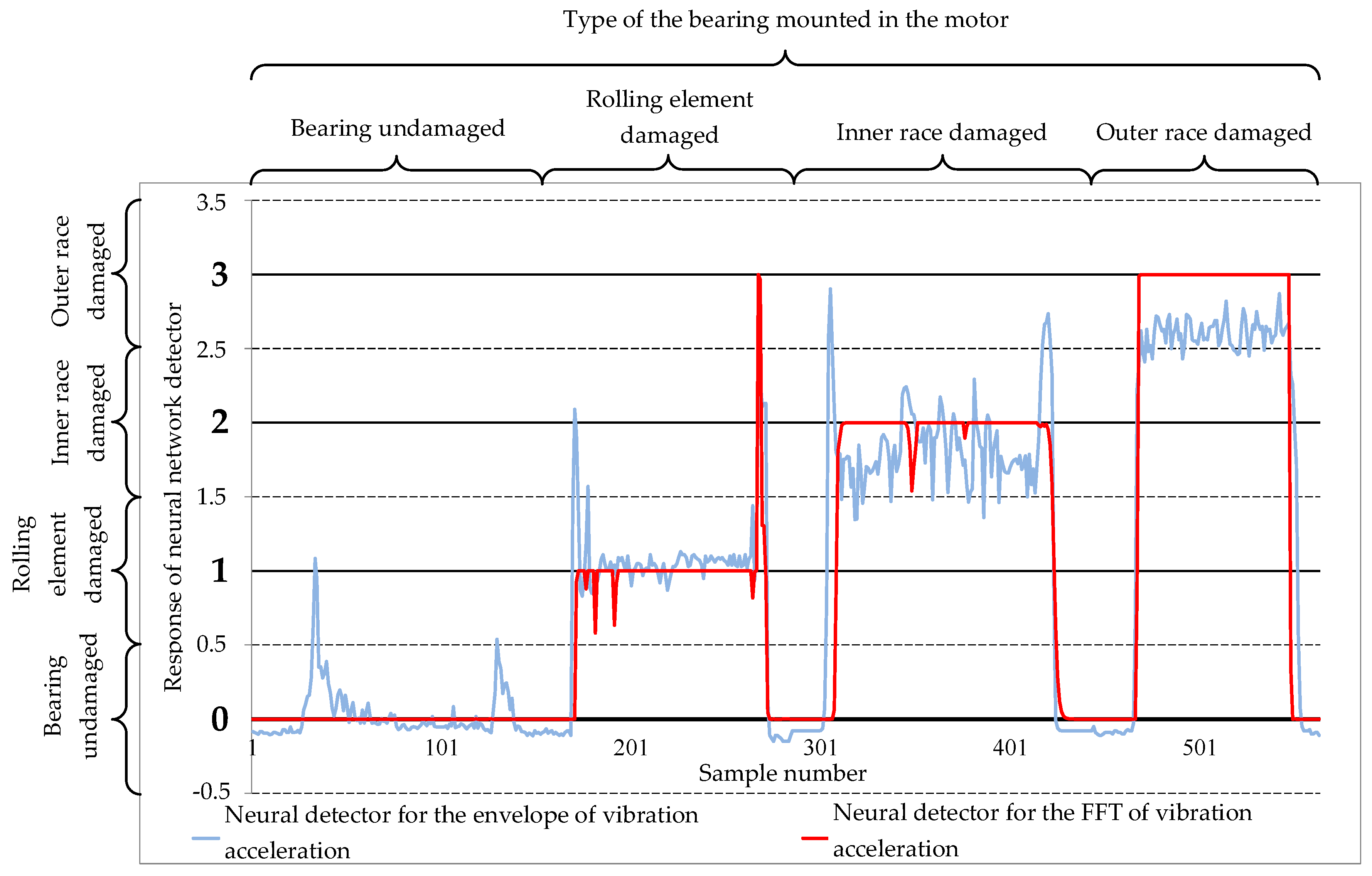
In the two following figures, detailed results of the experimental research are presented. The results were recorded by the developed computer monitoring system. During the research, a measurement buffer was set at 10 s, which allowed us to obtain a spectrum resolution at the level of 0.1 Hz. The moving window technique was applied by refreshing the buffer every second.
The bearings used in the testing of the neural detectors implemented in the developed application were not used in the training process of the NNs. In the figures there is information on the type of tested bearing with a specific fault, mounted in the motor, and the response of suitable NNs (based on the information from the FFT analysis of the vibration acceleration envelope or on the FFT analysis of the vibration acceleration). In each case the motor was started using an autotransformer. Next, the motor was gradually loaded to the rated value. In the last phase the load was switched off and next supply voltage was reduced to zero.
It can be observed in
Figure 11 that both the neural detectors correctly detected the actual condition of the tested bearings. Only at the moment of the load torque change (transient state of the drive) did some errors occur. It can be assumed that the reason for this was the too-slow definition of the actual direction of rotation, which was calculated on the basis of the FFT spectrum for the last 10 s. This problem can be solved by using, e.g., an encoder for speed measurement. The application of FFT spectrum averaging, e.g., for the last 10 samples, results in oscillation reduction of the neural detector output. This approach guarantees higher efficiency at the expense of additional delays in the operation of the real application. In the available literature, NN operating on-line are rarely found. As a rule, the presented results show selected tests for several measurement files. In this paper,
Figure 11 and
Figure 12 present tests of a few minutes long on a real object, which shows the real mode of operation of the neural detectors.
Table 4 shows a summary of the effectiveness of both neural detectors for the presented example. This effectiveness was defined in a manner that included nonstationary state (transients under load torque change), which could have led to the insignificant decrease of the NN’s accuracy. The majority of detector errors based on the information obtained from the FFT analysis of the vibration acceleration envelope occurred in the case of the inner or outer bearing race’s failure. Despite the rather low efficiency for these two cases, the neural detector did not qualify bearings as undamaged.
The operation of neural detectors was also checked in the event of other motor faults. A properly functioning NN-based monitoring and diagnostic system should indicate in such conditions that the motor under test has the bearing undamaged. Detailed results are presented in
Figure 12. In these specific tests, the same type of induction motor was used as in testing the bearings, but its stator winding was specially prepared to enable the physical modeling of inter-turn short-circuit faults (motor on the right-hand-side in
Figure 8). The inter-turn short circuits were modeled by a short-circuit loop connected to selected connectors on the terminal board (
Figure 8). The short-circuit current that flowed in the short-circuit loop was not limited by any resistor. During the tests, the following scenario was realized: motor start-up and speed setting up to 1440 rpm (samples 1–44), 5 inter-turn short circuit faults of the stator winding (samples 45–111), 10 inter-turn short circuit faults (samples 112–163), 4 rotor bar damages (samples 164–210), misalignment (samples 211–261) and motor shutdown (samples 262–288).
Figure 12 also shows the influence of physical disconnection of the short-circuit loop, which required the temporary holding of the terminal board of the tested motor. This action introduced additional interference that was visible in the measurement of vibration. Other interferences were also visible in the response of the envelope-based detector in the ranges of samples 23–33 and 266–276 in
Figure 12. These were caused by the transients of the drive system connected with the motor start-up and shutdown, respectively. It should be mentioned that FFT analysis is only effective for signals that meet stationarity conditions. In the described on-line test of the NN detectors, in both cases the analyzed signals were non-stationary. All measurements concerning the described fault conditions were made at the speed of 1440 rpm. The results obtained show that both detectors correctly classified the different modeled faults as “bearing undamaged”.


