Article

Reconfigurable Hybrid Resonant Topology for Constant Current/Voltage Wireless Power Transfer of Electric Vehicles

1
Department of Electrical and Computer Engineering, Sungkyunkwan University, 2066 Seobu-ro, Jangan-Gu, Suwon 16419, Korea
2
Department of Electrical Engineering, Chonnam National University, 77 Yongbong-ro, Buk-gu, Gwangju 61186, Korea
*
Author to whom correspondence should be addressed.
Electronics 2020, 9(8), 1323; https://doi.org/10.3390/electronics9081323
Submission received: 6 July 2020 / Revised: 12 August 2020 / Accepted: 14 August 2020 / Published: 16 August 2020
(This article belongs to the Special Issue Emerging Technologies for Wireless Power Transfer in Transportation)

Abstract

:
This paper proposes a reconfigurable hybrid topology (RHT) for the constant current (CC)/constant voltage (CV) charging of electric vehicles. The proposed system combines the series–series and the inductor and double capacitors-series topologies. Two AC switches (ACSs) are utilized to change the CC and CV charging modes, without requiring an additional resonant network. A detailed analysis for designing the hybrid topology parameters is also presented; a three-kilowatt prototype was configured based on this analysis in order to validate the proposed system. The constructed prototype confirmed the stable mode changes, load fluctuations, CC/CV output characteristics and efficiency of the proposed system. The maximum efficiency of the proposed RHT was found to be 92.58%.

1. Introduction

Owing to their various advantages, wireless power transfer (WPT) systems have attracted significant attention for their applicability in charging the batteries of electric vehicles (EVs) [1,2,3]. However, compared to conductive charging, WPT is less efficient due to the low coupling coefficient and the various operating conditions. Thus, it is essential to improve the efficiency of this approach.
A constant current/constant voltage (CC/CV) has been widely used to charge EV batteries, because it combines the advantages of both the CC and CV charging methods [4]. Figure 1 presents the CC/CV charging profile. Several conventional schemes can be utilized to achieve CC/CV charging via a WPT system. For instance, additional power converters can be added to the front or post stages of the system for output regulation [5,6,7,8,9]. By adjusting the duty cycle, impedance tracking and CC/CV charging can be realized. However, using such large additional devices lowers the efficiency and increases the volume of the WPT system. Moreover, owing to the limited switching frequency variation (80–90 kHz), as defined by SAE J2954 [10], a few studies [11,12,13,14,15] have combined frequency control and phase-shift (PS) control to realize zero voltage switching and CC/CV charging. However, these methods can increase the reactive current due to the greater current phase angle, which leads to increased conduction losses in several components. Additionally, high-speed communication is required for real-time control, which, in turn, increases the complexity and cost of the system.
Compensation topologies, which consist of passive resonant networks, are used in WPT systems to compensate for the low coupling coefficient. Based on the structure of the resonant network, the compensation circuit features CC or CV characteristics. Thus, by integrating resonant networks and a reconfigurable switching structure, a zero phase angle (ZPA) and CC/CV output can be achieved simultaneously [16,17,18]. This method has garnered considerable research attention because compensation topologies provide easy controllability and are also relatively cheap. In [19], a composite topology, which was a combination of series–series (S–S) and series–parallel (S–P) topologies, is proposed, whereby a CC/CV output could be realized via switching. However, this required three AC switches (ACSs) and a center-tapped transformer, thereby increasing the complexity of the topology. In [20], compensation topologies that enable switching between four resonant networks, i.e., S–S, S–P, parallel–series (P–S) and parallel–parallel (P–P), in order to achieve a CC/CV output are proposed. However, these four compensated networks have limited parameter design freedom and are more sensitive to load variations. Additionally, three ACSs are required to switch between each operating mode. Based on the LCC-S compensation topology for charging EV batteries, a switching hybrid topology is proposed in [21], whereby the CC/CV charging modes can be switched via two ACSs, without changing the structure of the topology. However, because these two ACSs are placed on different sides, high-speed synchronous communication is necessary for accurate mode switching. In [22], for CC and CV outputs, a hybrid and reconfigurable WPT system with a high-misalignment tolerance is proposed. However, the four-coil structure and the large resonant devices utilized increase the cost and volume of the system. Although previous studies have focused on hybrid switching topologies for low-power systems (< one kilowatt), further research on such topologies for high-power systems that are suitable for EVs is essential.
This paper proposes a reconfigurable hybrid topology (RHT) based on the S–S and LCC-S compensation topologies for achieving CC/CV output characteristics. A detailed analysis of each operation mode is presented based on the transformer T model. The compensation circuit parameters are designed to satisfy charging requirements and the ZPA condition. Two ACSs are utilized to switch between the CC and CV charging modes. As these ACSs are both located on the primary side, only a single controller is required to realize load-independent CC/CV charging. The proposed RHT system was verified using a three-kilowatt experimental prototype.

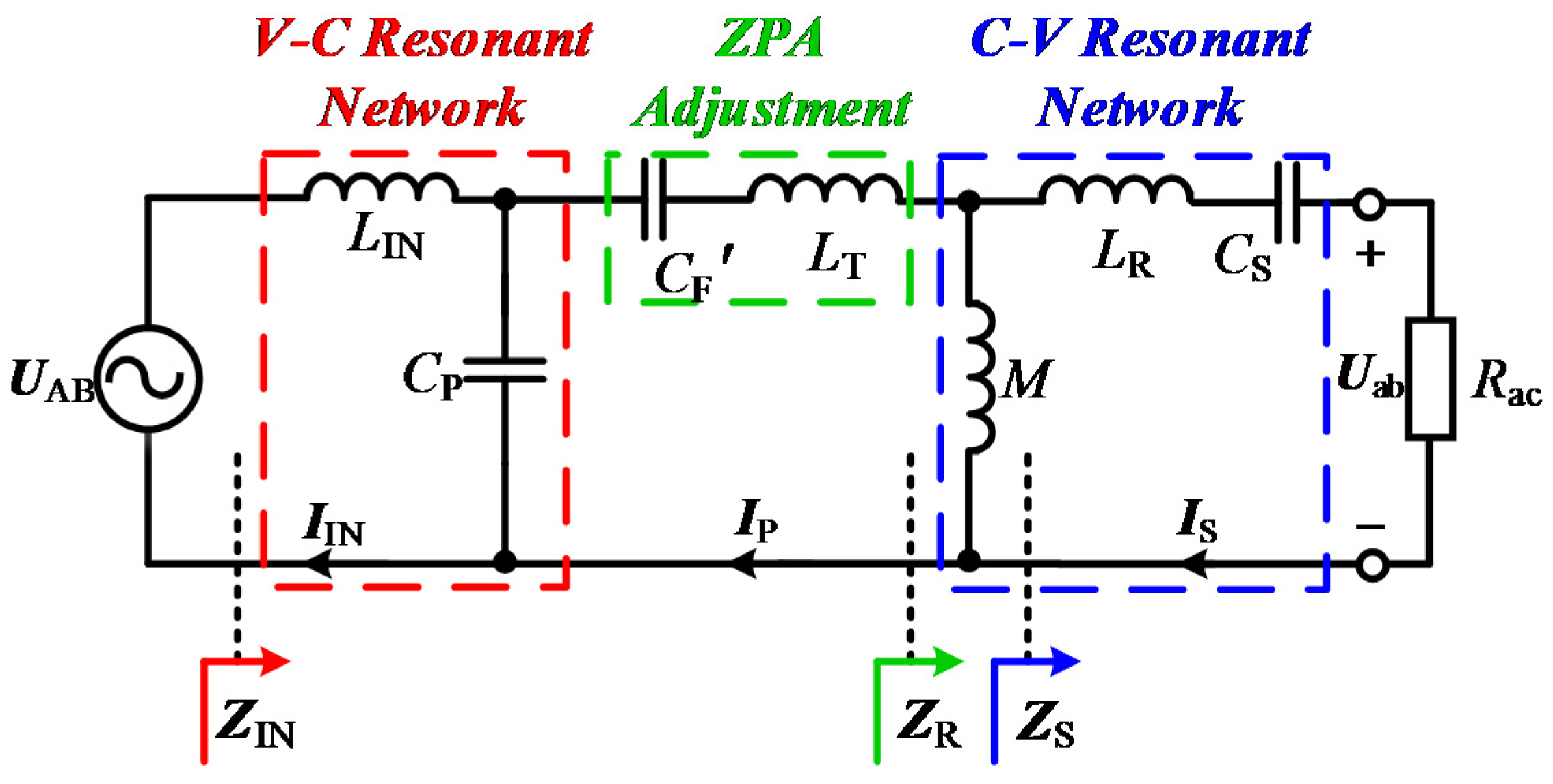
2. Theoretical Analysis of Reconfigurable Topologies

Figure 2 presents the structure of the proposed WPT system based on the RHT. It consists of a full-bridge inverter (FBI), primary-loop compensation inductor LIN, primary-loop series-compensation capacitor Cp, primary-loop shunt-compensation capacitor CF, primary-loop additional-shunt compensation capacitor CAF, secondary-loop series-compensation capacitor CS, rectifier and two additional switches S1 and S2 for the reconfigurable compensation network.
Here, UDC, UAB and IIN are the input DC-link voltage, FBI output voltage and the FBI output current, respectively. UAB can be expanded by using the Fourier series as follows:
U AB = 4 U DC π n = 1 , 3 , 5 sin ( n φ ) n
where φ is the phase difference and n is the harmonics order number. It should be noted that S1 and S2 are the switches to change between the CC and CV modes, respectively. A full bridge rectifier is applied to generate the charging voltage UBat and current IBat, UBat, IBat and RBat can be derived by applying the fundamental harmonic analysis according to [23]:
U Bat = π 2 4 U ab
I Bat = 2 2 π I S
R Bat = π 2 8 R ac
where Uab and IS are the RMS values. The output AC and DC equivalent resistance are defined as Rac = UAB/IS and RBat = UBat/IBat, respectively.
In the WPT system, the primary and secondary coils are considered as a loosely coupled transformer (LCT) because of the small coupling coefficient k. Two LCT circuits models are presented in Figure 3. Here, UP and Ip are the primary coil voltage and current, respectively; US and IS are the secondary coil voltage and current, respectively; and LP and LS are the self-inductances of the primary and secondary coils, respectively. Moreover, M is the LCT mutual inductance. The voltage equations for Figure 3a can be derived by Kirchhoff’s voltage law, as follows:
{ U P = j ω L P I P j ω M I S U S = j ω L S I S + j ω M I P
In addition, the T model parameters can be derived as:
{ L T = L P M L R = L S M
where LT and LR are the primary and secondary leakage inductances of the coils, respectively.

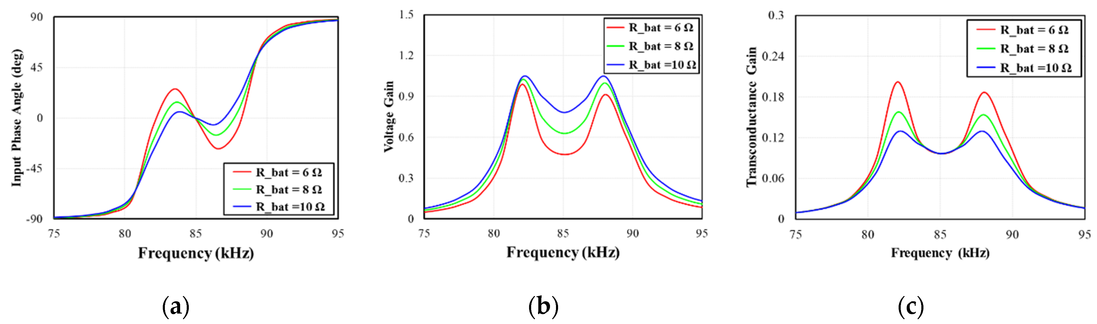
2.1. Constant Current Output Characteristics of Proposed RHT System

As shown in Figure 2, the ACSs S1 and S2 are both turned-off, and the parasitic resistance of each component is neglected. The equivalent T model for the CC mode is shown in Figure 4, where LP and LS are the primary and secondary self-inductances of coils, respectively; M is the mutual inductance; and LT′ is the series equivalent inductance of LT and LIN.
L T = L T + L IN
In order to operate system in ZPA condition, each resonance frequency of the proposed system is defined as one resonance frequency ω0 (hereinafter referred to as the operating angular frequency of the compensation network). If CF is sufficiently high, the series connected LT′ and CF can be considered as an equivalent capacitance C′, that is,
C = C F 1 ω 0 2 L T C F
if C′ is designed to resonate with M, the following equations can be derived:
0 = j ( ω 0 M + 1 ω 0 C )
ω 0 2 = 1 M C = 1 L P C F
I S = j U AB C F M = U AB j ω 0 M
on substituting Equation (11) in Equation (3), under the CC mode, IBat can be derived as:
I Bat = 2 2 π I S = 2 2 U AB ω 0 π M
Provided UAB and mutual inductance M are constant, and the resonant condition in Equation (10) is satisfied, according to Equation (12), IBat is constant and independent of the load, and ZPA can be achieved using a zero reactive power. The total input impedance ZIN can be expressed as:
Z IN = j ( w 0 L T 1 w 0 C F ) + ( j w 0 M Z S )
where the secondary-side equivalent impedance is Z S = j ( ω 0 L R 1 ω 0 C S ) + R ac . Under the condition of ω02 = 1/(LPCF) = 1/(LSCS) and by substituting Equation (2) and Equation (3) into Equation (6), the total input impedance in CV mode ZIN.CV can be simplified as:
Z IN . CV = ( π ω 0 M ) 2 8 R Bat
Based on Equation (7), ZIN.CV presents a resistive characteristic, i.e., ZPA can be achieved. From Equation (4) and Equation (14), the input current in CC mode IIN.CC can be calculated as:
I IN . CC = U AB Z IN . CC = U AB R ac ( ω 0 M ) 2
According to Equation (15), IIN.CC is proportional to Rac. The input phase angle θIN can be calculated using the imaginary (Im) and real (Re) parts of the input impedance as follows:
G V = U ab U AB = U Bat U DC
To calculate the output current and voltage, the voltage gain GV and the transconductance gain GT of the proposed system are defined as follows:
G T = I Bat U AB = I S U DC
Based on the abovementioned equations, the primary curves of the frequency characteristics under the CC mode, based on the parameters listed in Table 1, are presented in Figure 5. ZPA can be achieved at the resonance frequency and the current gain is identical to that at the resonance frequency, as shown in Figure 5c. However, the voltage gain is altered because of the CC characteristic.

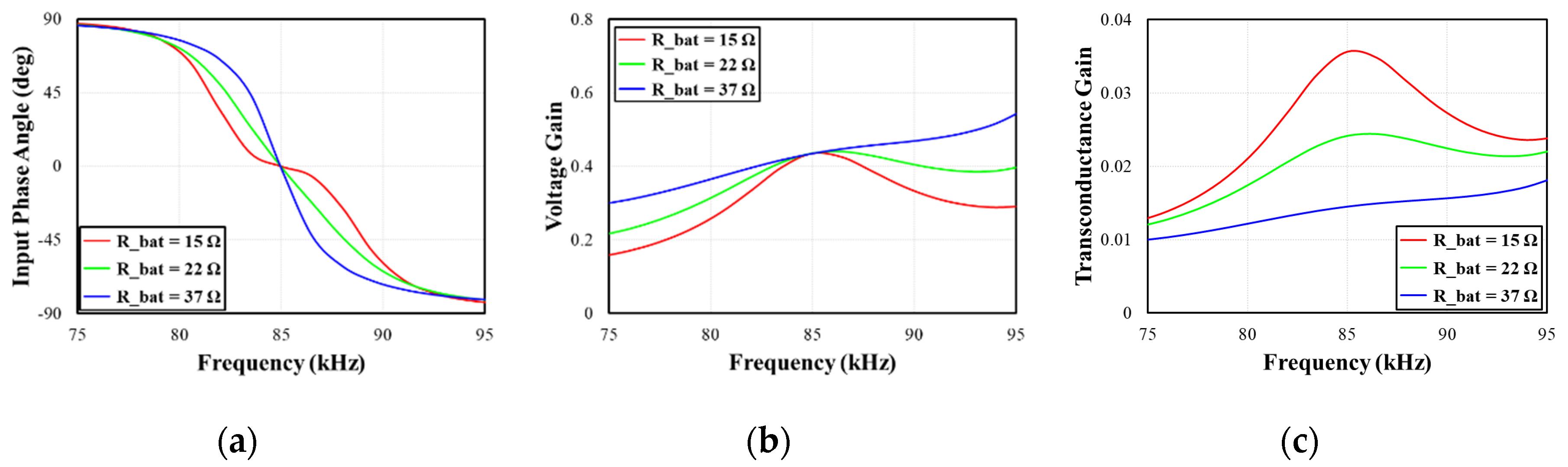
2.2. Constant Voltage Output Characteristics of Proposed RHT System

Figure 6 presents the equivalent circuit for the CV mode when both the ACSs S1 and S2 are ON; this circuit is identical to the LCC-S topology. Here, CF′ is the equivalent parallel capacitance of CF and CAF. To ensure that LIN resonates with CP, that is, ω02 = 1/(LIN CP), the primary coil current IP is determined as follows:
I P = j U AB C P L IN = j U AB ω 0 L IN
The primary current IP has a constant value and is independent of the other parameters under constant UAB and LIN. Provided M resonates with CF and combining with Equation (18), the following equation can be derived:
ω 0 2 = 1 M C F = 1 L S C S
U ab = j ω M I P = M U AB L IN
Substituting Equation (20) into Equation (2), the output battery charging voltage UBat of the CV mode can be expressed as follows:
U Bat = π 2 4 U ab = π 2 4 M U AB L IN
According to Equation (21), the battery-charging voltage UBat is constant and independent of the output load. As shown in Figure 6, the total input impedance ZIN of Figure 6 is calculated as:
Z IN = [ ( j ω 0 L T + 1 j ω 0 C F + ( j ω 0 M Z S ) ) 1 j ω 0 C P ] + j ω 0 L IN
If ω02 = 1/(LINCP) = 1/(LSCS) and by substituting Equation (22) into Equation (4), the condition to achieve ZPA can be derived as:
L IN = ( C F C F + C P ) L P
Under the condition expressed in Equation (13) and by combining it with Equation (2), the input impedance in CV mode ZIN.CV at ZPA the condition can be calculated as:
Z IN . CV = 8 π 2 L IN 2 R Bat M 2
According to Equation (23), it is evident that the ZPA condition can also be achieved in the CV charging mode. From Equation (4) and Equation (24), the input current in CV mode IIN.CV can be calculated as:
I IN . CV = ( M L IN ) 2 U AB R ac
According to Equation (25), IIN.CV is inverse proportional to Rac.
Based on the abovementioned equations, Figure 6 presents the primary curves of the frequency characteristics under the CV mode, considering the parameters listed in Table 1. ZPA can be achieved at the resonance frequency. Compared with Figure 5, the voltage gain remains the same at the resonance frequency, as shown in Figure 7b, whereas the transconductance gain is altered because of the CV characteristic.

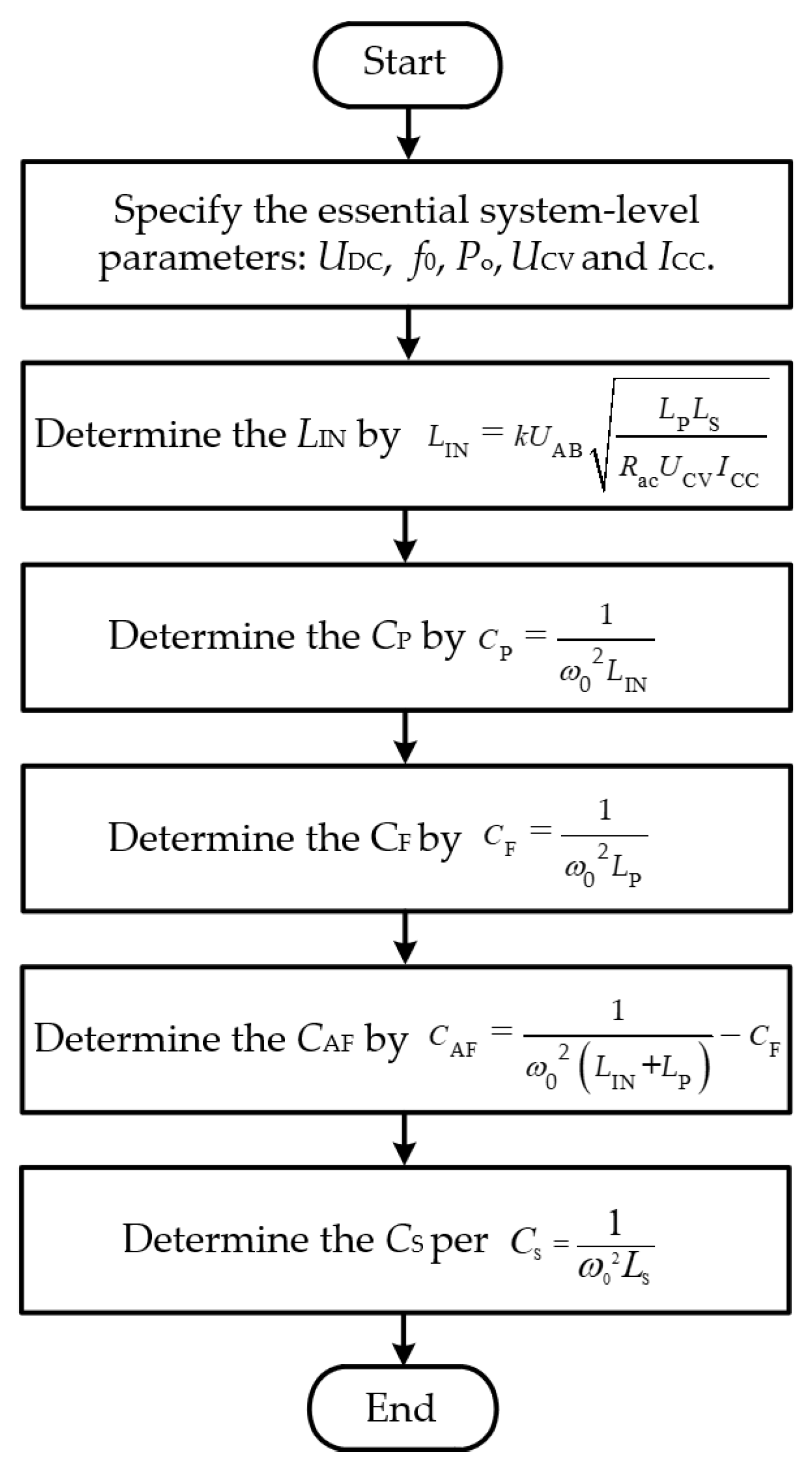
2.3. Design Procedure of Proposed RHT System

The proposed system is based on the S–S and LCC-S compensation networks. Thus, the design procedure is similar with the conventional compensation network design except CAF and CF. In the first, essential system-level parameters for the WPT system should be determined. In this paper, system is designed based on Table 1. UDC, f0, Po, UCV and ICC are 300 V, 85 kHz, 3000 W, 130 V and 23-A, respectively. Where UCV is the constant charging voltage, and ICC is the constant charging current. Moreover, then the primary-loop compensation inductance LIN can be calculated. The primary-loop series compensation capacitance CP is deduced by ω0 and LIN. The primary-loop shunt-compensation capacitance CF is determined by the ω0 and LP, and the equation is deduced by Equation (10). The primary-loop additional-series compensation capacitance CAF can be calculated by using ω0, LIN, LP and CF. Finally, the Secondary-loop series-compensation capacitance is determined by ω0 and LS. In order to operate system under ZPA condition, all parameters should be calculated under same resonance frequency. This design procedure is presented in Figure 8.
The reconfigurable structure of the proposed system with AC switches has a different point compared with conventional system. In the CC mode, two ACSs are turned off, thus, each switch and the additional capacitor current are zero. Voltages of each switch can be calculated by KVL as follows:
V S 2 = | U AB j ω 0 L IN I IN | = U AB 2 + ( L IN U AB R ac ω 0 M 2 ) 2
V S 2 = | I IN j ω 0 C F | = U AB R ac ω 0 3 M 2 C F
In the CV mode, two ACSs are turned on and voltages of ACSs are zero. Currents of ACSs can be deduced by KCL as follows:
I C A F = I S 2 = | C AF C F + C AF I P | = U AB C AF ω 0 L IN ( C F + C AF )
I CP = I S 1 = | I IN I P | = ( M L IN ) 4 ( U AB R ac ) 2 + ( U AB ω 0 L IN ) 2
Voltage stresses of CF and CAF are same because of parallel connection. The voltage stress of the additional capacitor VCAF can be calculated by using ohm’s law as:
V C A F = V C F = | I IN j ω 0 C F | = U AB ω 0 2 L IN C F
Because of high voltage and current stress in IPT system, it is important to analyze maximum voltage and current of each capacitor. From the above equations, Table 2 presents current and voltage stress of capacitors based on Table 1 parameters. Table 2 presents current equations for each capacitor, and the voltage stress can be calculated by using current equations and impedance of each capacitor. In this paper, each capacitor is designed by using multilayer ceramic capacitor (MLCC) with 20% voltage and current margin for safety operation.

3. System Verification and Performance Comparison

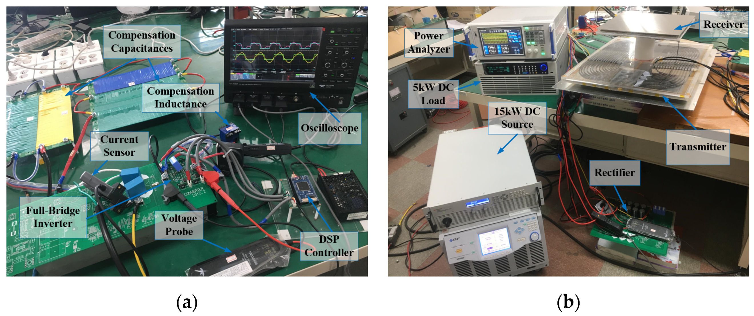
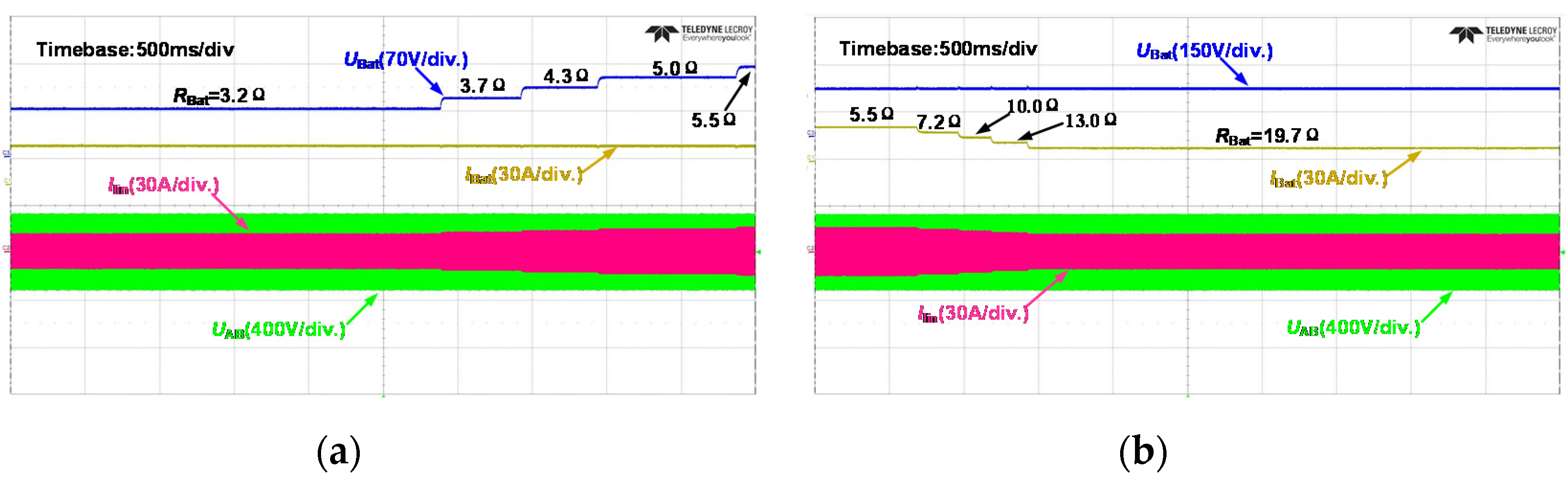
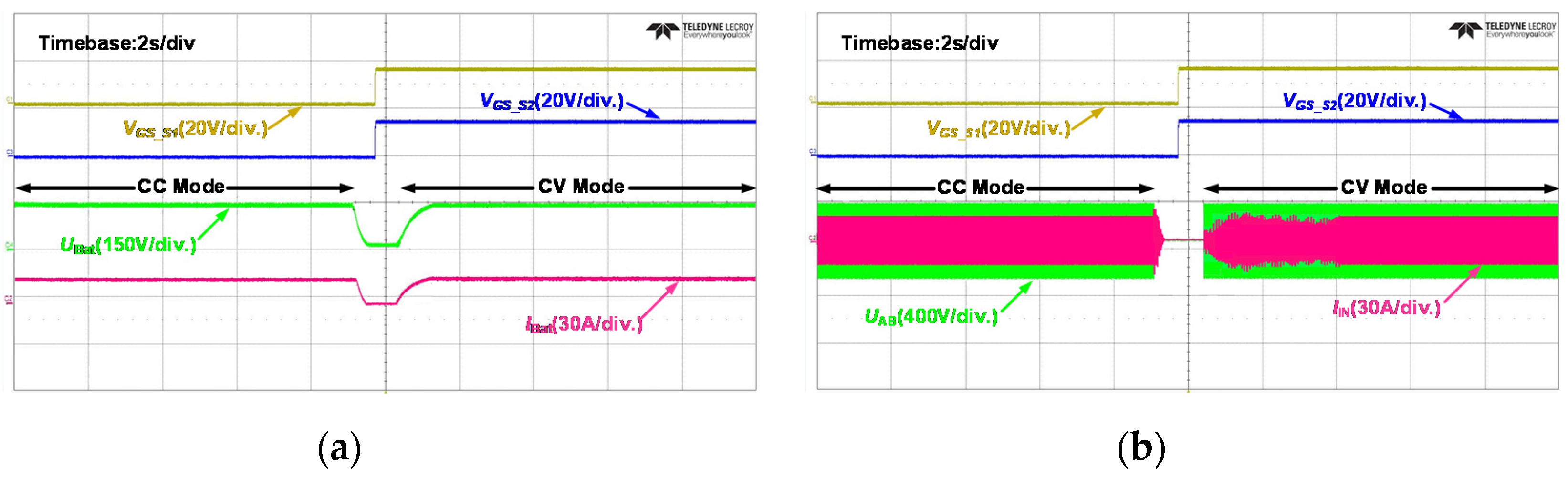
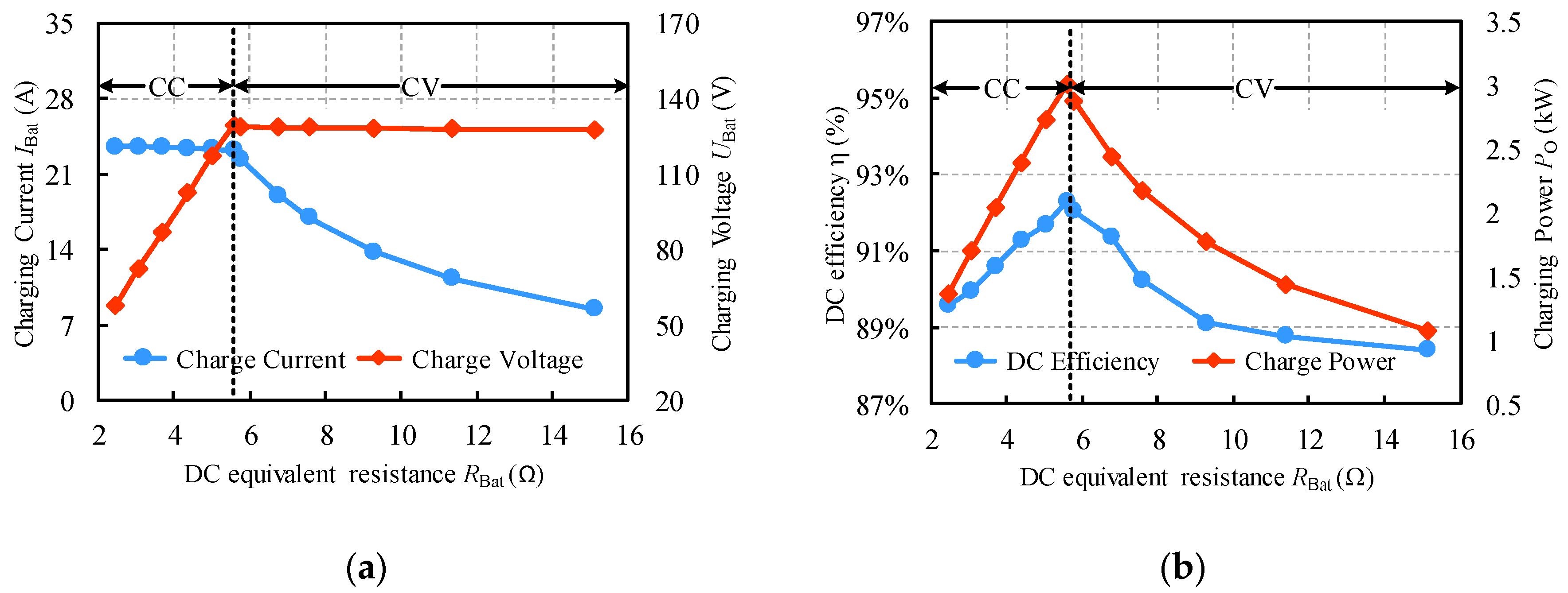
3.1. Experimental Results

To verify the validity and feasibility of the proposed RHT-based WPT system, a 3-kW experimental WPT prototype was fabricated, as shown in Figure 9, according to the parameters listed in Table 1. The practical parameters used are almost identical to the ideal design values.
The experimental waveforms are presented in Figure 10, Figure 11 and Figure 12. Figure 10a,b present the main waveforms of the CC and CV modes. The resonant current Iin and inverter output voltage UAB have almost identical phases because the system is operated near the resonant frequency. Characteristics of the S–S and LCC-S topologies are shown in Figure 10a and Figure 10b, respectively.
The CC and CV mode waveforms under load fluctuations are shown in Figure 11a,b, respectively. When the equivalent DC output resistance changed from 3.2 Ω to 5.0 Ω, the charge current IBat is in the CC mode and the charge voltage UBat in the CV mode remains nearly constant when the load varies from 5.5 Ω to 19.7 Ω. In the CC mode, IIN is varied proportional to RBat. However, in the CV mode, IIN is varied inverse proportional to RBat. These results also can see in Equations (15) and (25). Figure 11 presents the waveforms for the transition from the CC mode to the CV mode. All the results indicate stable operation, which is maintained at nearly CC and CV during the transient state. These experimental results verify the validity of the proposed RHT.
In this study, the values of IBat and UBat are designed to be 23 A and 130 V, respectively. Figure 12 shows the CC/CV charging characteristics of the proposed system. As shown in Figure 13a, as RBat increases, the charge current in the CC mode and the charge voltage in the CV mode are almost constant. Figure 13b depicts the experimental efficiency and charging power. As RBat increases, the charging efficiency and power increase under the CC mode; however, they decrease under the CV mode. The maximum charging efficiency (92.28%) and charge power (3003 W) are observed at the transition point between the two modes (RBat = 5.55 Ω).

3.2. Performance Comparison

In order to evaluate a performance of the proposed RHT system, a comparative analysis is conducted. Table 3 shows detail comparison results of conventional systems and the proposed system. The number of components of [19] and [24] is less than others. However, it cannot apply to the EV application because of low power rate. References [21,22] have over 1000 W power rate and efficiency is relatively high. However, they require many component numbers compared with the proposed system. It can be seen that the proposed system has a small number of components, high power and high efficiency.

4. Conclusions

This study proposes an RHT of a wireless charging system for EVs, whereby CC/CV charging and ZPA can be achieved simply by switching between two ACSs. As these ACSs are both located on the primary side, the proposed system can be easily controlled using a single primary controller, without requiring synchronous wireless communication between the primary and secondary sides. Therefore, the cost and control complexity of the entire WPT system is reduced significantly, than conventional WPT systems. To verify the performance of the proposed system, a three-kilowatt experimental prototype is configured. The experimental results indicate that a maximum charging efficiency of 92.28% and power of 3003 W is achieved. The results also validate the stable operation of the system, even during load fluctuations and mode changes. In conclusion, the proposed system is expected to serve as an effective alternative for various WPT applications.

Author Contributions

Writing-original draft, S.-H.H.; validation, Y.C.; investigation, H.Z.; writing—review & editing, K.-Y.L.; supervision and project administration, D.-H.K. All authors have read and agreed to the published version of the manuscript.

Funding

This research was supported by Korea Electric Power Corporation (Grant number: R18XA04).

Conflicts of Interest

The authors declare no conflict of interest.

References

  1. Kim, C.-G.; Seo, D.-H.; You, J.-S.; Park, J.-H.; Cho, B.-H. Design of a contactless battery charger for cellular phone. IEEE Trans. Ind. Electron. 2002, 48, 1238–1247. [Google Scholar] [CrossRef]
  2. Jang, Y.; Jovanovic, M. A contactless electrical energy transmission system for portable-telephone battery chargers. IEEE Trans. Ind. Electron. 2002, 50, 520–527. [Google Scholar] [CrossRef] [Green Version]
  3. Hui, S.; Ho, W. A new generation of universal contactless battery charging platform for portable consumer electronic equipment. IEEE Trans. Power Electron. 2004, 20, 620–627. [Google Scholar] [CrossRef]
  4. Wang, Z.; Lai, X.; Wu, Q.; Xinquan, L. A PSR CC/CV Flyback Converter with Accurate CC Control and Optimized CV Regulation Strategy. IEEE Trans. Power Electron. 2017, 32, 7045–7055. [Google Scholar] [CrossRef]
  5. Ahn, D.; Kim, S.; Moon, J.; Cho, I.-K. Wireless Power Transfer with Automatic Feedback Control of Load Resistance Transformation. IEEE Trans. Power Electron. 2015, 31, 7876–7886. [Google Scholar] [CrossRef]
  6. Li, H.; Li, J.; Wang, K.; Chen, W.; Yang, X. A Maximum Efficiency Point Tracking Control Scheme for Wireless Power Transfer Systems Using Magnetic Resonant Coupling. IEEE Trans. Power Electron. 2014, 30, 3998–4008. [Google Scholar] [CrossRef]
  7. Ahn, D.; Hong, S. Wireless Power Transfer Resonance Coupling Amplification by Load-Modulation Switching Controller. IEEE Trans. Ind. Electron. 2014, 62, 898–909. [Google Scholar] [CrossRef]
  8. Dai, X.; Li, X.; Li, Y.; Hu, A.P.; Hu, P. Maximum Efficiency Tracking for Wireless Power Transfer Systems With Dynamic Coupling Coefficient Estimation. IEEE Trans. Power Electron. 2017, 33, 5005–5015. [Google Scholar] [CrossRef]
  9. Chen, Y.; Zhang, H.; Park, S.-J.; Kim, D.-H. A Comparative Study of S-S and LCCL-S Compensation Topologies in Inductive Power Transfer Systems for Electric Vehicles. Energies 2019, 12, 1913. [Google Scholar] [CrossRef] [Green Version]
  10. Hybrid—EV Committee Wireless Power Transfer for Light-Duty Plug-in/Electric Vehicles and Alignment Methodology. In SAE Recommended Practice J2954 Apr; SAE International: Warrendale, PA, USA, 2019.
  11. Byeon, J.; Kang, M.; Kim, M.; Joo, D.-M.; Lee, B.K. Hybrid control of inductive power transfer charger for electric vehicles using LCCL-S resonant network in limited operating frequency range. In Proceedings of the 2016 IEEE Energy Conversion Congress and Exposition, Milwaukee, WI, USA, 18–22 September 2016; pp. 978–984. [Google Scholar]
  12. Kim, M.; Joo, D.-M.; Lee, B.K. Design and control of inductive power transfer system for electric vehicles considering wide variation of output voltage and coupling coefficient. IEEE Trans. Power Electron. 2019, 34, 1197–1208. [Google Scholar] [CrossRef]
  13. Patil, D.; Yang, Z.; Fahimi, B. A Wireless Powered EV battery charger for sinusoidal current charging technique with maximum efficiency control. 2017 IEEE Transp. Electrif. Conf. Expo ITEC 2017, 613–620. [Google Scholar] [CrossRef]
  14. Ann, S.; Lee, W.-Y.; Choe, G.-Y.; Lee, B.K. Integrated Control Strategy for Inductive Power Transfer Systems with Primary-Side LCC Network for Load-Average Efficiency Improvement. Energies 2019, 12, 312. [Google Scholar] [CrossRef] [Green Version]
  15. Li, Z.; Huang, X.; Song, K.; Jiang, J.; Zhu, C.; Du, Z. Constant Current Charging and the Maximum System Efficiency Tracking for Wireless Charging Systems Employing Dual-side Control. IEEE Trans. Ind. Appl. 2018, 56, 622–634. [Google Scholar] [CrossRef]
  16. Pantic, Z.; Bai, S.; Lukic, S.M. ZCS LCC-Compensated Resonant Inverter for Inductive-Power-Transfer Application. IEEE Trans. Ind. Electron. 2010, 58, 3500–3510. [Google Scholar] [CrossRef]
  17. Samanta, S.; Rathore, A.K.; Gae, A.K.R. Analysis and Design of Load-Independent ZPA Operation for P/S, PS/S, P/SP, and PS/SP Tank Networks in IPT Applications. IEEE Trans. Power Electron. 2018, 33, 6476–6482. [Google Scholar] [CrossRef]
  18. Hou, J.; Chen, Q.; Wong, S.-C.; Tse, C.K.; Ruan, X. Analysis and Control of Series/Series-Parallel Compensated Resonant Converter for Contactless Power Transfer. IEEE J. Emerg. Sel. Top. Power Electron. 2015, 3, 124–136. [Google Scholar] [CrossRef]
  19. Auvigne, C.; Germano, P.; Ladas, D.; Perriard, Y. A dual-topology ICPT applied to an electric vehicle battery charger. In Proceedings of the 2012 XXth International Conference on Electrical Machines, Marseille, France, 2–5 September 2012; pp. 2287–2292. [Google Scholar]
  20. Qu, X.; Han, H.; Wong, S.-C.; Tse, C.K.; Chen, W. Hybrid IPT Topologies with Constant-Current or Constant-Voltage Output for Battery Charging Applications. IEEE Trans. Power Electron. 2015, 30, 1. [Google Scholar] [CrossRef]
  21. Chen, Y.; Zhang, H.; Park, S.-J.; Kim, D.-H. A Switching Hybrid LCC-S Compensation Topology for Constant Current/Voltage EV Wireless Charging. IEEE Access 2019, 7, 133924–133935. [Google Scholar] [CrossRef]
  22. Chen, Y.; Yang, B.; Kou, Z.-H.; He, Z.; Cao, G.-Z.; Mai, R. Hybrid and Reconfigurable IPT Systems With High-Misalignment Tolerance for Constant-Current and Constant-Voltage Battery Charging. IEEE Trans. Power Electron. 2018, 33, 8259–8269. [Google Scholar] [CrossRef]
  23. Steigerwald, R.L. A comparison of half-bridge resonant converter topologies. IEEE Trans. Power Electron. 1987, 3, 174–182. [Google Scholar] [CrossRef]
  24. Zhang, H.; Chen, Y.; Park, S.-J.; Kim, D.-H. A Hybrid Compensation Topology with Single Switch for Battery Charging of Inductive Power Transfer Systems. IEEE Access 2019, 7, 171095–171104. [Google Scholar] [CrossRef]
Figure 1. Constant current/constant voltage (CC/CV) charging profile.
Electronics 09 01323 g001
Figure 2. Circuit diagram of the proposed wireless power transfer (WPT) system based on reconfigurable hybrid topology (RHT).
Electronics 09 01323 g002
Figure 3. LCT equivalent circuits. (a) M model; (b) T model.
Electronics 09 01323 g003
Figure 4. Equivalent T models of the proposed RHT for the CC mode.
Electronics 09 01323 g004
Figure 5. Frequency characteristics of the proposed RHT for the CC mode. (a) Input phase angle; (b) voltage gain; (c) transconductance gain.
Electronics 09 01323 g005
Figure 6. Equivalent T models of the proposed RHT for CV mode.
Electronics 09 01323 g006
Figure 7. Frequency characteristics of the proposed RHT for the CV mode. (a) Input phase angle, (b) voltage gain and (c) transconductance gain.
Electronics 09 01323 g007
Figure 8. Flowchart for key parameters design of the proposed system.
Electronics 09 01323 g008
Figure 9. Three-kW experimental prototype. (a) Compensation devices; (b) main instruments.
Electronics 09 01323 g009
Figure 10. Key waveforms at maximum power. (a) CC mode; (b) CV mode.
Electronics 09 01323 g010
Figure 11. Experimental waveforms under load fluctuation: (a) CC mode and (b) CV mode.
Electronics 09 01323 g011
Figure 12. Experimental waveforms for the transition from CC to CV modes. (a) Ubat and Ibat; (b) UAB and IIN.
Electronics 09 01323 g012
Figure 13. Charging characteristics of the proposed system. (a) Experimental charging profile; (b) charging efficiency and power.
Electronics 09 01323 g013
Table 1. Key parameters of the proposed system.
NoteSymbolValue
DC-link voltageUDC300 V
Resonance frequencyf085 kHz
Maximum charging powerPo3000 W
Constant charging voltageVCV130 V
Constant charging currentICC23 A
Coupling coefficientk0.09
Primary coil self-inductanceLP203.37 µH
Secondary coil self-inductanceLS226.22 µH
Primary-loop compensation inductanceLIN44.68 µH
Primary-loop series compensation capacitanceCP78.54 nF
Primary-loop additional-series compensation capacitanceCAF8.03 nF
Primary-loop shunt-compensation capacitanceCF22.22 nF
Secondary-loop series-compensation capacitanceCs15.33 nF
Table 2. Current and voltage stress of capacitors.
CPCFCAFCS
Capacitance (nF)78.5422.228.0315.33
Current (A)16.8511.283.0025.76
Current Equation(29)(17)(28)(11)
Voltage (V)631.26953.71953.713158.68
Table 3. Comparison between the proposed RHT and conventional works.
Proposed[19][20][21][22][24]
Inductors101141
Capacitors432583
ACSs233221
Location of ACSsTransmitterReceiverTransmitterBoth sidesReceiverTransmitter
Coils232242
Control FrequencyFixedFixedFixedFixedFixedChanged
Power3000 W151 W15 W2500 W1000 W200 W
Efficiency92.58%88%92.8%89.28%93.9%87%

