Article

Two-Step Multiuser Equalization for Hybrid mmWave Massive MIMO GFDM Systems

1
Instituto de Telecomunicações (IT) and Departamento de Eletrónica, Telecomunicações e Informática (DETI), University of Aveiro, 3810-193 Aveiro, Portugal
2
Instituto de Telecomunicações (IT) and Faculdade de Ciências e Tecnologia, University Nova de Lisboa, 1099-085 Lisboa, Portugal
*
Author to whom correspondence should be addressed.
Electronics 2020, 9(8), 1220; https://doi.org/10.3390/electronics9081220
Submission received: 30 June 2020 / Revised: 23 July 2020 / Accepted: 24 July 2020 / Published: 29 July 2020

Abstract

:
Although millimeter-wave (mmWave) and massive multiple input multiple output (mMIMO) can be considered as promising technologies for future mobile communications (beyond 5G or 6G), some hardware limitations limit their applicability. The hybrid analog-digital architecture has been introduced as a possible solution to avoid such issues. In this paper, we propose a two-step hybrid multi-user (MU) equalizer combined with low complexity hybrid precoder for wideband mmWave mMIMO systems, as well as a semi-analytical approach to evaluate its performance. The new digital non-orthogonal multi carrier modulation scheme generalized frequency division multiplexing (GFDM) is considered owing to its efficient performance in terms of achieving higher spectral efficiency, better control of out-of-band (OOB) emissions, and lower peak to average power ratio (PAPR) when compared with the orthogonal frequency division multiplexing (OFDM) access technique. First, a low complexity analog precoder is applied on the transmitter side. Then, at the base station (BS), the analog coefficients of the hybrid equalizer are obtained by minimizing the mean square error (MSE) between the hybrid approach and the full digital counterpart. For the digital part, zero-forcing (ZF) is used to cancel the MU interference not mitigated by the analog part. The performance results show that the performance gap of the proposed hybrid scheme to the full digital counterpart reduces as the number of radio frequency (RF) chains increases. Moreover, the theoretical curves almost overlap with the simulated ones, which show that the semi-analytical approach is quite accurate.

1. Introduction

The number of users in telecommunication systems has grown rapidly in recent years, which led to work for the next generations of wireless networks in order to achieve the desired requirements in terms of reaching to higher data rates, reliable services, robustness, and spectral efficiency. For that reason, the predict key enabling technologies for the evolution of mobile technologies towards beyond 5G and 6G include the following: (1) the use of millimeter-wave (mmWave) frequency bands, as the conventional sub-6 GHz frequency spectrum, used by cellular communications networks, is currently saturated; and (2) the use of a massive number of antennas, called massive multiple input multiple output (MIMO) (mMIMO) or large-scale MIMO [1]. The implementation of mMIMO is very desirable for the smaller wavelength of the mmWave frequencies as it can improve the link reliability [2] and mitigate the antenna array size restrictions to deal with the possibility of arranging more antennas into the confined space [3,4].
It is of paramount importance to look forward to the features of the beamforming techniques introduced by mmWave mMIMO, which has an important and attractive role in combating the limitation of high path loss (PL) [5,6]. Although the use of mmWave mMIMO is very attractive, the high cost and power consumption of mixed-signal components can be considered the main drawbacks to achieve full digital systems, that is, systems where each antenna is connected with a fully dedicated radio frequency (RF) chain [7,8]. A simple approach, so-called full analog beamforming with only phase shifters, has been proposed to overcome the large number of RF chains issue [9]. However, the full analog signal processing is just used for single-stream transmission, and its performance is limited by constraints on the amplitude and quantized phase shifters [10]. Then, a new architecture was addressed in [11], so-called hybrid analog-digital architecture, where the number of RF chains is much lower than the number of antennas in order to cope with the hardware constraints. In this approach, part of the signal processing is implemented in the analog domain, while a lower complexity processing is left to the digital domain.
Concerning wireless channel access and sharing, digital communication technologies have become more sophisticated and reliable, as they can operate with higher spectral efficiency. One of the most relevant specifications in the physical layer of the wireless system is the technology used to access and share the wireless channel. For this reason, the communications systems integrate multi carrier transmission technologies in order to accomplish their target, and thus orthogonal frequency division multiplexing (OFDM) is implemented in 4G (LTE downlink) systems owing to its ability to achieve high data rates transmission [12]. Although the use of OFDM is suitable for transmitting signals via a multipath propagation scenario, where frequency selective fading is verified at the channel response, the large peak signal that formed by the random sum of the phase subcarriers results in a high peak to average power ratio (PAPR). Therefore, a large power back-off is required for the power amplifiers, or then non-linear distortions will degrade the system performance [12]. Moreover, OFDM presents relatively high levels of out-of-band (OOB) emissions induced because of using rectangular pulse shaping filter in the transmitter, which results in strong interference into neighboring frequency bands [13]. That is why other waveform candidates were evaluated and proposed as an alternative of OFDM to overcome such problems, such as constant envelope OFDM (CE-OFDM), filter bank multi carrier (FBMC), universal filtered multi carrier (UFMC), and generalized frequency division multiplexing (GFDM). These modulation schemes are suitable for future systems (beyond 5G/6G), and GFDM can be considered the most flexible non-orthogonal multi carrier transmission scheme, among others [14].

1.1. Previous Works on Hybrid Architectures

In recent years, some works have been proposed for narrowband hybrid analog-digital systems [15,16,17,18,19,20,21,22]. In [15], the spatially scattering structure of mmWave channels was explored to formulate the hybrid RF/baseband beamforming scheme as a sparse reconstruction signal recovery problem. Then, the principle of orthogonal matching pursuit (OMP) algorithm is applied to develop the algorithms that accurately approximate optimal unconstrained precoders and combiners as a linear combination of beam steering vectors. To handle the inter-user interference, a hybrid MU algorithm was proposed for the uplink in [16]. This algorithm is based on the Gram–Schmidt method to compute the analog vectors, and then the minimum mean square error (MMSE) beamforming is performed over the effective channel. The authors in [17] proposed an efficient iterative algorithm for a single antenna user terminals (UTs) system to overcome the multiple access interference obtained in the scatterer-share circumstance, based on the joint hybrid analog-digital precoder and combiner design for mmWave by exploiting the duality of the uplink and downlink MU-MIMO channels. The OMP algorithm was employed for selecting the analog precoder-combiner pair to increase the channel gain, while the MMSE approach was used to get the digital combiner. A hybrid precoder for the downlink MU-MIMO system based on angles of departure (AoDs) in frequency division duplex (FDD) systems was proposed in [18]. First, the beam steering and zero-interference conditions are assumed, and then a decomposition is performed in the analog and digital parts without losses, as these parts are jointly designed. The authors of [19] proposed beamforming methods, where the phase shifters are replaced by switches. In the first method a sub-connected phase shifter network is combined with a full connected switch architecture to reduce the number of the phase shifters. Then, the full connected switches are replaced by a sub-connected switch network with the aim of simplifying the switch network. A hybrid beamforming for optimizing beam control vectors based on a low complexity codebook and signal to interference and noise ratio (SINR) maximization was proposed in [20]. In the analog part, an optimization algorithm is used to alternately optimize the vectors of the receiver and transmitter. Then, the digital part is computed using the equivalent channel and singular value decomposition (SVD). The authors of [21] proposed a low-complexity hybrid beamforming scheme, considering an alternating MMSE algorithm on the basis of the traditional MMSE algorithm to minimize the MSE of the transmitted and received signals, using the orthogonality of the digital matrix and the idea of an iterative update. In order to maximize the energy efficiency of narrowband mmWave MIMO interference channels involving internet of things (IoT) devices, the authors in [22] designed a low-complexity two-stage hybrid transceiver, considering both perfect and imperfect channel state information (CSI).
Although the previous solutions focused on hybrid beamforming approaches for narrowband systems, wideband communications systems are expected for future systems (beyond 5G or 6G). Therefore, the solutions for hybrid mmWave mMIMO wideband systems are of paramount importance. Some works were addressed for hybrid full connected architectures in [23,24,25]. In [23], a precoding algorithm is proposed and efficient hybrid codebooks are developed in order to maximize the mutual information that can be obtained for any particular RF codebook. For each subcarrier, different digital precoding is performed in the frequency domain, while the analog precoder remains constant over the subcarriers. In [24], hybrid precoders for downlink space division multi access (SDMA) and orthogonal frequency division multi access (OFDMA) systems were addressed. The main purpose of the proposed low complexity hybrid precoder is to minimize the total transmit power of the BS, under data rate requirements of users and coverage constraint of signaling broadcasting. For this solution, iterative optimizations between analog and digital precoders are not required. In [25], a full iterative solution was proposed, where the analog and digital parts are iteratives. This approach introduced optimal performance in terms of removing the residual MU and inter-symbol interferences (ISIs). The previous schemes require a high number of phase shifter and connections.
To solve the issues of complexity and power consumption of hybrid full connected architectures, some approaches were addressed for hybrid sub-connected architectures in [26,27], but with losses in terms of performance. In the sub-connected architectures, each RF chain is only connected to a sub-set of antennas. The authors of [26] designed an efficient MU linear equalizer combined with full analog precoder for uplink single carrier-frequency division multiple access (SC-FDMA) systems. They considered single RF low complexity UTs using an efficient full analog precoder based on the knowledge of partial CSI. Then, at BS, the hybrid equalizer is optimized by minimizing the average BER. Finally, a hybrid MU equalizer based on a dynamic subarray antennas structure was proposed in [27]. In the first step, the analog part of equalizer is designed, where a dynamic antenna mapping algorithm is applied to connect each RF chain to antennas, and the phase of each phase shifter is computed. The analog equalizer is constant over the iterations and subcarriers owing to the hardware constraints. Then, the digital equalizer is computed iteratively over the subcarriers based on the iterative block decision feedback equalization (IB-DFE) principle.

1.2. Previous Works on GFDM

The principle of GFDM in dividing the input bits stream into several subcarriers and several subsymbols, and applying the impulse response of an appropriate pulse shaping filter circularly to each subcarrier, are the main factors in reducing the OOB emissions and PAPR experienced by OFDM [28]. On the other side, the cyclic pulse shaping filters lead to losing the orthogonality between the subcarriers, and thus the adjacent subcarriers may interfere causing inter-carrier interference (ICI). This leads to a degradation in the performance of the GFDM system [14]. As the pulse shaping filter has a clear impact on the performance of GFDM, there are many studies in the literature about this topic [28,29,30,31,32,33]. In [28], the widely used filter in GFDM systems is the raised cosine (RC) filter, which is considered a non-casual ideal filter. In practice, this type of filter increases the OOB signal radiations, and thus system delay. For that reason, in [29], different types of improved Nyquist pulse shaping filters are used in combination with the GFDM ZF receiver. The study showed that the proposed filter has lower OOB emissions and a better symbol error rate (SEP) performance compared with root-raised cosine (RRC) in the case of using 16-quadrature amplitude modulation (16-QAM) transmission over an additive white Gaussian noise (AWGN) channel. The OOB emissions and SER of ramp-based pulse shaping filter of GFDM system with RRC and Xia filters for AWGN channel are compared in [30]. This type of filter has better SEP performance and lower OOB emission compared with RRC and Xia pulses, while Xia filter outperforms RRC in terms of OOB radiation. In [31], the authors introduced the results of the proposed new pulse shaping filter from the linear combination of the two pulse shapes. The proposed pulse resulted in better OOB emissions and better resistance to ISI owing to the vertical and horizontal pulse sharpness compared with RRC filter. Another solution was presented in [32], where the quadratic programming (QP) approach is applied as a newly designed pulse shaping filter to reduce the OOB emissions. Moreover, the authors in [33] presented how to modify the GFDM modulation technique to give the same FBMC performance. Therefore, the study introduced the BER performance of GFDM and FBMC schemes under three different channel models: AWGN, time-invariant frequency-selective, and time-variant frequency-selective. This modification led to achieving a linear filtering behavior that can provide an improvement in the OOB emissions.

1.3. Contributions

In this paper, we propose for the uplink a hybrid analog-digital MU equalizer for wideband mmWave mMIMO systems using GFDM as an access technique. To the best of our knowledge, hybrid MU equalizer schemes specifically designed for mmWave mMIMO GFDM systems have not been addressed in the literature yet. Given the hardware limitations of these systems, our design options are as follows:
  • The use of GFDM, which deals with multi-path effects as the OFDM scheme, but the OOB emissions and PAPR issues are decreased.
  • The use of low-complexity UTs, employing a phase shifter network to perform the analog precoding. Two types of analog precoders are used based on the levels of CSI knowledge at the UTs: random and AoD-based precoders.
  • The use of hybrid analog-digital receiver structure, because to have one dedicated RF chain per antenna would be impractical owing to hardware costs and power consumption.
  • It is assumed that the analog coefficients are constant over the subcarriers owing to hardware constraints, because, if the analog equalizer is designed as a frequency selective filter, additional hardware would be needed. This assumption is followed by most of the previous works on hybrid beamforming [23,24,25].
The main contributions of this paper are as follows:
  • The analog coefficients are derived by minimizing the MSE between the hybrid approach and the full digital counterpart. They are computed by selecting a set of vectors from a dictionary based on array response vectors of channel.
  • The ZF criterion is considered at the digital part on a per subcarrier basis to remove the interference not mitigated on the analog part.
  • A semi-analytical, yet accurate approach for obtaining the performance of the proposed hybrid GFDM system is also proposed.
The remainder of this paper is organized as follows. Section 2 describes the system model considered in this work. Section 3 and Section 4 present the design of the transmitter and receiver, respectively. Finally, the main performance results are shown in Section 5 and the conclusions are drawn in Section 6.

1.4. Notations

Boldface capital letters denote matrices and the boldface lowercase letters denote column vectors. The function d i a g ( a ) correspond to a diagonal matrix A with diagonal entries equal to vector a , and d i a g ( A ) gives a diagonal matrix with entries equal to the diagonal entries of the matrix A. The operations ( . ) * , ( . ) T , and ( . ) H represent the conjugate, transpose, and Hermitian transpose of a matrix, respectively. { α l } l = 1 L denotes an L length sequence. The vector a = [ a q ] 1 q Q 1 Q 1 Q 2 and the matrix A = [ A q ] 1 q Q 1 Q 1 Q 2 × L are the concatenation of vector a q Q 2 and matrix A q Q 2 × L , respectively. A ( i , j ) denotes the element at row i and column j of the matrix A . The matrix I M and Z M = M 1 / 2 exp ( j 2 π i j / M ) , i , j = 0 , , M 1 , are the identity matrix and the discrete Fourier transform (DFT) matrix, with size M × M . Finally, the indices k , m , and u refer to the subcarrier, time slot, and UTs, respectively.

2. System Model

In this manuscript, we consider an uplink mmWave mMIMO hybrid analog-digital system that uses GFDM as the access technique. The GFDM block has K subcarriers, M timeslots, and N samples per symbol ( N = K L ), where L is the oversampling factor. This system is designed for U UTs sharing the same radio resources. Each user transmits one data stream per subcarrier, and has N t x transmitting antennas and a single RF chain. The base station is equipped with a number of RF chains ( N r x R F ) lower or equal than the number of receiving antennas ( N r x ), that is, U N r x R F N r x .
The frequency domain clustered channel matrix of the u th user is H u , l N r x × N t x , l = 0 , , N M 1 , where N c l denotes the number of clusters and N r a y denotes the number of paths per cluster, as discussed in [25] and given by
H u , l = d = 0 D 1 H u , d e j 2 π l N M d ,
where H u , d is the channel in time domain and can be expressed as
H u , d = N r x N t x ρ P L q N c l r N r a y ( α q , r u p r c ( d T s τ q u τ q , r u ) a t x , u ( θ q u ϑ q , r u ) a r x , u H ( ϕ q u φ q , r u ) ) ,
noting that E [ H u , d F 2 ] = N r x N t x and the remaining variables are as follows:
  • ρ P L is the path loss (PL) between the UTs and the BSs;
  • α q , r u is the complex path gain at the r th ray of the q th scattering cluster;
  • p r c ( . ) is the pulse shaping filter function, where T S , τ q u , and τ q , r u are the sampling interval, the time delay of q th scattering cluster, and the relative time delay, respectively;
  • a t x , u ( θ q u ϑ q , r u ) denotes the normalized transmitting array response vector with the AoD θ q u and the relative angle of departure ϑ q , r u at the r th ray of the q th scattering cluster;
  • a r x , u ( ϕ q u φ q , r u ) denotes the normalized receiving array response vector with the angle of arrival (AoA) ϕ q u and the relative angle of arrival φ q , r u at the r th ray of the q th scattering cluster.
For a uniform linear array (ULA), the normalized array response vector is [15]
a U L A ( ϕ ) = 1 N a n t [ 1 , e j 1 2 π λ d sin ( ϕ ) , e j 2 2 π λ d sin ( ϕ ) , , e j ( N a n t 1 ) 2 π λ d sin ( ϕ ) ] T ,
where λ is the wavelength, d is the inter element spacing, and N a n t is the number of array antennas elements. The path delays have a uniform distribution in [ 0 , D T s ] , where D T s denotes the maximum channel ray delay with significant power and, for the angles, the random distribution presented in [23] is assumed. The power α q , r u has a decay equal to β q 1 , q 2 from the q 1 th cluster to the q 2 th cluster, and a decay equal to β q , r 1 , r 2 from the r 1 th ray to r 2 th ray of the q th cluster.

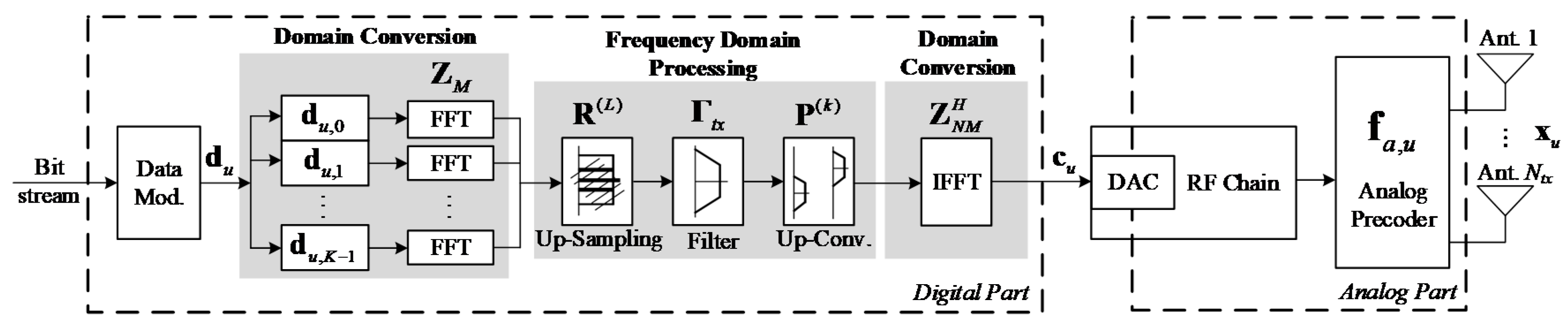
3. Transmitter Design

This section introduces the proposed GFDM transmitter. First, the transmitter model is presented, followed by two analog precoders based on different levels of CSI knowledge. In the first one, we assume that the UT has no CSI knowledge, while in the second one, partial CSI knowledge (the average AoD of each cluster) is assumed.

3.1. Transmitter Model

The block diagram of the transmitter side is based on the low complexity modulation scheme GFDM and has two main parts, digital and analog, as depicted in Figure 1. In the digital part, first the input bit stream d u = [ d u , 0 , d u , 1 , , d u , K M 1 ] T K M is modulated by a M-ary QAM (M-QAM) constellation and then divided into K vectors of complex valued data symbols d u , k = [ d u , l ] l = k M ( k + 1 ) M M . Each vector is spread on the K subcarriers and M time slots. The converting process from time to frequency domain can be applied by Z M M × M to each d u , k , where the result Z M d u , k represents the data at subcarrier k in the frequency domain [34]. The transformed vector Z M d u , k is passed through the second frequency domain processing block that contains three stages. These stages in Figure 1 correspond to the three blocks (up-sampling, filtering, and up-conversion operations). Each operation may be represented by a matrix, thus the signal at the output of each block is equal to the signal at the input multiplied by the corresponding matrix. Therefore, the repetition matrix R ( L ) that has the identity matrices I M is applied to the obtained frequency samples,
R ( L ) = [ I M , , I M ] L T L M × M ,
in order to duplicate the samples L times. Then, to each subcarrier, the diagonal of the pulse shaping filter matrix Γ t x = diag ( Z L M g ) L M × L M that contains the frequency samples of the filter g will be applied. Herein, the functionality of the permutation matrix P ( k ) N M × L M on the k th subcarrier signal is used to circular up-convert the signal from base-band to band-pass, where P ( 1 ) = [ I L M , 0 L M , 0 L M , ] T , P ( 2 ) = [ 0 L M , I L M , 0 L M , ] T , … with 0 L M , a square matrix that contains zero elements [34]. At last, in the second domain conversion block, all subcarriers signal are superimposed and transformed to the time domain c u = [ c u , 0 , , c u , N M 1 ] T N M by applying inverse discrete Fourier transform (IDFT) matrix Z N M H , where
c u = Z N M H k = 0 K 1 ( P ( k ) Γ t x R ( L ) Z M d u , k )
It is of paramount importance to mention that the transmitter model of GFDM can be represented by a single matrix in order to facilitate the application of standard receiver methods such as matched filter (MF), ZF, and minimum mean square error (MMSE). In this case, the matrix representation Equation (5) can be rewritten as
c u = Z N M H A d u ,
where A = [ A 0 , A 1 , , A K 1 ] N M × K M is the complex-valued modulation matrix that contains all transmitted signals as A k = P ( k ) Γ R ( L ) Z M N M × M . Finally, transmitted signal x u , l N t x is obtained after applying the analog precoder f a , u N t x , as
x u , l = f a , u c u , l , l = 0 , N M 1
The analog precoder elements are phase shifters, that is, | f a , u ( i ) | 2 = N t x 1 , and because of the hardware constraints, its entries have the same amplitude. For the analog precoder, we address two cases of the availability of the CSI knowledge at the transmitter side. First, we proposed a random precoder where each UT has no access to CSI. Then, on the basis of [23], we suppose that the UT has access to a partial CSI, that os, only the average AoD of each channel cluster.

3.2. No CSI-Based Precoder

The transmitter here has no access to the CSI, which means that the analog precoder vector of the u th UT is generated randomly accordingly to
f a , u = [ e j 2 π ϕ n u ] 1 n N t x
noting that ϕ n u [ 0 , 1 ] , where n { 1 , , N t x } and u { 1 , , U } , are i.i.d. uniform random variables.

3.3. Partial CSI-Based Precoder
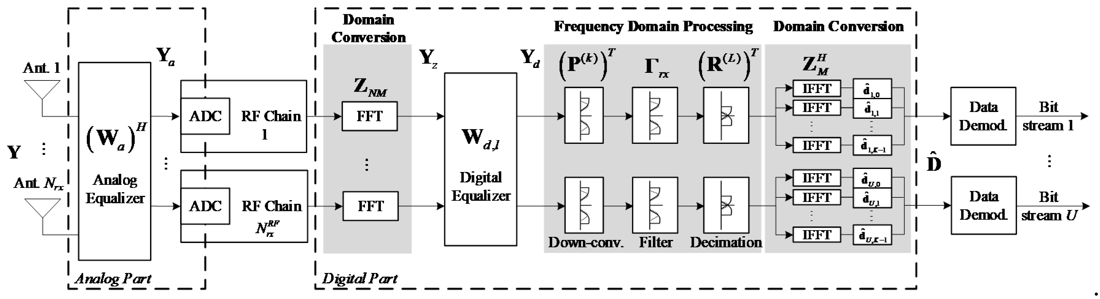
The main purpose of this approach is to maximize the required user’s power and conduct the beam to the dominant direction of the channel. Therefore, based on the channel model described in Section 2, first we must build the following matrix:
A t x , u = [ a t x , u ( ϕ 1 t x , u ) , , a t x , u ( ϕ N c l t x , u ) ] N t x × N c l ,
where a t x , u ( ϕ q t x , u ) , q = 0 , , N c l 1 is given by (3) and ϕ q t x , u is the average AoD of the qth cluster. Then, the eigenvalue decomposition of A t x , u A t x , u H = Λ t x , u Σ t x , u Λ t x , u H is computed. Finally, the dominant channel direction is selected to use in the analog precoder, making
f a , u ( n ) = 1 N t x exp { j arg ( Λ t x , u ( n , 1 ) ) } , n = 1 , , N t x .

4. Receiver Design

This section presents the proposed receiver scheme. First, the receiver model is introduced, and then an expression to compute the bit error rate (BER) is derived. After that, the hybrid analog-digital equalizer is designed. A decoupled transmitter-receiver design is assumed for formulating the optimization problem and computing the equalizer matrices. For the analog part, the equalizer elements are selected from a dictionary based on the channel array response vectors. The selection procedure considers as a metric the weighted error between the hybrid and the full digital equalizer matrices. Because of hardware constraints, we assume that the analog equalizer is constant over the subcarriers, as in [23,27]. Then, the digital part is computed on a per subcarrier basis, over the effective channel, to remove the interference ignored on the analog part.

4.1. Receiver Model

The receiver model of the proposed hybrid analog-digital receiver is described in this section. First, let us consider the unequalized received signal, given by
y l = u = 1 U H u , l x u , l + n l = H l c l + n l ,
where x u , l N t x is the transmitted signal of the uth user, n l N r x is a vector of Gaussian noise (AWGN) that has zero mean, and variance σ n 2 , H l is the equivalent channel defined as
H l = [ H 1 , l f a , u , , H U , l f a , u ] N r x × U ,
and c l = [ c 1 , l , , c U , l ] T U . From Equation (6) we can obtain the time domain transmitted signal, given by
C = Z N M H A D ,
where C = [ c 1 , , c U ] N M × U and D = [ d 1 , , d U ] K M × U . We can prove that the matrix of the unequalized received signal Y = [ y 0 , y N M 1 ] N r x × N M in the frequency domain is
Y = l = 0 N M 1 ( H l C T Z N M T E l + 1 + N E l + 1 ) ,
where N = [ n 0 , n N M 1 ] N r x × N M and E l = diag ( [ 0 , 0 , , 1 , .. , 0 , 0 ] ) N M × N M is a matrix of zeros, with 1 in the l th position of diagonal. Then, from Equations (11), (13), and (14), we have
Y = l = 0 N M 1 ( H l D T A T E l + 1 + N E l + 1 ) ,
where the received signal in the time domain is Y ( Z N M H ) T .
The block diagram of the receiver is shown in Figure 2; it has two parts, as in the transmitter, an analog and digital part. First, the analog equalizer W a N r x × N r x R F is applied on the received signal, as
Y a = ( W a ) H Y ( Z N M H ) T = l = 0 N M 1 ( ( W a ) H H l D T A T E l + 1 + ( W a ) H N E l + 1 ) ( Z N M H ) T N r x R F × N M ,
where W a is just composed by phase shifters and its matrix entries must have the same amplitude, that is, | W a ( i , j ) | 2 = N r x 1 . After that, the resulted signal passes through the RF chains in order to be processed in the digital domain. This signal will be converted to the frequency domain by DFT down conversion block Z N M , as Y z = Z N M Y a T N M × N r x R F , to get
Y z T = l = 0 N M 1 ( ( W a ) H H l D T A T E l + 1 + ( W a ) H N E l + 1 ) .
Then, the digital equalizer W d , l U × N r x R F is performed, and thus the equalized receive signal can be given by
Y d = l = 0 N M 1 ( W d , l ( W a ) H H l D T A T E l + 1 + W d , l ( W a ) H N E l + 1 ) U × N M .
After that, the operations of the GFDM are the same as those performed at the transmitter (Figure 1) but in reverse order and transposed conjugate. Therefore, the transpose of the permutation matrix P ( k ) is applied on the k th subcarrier to make circular down-conversion to zero frequency. Then, the receiver filter Γ r x ( L ) = ( Γ t x ( L ) ) * with only L M filter coefficients is applied. Thus, the down-sampling process by a factor L , represented by ( R ( L ) ) T , is needed to get M samples that match the transmitted data in terms of the number of symbols on the k th subcarrier. Finally, the resulting signal is converted to the time domain by applying IDFT matrix Z M H . All these operations can be represented by the Hermitian transpose of the same single matrix used in the transmitter A H , which corresponds to the GFDM matched filter equalizer. In this case, the estimate of data bits sequence can be obtained after the de-mapping process, as
D ^ = A H Y d T ,
noting that D ^ = [ d ^ 1 , , d ^ U ] C K M × U , where d ^ u = [ d ^ u , 0 T , d ^ u , 1 T , , d ^ u , K 1 T ] T C K M .
The formulas from Equations (16)–(19), may be represented in an equivalent expression to Equation (19), as
D ^ T = l = 0 N M 1 ( W d , l ( W a ) H H l D T A T E l + 1 ( A H ) T ) + l = 0 N M 1 ( W d , l ( W a ) H N E l + 1 ( A H ) T ) .

4.2. Semi-Analytical Performance Approximation

From A A T = I N M and l = 0 N M 1 E l + 1 = I N M , it can be proven that l = 0 N M 1 ( A T E l + 1 ( A H ) T ) = I K M ; therefore, we can rewrite D T as
D T = l = 0 N M 1 ( D T A T E l + 1 ( A H ) T ) .
From Equation (20) and Equation (21), we obtain the error Δ D = D ^ T D T , given by
Δ D = l = 0 N M 1 ( ( W d , l ( W a ) H H l I U ) D T A T E l + 1 ( A H ) T ) Residual ISI + l = 0 N M 1 ( W d , l ( W a ) H N E l + 1 ( A H ) T ) Channel noise ,
where we can identify two contributions: (1) the residual ISI, and (2) the part corresponding to the channel noise. From Equation (22), we can prove that the mean square error (MSE) is
MSE = E [ | | Δ D | | F 2 ] = u = 0 U 1 l = 0 N M 1 MSE ( u , l ) ,
where
MSE ( u , l ) = σ d 2 ( w d , u , l T ( W a ) H H l e u T ) ( H l W a ( w d , u , l T ) H e u ) + σ n 2 w d , u , l T ( W a ) H H l W a ( w d , u , l T ) H ,
where W d , l = [ w d , 1 , l , , w d , U , l ] T and e u U is a unit vector with entry u equal to one, while all others are zeros. From Equation (24), we can obtain a semi-analytical BER approximation for an M-QAM constellation with Gray mapping, given by [35]
BER = α U N M u = 0 U 1 l = 0 N M 1 Q ( β ( MSE ( u , l ) ) 1 ) ,
where α = 4 ( 1 1 / M ) / log 2 [ M ] , β = 3 / ( M 1 ) , and Q ( . ) denotes the Q-function.

4.3. Hybrid Analog-Digital Equalizer

In this section the two-step equalizer is proposed, where, in the first step, we compute the analog equalizer, while in the second one, we compute the digital part. The analog equalizer is computed to minimize the error between hybrid and full digital schemes. Owing to hardware constraints, the analog equalizer is constant over the subcarriers. Finally, for the digital part, a ZF approach is explored, to remove the interference that was neglected in the analog part. This means the inversion of only low-dimensional matrices, and the digital equalizer is computed on a per subcarrier basis.

4.3.1. Optimization Problem

A general optimization problem for a hybrid receiver can be formulated as
( W a , W d , l ) = arg   min   BER s . t .   l = 0 N M 1 diag ( W d , l ( W a ) H H l ) = N M I U   W a W a ,
where W a denotes the set of feasible analog coefficients. As shown in Appendix A, for the particular case wherein a maximal ratio combining (MRC) approach is adopted for the analog equalizer, we can simplify Equation (26) to
W a = arg   min   l = 0 N M 1 W d , l ( W a ) H H l H F 2   s . t .   l = 0 N M 1 diag ( W d , l ( W a ) H H l ) = N M I U   W a W a ,
where its solution gives us the analog equalizer matrix.

4.3.2. Analog Part of the Hybrid Equalizer

For the analog part, the hybrid MU linear equalizer is optimized by minimizing the mean square error between the hybrid approach and the full digital counterpart. In the analog equalizer, the MU interference is not considered, and only the power of desired users is maximized, that is, an MRC-based approach is implemented in the analog part, as we can see in the optimization problem in Equation (27). For that, we consider a sequential procedure wherein we select one equalizer vector at a time, up to a total of N r x R F selected vectors. Let w a , r N r x be the equalizer vector of the pth RF chain, such that W a , p = [ w a , 1 , , w a , p ] N r x × p , and define W a d , l , p = W d , l , p W a , p H , with W d , l , p = [ w d , l , 1 , , w d , l , p ] U × p .
Where w d , l , p U . Because W d , l , p = [ W d , l , p 1 , w d , l , p ] and W a , p = [ W a , p 1 , w a , p ] , the hybrid equalizer at the pth step is given by
W a d , l , p = W a d , l , p 1 + w d , l , p w a , p H , p = 1 , , N r x R F .
From Equation (A1), W r e s , l , p = Ω d W ¯ d , l , p W a , p H E [ y l y l H ] Ω d H l H , and replacing Equation (28) in objective function of Equation (27), the optimization problem simplifies to
w a , p = arg   min   l = 0 N M 1 w d , l , p w a , p H W r e s , l , p 1 F 2 s . t .   w a , p a , p ,
where a , p denotes the set of feasible analog vectors for step p. From the Karush–Kuhn–Tucker (KKT) conditions, we can obtain the vector w d , l , p , and replacing it in the objective function of Equation (29), we obtain
l = 0 N M 1 { W r e s , l , p 1 ( W r e s , l , p 1 ) H I n d e p e n d e n t o f t h e w a , p W r e s , l , p 1 w a , p ( w a , p ) H ( W r e s , l , p 1 ) H C o r r e l a t i o n t h a t i n v o l v e s w a , p } .
In Equation (30) we can identify two terms: the first one where we can see that is independent of w a , r ; and the second one is a correlation involving w a , p . Then, Equation (29) is equivalent to the maximization of the second term. Considering a dictionary-based approach, where w a , p is selected from a dictionary given by
A r x = [ A r x , 1 , , A r x , U ] N r x × N c l N r a y U ,
where
A r x , u = [ a r x , u ( ϕ 1 u φ 1 , 1 u ) , , a r x , u ( ϕ N c l u φ N c l , N r a y u ) ] ,
The optimization problem Equation (29) simplifies to
n o p t , p = arg max r = 1 , , N c l N r a y U l = 0 N M 1 [ A r x H W r e s , l , p 1 H W r e s , l , p 1 A r x ] r , r ,
where w a , p = A r x ( n o p t , p ) .
The proposed algorithm is summarized in the Algorithm 1. First, we initialized the analog and residue matrices, and then there is a loop where, in each iteration, we select a vector until the total of N r x R F . In the loop, the vector is first selected considering the criteria of line 4, which we add to our set of selected vectors in line 5. After that, computing a temporary digital matrix and a normalization constant in line 6 and 7, respectively. Finally, in line 8, we update the residue matrix.
Algorithm 1 Analog Equalizer
1:  W a , 0 = Empty   Matrix
2:  W r e s , l , 0 = H l H
3:  for   p = 1 , , N r x R F   do
4:  n o p t , p = arg max r = 1 , , N c l N r a y U l = 0 N M 1 [ A r x H W r e s , l , p 1 H W r e s , l , p 1 A r x ] r , r
5:  W a , p = [ W a , p 1 | A r x ( n o p t , p ) ]
6:  To   compute   W ¯ d , l , p [ W a , p ]   using   Equation   ( 34 )
7:  Ω p = N M diag ( l = 0 N M 1 [ W ¯ d , l , p ( W a , p ) H H l ] ) 1
8:  W r e s , l , p = Ω d W ¯ d , l ( W a ) H E [ y l y l H ] Ω d H l H
9: end for
10:  return   W a = W a , N r x R F

4.3.3. Digital Part of the Hybrid Equalizer

In the digital part, we consider the ZF detector, with the aim of cancelling the interference neglected in the analog part to avoid the inversion of the high-dimension matrices. Therefore, the interference is only explicitly taken into account in the digital part, where the needed matrixial inversions are computationally much less demanding. Therefore, we assume that the digital equalizer is given by
W ¯ d , l = ( H e q , l H H e q , l ) 1 H e q , l H ,
where H e q , l = ( W a ) H H l .

4.3.4. Complexity Computation

In this section, we perform the complexity analysis of the proposed hybrid equalizer. This evaluation is divided into two parts, the computation of the analog equalizer (Algorithm 1) and the computation of the digital equalizer.
As we can see in Algorithm 1, metric (33) is computed, whose complexity results from product of a matrix of size U × N r x by another matrix of size N r x × N c l N r a y U . Therefore, the complexity of (33) is O ( N c l N r a y N r x U 2 ) . For each RF chain, the metric is computed once, and then the complexity of Algorithm 1 is O ( N c l N r a y N r x N r x R F U 2 ) .
Additionally, the digital equalizer is computed based on the inversion of a U × U matrix, whose complexity is O ( U 3 ) . Therefore, we conclude that O ( U 3 + N c l N r a y N r x N r x R F U 2 ) is the total complexity computation of the proposed hybrid equalizer. The complexity of the analog precoder is O ( N t x 2 ) .

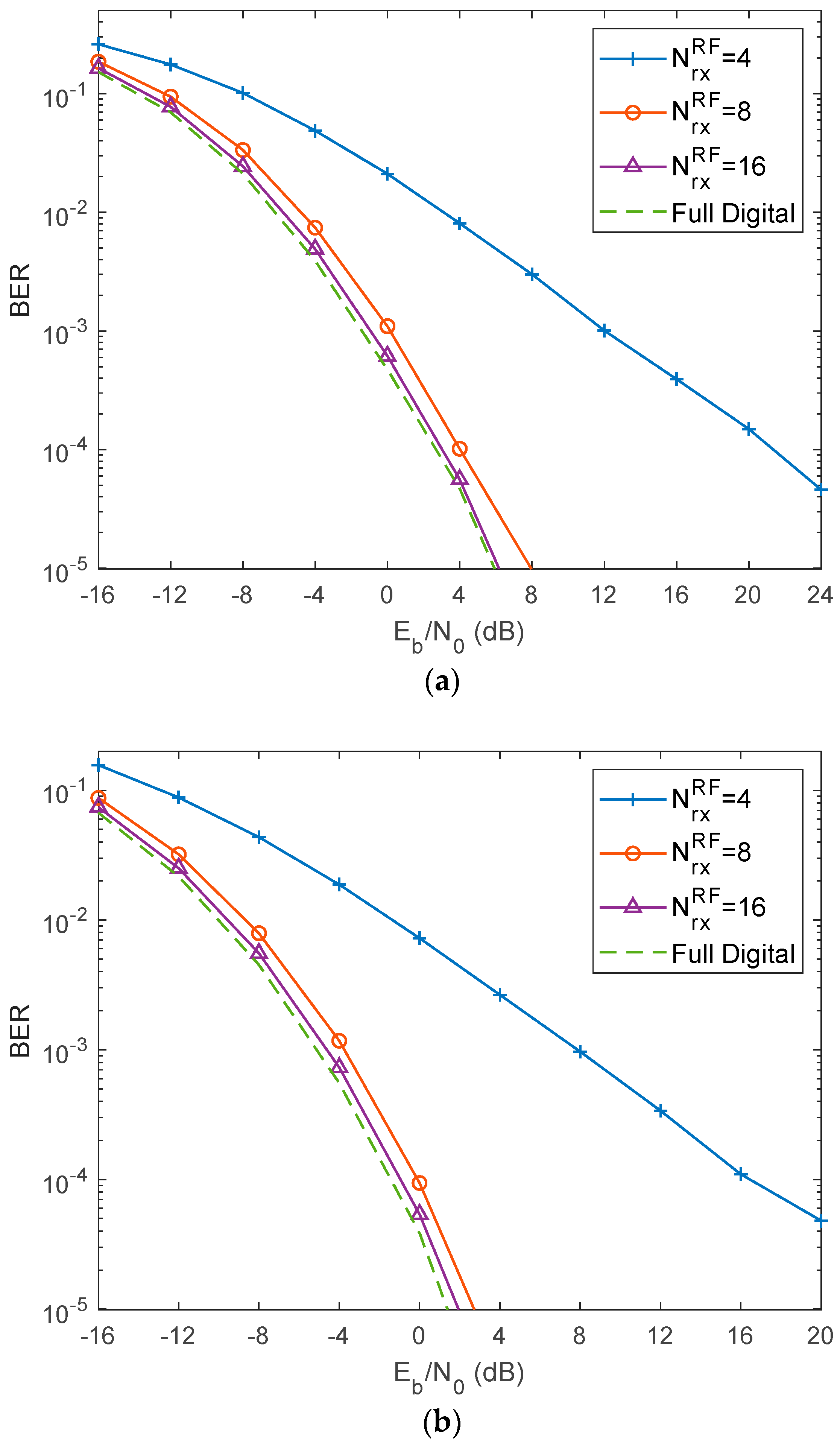
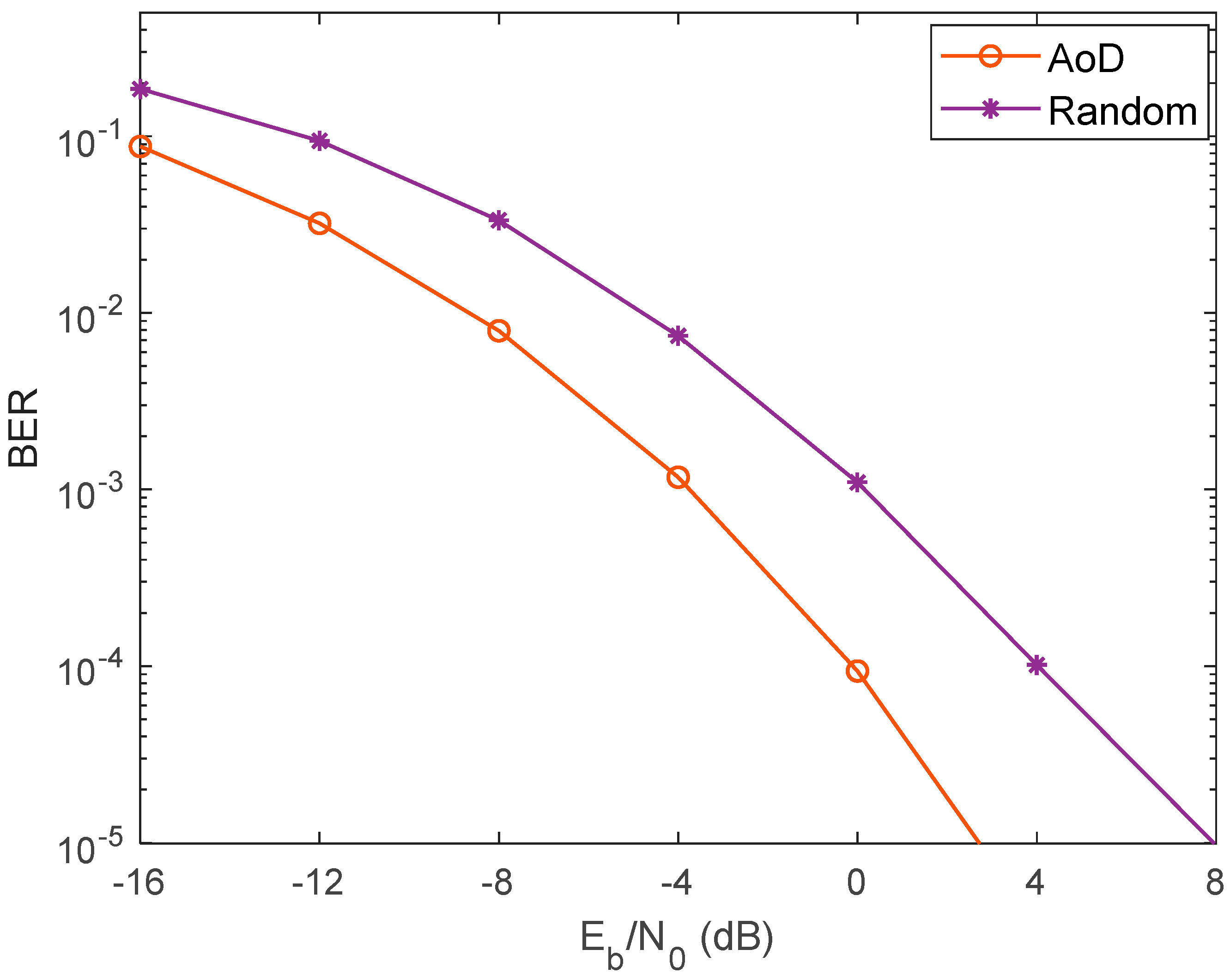
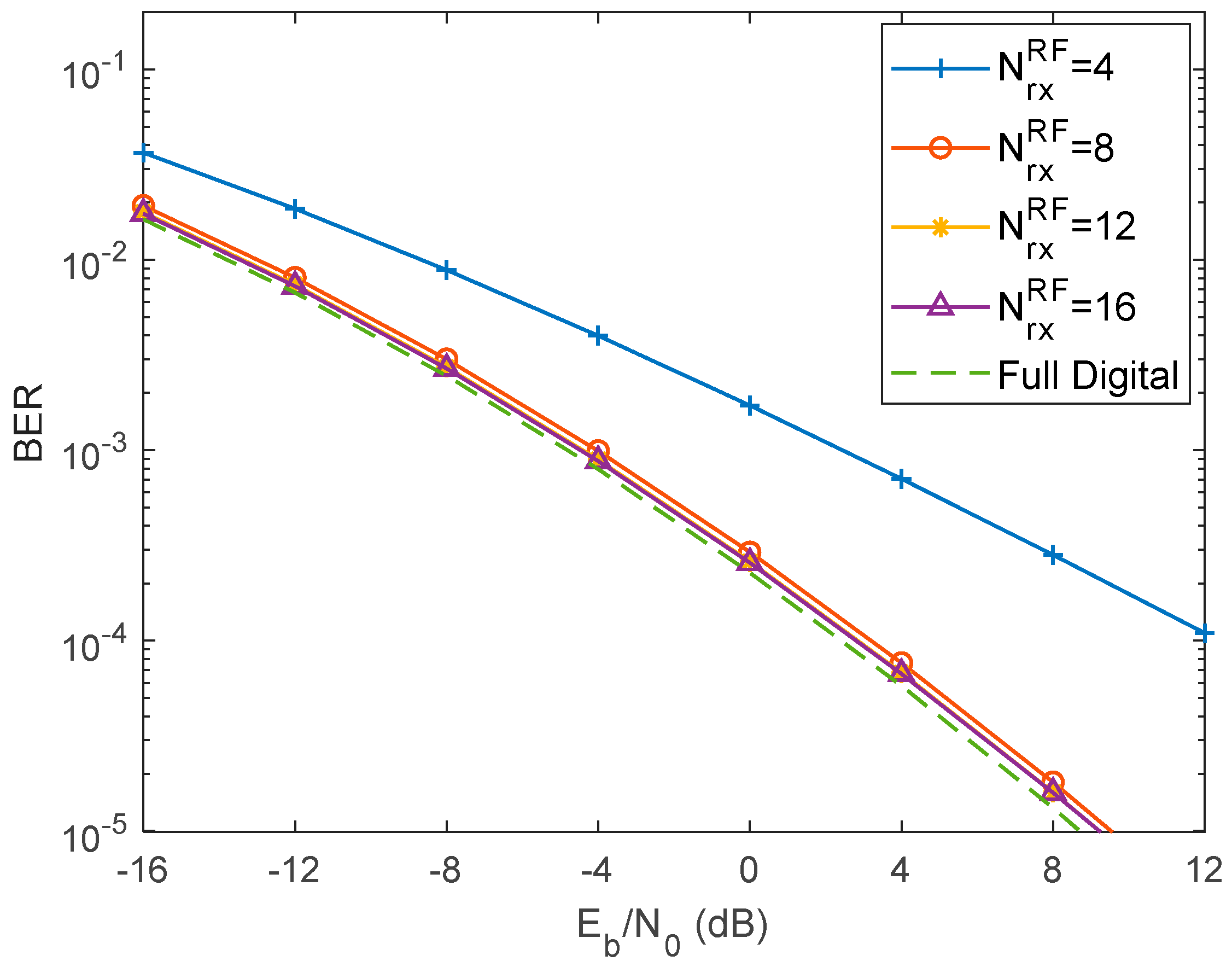
5. Performance Results

This section shows the performance of mmWave mMIMO hybrid analog-digital system using GFDM modulation. The results are evaluated through the BER ( E b / N 0 ) as a performance metric, where E b is the average bit energy and N 0 is one-sided noise power spectral density (PSD). We assume that the average E b / N 0 = σ u 2 / ( 2 σ n 2 ) = σ n 2 / 2 is the same for all users, where σ 1 2 = , = σ U 2 = 1. In this work, the used simulation parameters are depicted in Table 1.
Figure 3 shows the comparison between the proposed hybrid analog-digital scheme and the full digital one, for two types of precoders: (a) random-based precoder and (b) AoD-based precoder. Taking into consideration that the number of transmitting antennas is N t x = 8 , and the number of recieving antennas is N r x = 32 for different number of RF chains, where N r x R F = 4 , 8 , 16 , 32. For the random precoding (case (a), we can observe that the best performance among the addressed hybrid cases was when N r x R F = 16 , with a gap of only around 0.5 dB at a BER target of 10 3 compared with the full digital curve. Furthermore, it can be noticed that the gap from N r x R F = 16 to N r x R F = 8 is much lower than the gap between N r x R F = 16 and N r x R F = 4 , especially at the high SNR region. Better performance results can be depicted in case b, where AoD precoding is applied because partial CSI is available at the transmitter side. For both cases, the performance tends to the one obtained with full digital approach when the number of RF chains increases as expected.
For more illustration, Figure 4 clearly presents the enhancement in the performance of the two discussed cases, for N r x R F = 8 , where the case of partial CSI gives better results 4 dB for BER = 10 3 compared with the random precoding approach, which is expected because the information about the channels at the terminals is quite small.
Similarly, Figure 5 also compares the BER of the hybrid and the full digital schemes, for two types of precoders: (a) random-based precoder and (b) AoD-based precoder, where N t x = 16 , N r x = 64 and N r x R F = 4 , 8 , 12 , 16 , 64. Even with the increasing number of transmitting and receiving antennas, we can see from both cases, as the number of RF chains increases, the diversity order increases the performance toward the full digital curve. Nevertheless, the AoD-based precoder (case b) clarifies the enhancement of the system performance, that is, the slope will be increased owing to the diversity gain more than in the first case (a).
Figure 6 compares the BER performance of the proposed hybrid AoD-based precoder with the full digital system, in the case in which we have N t x = 16 , N r x = 128 and for different numbers of RF chains N r x R F = 4 , 8 , 16 , and 32. It can be observed from these results that increasing the number of receiving antennas gives an obvious improvement in the results, and thus the BER performance of the AoD precoder is improved, especially when the number of RF chains increases to approximately match the full digital curve.
In Figure 7, we present the semi-analytical curves for the AoD-based precoder case, with N t x = 16 and N r x = 64 , presenting results for both N r x R F = 4 and 8 . The theoretical curve totally overlaps with the simulation one when we have 8 or 12 RF chains, while there is a slight gap between the theoretical and simulated curve in the case of N r x R F = 4 .
Finally, in Figure 8, the impact of the path loss and the shadowing effects is evaluated. As we can see, the BER performance improves as the number of RF chains increases, as we saw for scenarios without path loss and showing effects. Therefore, we can draw approximately the same conclusions that we obtained before.

6. Conclusions

In this paper, we considered the design of a hybrid analog-digital MU equalizer with a simple analog precoder scheme for mmWave mMIMO GFDM-based systems. Herein, the GFDM waveform technique is proposed to overcome the high PAPR and OOB emissions of OFDM. At the transmitter, the phase shifter network is used as a simple analog precoder, where two types of precoders based on the availability of the CSI knowledge at the transmitter are used: random- and AoD-based precoder. At the receiver, a hybrid digital-analog equalizer was designed to efficiently separate users. The analog coefficients were obtained by minimizing the MSE between the hybrid structure and the full digital counterpart, noting that the GFDM structure and ZF are used in the digital part. The performance results showed that the performance gap between the hybrid equalizer and the full digital scheme decreases as the number of RF chains increases.

Author Contributions

Investigation, J.K., and M.M.; Supervision, D.C., A.S., and R.D.; Validation, P.P., A.G.; Writing—original draft, J.K., and M.M.; Writing—review & editing, R.M., D.C., A.S., and R.D. All authors have read and agreed to the published version of the manuscript.

Funding

This work is supported by FCT/MEC through national funds, under Project MASSIVE5G (PTDC/EEI-TEL/30588/2017), and by the European Regional Development Fund (FEDER), through the Competitiveness and Internationalization Operational Programme (COMPETE 2020), and Regional Operational Program of Lisbon (CENTRO 2020) - PES3N.: Soluções Energeticamente Eficientes para Redes de Sensores Seguras - POCI-01-0145-FEDER-030629.

Conflicts of Interest

The authors declare no conflict of interest.

Appendix A. Simplification from Equations (25) to (27)

From Equation (25), we can see that the minimization of the BER is equivalent to the minimization of Equation (23), which can be shown to be equivalent to minimizing the weighted difference between the hybrid and the fully digital equalizers, and whose optimality condition is W r e s , l W a = 0 , with [25]
W r e s , l = Ω d W ¯ d , l ( W a ) H E [ y l y l H ] Ω d H l H ,
where W ¯ d , l is the non-normalized digital equalizer, that is, the digital equalizer without considering the power constraint of Equation (26), and
Ω p = N M diag ( l = 0 N M 1 [ W ¯ d , l ( W a ) H H l ] ) 1 ,
E [ y l y l H ] = σ d 2 H l H l H + σ n 2 I N r x .
By applying the properties of the Frobenius norm to Equation (23), we obtain
MSE = l = 0 N M 1 tr { ( W d , l ( W a ) H H l I U ) ( W d , l ( W a ) H H l I U ) H σ d 2 + W d , l ( W a ) H ( W a ) H ( W d , l ) H σ n 2 } = l = 0 N M 1 tr { ( W d , l ( W a ) H ( σ d 2 H l H l H + σ n 2 I N r x ) ( W a ) H ( W d , l ) H ( W d , l ( W a ) H H l σ d 2 ( H l ) H ( W a ) H ( W d , l ) H σ d 2 + σ d 2 I U } .
From Equations (A3) and (A4), we can prove that
MSE = MSE ¯ + σ d 2 l = 0 N M 1 tr { I W ¯ f d , l W ¯ f d , l H } ,
with
MSE ¯ = σ d 2 l = 0 N M 1 ( W d , l ( W a ) H W ¯ f d , l ) E [ y l y l H ] 1 / 2 F 2 ,
where W ¯ f d , l denotes the non-normalized fully digital equalizer. Because minimizing MSE is equivalent to minimizing MSE ¯ , because MSE ¯ is equal to MSE , up to a constant, for an MRC approach, we can define
σ d 2 MSE ¯ ( M R C ) = l = 0 N M 1 W d , l ( W a ) H H l H F 2 ,
and we obtain the optimization problem in Equation (27).

References

  1. Yang, P.; Xiao, Y.; Xiao, M.; Li, S. 6G Wireless Communications: Vision and Potential Techniques. IEEE Netw. 2019, 33, 70–75. [Google Scholar] [CrossRef]
  2. Gao, Z.; Dai, L.; Mi, D.; Wang, Z.; Imran, M.A.; Shakir, M.Z. MmWave massive-MIMO-based wireless backhaul for the 5G ultra-dense network. IEEE Wirel. Commun. 2015, 22, 13–21. [Google Scholar] [CrossRef] [Green Version]
  3. Vu, T.K.; Liu, C.; Bennis, M.; Debbah, M.; Latva-aho, M.; Hong, C.S. Ultra-Reliable and Low Latency Communication in mmWave-Enabled Massive MIMO Networks. IEEE Commun. Lett. 2017, 21, 2041–2044. [Google Scholar] [CrossRef] [Green Version]
  4. Pi, Z.; Khan, F. A millimeter-wave massive MIMO system for next generation mobile broadband. In Proceedings of the 46th Asilomar Conference on Signals, Systems and Computers (ASILOMAR), Pacific Grove, CA, USA, 4–7 November 2012; pp. 693–698. [Google Scholar]
  5. Rappaport, T.S.; MacCartney, G.R.; Samimi, M.K.; Sun, S. Wideband Millimeter-Wave Propagation Measurements and Channel Models for Future Wireless Communication System Design. IEEE Trans. Commun. 2015, 63, 3029–3056. [Google Scholar] [CrossRef]
  6. Abdullah, N.F.; Nordin, R.; Doufexi, A.; Nix, A.R. Effect of Beamforming on mmWave Systems in Various Realistic Environments. In Proceedings of the 2017 IEEE 85th Vehicular Technology Conference (VTC Spring), Sydney, NSW, Australia, 4–7 June 2017; pp. 1–5. [Google Scholar]
  7. He, H.; Wen, C.; Jin, S. Bayesian Optimal Data Detector for Hybrid mmWave MIMO-OFDM Systems With Low-Resolution ADCs. IEEE J. Sel. Top. Signal Process. 2018, 12, 469–483. [Google Scholar] [CrossRef] [Green Version]
  8. Swindlehurst, A.L.; Ayanoglu, E.; Heydari, P.; Capolino, F. Millimeter-wave massive MIMO: The next wireless revolution? IEEE Commun. Mag. 2014, 52, 56–62. [Google Scholar] [CrossRef]
  9. Rappaport, T.S.; Shu, S.; Heath, R.W.; Nix, A.; Rangan, S. Millimeter Wave Wireless Communications; Prentice-Hall: Englewood Cliffs, NJ, USA, 2014. [Google Scholar]
  10. Heath, R.W.; Gonzlez-Prelcic, N.; Rangan, S.; Roh, W.; Sayeed, A.M. An overview of signal processing techniques for millimeter wave MIMO systems. IEEE J. Sel. Top. Signal Process. 2016, 10, 436–453. [Google Scholar] [CrossRef]
  11. Li, H.; Li, M.; Liu, Q. Hybrid Beamforming With Dynamic Subarrays and Low-Resolution PSs for mmWave MU-MISO Systems. IEEE Trans. Commun. 2020, 68, 602–614. [Google Scholar] [CrossRef] [Green Version]
  12. Grami, A. Introduction to Digital Communications; Academic Press: Cambridge, MA, USA, 2015. [Google Scholar]
  13. Mohamad, M.; Nilsson, R.; Beek, J.V.D. An analysis of out-of-band emission and in-band interference for precoded and classical OFDM systems. In Proceedings of the 21th European Wireless Conference, Budapest, Hungary, 20–22 May 2015; pp. 1–5. [Google Scholar]
  14. Michailow, N.; Matthé, M.; Gaspar, I.; Caldevilla, A.; Mendes, L.; Festag, A.; Fettweis, G. Generalized frequency division multiplexing for 5th generation cellular networks (invited paper). IEEE Trans. Commun. 2014, 62, 3045–3061. [Google Scholar] [CrossRef]
  15. El Ayach, O.; Rajagopal, S.; Abu-Surra, S.; Pi, Z.; Heath, R.W., Jr. Spatially sparse precoding in millimeter wave MIMO systems. IEEE Trans. Wirel. Commun. 2014, 13, 1499–1513. [Google Scholar] [CrossRef] [Green Version]
  16. Li, J.; Xiao, L.; Xu, X.; Zhou, S. Robust and low complexity hybrid beamforming for uplink multiuser mmWave MIMO systems. IEEE Commun. Lett. 2016, 20, 1140–1143. [Google Scholar] [CrossRef]
  17. Wang, Z.; Li, M.; Tian, X.; Liu, Q. Iterative hybrid precoder and combiner design for mmWave multiuser MIMO systems. IEEE Commun. Lett. 2017, 21, 1581–1584. [Google Scholar] [CrossRef]
  18. Ahn, Y.; Kim, T.; Lee, C. A Beam Steering Based Hybrid Precoding for MU-MIMO mmWave Systems. IEEE Commun. Lett. 2017, 21, 2726–2729. [Google Scholar] [CrossRef]
  19. Payami, S.; Ghoraishi, M.; Dianati, M.; Sellathurai, M. Hybrid Beamforming with a Reduced Number of Phase Shifters for Massive MIMO Systems. IEEE Trans. Veh. Tech. 2018, 67, 4843–4851. [Google Scholar] [CrossRef] [Green Version]
  20. Alemaishat, S.; Saraereh, O.A.; Khan, I.; Affes, S.H.; Li, X.; Lee, J.W. An Efficient Precoding Scheme for Millimeter-Wave Massive MIMO Systems. Electronics 2019, 8, 927. [Google Scholar] [CrossRef] [Green Version]
  21. Mohammed, S.L.; Alsharif, M.H.; Gharghan, S.K.; Khan, I.; Albreem, M. Robust Hybrid Beamforming Scheme for Millimeter-Wave Massive-MIMO 5G Wireless Networks. Symmetry 2019, 11, 1424. [Google Scholar] [CrossRef] [Green Version]
  22. Kolawole, O.Y.; Biswas, S.; Singh, K.; Ratnarajah, T. Transceiver Design for Energy-Efficiency Maximization in mmWave MIMO IoT Networks. IEEE Trans. Green Commun. Netw. 2020, 4, 109–123. [Google Scholar] [CrossRef]
  23. Alkhateeb, A.; Heath, R.W. Frequency Selective Hybrid Precoding for Limited Feedback Millimeter Wave Systems. IEEE Trans. Commun. 2016, 64, 1801–1818. [Google Scholar] [CrossRef] [Green Version]
  24. Kong, L.; Han, S.; Yang, C. Hybrid precoding with rate and coverage constraints for wideband massive MIMO systems. IEEE Trans. Wirel. Commun. 2018, 17, 4634–4647. [Google Scholar] [CrossRef]
  25. Magueta, R.; Castanheira, D.; Pedrosa, P.; Silva, A.; Dinis, R.; Gameiro, A. Iterative Analog-Digital Multi-User Equalizer for Wideband Millimeter Wave Massive MIMO Systems. Sensors 2020, 20, 575. [Google Scholar] [CrossRef] [Green Version]
  26. Castanheira, D.; Teodoro, S.; Simões, R.; Silva, A.; Gameiro, A. Multi-User linear equalizer and precoder scheme for hybrid sub-connected wideband systems. Electronics 2019, 8, 436. [Google Scholar] [CrossRef] [Green Version]
  27. Magueta, R.; Castanheira, D.; Silva, A.; Dinis, R.; Gameiro, A. Hybrid multi-user equalizer for massive MIMO millimeter-wave dynamic subconnected architecture. IEEE Access 2019, 7, 79017–79029. [Google Scholar] [CrossRef]
  28. Sameen, M.; Khan, A.A.; Khan, I.U.; Azim, N.; Iqbal, N. Comparative analysis of OFDM and GFDM. Int. J. Adv. Comput. Tech. Appl. (IJACTA) 2016, 4, 267–274. [Google Scholar]
  29. Kumar, A.; Magarini, M. Improved nyquist pulse shaping filters for generalized frequency division multiplexing. In Proceedings of the 2016 8th IEEE Latin-American Conference on Communications (LATINCOM), New York, NY, USA, 15–17 November 2016; pp. 1–7. [Google Scholar]
  30. Mishra, M.; Aich, S.; Kim, H.-C.; Pradhan, P.M. A novel rampbased pulse shaping filter for reducing out of band emission in 5g gfdm system. In Proceedings of the TENCON 2018-2018 IEEE Region 10 Conference, Jeju, Korea, 28–31 October 2018; IEEE: New York, NY, USA, 2018; pp. 0096–0101. [Google Scholar]
  31. Kalsotra, S.; Kumar, A.; Joshi, H.D.; Singh, A.K.; Dev, K.; Magarini, M. Impact of Pulse Shaping Design on OOB Emission and Error Probability of GFDM. In Proceedings of the IEEE 2nd 5G World Forum (5GWF), Dresden, Germany, 30 September–2 October 2019; pp. 226–231. [Google Scholar]
  32. Sim, Z.A.; Juwono, F.H.; Reine, R.; Zang, Z.; Gopal, L. Performance of GFDM Systems Using Quadratic Programming Pulse Shaping Filter Design. IEEE Access 2020, 8, 37134–37146. [Google Scholar] [CrossRef]
  33. De Almeida, I.B.F.; Mendes, L.L. Linear GFDM: A Low Out-of-band Emission Configuration for 5G Air Interface. In Proceedings of the 2018 IEEE 5G World Forum (5GWF), Silicon Valley, CA, USA, 9–11 July 2018; pp. 311–316. [Google Scholar]
  34. Gaspar, I.; Michailow, N.; Navarro, A.; Ohlmer, E.; Krone, S.; Fettweis, G. Low Complexity GFDM Receiver Based on Sparse Frequency Domain Processing. In Proceedings of the 2013 IEEE 77th Vehicular Technology Conference (VTC Spring), Dresden, Germany, 2–5 June 2013; pp. 1–6. [Google Scholar]
  35. Palomar, D.; Jiang, Y. MIMO transceiver design via majorization theory. Found. Trends Commun. Inf. Theory 2007, 3, 331–551. [Google Scholar] [CrossRef]
Figure 1. Block diagram of the user terminal (UT). FFT (fast Fourier transform), IFFT (inverse fast Fourier transform), DAC (digital to analog converter), RF (radio frequency).
Electronics 09 01220 g001
Figure 2. Block diagram of the receiver. ADC (analog to digital converter).
Electronics 09 01220 g002
Figure 3. Performance comparison of the proposed hybrid precoders with the full digital system for N t x = 8 and N r x = 32 : (a) random-based precoder, (b) angle of departure (AoD)-based precoder.
Electronics 09 01220 g003
Figure 4. Performance comparison of the proposed hybrid AoD- and random-based precoder, for N t x = 8 and N r x = 32 when N r x R F = 8 . BER, bit error rate.
Electronics 09 01220 g004
Figure 5. Performance comparison of the proposed hybrid precoders with the full digital system for N t x = 16 , and N r x = 64 : (a) random-based precoder, (b) AoD-based precoder.
Electronics 09 01220 g005aElectronics 09 01220 g005b
Figure 6. Performance comparison of the proposed hybrid AoD-based precoder with the full digital system for N t x = 16 and N r x = 128 .
Electronics 09 01220 g006
Figure 7. Performance comparison of the proposed hybrid AoD-based precoder between theoretical and simulation cases for N t x = 16 and N r x = 64 .
Electronics 09 01220 g007
Figure 8. Performance comparison of the proposed hybrid AoD-based precoder after applying the shadowing effect.
Electronics 09 01220 g008
Table 1. Simulation parameters. GFDM, generalized frequency division multiplexing; ULA, uniform linear array.
ParametersValue
Modulation typeGFDM
Number of subcarriers K = 64
Number of timeslots M = 15
Oversampling factor L = 1
Samples per symbol N = 64
Number of users U = 4
Transmitting antennas N t x = 8 or   16
Receiving antennas N r x = 32 , 64 or 128
Channel model parametersArray configurationULA
Time in samples where the channel rays has a significant power D = N M / 4 = 240
Carrier frequency f c = 72 GHz
Antenna element spacing δ = λ / 2
Number of clusters N c l = 4
Number of rays per cluster N r a y = 5
Angle spread for the transmitter and receiver σ ϕ q r x = σ ϕ q t x = 10 º
Decay from the first to the last channel cluster β 0 , N c l 1 = 10 dB
Decay from the first to the last ray of each channel cluster β q , 0 , N r a y 1 = 10 dB , q = 0 , , N c l 1

