1. Introduction
The demand to increase data communication rates leads to an increase in used frequencies, as seen in the development of the fifth generation (5G) of cellular communications, which uses millimeter waves (MMW) (30–300 GHz) for indoor, short-range links, and outdoor point to point links. The nature of wave propagation in MMW radiation is approximately like the ray-tracing model. It is affected by atmospheric conditions, specular reflections and multi-path, and directivity of transmitters and receivers [
1]. Implementing tuning reflectors for the 5G wireless communication allows a quasi-line of sight paths and improves the link. In outdoor communication, it requires bypassing obstacles such as buildings and other constructions in urban areas or mountains, and more, in non-urban areas [
2,
3,
4]. In indoor communication, it requires tunable reflectors to bypass walls and turns [
5].
In addition, the implementation of 5G cellular communication requires tracking the user’s location continuously and directing the MMW beam correctly. The tracking procedure is carried out nowadays using the existed 4G network. Knowing the exact user’s location enables the base station to find the best trajectory using tunable reflectors, between the base station and the user [
6].
However, low-cost, low profiles, reduced masses, remote-controlled, and efficient solutions are required due to the network density and the number of components. A metasurface (MS) solution, which can be programmed remotely by the base station to bring the beam optimally to the user with low weight, low complexity, and low cost, is offered in this work.
Metasurfaces (MSs), and especially reconfigurable MSs, arouse great interest in science. There are many interdisciplinary applications where MSs play an important role [
7]. For example, a millimeter-wave MS perfect absorber was designed to detect micro-poisons in drinking water [
8], and a flat parabolic surface was used in W-band imaging and beam propagation [
9]. These MSs are based on resonant unit cells and are limited to a narrow bandwidth around a fixed working frequency. Adding tunability to each unit cell enables a reconfigurable MS and expands the abilities and options of MS applications. Integrated electronic devices or tunable materials achieve the reconfigurability to the MS. For example, PIN switches, MEMS switches, liquid crystal or piezoelectric materials, and varactor diodes [
10,
11]. Using the switches, it becomes possible to connect and disconnect conductive elements on the unit cell, or between unit cells on the surface, thereby changing the electrical properties of the surface. Switches are conveniently integrated into standard PCB circuits. The PIN switch enables MS applications of up to 60 GHz [
12], with fast switching time, high reliability, low cost, and low control voltage switches [
10,
13]. Recently, the MEMS switch arouses attention due to its small size and linearity, but it has a relatively slow switching time, compared to the pin switch [
14]. The discrete nature of switches prevents their use in applications where a continuous phase change is required. Liquid crystal changes the dielectric coefficient of a unit cell by tens of percent and can be realized in the surface without any external element in the front. This method is more difficult to implement and can be used at K-band and above [
15]. However, it has a slow response time compared to switches and varactors [
16]. The piezoelectric method allows limited flexibility proportional to the change in its physical size, which is also its obvious drawback [
11]. The varactor diodes allow continuous and high tuning ratio capacitance, constant Gamma for linear tuning, a convenient PCB assembly, and very low consuming power [
17].
Reconfigurable MSs were implemented for various applications, such as: reconfigurable reflect arrays [
10,
18,
19], reconfigurable antennae [
20], leaky-wave antennae [
21], tunable filters and absorbers [
22], parabolic mirrors with a controlled focus [
23], and tuning polarization rotators [
24]. Reconfigurable MSs based on varactor diodes were realized at X-band and below [
21,
22,
23,
24,
25,
26,
27,
28]. For Ku-band frequencies, only simulation works have been published [
29,
30]. Adjusting the MS component by developing appropriate unit cells for the new, used frequencies is required.
However, manufacturing MS at higher frequencies bands such as K-band and Ka-band requires a decrease in unit cell dimensions. Thus, the varactor size becomes a significant part of the front MS area causing more absorption and diffusion. Design and consideration of a new reconfigurable MS reflector at K-band are presented and simulated. This MS reflector allows a simultaneous independent 2-D continuous steering ability of the reflection radiation and is suitable for indoor and outdoor 5G communication methods, to overcome obstacles such as buildings, walls, and turns. Using the continuous reflection phase method compared to the discrete reflection phase method, when using switches, allows avoiding beam steering quantization loss, of up to 3 dB [
18]. To the best of our knowledge, such a 2-D continuous tunable MS for K-band frequencies has neither been demonstrated nor published. The paper is organized as follows.
Section 2 describes the general resonant MS unit cell principles and parameters based on effective impedance surface model.
Section 3 introduces the steering MS refractor mathematical method, based on the phased array theory.
Section 4 describes the unit cell and MS design principles and considerations.
Section 5 presents simulations results and analyzes the unit cell reflection and the dynamic reflection phase range.
Section 6 presents the reconfigurable MS reflector steering simulations results in 1-D and 2-D.
Section 7 concludes this paper.
2. Effective Impedance Surface Model of Unit Cells Array
Reflective MSs are based on resonance unit cells, which are smaller than the working radiation wavelength. A basic equivalent unit cell circuit is a parallel resonance circuit. When the unit cells are arranged in a 2-D periodic form, the MSs are characterized by effective impedance surface [
25] and are shown in Equation (1):
where
L is the inductance and
C is the total capacitance of each unit cell. The values of
C and
L are determined by the unit cell geometry, materials, varactor parameters, and PCB properties. The parallel resonance frequency
fres of the circuit model is shown in Equation (2)
The bandwidth of the resonance frequency [
31] is shown in Equation (3)
where
R is the dissipation resistive part of the unit cell. This kind of surface is also known as High Impedance Surface (HIS) [
32] or Perfect Magnetic Conductor (PMC) [
33]. For a resonance frequency, this surface reflects incident radiation at 0° phase in contrast to a normal metal surface, which reflects the radiation at 180° phase. The reflection phase changes around
fres. Far below the
fres, the surface reflects with a phase shift of 180°, like a metal surface, and approaches −180° for frequencies far above resonance, when for a wide
BW, the change moderates and vice versa. Varactor diodes inserted into the unit cell provide variable capacitance
Cd to enable tunability [
25,
26,
27,
28,
29,
30]. The unit cell reflection phase value around the resonance frequency changes significantly. Thus, changing the
fres around the working frequency changes the reflection phase.
Controlling the phase of each unit cell in the surface allows the design of spatial phase distribution, which leads to steer reflection radiation to the desired angle [
25]. This approach is well known in the literature, as mentioned above, but MS-based varactor diodes are demonstrated only in Ku-band and below. However, MS realization at higher frequency bands such as K-band and Ka-band requires decreasing product
LC in Equation (2) to achieve higher
fres. In the MS resonant unit cell, surface area size is proportional to intrinsic capacitance
Cint, and thickness is proportional to intrinsic inductance
Lint [
34]. Considering
Cd as a method of tuning,
C =
Cint + Cd, and
L =
Lint in Equations (2) and (3). Reducing unit cell dimensions leads to production difficulty and challenge. The reduction in
L in the
LC product in Equation (2) is limited since it decreases bandwidth and increases the sensitivity to phase errors according to Equation (3). In addition, since the
Q factor is
Q = 1/BW and total absorption is
R ×
Q [
34], decreasing
C in Equation (2) reduces
Q factor value, which reduces unit cell absorption. Thus, in decreasing product
LC, the emphasis is
C reduction, which requires careful design since it is accompanied by reducing the unit cell area. Thus, the varactor size becomes a significant part of the front MS area, causing more absorption and diffusion. The proposed simple, inexpensive, and innovative unit cell has a low intrinsic capacitance
Cint, which, along with using a small-size varactor with the lowest capacitance available on the market today [
17], enables MS realization for Ka-band with reasonable dimensions, allowing conventional PCB manufacturing and varactor assembly.
3. Mathematical Method of Steering MS Refractor
According to the phased array theory, each unit cell location on the MS is defined at its center [
35]. A 2-D surface on XY plane with spatial array arrangement of a fixed distance and a 90° angle between the unit cells is defined as S (x
j, y
i), j = 1, 2, M and i = 1, 2, N when N and M are an integer leads to an array of N × M elements. The MS reflector side cross-section view scheme is described in
Figure 1.
Figure 1 shows a reconfigurable MS reflector scheme. L
1, L
2, and L
N are incident rays towards the surface. Due to a planned gradual phase provided by the unit cells MS reflector, the rays are reflected at the desired angle
θ. The optical path difference (OPD) between the cells is defined as Δ
L [
9] and is shown in Equation (4)
where Δ
X is the array constant. The conversion of OPD into phase difference is shown in Equation (5)
A gradual accumulating phase by supplying a phase difference Δ
φx, between adjacent unit cells X
(j) and X
(j+1) in
axis, yields to the desired steering angle
θ in XZ plane. Using Equations (4) and (5), the connection between Δ
φx and Δ
x to the desired angle steering
θ is shown in Equation (6)
For steering angle θ in the YZ plane, the same analysis in axis is valid using Δφy and Δy in Equations (4)–(6). A combination of independent steering in planes XZ and YZ results in 2-D steering ability. Those MS properties are frequency-sensitive, allowing us to steer the reflection direction of an incident beam in a limited frequency band.
4. Unit Cell and MS Reflector Design
The unit cell design and its equivalent circuit model are shown in
Figure 2.
The front-side, backside, profile, and 3-D inside view of two adjacent unit cells are shown in
Figure 2a–d, and the unit cell equivalent circuit model is shown in
Figure 2e. The unit cell is composed of two similar dielectric substrates of Rogers Company, model RT/Duroid 5880 with
εr = 2.2 [
36], and three copper layers of 35-micrometer thickness. There are two vertical strips in the top layer, each connected to a pad, according to the varactor layout [
17]. One of the vertical strips is the same length of the unit cell width—
W. The second strip is shorter—
SL—and is connected by the via to the circle pad in the lower copper layer, which functions as the DC bias layer. The middle copper layer is for metal ground purposes and separated by clearance from the via which crosses it (see
Figure 2d). In a single unit cell, there is a small violation of the
axis symmetry, resulting from the use of one via and the different strip lengths. The right unit cell on the
axis is a mirror image of the left unit cell, such that symmetric array is obtained (see
Figure 2a–d).
Cint is governed by the radiation electric field component’s interaction, with the unit cell strips edges.
Cint is inversely proportional to the distance between the strip’s edges
D [
37], as described in Equation (7)
where
SW is the strip width. The length
P of the unit cell is larger than the width
W and allows the strips to be positioned such that
Do, and
Di lead to low intrinsic capacitance (see
Figure 2a). According to Equation (7), the calculated capacitances contributions of the strip’s edges are 0.0451 pF and 0.0503 pF for
Di = 0.9 mm and
Do = 0.6 mm, respectively, and sum up to
Cint = 0.0954 pF. Thus, the capacitance and coupling between adjacent unit cells decrease. This geometry enables operation at Ka-band frequencies, with sufficient surface area for the varactor integration, preventing significant absorbing and diffusing. The reduction in
Sw increases the distance between the strips and decreases
Cint but also increases unit cell losses, and therefore is limited. Furthermore, it distorts the uniformity of the electric field distribution on the unit cell and decreases bandwidth [
25].
MACOM varactor diode model MAVR–011020–1411 [
17] is used in this MS, which provides extremely low capacitance. The varactor is placed between the strips (see
Figure 2 in green), adding variable capacitance
Cd to the unit cell. The dynamic range of the capacitance
Cd is
Cmax = 0.216 pF to
Cmin = 0.032 pF for 0–15 V reverse bias voltage, respectively. The package capacitance is included in
Cd and provides a capacitance ratio of 7 [
17]. The MS reflector structure with the DC bias scheme is shown in
Figure 3.
The MS structure and the simple DC bias method of this geometry, which reduces the complexity and absorption of the unit cell, are shown in
Figure 3, where the red dashed rectangles mark the location of a specific two adjacent unit cell. The via and the clearance add losses to the unit cell and are a constraint due to the need to provide DC voltages for each varactor. The longer strip in each unit cell is connected to other unit cell’s longer strips throughout the column. These strips function as a common DC ground for the varactors in each column, without the need for an additional via in each unit cell. The shorter strip receives a separate DC voltage from the back of the surface using the via, allowing each MS unit cell to be independently configurable (see
Figure 3). The phase reflection is independently manipulated in 2-D, compared to [
25], in which the varactors are between the adjacent unit cells, and each unit cell receives only a DC ground or a specific DC voltage. Thus, a constraint is created for the capacitance value between each unit cell and the four unit cells around it. This limitation does not allow the reflection phase to be independently configurable in 2-D. This is an improvement of our previous experimental work, which demonstrated beam steering in 1-D at the working frequencies of 21–23.5 GHz [
38]. In this work, a simultaneous and independent 2-D beam steering is presented at a higher working frequency of 37 GHz, for the incident polarization, which is shown in
Figure 3a.
Considerations in selecting the materials and determining the unit cell’s parameters values are described as follows: the selected RT/Duroid 5880 dielectric substrate has a low
εr = 2.2, which supports the need to reduce the
Cint, according to Equation (7). The substrate thickness is proportional to
L [
34]. Thus, increasing the substrate thickness increases
BW and vice versa, according to Equation (2). The losses are in accordance with the
Q factor, which is inversely proportional to
BW; thus, decreasing the substrate thickness leads to an increase in the acquired dynamic range and higher losses at the working frequency. For the presented unit cell geometry, two commercial dielectric substrate thicknesses of 0.127 and 0.381 mm were simulated. Low losses of 2.17 dB were obtained at the working frequency of 37 GHz for a substrate thickness of 0.381 mm, but with low dynamic phase range of only 256°. A high dynamic phase range of 323° was obtained at the working frequency of 37 GHz for a substrate thickness of 0.254 mm, but with a loss of 7.35 dB. Optimization was performed for a substrate thickness of 0.254 mm, to achieve the targets of a loss lower than 5 dB and a dynamic phase range higher than 300°, at the working frequency of 37. Using 3-D electromagnetic simulation software, CST [
39], the unit cell parameters of the simulations were swept with emphasis on W and
Sw. The final optimized parameters, which are in accordance with the design principles, and suitable to standard PCB manufacturing, are summarized in
Table 1.
5. Simulations Results and Analysis of Unit Cell Reflection and Dynamic Phase Range
The proposed MS reflector was simulated using the TEM Floquet port with CST simulation software [
39]. The reflection simulation of a unit cell as an infinite array for the normal incident corresponds to the polarization described in
Figure 2a, as shown in
Figure 4.
The simulation results of the unit cell magnitude and phase reflection are shown in
Figure 4 as a function of frequency, for the following three capacitance values: C
d min = 0.032 pF, C
d max = 0.216 pF and C
d (37 GHz) = 0.065 pF, which is the varactor capacitance value that leads to the unit cell resonance frequency at 37 GHz. The unit cell resonance frequency is electronically changed from 30.3 to 43.1 GHz. It provides a dynamic reflection phase range of up to 303° and over 300° in wide bandwidth of over 4 GHz, marked between the dashed black crossers at 33.25 and 37.55 GHz, as shown in
Figure 4b.
The unit cell equivalent circuit model with all the inherent parameters is shown in
Figure 2e [
7]. The total unit cell resistance R influences only the absorption losses intensity and is composed of R
diel from dielectric losses, R
ohm from ohmic losses, R
s from varactor serial resistance, and another resistance component R
p from inaccuracies and parasitics in production. While R
diel and R
ohm are well defined and quantified in CST simulation, the R
s value is unknown, and the R
p value depends on the production quality and not on unit cell inherent properties. Based on similar studies [
40,
41], and an accurate qualitative production assumption, the equivalent value of R
s and R
p in the simulations was determined as 4 Ω.
In this study, careful design and analysis are required due to very small capacities in this unit cell, mainly around C
d = C
min. The varactor physical presence and its contact with the pads (see
Figure 2) add parasitic capacitance to the unit cell and should be taken into consideration due to the low C
int and
Cd in this realization. We define it as the second-order parasitic capacitance
C2ndp. This value is influenced by the varactor environment and the varactor effective dielectric constant ε
eff, which depends on the varactor material.
C2ndp is modeled in CST simulation as a rectangular dielectric slab of the varactor size with estimated value off
εeff, as shown in green in
Figure 2a–d. The dielectric values of the varactor compounds are silicon nitride—7.65 [
42], polyimide—3.44, and gallium arsenide—12.9 (the values from the CST library). The value
εeff = 6, which is around the middle of the extreme value and is set for the rectangular dielectric slab. According to the CST simulation,
C2ndp = 0.008 pF, a value which is usually negligible but needs to be considered in this work because of the very low total capacitance. The unit cell dynamic capacitance range is shown in Equation (8)
where
C is between 0.1354 and 0.3194 pF. Plugging C for different cases of
Cd in (2) shows good agreement in the
fres tuning simulations results, as shown in
Figure 4. The reduction in
Cint, combined with the chosen varactor, leads to a high capacitance ratio and allows wide tunability.
Gradual linear accumulated reflected phases throughout the MS reflector with uniform reflected intensities are required to achieve the desired steering angle θ described in (6). In practice, impurity in the intensity causes a minor change in θ, due to different losses in the MS reflector unit cells. The continuous tuning ability of each unit cell allows using error correction algorithms for improved results and accuracy. The maximum loss value is 4.37 dB for unit cells in the MS with a resonance frequency of 37 GHz, as shown in
Figure 4a (middle red line). Losses of unit cells with higher or lower resonance frequency are less than 4.37 dB at 37 GHz with a negligible value for unit cells with resonance frequencies, which relate to
Cd max and
Cd min. This phenomenon of losses is unavoidable due to the nature of resonance element usage, but is minimized by using low loss materials and proper unit cell design, such as decreasing Q factor.
Sweeping the above unit cell reflection phase simulations versus varactor capacitance
Cd at specific work frequency 37 GHz leads to the dynamic phase range as shown in
Figure 5.
Figure 5 shows the whole dynamic phase range of unit cell reflection phase at 37 GHz as a function of C
d, for a normal incident (in black line) and off-normal incidents (in red dashed and blue dotted-dashed lines). The DC bias for each unit cell is determined based on the calibration curve in
Figure 5, such that the ΔC
x between adjacent unit cells in the
axis provides the desired Δφ
x, and the ΔC
y between adjacent unit cells in the
axis provides the desired Δφ
y, as seen in
Figure 3a. Phase values were normalized between 0° and 360° with a value of 0° for C
d max, and 303° for C
d min and allow MS spatial phase distribution value of 303° out of the ideal value of 360°, where the dynamic phase is used in a cyclic manner. For high steering θ, which requires Δφ ≥ 57° according to (6) or for large size MS, which requires the usage of more than 303° available range, the range part of 57° leads to a phase error. The fundamental array constant Δx =
P or Δy =
W can be doubled to reduce the influence of the missing phase range on Δφ in (6). This doubling increases the effective array constant parameters and compensates over the limitation in Δφ values. The multiplication of array constants Δx and Δy is achieved by applying the same DC voltage/capacitance value to adjacent unit cells in the
or the
axis, respectively, as seen in
Figure 3a,b. The array constants Δx and Δy can also be multiplied further where a higher value leads to exceeding the MS definition, where unit cell dimensions are smaller than the working wavelength. Alternatively, any steering can be achieved without multiplying Δx or Δy with performance degradation due to phase mismatch [
43]. For small-sized MS, Δφ can be used without limitation, as long as it is used in one dynamic phase range cycle. This is a typical limitation of MS reflector, which is seen in other lower frequency studies of different geometries [
25,
29,
30].
6. Reconfigurable MS Reflector Steering Results
The final MS reflector is a fixed 2-D array size that was designed and simulated based on the above unit cell reflection results. The array size is 75.2 mm × 188 mm with 12 rows and 8 columns of unit cells, which sum up to 96-unit cells, and can be stimulated with separate DC voltages as needed. MS reflector with the axes steering definition and an example of a 3-D far-field reflection result, without phase manipulation, are shown in
Figure 6.
For azimuth steering (−), every unit cell in each column is connected to the same DC voltage/capacitance value, to achieve the desired Δφx while Δφy = 0, and for elevation steering (), every unit cell in each row gets the same DC voltage/capacitance value, to achieve the desired Δφy while Δφx = 0.
For 1-D steering mode, considering the dynamic phase range and MS size, the phase difference parameter—Δ
φx or Δ
φy—is limited, as shown in Equation (9)
For azimuth and elevation 1–D steering, several θ angles were calculated using (6) and simulated using CST for normal incident TEM plan wave around 37 GHz, which corresponds to the polarization described in
Figure 6. The simulation results are shown in
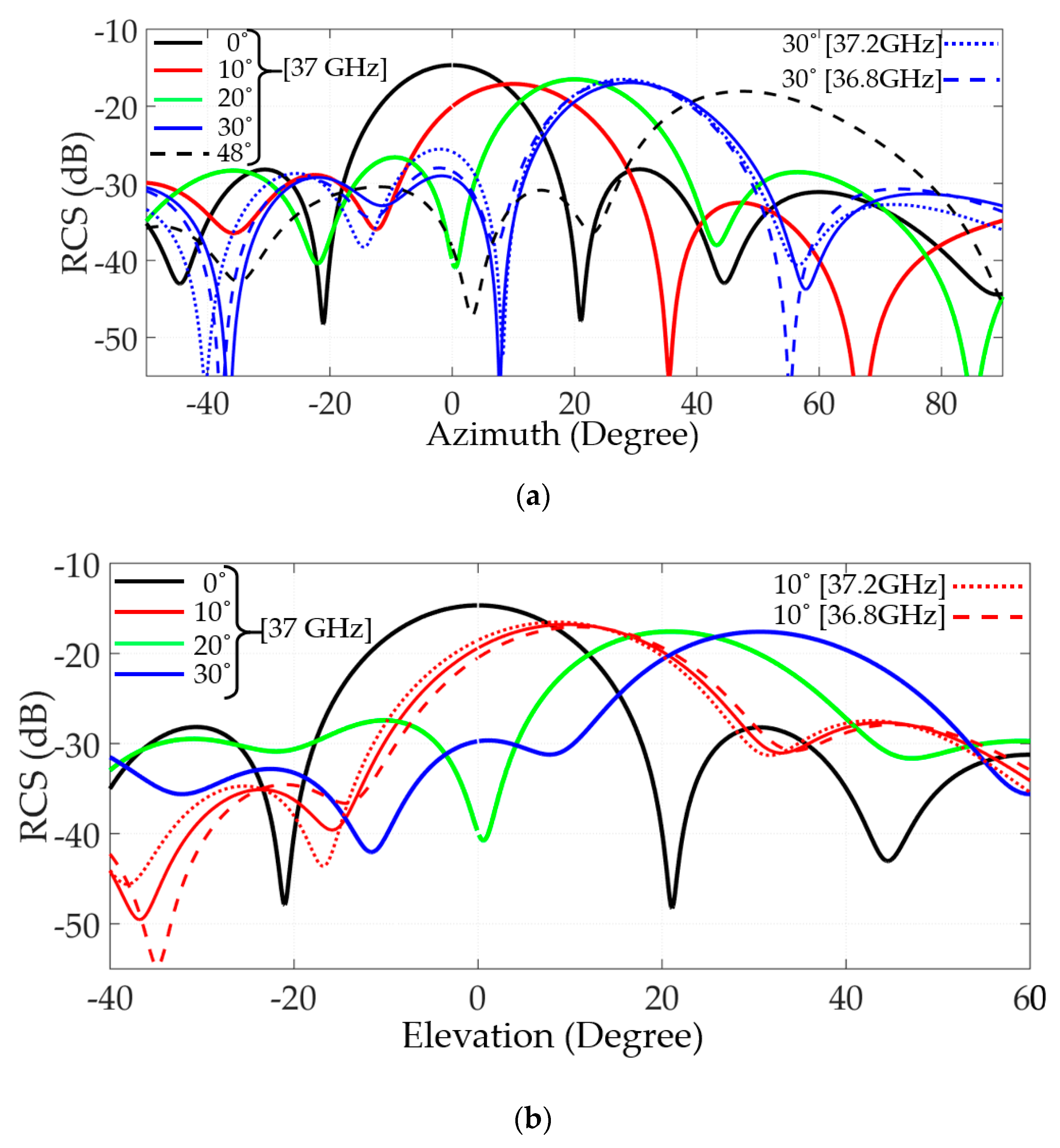
Figure 7.
Steering angles simulations results of 10°, 20°, 30°, and 48° in azimuth and 10°, 20°, and 30° in elevation compared to reference result at 0° are shown in
Figure 7a,b, respectively.
Deviation for ± 200MHz around 37 GHz for the same TEM incident wave for steering angle 30° in azimuth and 10° in elevation is shown in
Figure 7 (dotted and dashed lines). The results show overlap within frequency deviations, which leads to a bandwidth of about 400 MHz.
Table 2 and
Table 3 summarize the parameters in Equation (6) for calculating the steering angles shown in
Figure 7.
In 2-D steering mode, considering the dynamic phase range and MS size, the phase difference parameters,
and
, are limited, as shown in Equation (10)
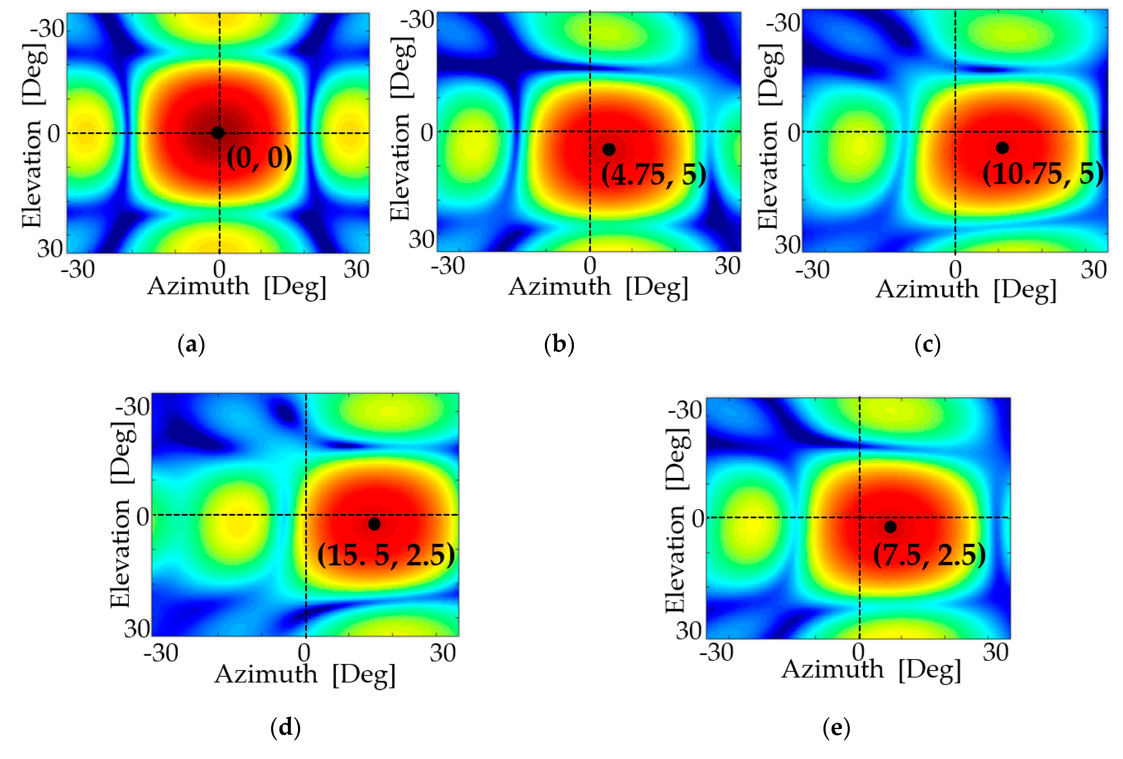
In order to serve an angular spatial cone of 20° and 10°, steering abilities of ± 10° in azimuth and ± 5° in elevation are required and lead to maximum values of Δφx = 20.83° and Δφy = 6°, respectively. The total sum of MS phase distribution in use is 211.81°, which is smaller than 303° and meets the definition in Equation (10). In order to serve an angular spatial cone of 30° and 5°, steering abilities of ± 15° in azimuth and ± 2.5° in elevation are required and lead to maximum values of Δφx = 31.05° and Δφy = 3.3°, respectively. The total sum of MS phase distribution in use is 253.65°, which also meets the definition in (10).
Figure 7 shows the simulation results of the dynamic phase range for off-normal incident radiation, which comes from the above spatial cone example’s edges compared to the simulation results for a normal incident case. The simulation results coincide. Thus, a reasonable spatial cone can be supported and covered by the MS reflector. Two-dimensional steering simulation results at 37 GHz for the angular partial cone edges mentioned cases are shown in
Figure 8.
Following the discussion in paragraph 5, the use of Equation (6) in the case of non-uniformed intensities, due to different losses in MS reflector unit cells, leads to a small gap between the simulated steering angles θ, shown in
Figure 8, compared to the calculated steering angles θ, summarized in
Table 4. This gap can be corrected by a slight change in the phase difference parameters—
and
—used in Equation (6). Due to MS reflector symmetry, the same steering results in 1-D and 2-D can be obtained in the opposite direction, by inversing the capacitance and phase distribution gradient. Comparison between continuous tunable MS reflector works with a varactor as a tuning method is presented in
Table 5.


