Underwater Network Management System in Internet of Underwater Things: Open Challenges, Benefits, and Feasible Solution

 ,
,
Abstract
1. Introduction
- Overview of U-NMS based on acoustic communication technology in IoUT.
- Identify and outline the open challenges of NMS in IoUT and illustrate the benefits of U-NMS.
- Core FCAPSC functions of U-NMS in IoUT.
- The comparative analysis of the network management and device management protocols of IoT, along with the U-NMS.
- Requirements supporting U-NMS in IoUT.
- Propose a unique prototype design for U-NMS in a laboratory environment for IoUT, using acoustic communication technology.
2. Background
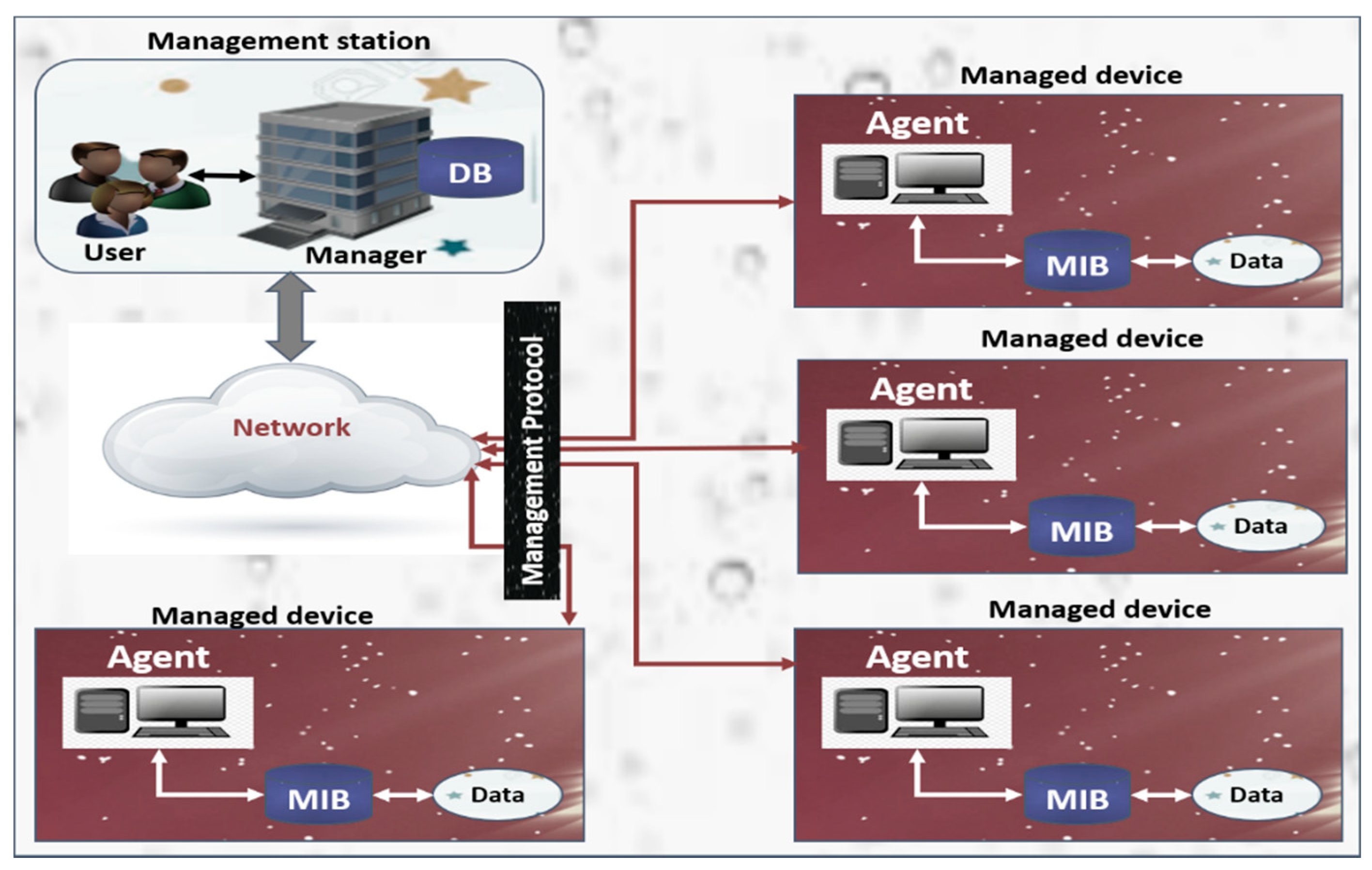
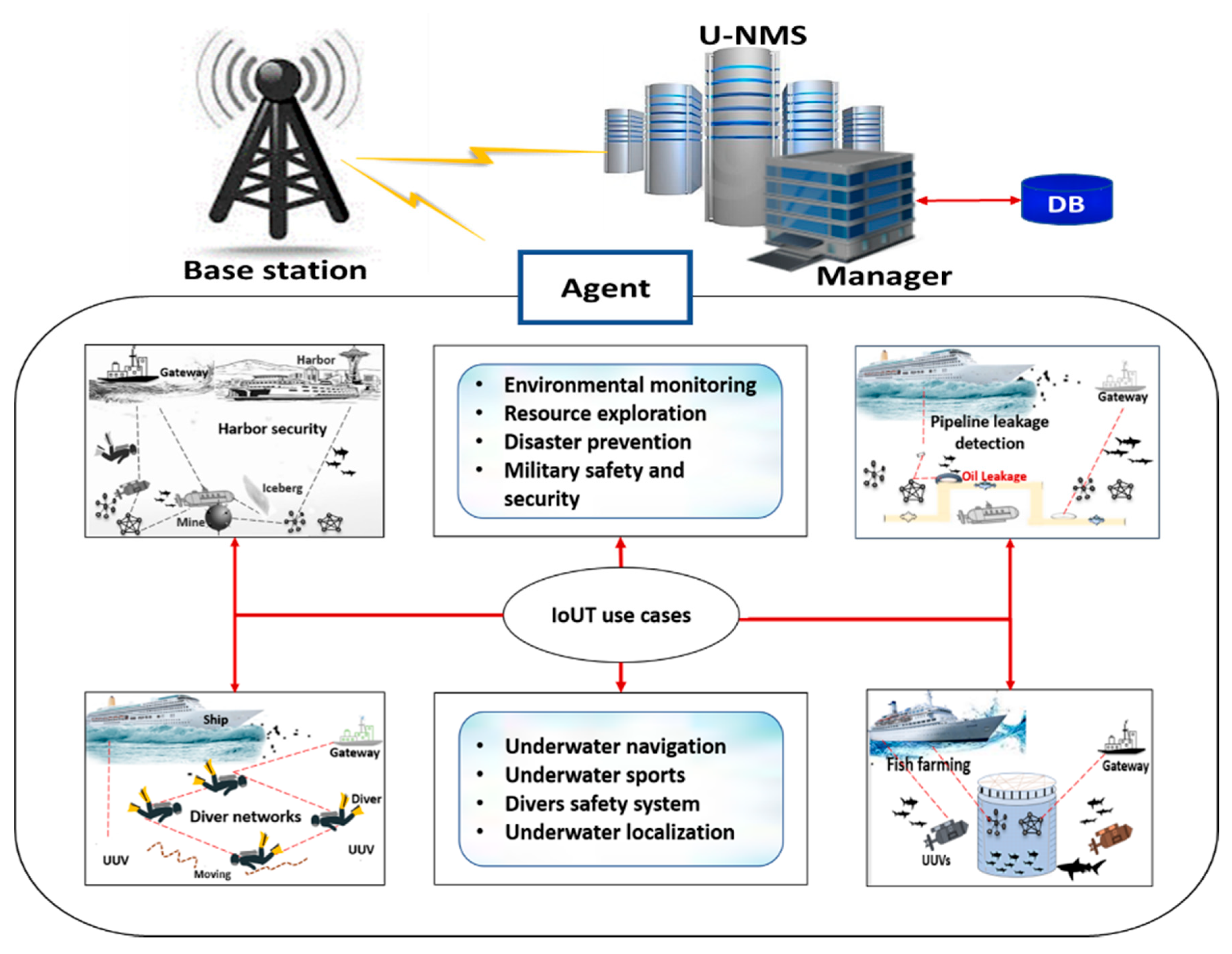
2.1. Overview of U-NMS
- Intelligence: This is concerned with merging algorithms, as well as computation, along with hardware plus software, which makes it smart enough to interact with various underwater and surface devices in an efficient manner.
- Connectivity: Connectivity aids in network availability and compatibility.
- Sensing: The main function of underwater IoT is sensing, which enables sensors in detecting any changes in the underwater environment and reporting the status or communicate with the matching environment.
- Energy: For the intelligent power ecosystem that is made for underwater IoT, the essential parts such as Energy harvesting, charging infrastructure, and power efficiency must be present.
- Security: Securing the devices, networks, and data transmission comprise a very important part of underwater IoT.
- Node mobility: Due to the constrained underwater environment, there is no permanent location of the sensor nodes present under sea level in the underwater wireless sensor network. The nodes are mobile, which results in improper communication.
- Time synchronization: Time synchronization is an essential yet challenging problem in underwater sensor networks (UWSNs). This challenge can be ascribed to (1) messaging timestamping, (2) node mobility; and, (3) the Doppler scale effect.
- Multi-path effect: The internal stratification of the ocean causes multi-path effects such as distortion and severe frequency-dependent fades. A multi-path medium results in a temporal spread of the transmitted pulses, as well as time-variant propagation delays and attenuation factors.
- Stratification effect: Localization is one of the essential tasks for underwater acoustic sensor networks (UASNs). The sound speed in water environments varies with depth; therefore, the sound waves do not propagate along a straight line. This phenomenon is described as the stratification effect.
- Underwater noises: Various noises underwater, such as ship noise, bio noise, wind noise, rain noise, etc. can make considerable changes in data underwater data transferrer.
- Heterogeneity: The major design requirements for IoUT include scalability, modularity, extensibility, and interoperability.
- Dynamic Changes: Various IoUT devices state alters dynamically according to the environment, and the system should catch up with these.
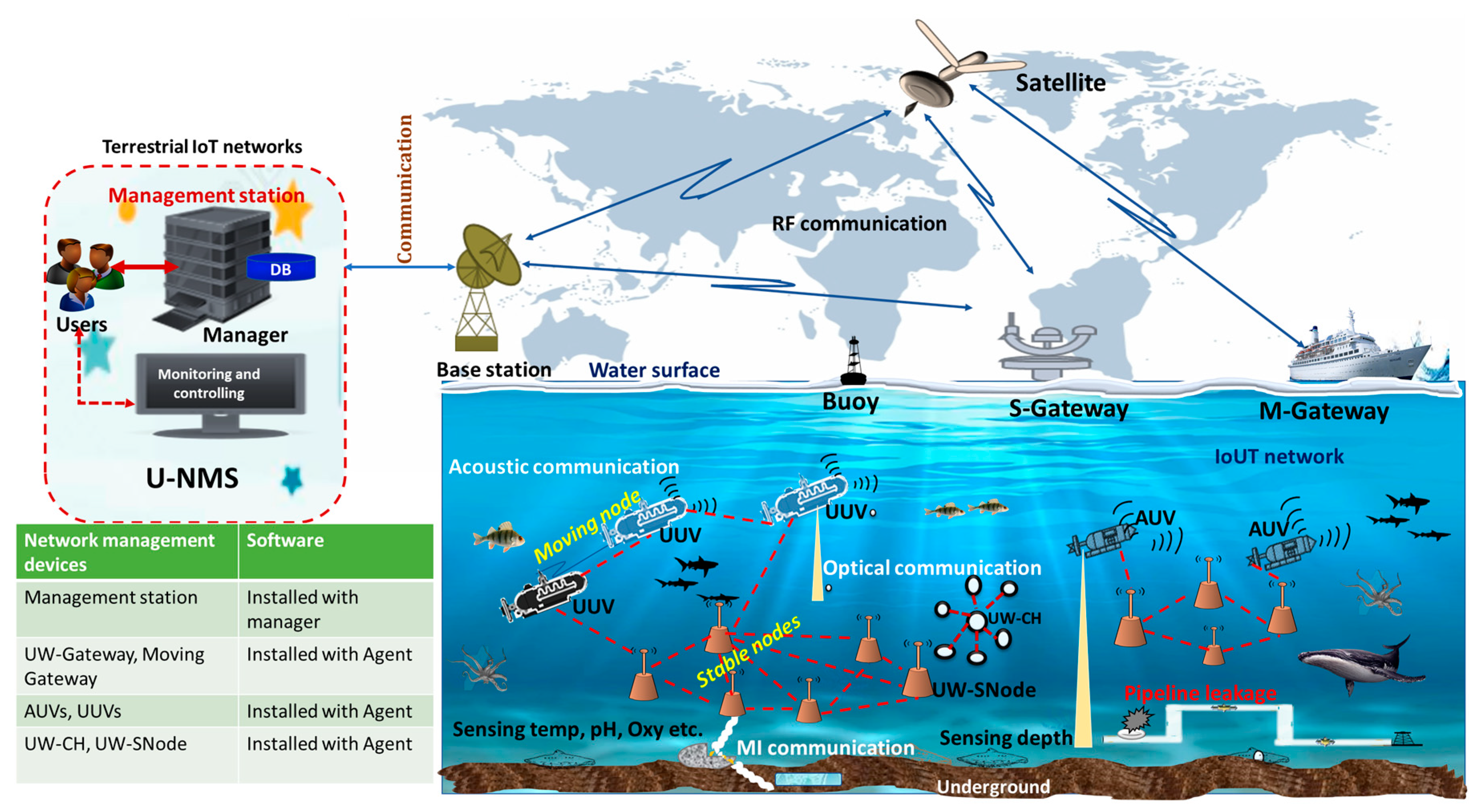
- AUVs/UUVs: In U-NMS, the AUV or UUV acts as the “mobile nodes” in the underwater communication system, which provides the degree of spatial reuse mechanism for localization tasks in U-NMS. The locations of AUVs/UUVs can be estimated through direct interaction with the S-GW in the water body. The acoustic medium can be used for collecting and transferring data in U-NMS [84,85,86].
- UW-CH: In U-NMS, the UW-CH is used for collecting the network management information from UW-SNode and transferring those data to AUVs or UUVs via acoustic communication.
- UW-SNode: In U-NMS, the UW-SNode is used for transferring the critical message of the UW-SNode itself to UW-CH or UUVs.
2.2. Literature Review on U-NMS
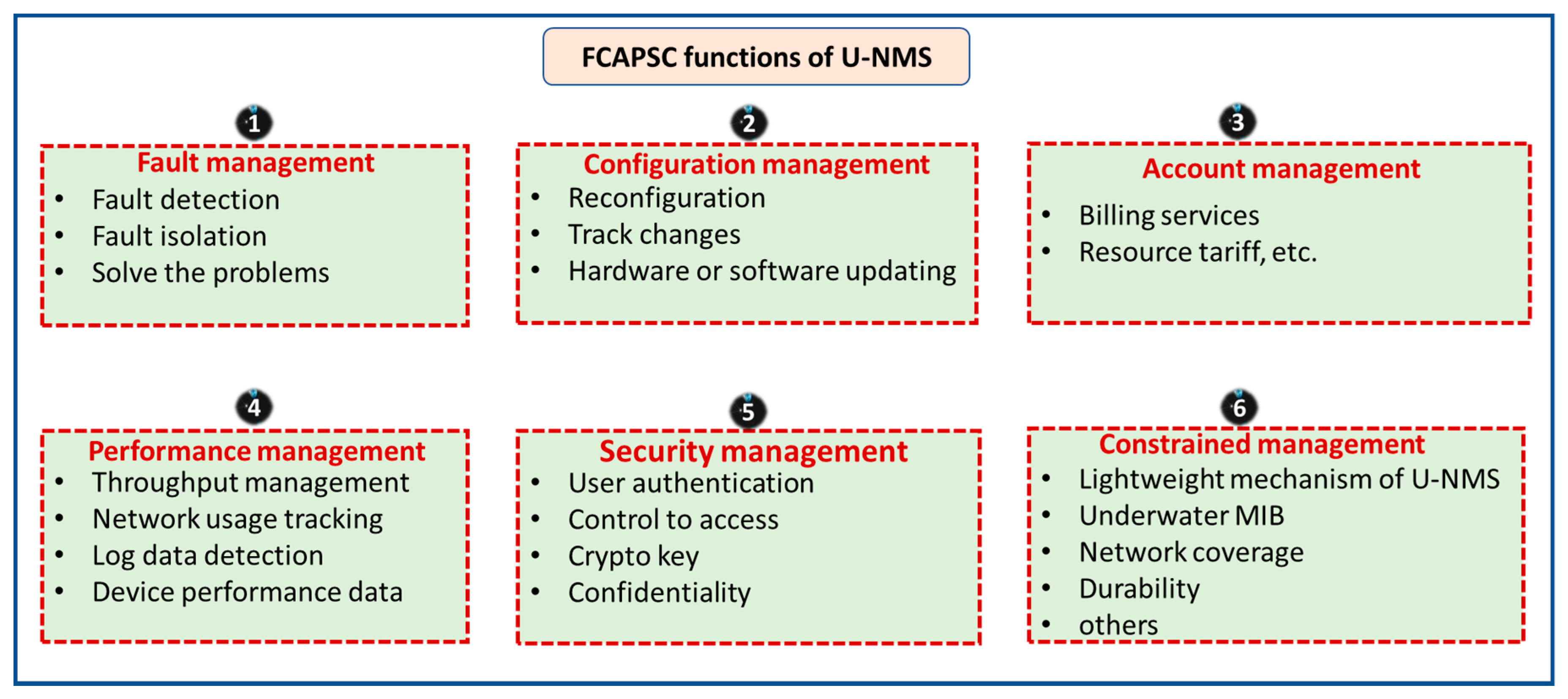
2.3. Functions Supporting U-NMS
- Fault Management (F) techniques for IoUT: In this level, network problems are identified and corrected. Possible future issues are identified, and actions are taken to stop them from recurring or occurring. Moreover, with the help of this, the network remains operational, and downtime will be minimized.
- Configuration Management (C) techniques for IoUT: In this level, network operation is observed and controlled. Programming and hardware changes, including new equipment addition and programs, the reform of existing systems, programs, and obsolete systems removal, are coordinated. In addition to this, equipment inventory and programs are retained and updated regularly.
- Accounting Management (A) techniques for IoUT: This level, also known as the allocation level, is dedicated to optimally as well as fairly distribute resources among several network subscribers. This makes use of the systems available in an effective way, reducing the operation cost. This level also ensures that the users are appropriately billed.
- Performance Management (P) techniques for IoUT: In this level, the management system collects network statistics and evaluates the system’s performance under different underwater condition.
- Security Management (S) techniques for IoUT: In this level, the network is secured against hackers, physical sabotage, unauthorized users, and electronic sabotage. The privacy of user information is preserved where it is warranted/necessary. Security systems also permit network administrators to resist what each authorized user can or cannot do to a system.
- Constrained Management (C) techniques for IoUT: This management is divided into 2 modules: (1) constrained network management and (2) constrained device management. In constrained management techniques, several steps are used to monitor and collect information from a constrained environment, such as battery power, memory level, connection status, etc., as summarized below.
- Lightweight mechanism: This module required a lightweight mechanism of system integration. Especially, the sustainability of message transmission should be lightweight and reduce message transmissions.
- The u-MIB integration: This module acts as a management database, such as lightweight enterprise MIB.
- Network coverage: This module integrated several modules of the function based on underwater network coverage specifications.
- System durability: This module can capture system durability and network possibilities, less error handling, and long-period system disabilities.
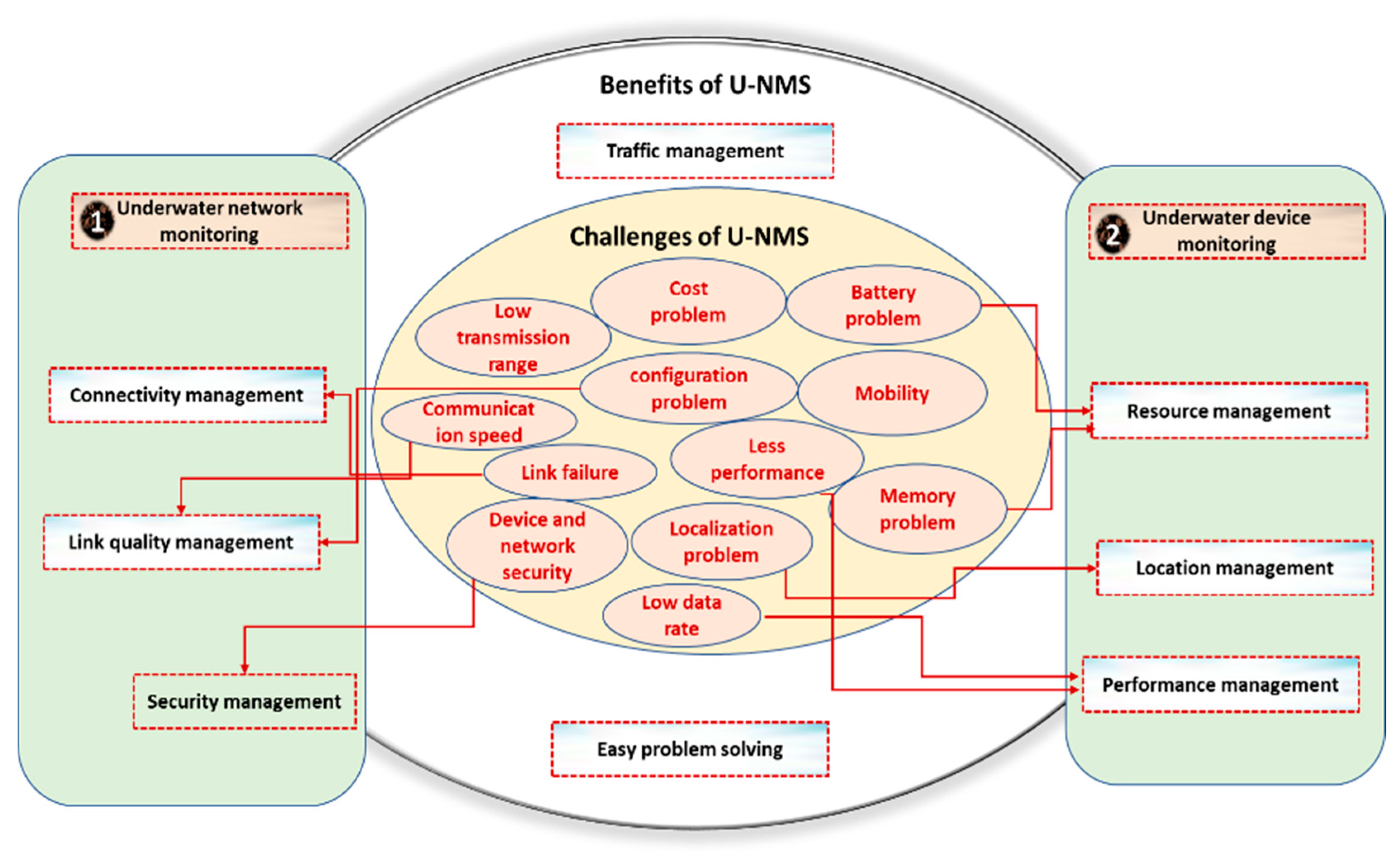
2.4. Challenges and Benefits of U-NMS
- Low data rates: Using low frequencies in underwater communication is the major cause of the low data rate. In addition, there are several problems inherent to medium like reflections, energy dispersion, refraction, etc., that significantly degrade the communication among devices [92].
- Localization in UWASN: Since radio frequency waves are highly attenuated, localization in underwater is highly challenging. Because of this, employing technology in devices such as GPS is not viable [93].
- Topology control: It is used to improve the technologies in underwater communication such as localization, time synchronization, mobility management, data reduction, energy-efficient network operation, and routing. Therefore, the topology control mechanism faces a massive challenge in underwater communication [94].
- Routing problem: The underwater communication generally relays on the acoustic and optical medium. This consumes a high battery for long-range acoustic communication and short-range optical communication. Therefore, for energy saving, it becomes a huge challenge to build energy-efficient routing protocols for underwater communication [95].
- Data collection: The data-gathering methods in UWSNs are considerably different than those in WSNs, due to high battery energy consumption, high propagation delay, and so on. Many of the proposed schemes still face difficulties in reliable data collection [96].
- Learning mechanisms: Deep learning or machine learning mechanisms require a massive amount of data support. With the wireless communication technology, along with a huge amount of data, there is an inherent benefit of applying a deep learning mechanism. However, the broad application of deep learning mechanisms in wireless sensor networks is still not fully developed, particularly in underwater acoustic sensor networks [97]. The convolutional neural network (CNN) is the widely used deep learning technology for image recognition and signal processing in wireless communication technology. However, the various factors of underwater communication, such as low contrast, turbidity, and complex light propagation, cause difficulty in obtaining the color of underwater objects [98,99].
- Transmission range: Only less distance can be covered by nodes in UWASN while considering the battery power planning and network coverage. Moreover, signals are generally transmitted in fewer frequencies underwater, so that there is less chance of being absorbed by water. This allows higher transmission ranges. However, this causes the chance for higher collision and interference [100].
- Data delivery rate: The successful delivery ratio of packets is affected considerably due to various factors such as traffic. The link reliability is typically unstable and low [100].
- Attenuation: The main reason for why attenuation is incited by absorption is the acoustic energy into heat energy conversion, which rises with distance, as well as frequency. Additionally, it is caused by reverberation and scattering (on the bottom and surface of the rough ocean), dispersion, and refraction (due to the reflection point of dispersion by surface wind). Attenuation is also determined by the depth of water depth [101].
- Depth of deployment: Underwater deployment is sparser compared with the earth bounded sensor networks (here, the lethargic deployment of sensors is done) due to the expenditure complexity [102].
- Antenna size: Due to the small size of the antenna deployed, network coverage issues persist.
- Data transmission delay: The propagation speed of underwater sensor networks is typically slow when compared to terrestrial networks. In the case of IoUT, bounded end-to-end delay ensuring can be a serious issue [103].
- Mobility: Underwater sensors can move due to water currents, and this leads to dynamic network topology changes, which is yet another challenging issue with IoUT [103].
- Cost: Compared with sensors underwater, terrestrial nodes are cheaper. This is due to the underwater transceiver’s complexity and the protection of hardware in an extreme underwater environment. Moreover, sensors are highly expensive, as the suppliers give low scale economies [103].
- Limitation in performance: In the underwater network management system, there is a limitation in performance, related to the measurement such as bandwidth, throughput, latency, error rate, etc. [50]
- Battery problem in IoUT devices: In the underwater network management system, load balancing is an essential part of smart sensing devices, since there is only limited power backup in underwater sensor nodes, and, a higher power has to be needed in the case of higher distance data transferring and complicated signal processing at the receiver. Therefore, high recharging cost is one of the major issues underwater [50,70].
- Underwater network monitoring and controlling, utilized for managing and controlling the underwater network-based functions, such as link quality, connectivity, network security, etc., in U-NMS.
- Underwater device monitoring and controlling utilized for controlling the underwater device-based functions, such as device name, ID, etc., in U-NMS.
- Function monitoring: utilized for monitoring all FCAPSC functions of U-NMS.
- Easy problem solving utilized for finding and solving the problems of networks and devices in U-NMS.
- Location management: utilized for finding the location of each device in U-NMS.
- Resource management: utilized for managing resources such as power level, memory space, etc., in U-NMS.
- Connectivity management: utilized for controlling the connection and communication between the devices underwater.
- Others: others required for extending other functionalities such as traffic management, security management, performance management, etc., in U-NMS.
2.5. Comparison Between NMS and U-NMS
3. Proposed U-NMS System
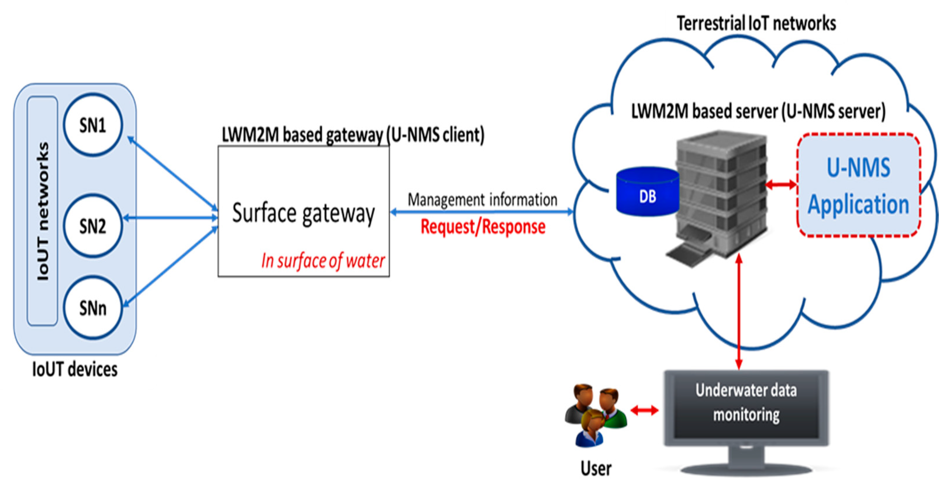
3.1. Conceptual Architecture of the Proposed System
3.2. Designing Mechanism of the Surface Gateway in U-NMS
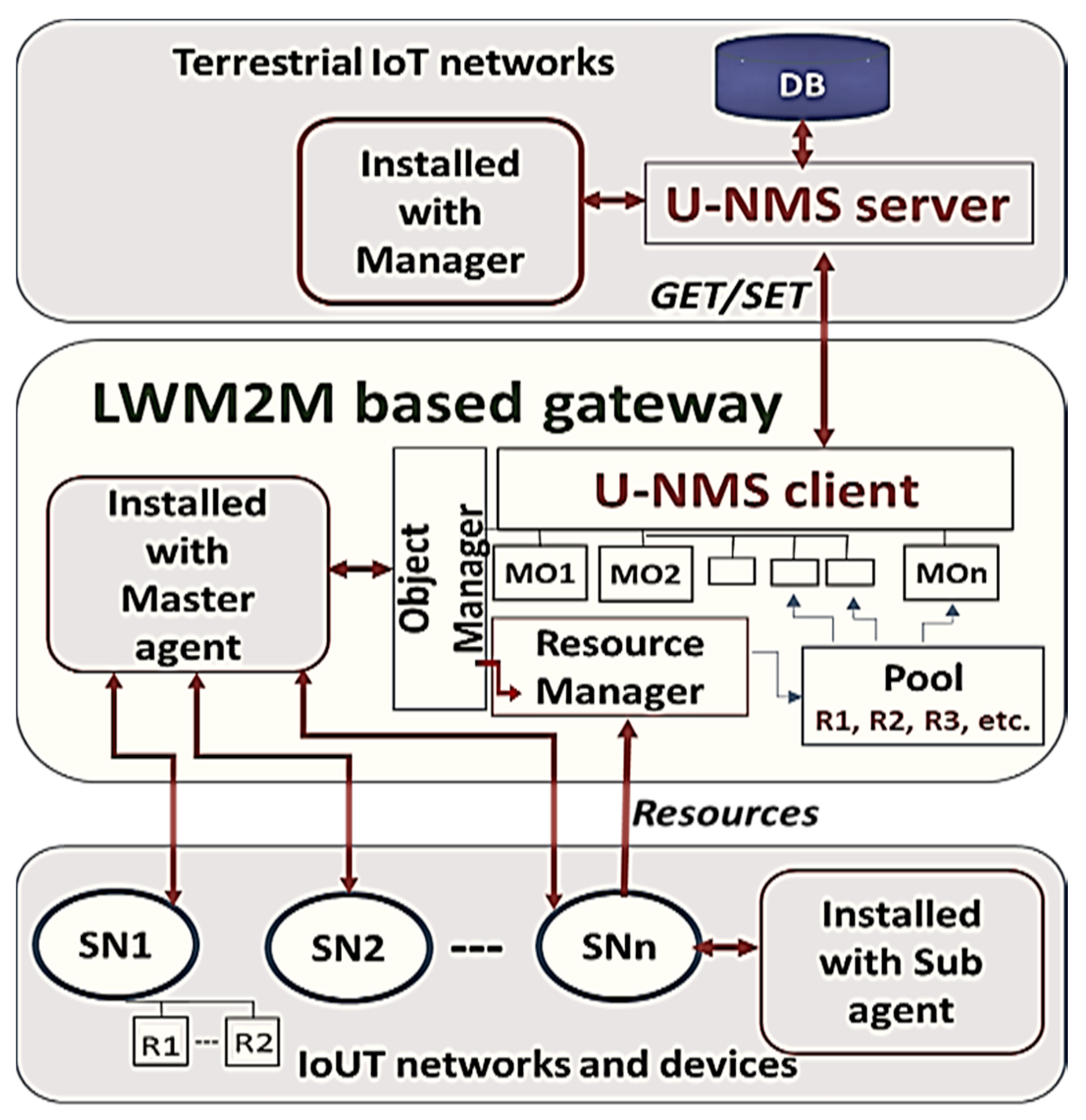
3.3. Prototype Design and Managed Objects Defining
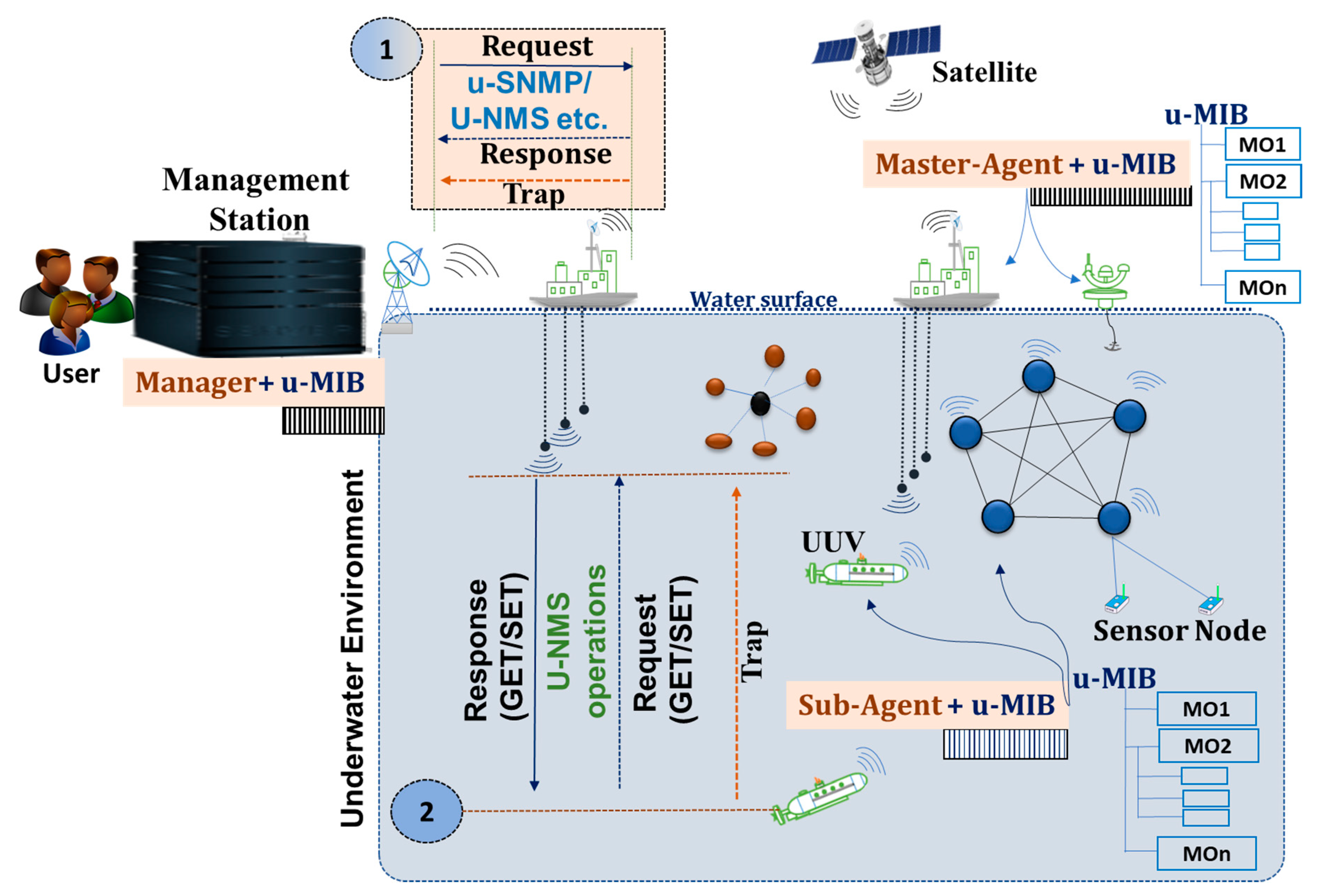
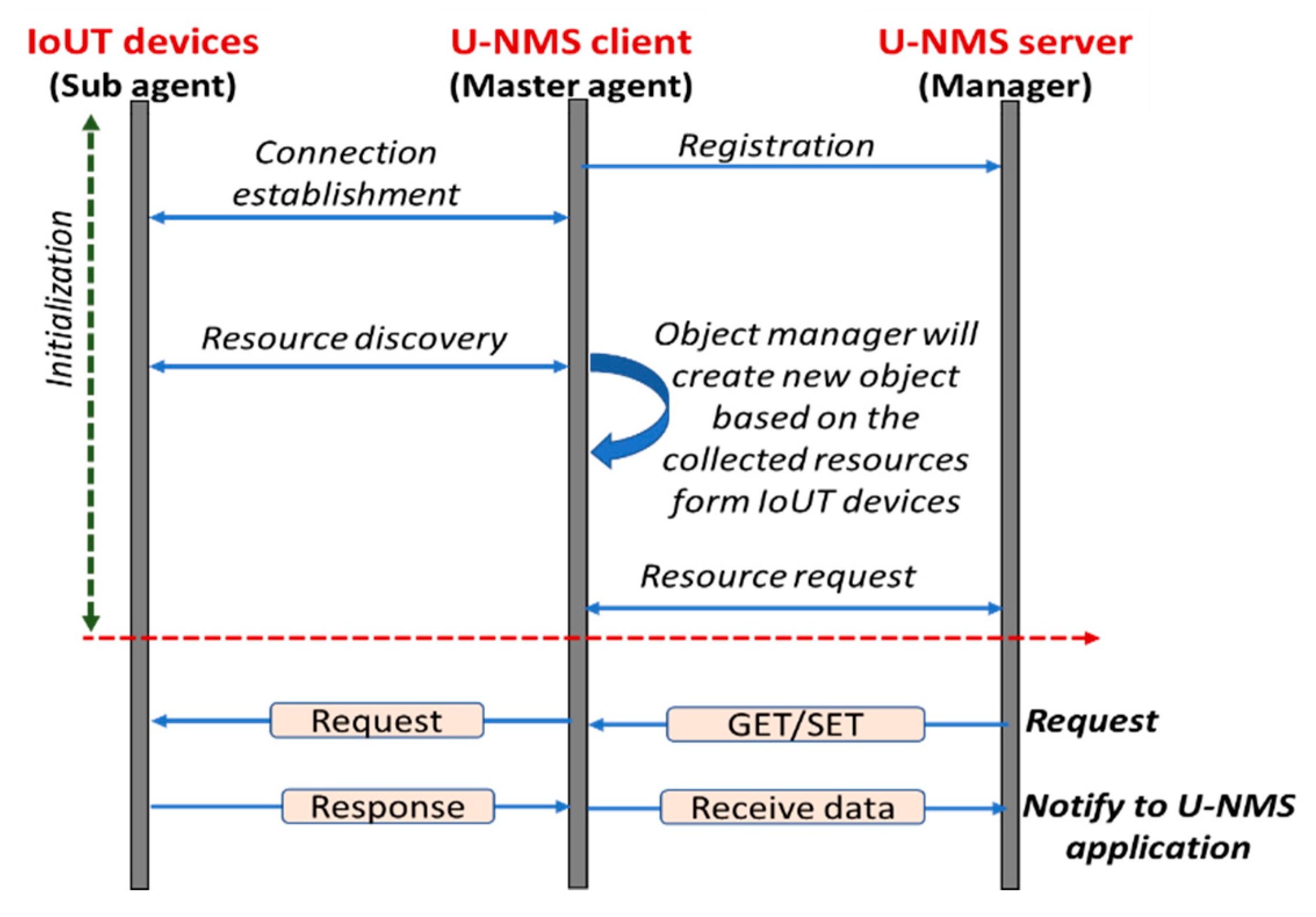
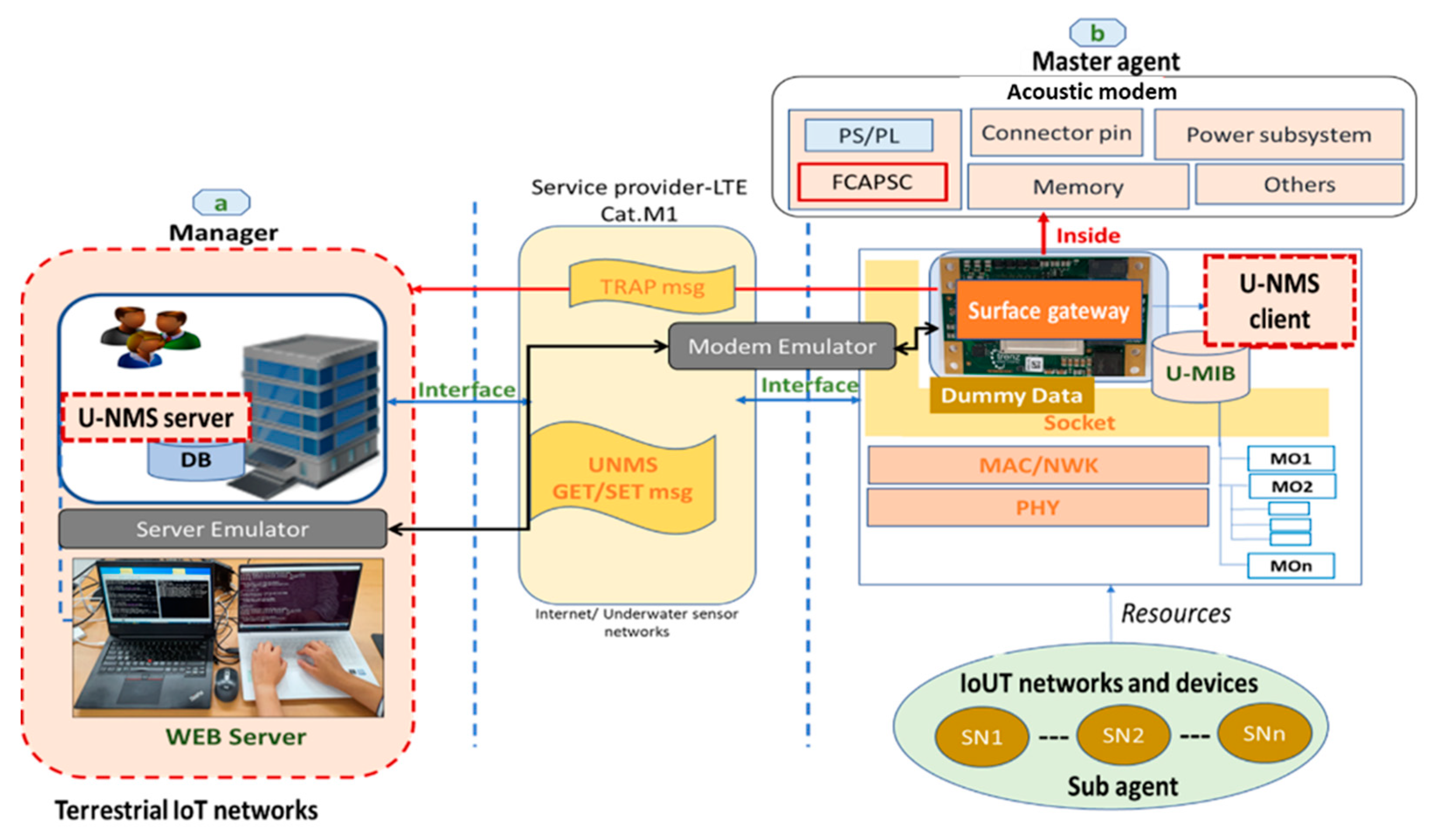
- U-NMS server: It consists of the manager program, which is used to manage the underwater networks and devices. For example, the operations such as GET/SET are used to get the information from U-NMS client in U-NMS.
- U-NMS client: It consists of a master agent program, which is used to send notification messages when some critical event occurs, and process the response message based on the request from the U-NMS server.
- Service Provider: In the proposed design, the LTE cat. M1 is the service provider that acts as the interface between user and surface-gateway to connect IoUT devices.
- Surface gateway: In our approach, the surface gateway acts as the U-NMS client.
- Device profile: It is the acoustic modem connected with acoustic transducer.
- MOs: The U-NMS client consists of a collection of managed objects (MOs). The managed objects can be accessed using the object identifier (OID).
- Underwater devices: The underwater devices are installed with the master agent, which can send the current resource information to U-NMS client.
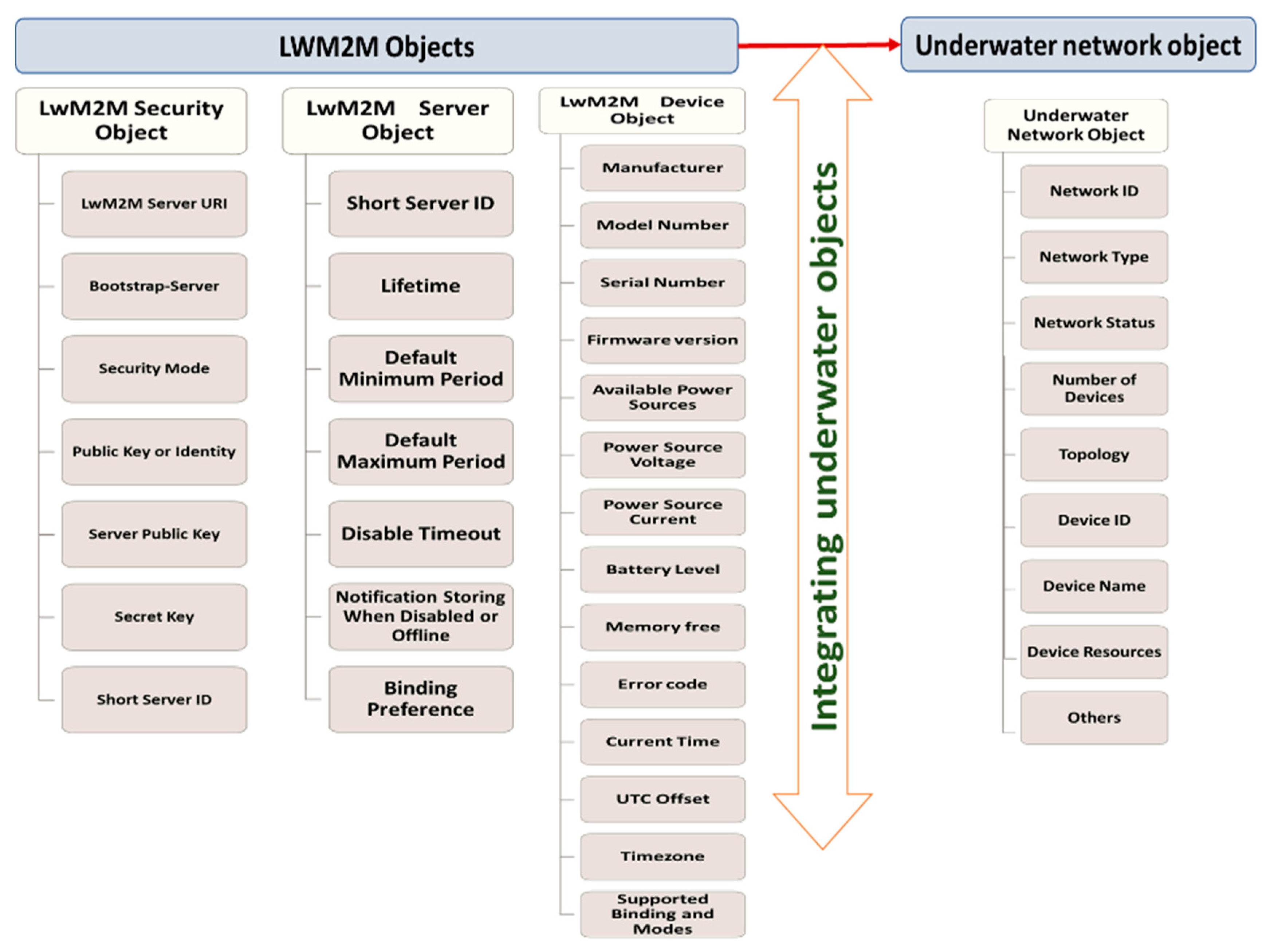
- Network ID: Unique identity of underwater networks.
- Network status: Quality of underwater networks (0 indicates a weak connection, 1 indicates a normal connection, 2 indicates strong connection).
- Number of devices: Indicates the number of devices connected to underwater networks.
- Device ID: Unique identity of underwater devices.
- Device Name: Indicates the name of the device, such as sensors, gateway, UUVs, etc.
- Devices resource: Indicates the availability of the resources, such as battery, memory, temperature status, etc., of underwater devices.
3.4. Testbed Description
3.4.1. Hardware Description
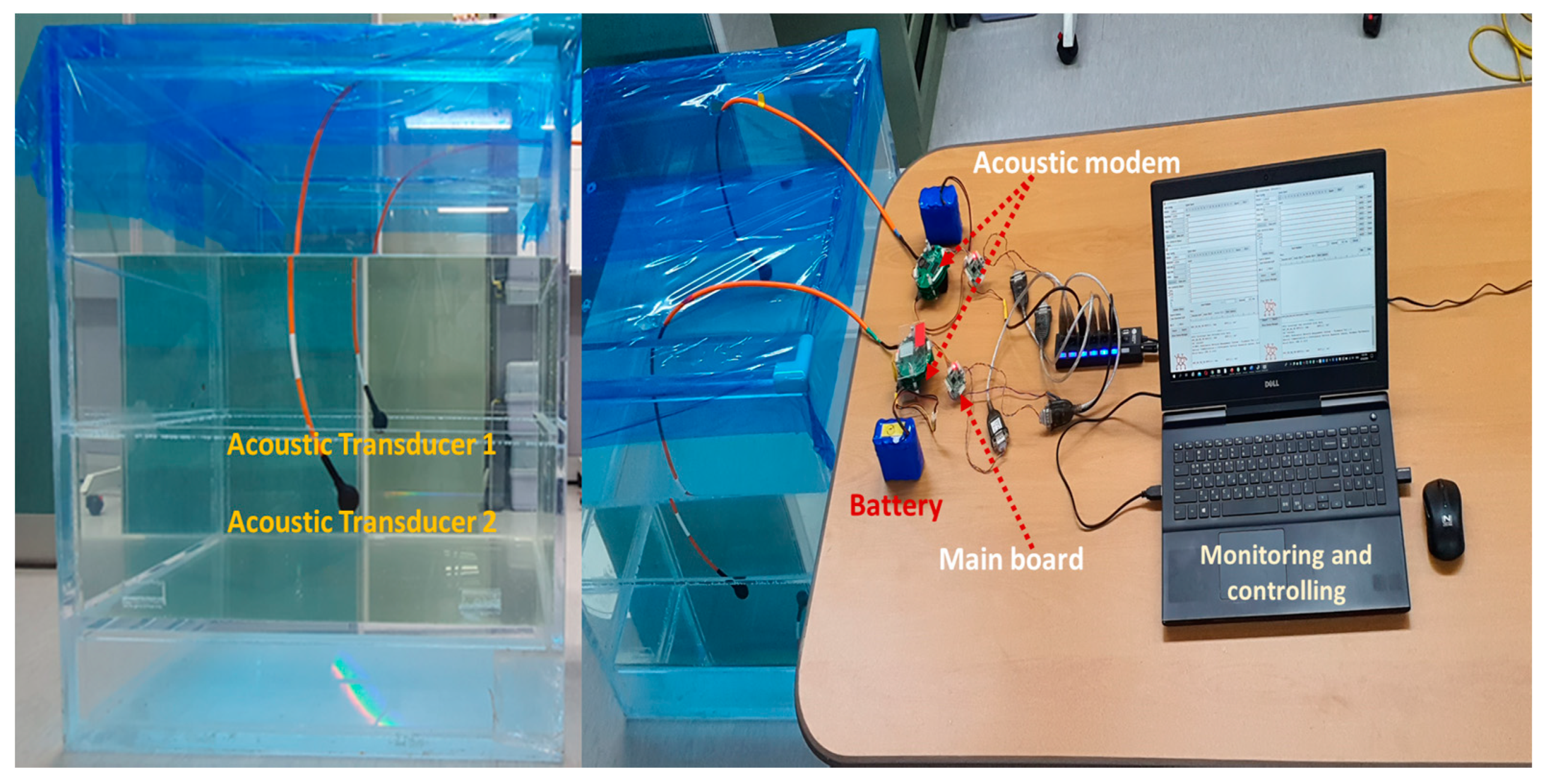
- Acoustic modem: The acoustic modem is designed with low power operation, which includes the MCU Cortex M3 processor, the operating frequency of 70 kHz, the maximum data rate of 200 bps, the maximum operational range of 50 m, and the dimension of radius 70 mm and height 40 mm. The serial peripheral interface (SPI) is used for the connection between the acoustic modem and the mainboard.
- The mainboard for U-NMS: STM32F103CB is utilized as the mainboard for U-NMS, which comprises of MCU Cortex M3 processor, installed with U-NMS module over the firmware, width, and height of 30 mm respectively and power consumption of 3.3 V and 5 V. The universal asynchronous receiver/transmitter (UART) interface is used for the communication between the mainboard and PC.
- Acoustic Transducer: The acoustic transducer supports the frequency range of 70 kHZ, with the input power of 190 watts, an operating depth of 1500 m, and uses the cable type of polyurethane 6 mm low noise coaxial.
- Water tank: The water tank is filled with water to create the underwater in lab environment, and the size is 75 cm × 75 cm × 100 cm—width, depth, and height, respectively.
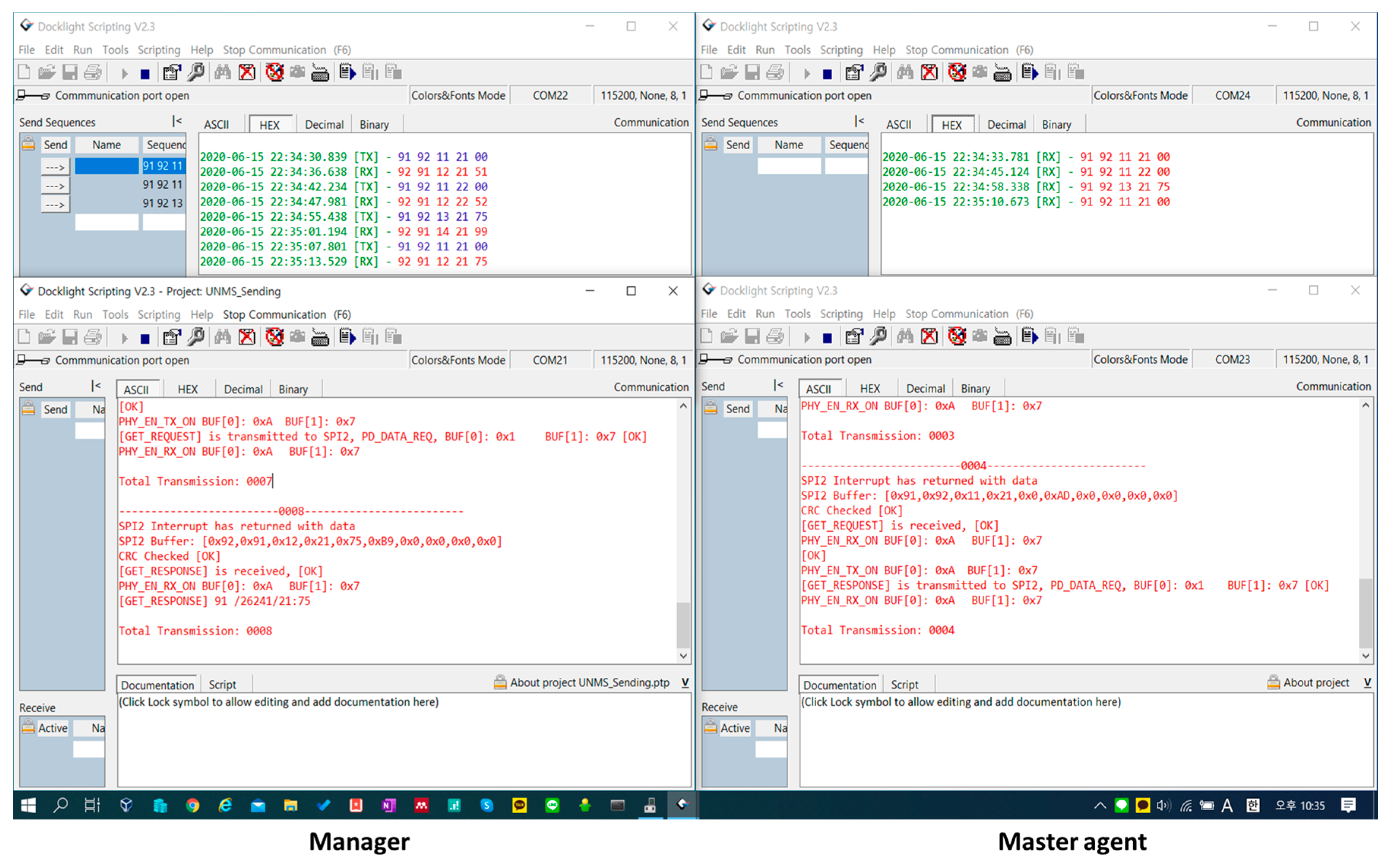
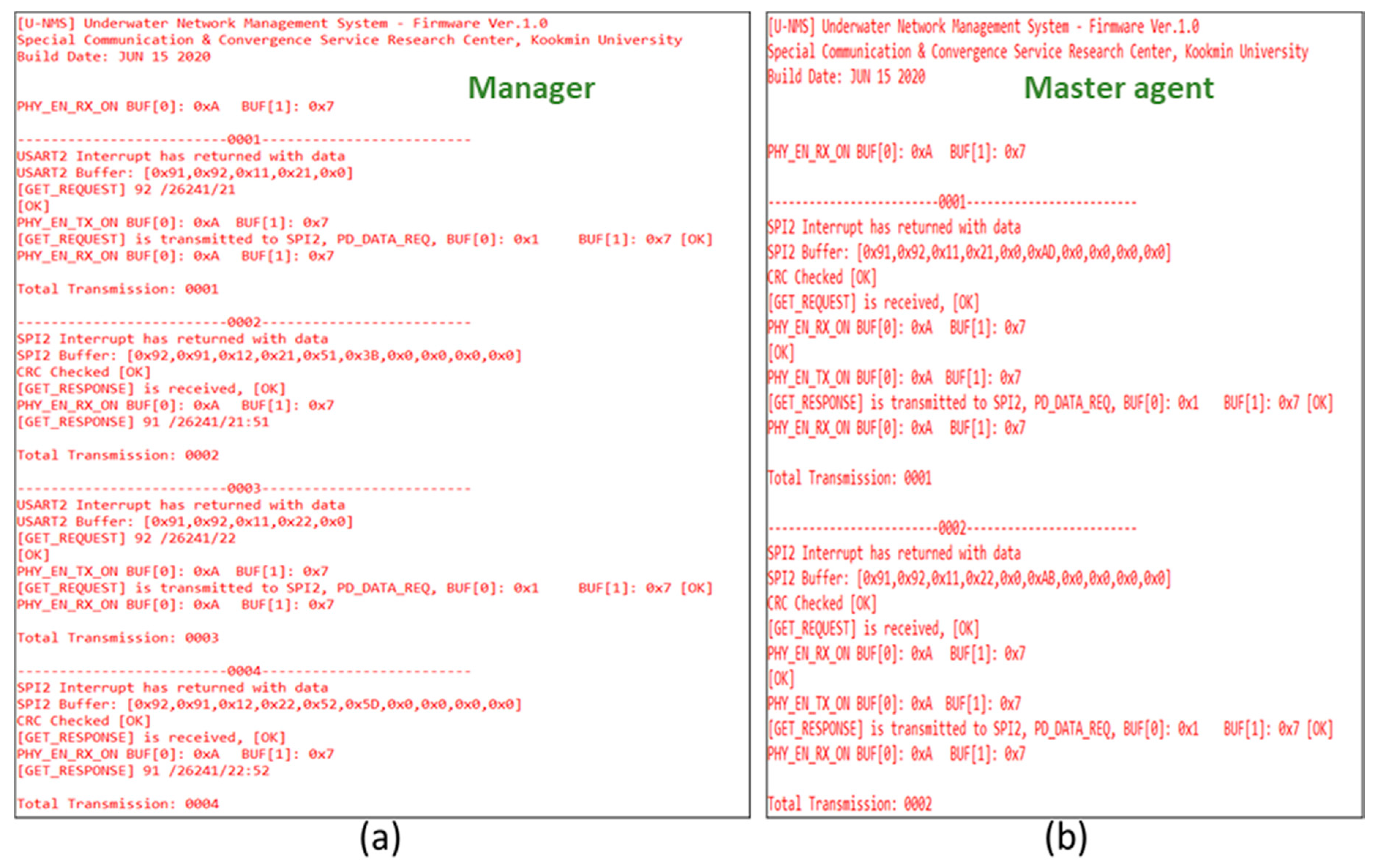
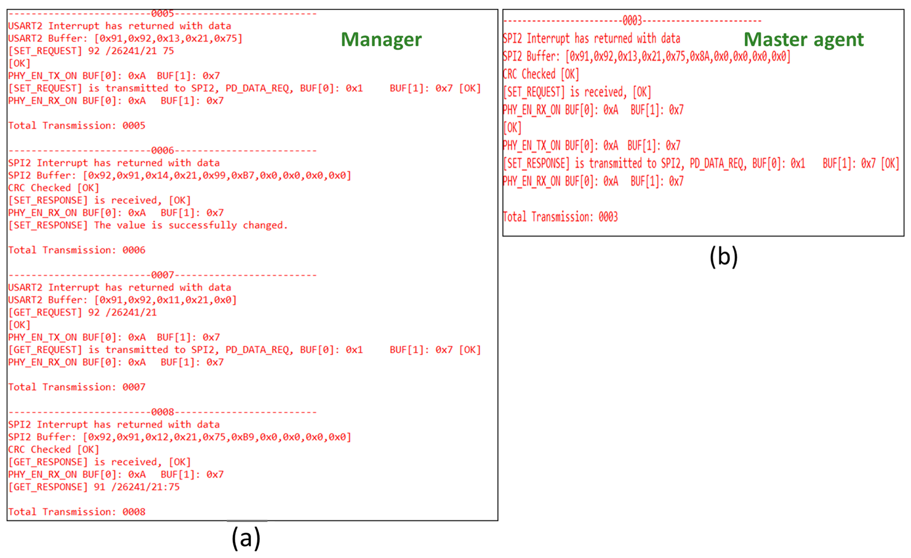
- Manger/master agent: The PC is utilized for monitoring and controlling the operations of the U-NMS system. In this U-NMS system, the modem is connected to the serial port to GET-REQUEST, GET-RESPONSE, SET REQUEST, and, SET RESPONSE, from the manger and master agent.
3.4.2. Protocol Stack of U-NMS
- Application layer for U-NMS: The U-NMS application is installed inside the application layer of U-NMS. The U-NMS application module is employed here for the management of functions in U-NMS. The methods, such as GET REQUEST, GET RESPONSE, SET REQUEST, and SET RESPONSE, are used for transferring the U-NMS information.
- Data Link layer of U-NMS: The mainboard of U-NMS is connected to the U-NMS data link layer. The U-NMS module is installed in this layer for transferring the information base on the request. The functions such as data processing, error detection, and handling, data framing, schedule management, etc. are used in the data link layer of U-NMS.
- Physical layer of U-NMS: The functions, such as signal generation, binary transmission, acoustic medium for transmission, etc., are performed in the physical layer of U-NMS.
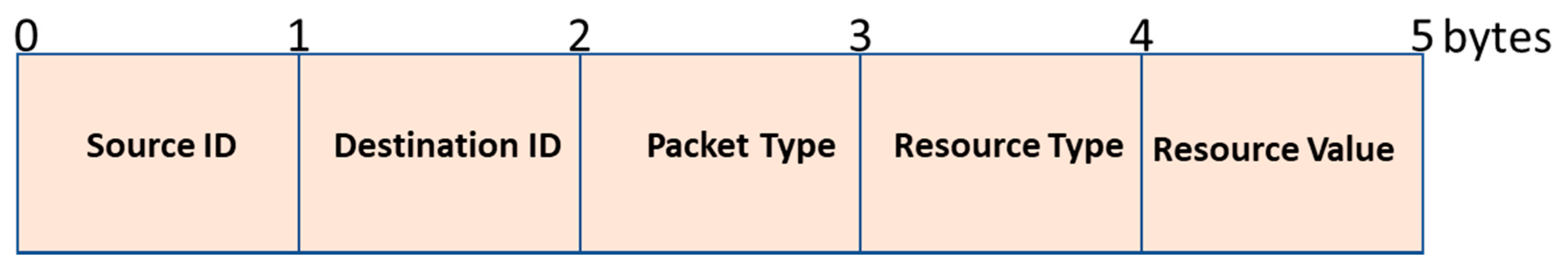
3.5. Laboratory Experiment Results
- Source ID and Destination ID are used to identify the source and destination in U-NMS.
- Packet Types are the methods used in the U-NMS, such as GET_REQUEST: 0 × 11, GET_RESPONSE: 0 × 12, SET_REQUEST: 0 × 13, and SET_RESPONSE: 0 × 14.
- Resource Type is the various MO values used in the U-NMS, such as Network ID, Network status, Device ID, Device name, Device Resources, etc.
- Resource Value is the MO values used for GET_REQUEST/GET_RESPONSE and SET_REQUEST/SET_RESPONSE in U-NMS.
4. Conclusions and Future Direction
Author Contributions
Funding
Conflicts of Interest
References
- Qiu, T.; Chen, N.; Li, K.; Qiao, D.; Fu, Z. Heterogeneous ad hoc networks: Architectures, advances and challenges. Ad Hoc Netw. 2017, 55, 143–152. [Google Scholar] [CrossRef]
- Chen, S.; Xu, H.; Liu, D.; Hu, B.; Wang, H. A vision of IoT: Applications, challenges, and opportunities with China perspective. IEEE Internet Things J. 2014, 1, 349–359. [Google Scholar] [CrossRef]
- Zanella, A.; Bui, N.; Castellani, A.; Vangelista, L.; Zorzi, M. Internet of things for smart cities. IEEE Internet Things J. 2014, 1, 22–32. [Google Scholar] [CrossRef]
- Chettri, L.; Bera, R. A Comprehensive survey on Internet of Things (IoT) toward 5G wireless systems. IEEE Internet Things J. 2020, 7, 16–32. [Google Scholar] [CrossRef]
- ISO/IEC 10040:1998. Recommendation X.701–Information Technology–Open Systems Interconnection–Systems Management Overview; ITU-T: Geneva, Switzerland, 1997. [Google Scholar]
- Jia, L.; Zhu, W.; Zhai, C.; Du, Y. Research on an integrated network management system. In Proceedings of the Eighth ACIS International Conference on Software Engineering, Artificial Intelligence, Networking, and Parallel/Distributed Computing (SNPD 2007), Qingdao, China, 30 July 30–1 August 1 2007; pp. 311–316. [Google Scholar]
- Dragomir, D.; Voinescu, A.; Draghici, A.; Tapus, N. WSN management in a multi-user secure context. In Proceedings of the 11th RoEduNet International Conference, Sinaia, Romania, 17–19 January 2013; pp. 1–4. [Google Scholar] [CrossRef]
- Pras, A.; Schönwälder, J.; Burgess, M.; Festor, O.; Martinez Perez, G.; Stadler, R.; Stiller, B. Key research challenges in network management. IEEE Commun. Mag. 2007, 45, 104–110. [Google Scholar] [CrossRef][Green Version]
- Goers, W.; Brenner, M. Implementing a management system architecture framework. Bell Labs Tech. J. 2002, 5, 31–43. [Google Scholar] [CrossRef]
- Bush, S.F.; Kalyanaraman, S. Management of active and programable networks. J. Netw. Syst. Manag. 2006, 14, 1–5. [Google Scholar] [CrossRef]
- Rao, U.H. Challenges of Implementing Network Management Solution. Int. J. Distrib. Parallel Syst. 2011, 2, 67–76. [Google Scholar] [CrossRef]
- Ma, Y.-W.; Chen, J.-L.; Huang, Y.-M.; Lee, M.-Y. An efficient management system for wireless sensor networks. Sensors 2010, 10, 11400–11413. [Google Scholar] [CrossRef]
- Kurose, J.F.; Ross, K.W. Computer Networking: A Top-Down Approach Featuring the Internet, 6th ed.; Pearson: London, UK, 2010. [Google Scholar]
- Silva, J.C.; Rodrigues, J.J.P.C.; Al-Muhtadi, J.; Rabêlo, R.A.L.; Furtado, V. Management platforms and protocols for internet of things: A survey. Sensors 2019, 19, 676. [Google Scholar] [CrossRef]
- Case, J.; Fedor, M.; Schoffstall, M.; Davin, J. RFC 1157—Simple Network Management Protocol (SNMP). Network Working Group. May 1990. Available online: https://tools.ietf.org/html/rfc1157/ (accessed on 1 May 2020).
- Specialski, E.S. Management of Computer Networks and Telecommunications. Master’s Thesis, University of Santa Catarina, Florianópolis, SC, USA, 2002. [Google Scholar]
- SNMP Research. Simple Network Management Protocol. SNMP Research International. Available online: http://www.snmp.com/protocol/ (accessed on 1 May 2020).
- ASN.1 PROJECT. Introduction to ASN.1. ITU-T. Available online: http://www.itu.int/en/ITU-T/asn1/Pages/introduction.aspx (accessed on 1 May 2020).
- Enns, R.; Bjorklund, M.; Schoenwaelder, J.; Bierman, A. RFC 6241—Network Configuration Protocol (NETCONF). Internet Engineering Task Force (IETF). June 2011. Available online: https://tools.ietf.org/html/rfc6241 (accessed on 1 May 2020).
- Bjorklund, M. RFC 6020—YANG—A Data Modeling Language for NETCONF. Internet Engineering Task Force (IETF). October 2010. Available online: https://tools.ietf.org/html/rfc6020 (accessed on 1 May 2020).
- Chappell, C. White Paper Creating the Programmable Network: The Business Case for NETCONF/YANG in Network Devices; Heavy Reading: New York, NY, USA, 2013. [Google Scholar]
- Warrier, U.; Corporation, U.; Besaw, L. Hewlett-Packard RFC 1189—The Common Management Information Services and Protocols for the Internet. Network Working Group. October 1990. Available online: https://tools.ietf.org/html/rfc1189 (accessed on 1 May 2020).
- Ying, D.; Feng, Q.; Luoming, M. Implementation of a CMIP-based management interface for optical access network. In Proceedings of the Fifth Asia-Pacific Conference on Communications and Fourth Optoelectronics and Communications Conference on Communications, Beijing, China, 18–22 October 1999; Volume 1, pp. 87–90. [Google Scholar]
- Sehgal, A.; Perelman, V.; Kuryla, S.; Schönwälder, J. Management of resource constrained devices in the internet of things. IEEE Commun. Mag. 2012, 50, 144–149. [Google Scholar] [CrossRef]
- Kushalnagar, N.; Montenegro, G.; Schumacher, C. RFC 4919—6LoWPAN: Overview, Assumptions, Problem Statement and Goals; Network Working Group: Gatineau, QC, Canada, August 2007. [Google Scholar]
- Mukhtar, H.; Kang-myo, K.; Chaudhry, S.A.; Akbar, A.H.; Ki-hyung, K.; Yoo, S. LNMP—Management Architecture for IPv6 based low-power Wireless Personal Area Networks (6LoWPAN). In Proceedings of the Network Operations and Management Symposium, Salvador Da Bahia, Brazil, 7–11 April 2008; pp. 417–424. [Google Scholar]
- Bierman, A.; Bjorklund, M.; Watsen, K. RFC 8040—RESTCONF Protocol. January 2017. Available online: https://tools.ietf.org/html/rfc8040 (accessed on 1 May 2020).
- Prieto, A.G.; Leung, A.; Rockwell, K. Automating the testing of RESTCONF agents. In Proceedings of the 2015 IFIP/IEEE International Symposium on Integrated Network Management (IM), Ottawa, ON, Canada, 11–15 May 2015; pp. 984–989. [Google Scholar]
- Pfa, B.; Davie, B. RFC 7047—The Open vSwitch Database Management Protocol. Internet Engineering Task Force (IETF). December 2013. Available online: https://tools.ietf.org/html/rfc7047 (accessed on 1 May 2020).
- Davie, B.; Koponen, T.; Pettit, J.; Pfa, B.; Casado, M.; Gude, N.; Petty, T. Public review for a databaseapproach to SDN control plane design. ACM SIGCOMM Comput. Commun. Rev. 2017, 47, 15–26. [Google Scholar] [CrossRef]
- Sharma, S.; Staessens, D.; Colle, D.; Palma, D.; Goncalves, J.; Figueiredo, R.; Morris, D.; Pickavet, M.; Demeester, P.; Sharma, S.; et al. Implementing quality of service for the software defined networking enabled future internet. In Proceedings of the 2014 Third European Workshop on Software Defined Networks, London, UK, 1–3 September 2014; pp. 49–54. [Google Scholar]
- Klas, G.; Rodermund, F.; Shelby, Z.; Akhouri, S.; Höller, J. Lightweight M2M: Enabling device management and applications for the internet of things. In Ericsson and Vodafone White Paper; Ericsson: Stockholm, Sweden, 2014. [Google Scholar]
- Ocak, M.C. Implementation of an Internet of Things Device Management Interface. Master’s Thesis, School of Electrical Engineering, Alto University, Greater Helsinki, Finland, November 2014. [Google Scholar]
- Rao, S.; Chendanda, D.; Deshpande, C.; Lakkundi, V. Implementing LWM2M in constrained IoT devices. In Proceedings of the IEEE ICWiSe 2015, Melaka, Malaysia, 24–26 August 2015. [Google Scholar]
- Open Mobile Alliance (OMA). OMA DM Device Description Framework; Version 1.3; OMA: San Diego, CA, USA, October 2012. [Google Scholar]
- Open Mobile Alliance (OMA). OMA Device Management Tree and Description; Version 1.3; OMA: San Diego, CA, USA, October 2012. [Google Scholar]
- Open Mobile Alliance (OMA). OMA Device Management Protocol; Version 1.3; OMA: San Diego, CA, USA, May 2016. [Google Scholar]
- Lamaazi, H.; Benamar, N.; Jara, A.; Ladid, L.; El Ouadghiri, D. Internet of thing and networks management: Lnmp, snmp, coman protocols. In Proceedings of the First International Workshop on Wireless Networks and Mobile COMmunications (WINCOM 2013), Fes, Morocco, 25 December 2013; pp. 1–5. [Google Scholar]
- Sheng, Z.; Wang, H.; Yin, C.; Hu, X.; Yang, S.; Leung, V.C. Lightweight management of resource-constrained sensor devices in internet of things. IEEE Internet Things J. 2015, 2, 402–411. [Google Scholar] [CrossRef]
- Castro, M.; Jara, A.J.; Skarmeta, A.F. Enabling end-to-end CoAP based communications for the web of things. J. Netw. Comput. Appl. 2016, 59, 230–236. [Google Scholar] [CrossRef]
- Dai, G. Design and implementation on SOAP-based things management protocol for internet of things. In Proceedings of the 10th World Congress Intelligent Control and Automation (WCICA), Beijing, China, 6–8 July 2012; pp. 4305–4308. [Google Scholar]
- Oetiker, T. MRTG–The Multi Router Traffic Grapher. In LISA 1998: Proceedings of the 12th USENIX Conference on System Administration; USENIX Association: Berkeley, CA, USA, 1998; pp. 141–148. [Google Scholar]
- Apel, U. Intelligent network management systems. In Proceedings of the X International Symposium on Subscriber Loops and Services, Vancouver, BC, Canada, 27 September–1 October 1993; pp. 257–264. [Google Scholar] [CrossRef]
- Otani, T. An integrated management system architecture for utility telecommunication networks. Integrated Network Management VI. Distributed Management for the Networked Millennium. In Proceedings of the Sixth IFIP/IEEE International Symposium on Integrated Network Management. (Cat. No.99EX302), Boston, MA, USA, 24–28 May 1999; pp. 933–934. [Google Scholar]
- Kim, J.-Y.; Lim, S.-D.; Hong, J.W.; Kim, S.-B.; Lee, H.-Y. TMN-based integrated network management using Web and CORBA. Integrated Network Management VI. Distributed Management for the Networked Millennium. In Proceedings of the Sixth IFIP/IEEE International Symposium on Integrated Network Management. (Cat. No.99EX302), Boston, MA, USA, 24–28 May 1999; pp. 947–948. [Google Scholar]
- Zhang, T.; Xu, C.; Wu, M.; Zhen, Y.; Zhang, Q.; Wen, J. Implementation of Ad Hoc Network management system based on embedded ARM-Linux platform. In Proceedings of the 2010 International Conference on Networking and Digital Society, Wenzhou, China, 30–31 May 2010; pp. 167–170. [Google Scholar]
- Tsatsoulis, C.; Soh, L.-K. Intelligent agents in telecommunication networks. In Computational Intelligence in Telecommunications Networks; CRC Press: Boca Raton, FL, USA, 2000. [Google Scholar]
- Atzori, L.; Iera, A.; Morabito, G. The internet of things: A survey. Comput. Netw. 2010, 54, 2787–2805. [Google Scholar] [CrossRef]
- Singh, K.J.; Kapoor, D.S. Create your own internet of things: A survey of IoT platforms. IEEE Consum. Electron. Mag. 2017, 6, 57–68. [Google Scholar] [CrossRef]
- Urunov, K.; Shin, S.-Y.; Park, S.-H.; Lim, Y.K. Analysis of the network management system with constrained underwater devices. In Proceedings of the Symposium of the Korean Institute of Communications and Information Sciences, Seoul, Korea, 21–23 June 2017. [Google Scholar]
- Urunov, K.; Shin, S.-Y.; Namgung, J.-I.; Park, S.-H. Designing of use cases for the U-NMS. J. Inst. Electron. Eng. Korea 2018, 55, 47–59. [Google Scholar]
- Kao, C.-C.; Lin, Y.-S.; Wu, G.-D.; Huang, C.-J. A comprehensive study on the internet of underwater things: Applications, challenges, and channel models. Sensors 2017, 17, 1477. [Google Scholar] [CrossRef]
- Duraibabu, D.B.; Leen, G.; Toal, D.; Newe, T.; Lewis, E.; Dooly, G. Underwater depth and temperature sensing based on fiber optic technology for marine and fresh water applications. Sensors 2017, 17, 1228. [Google Scholar] [CrossRef] [PubMed]
- Mellin, T.A.; Ravik, O. Autonomous underwater system for pipeline leak detection and inspection. In Proceedings of the 6th International Symposium on Unmanned Untethered Submersible Technology, Durham, NH, USA, 12–14 June 1989; pp. 15–24. [Google Scholar]
- Prasad, A.N.; Mamun, K.; Islam, F.; Haqva, H. Smart water quality monitoring system. In Proceedings of the 2nd Asia-Pacific World Congress on Computer Science and Engineering (APWC on CSE), Nadi, Fiji, 2–4 December 2015. [Google Scholar] [CrossRef]
- Qin, Y.; Alam, A.U.; Pan, S.; Howlader, M.; Ghosh, R.; Hu, N.-X.; Jin, H.; Dong, S.; Chen, C.-H.; Deen, J. Integrated water quality monitoring system with pH, free chlorine, and temperature sensors. Sens. Actuators B Chem. 2018, 255 Pt 1, 781–790, ISSN 0925–4005. [Google Scholar] [CrossRef]
- Khan, A.; Jenkins, L. Undersea wireless sensor network for ocean pollution prevention. In Proceedings of the Communication Systems Software and Middleware and Workshops, 2008. COMSWARE 2008. 3rd International Conference on, Bangalore, India, 6–10 January 2008. [Google Scholar] [CrossRef]
- Delphin Raj, K.M.; Shin, S.-y.; Namgung, J.-I.; Park, S.-H. The RIL based approach for predicting the growth of pearl spot fish using-UWAC. J. Inst. Electron. Inf. Eng. 2018, 55, 32–40. [Google Scholar]
- Ainbridge, S.; Eggeling, D.; Page, G. Lessons from the field—two years of deploying operational wireless sensor networks on the great barrier reef. Sensors 2011, 11, 6842–6855. [Google Scholar] [CrossRef]
- Davis, A.; Chang, H. Underwater wireless sensor networks. In Proceedings of the OCEANS 2012 MTS/IEEE: Harnessing the Power of the Ocean, Virginia Beach, VA, USA, 14–19 October 2012. [Google Scholar] [CrossRef]
- Chuang, M.-C.; Hwang, J.N.; Ye, J.-H.; Yeh, W.-c.; Williams, K. Underwater fish tracking for moving cameras based on deformable multiple kernels. IEEE Trans. Syst. Man Cybern. Syst. 2016, 47, 1–11. [Google Scholar] [CrossRef]
- Udo, E.; Isong, E. Flood monitoring and detection system using wireless sensor network. Asian J. Comput. Inf. Syst. 2014, 1, 2321–5658. [Google Scholar]
- Kumar, P.; Kumar, P.; Priyadarshini, P. Underwater acoustic sensor network for early warning generation. In Proceedings of the 2012 Oceans, Hampton Roads, VA, USA, 14–19 October 2012; pp. 1–6. [Google Scholar] [CrossRef]
- Wang, Y.; Dong, J.; Xie, F. A design of simple underwater wireless communication system. In Proceedings of the 2010 International Conference on Internet Technology and Applications, Wuhan, China, 20–22 August 2010; pp. 1–4. [Google Scholar] [CrossRef]
- Rao, C.; Mukherjee, K.; Gupta, S.; Ray, A.; Phoha, S. Underwater mine detection using symbolic pattern analysis of sidescan sonar images. In Proceedings of the 2009 American Control Conference, St. Louis, MO, USA, 10–12 June 2009; pp. 5416–5421. [Google Scholar] [CrossRef]
- KM, D.R.; Yum, S.-H.; Ko, E.; Shin, S.-Y.; Namgung, J.-I.; Park, S.-H. Multi-Media and Multi-Band based adaptation layer techniques for underwater sensor networks. Appl. Sci. 2019, 9, 3187. [Google Scholar] [CrossRef]
- Sanap, M.; Chaudhari, S.; Vartak, C.; Chimurkar, P. HYDROBOT: An underwater surveillance swimming robot. In Proceedings of the 2018 International Conference on Communication information and Computing Technology (ICCICT), Mumbai, India, 2–3 February 2018; pp. 1–7. [Google Scholar] [CrossRef]
- Bernardina, G.R.D.; Cerveri, P.; Barros, R.M.L.; Marins, J.C.B.; Silvatti, A.P. Action sport cameras as an instrument to perform a 3D underwater motion analysis. PLoS ONE 2016, 11, e0160490. [Google Scholar] [CrossRef]
- Han, Y.; Zheng, C.; Sun, D. Accurate underwater localization using LBL positioning system. In Proceedings of the OCEANS 2015-MTS/IEEE Washington, Washigton, DC, USA, 19–22 October 2015; pp. 1–4. [Google Scholar] [CrossRef]
- Urunov, K.; Shin, S.-Y.; Namgung, J.-I.; Park, S.-H. High-Level architectural design of management system for the internet of underwater things. In Proceedings of the 2018 Tenth International Conference on Ubiquitous and Future Networks (ICUFN), Prague, Czech Republic, 3–6 July 2018; pp. 326–331. [Google Scholar]
- Akyildiz, I.; Pompili, D.; Melodia, T. Challenges for efficient communication in underwater acoustic sensor networks. ACM SIGBED Rev. 2004, 1. [Google Scholar] [CrossRef]
- Yang, H.; Alphones, A.; Xiong, Z.; Niyato, D.; Zhao, J.; Wu, K. Artificial Intelligence-Enabled Intelligent 6G Networks. arXiv 2019, arXiv:1912.05744. [Google Scholar]
- Kao, C.; Lin, Y.; Wu, G.; Huang, C. A study of applications, challenges, and channel models on the Internet of Underwater Things. In Proceedings of the 2017 International Conference on Applied System Innovation (ICASI), Sapporo, Japan, 13–17 May 2017; pp. 1375–1378. [Google Scholar]
- Liou, E.; Kao, C.; Chang, C.; Lin, Y.; Huang, C. Internet of underwater things: Challenges and routing protocols. In Proceedings of the 2018 IEEE International Conference on Applied System Invention (ICASI), Chiba, Japan, 13–17 April 2018; pp. 1171–1174. [Google Scholar]
- Domingo, M.C. An overview of the internet of underwater things. J. Netw. Comput. Appl. 2012, 35, 1879–1890. [Google Scholar] [CrossRef]
- Available online: https://www.linkedin.com/pulse/internet-things-iot-characteristics-kavyashree-g-c/ (accessed on 12 July 2020).
- Patel, K.K.; Patel, S.M. Internet of things (IoT): Definition, characteristics, architecture, enabling technologies, application and future challenges. Int. J. Eng. Sci. Comput. 2016, 6, 6122–6131. [Google Scholar]
- Available online: https://designmind.frogdesign.com/2014/08/internet-things-six-key-characteristics/ (accessed on 12 July 2020).
- Agarwal, K.; Rakesh, N. Node mobility issues in underwater wireless sensor network. In Advances in Computer and Computational Sciences; Springer: Berlin/Heidelberg, Germany, 2017. [Google Scholar]
- Pallares, O.; Bouvet, P.; del Rio, J. TS-MUWSN: Time synchronization for mobile underwater sensor networks. IEEE J. Ocean. Eng. 2016, 41, 763–775. [Google Scholar] [CrossRef]
- Bessios, A.G.; Caimi, F.M. Multipath compensation for underwater acoustic communication. In Proceedings of the OCEANS’94, Brest, France, 13–16 September 1994; Volume 1, pp. I/317–I/322. [Google Scholar] [CrossRef]
- Zhang, B.; Hongyi, W.; Xu, T.; Zheng, L.; Yang, Q. Received signal strength-based underwater acoustic localization considering stratification effect. In Proceedings of the OCEANS 2016-Shanghai, Shanghai, China, 10–13 April 2016. [Google Scholar] [CrossRef]
- Krishnan, K.; Gauni, S.; Manimegalai, C.T.; Malsawmdawngliana, V. Ambient noise analysis in underwater wireless communication using laser diode. Opt. Laser Technol. 2019, 114, 135–139, ISSN 0030-3992. [Google Scholar] [CrossRef]
- Kantarci, M.E.; Mouftah, H.T.; Oktug, S.F. A survey of architectures and localization techniques for underwater acoustic sensor networks. IEEE Commun. Surv. Tutor. 2011, 13, 487–502. [Google Scholar] [CrossRef]
- Yan, J.; Guo, D.; Luo, X.; Guan, X. AUV-Aided localization for underwater acoustic sensor networks with current field estimation. IEEE Trans. Veh. Technol. 2020, 1-1. [Google Scholar] [CrossRef]
- Yan, J.; Gong, Y.; Chen, C.; Luo, X.; Guan, X. AUV-Aided localization for internet of underwater things: A reinforcement learning-based method. IEEE Internet Things J. 2020, 1-1. [Google Scholar] [CrossRef]
- Urunov, K.; Shin, S.-Y.; Namgung, J.-I.; Park, S.-H. Lightweight constrained management for the underwater—network management system. Sens. Lett. 2018, 16, 698–711. [Google Scholar] [CrossRef]
- Urunov, K.; Shin, S.-Y.; Namgung, J.-I.; Park, S.-H. Guidelines of u-MIB Design for IoUT. In Proceedings of the 2018 Korean Society of Communication Sciences Fall Conference, Seoul, Korea, 17 November 2018. [Google Scholar]
- Urunov, K.; Shin, S.-Y.; Park, S.-H.; Yi, K. u-SNMP for the internet of underwater things. Int. J. Control. Autom. 2017, 10, 199–216. [Google Scholar] [CrossRef]
- Urunov, K.; Shin, S.-Y.; Namgung, J.-I.; Park, S.-H. Key-Factors of the constrained management for the internet of underwater things. Int. J. Internet Technol. Secur. Trans. 2018, 1, 1. [Google Scholar] [CrossRef]
- Urunov, K.; Shin, S.-Y.; Namgung, J.-I.; Park, S.-H. Underwater: Network management system on the internet of underwater things. In Proceedings of the Thirteenth ACM International Conference on Underwater Networks & Systems (WUWNet ’18), Association for Computing Machinery, Shenzhen, China, 3–5 December 2018. [Google Scholar]
- Kashihara, S.; Sahara, T.; Kaneda, S.; Ohta, C. Rate adaptation mechanism with available data rate trimming and data rate information provision for V2I communications. Mob. Inf. Syst. 2019, 2019, 9. [Google Scholar] [CrossRef]
- Moradi, M.; Rezazadeh, J.; Ismail, A.S. A reverse localization scheme for underwater acoustic sensor networks. Sensors 2012, 12, 4352–4380. [Google Scholar] [CrossRef]
- Coutinho, R.W.L.; Boukerche, A. Topology control for internet of underwater things. In Proceedings of the 15th ACM International Symposium on QoS and Security for Wireless and Mobile Networks (Q2SWinet’19), Association for Computing Machinery, New York, NY, USA, 25–29 November 2019; pp. 79–83. [Google Scholar]
- Ayaz, M.; Abdullah, A. Underwater wireless sensor networks: Routing issues and future challenges. In Proceedings of the MoMM’2009-The 7th International Conference on Advances in Mobile Computing and Multimedia, Kuala Lumpur, Malaysia, 14–16 December 2009; pp. 370–375. [Google Scholar] [CrossRef]
- Jindal, H.; Saxena, S.; Singh, S. Challenges and issues in underwater acoustics sensor networks: A review. In Proceedings of the 2014 International Conference on Parallel, Distributed and Grid Computing, Solan, India, 11–13 December 2014; pp. 251–255. [Google Scholar] [CrossRef]
- Wang, Y.; Zhang, H.; Sang, Z.; Xu, L.; Cao, C.; Gulliver, T.A. Modulation Classification of Underwater Communication with Deep Learning. Comput. Intell. Neurosci. 2019, 2019. [Google Scholar] [CrossRef] [PubMed]
- Moniruzzaman, M.d.; Islam, S.; Bennamoun, M.; Lavery, P. Deep learning on underwater marine object detection: A survey. In Proceedings of the 18th International Conference, ACIVS 2017, Antwerp, Belgium, 18–21 September 2017; pp. 150–160. [Google Scholar] [CrossRef]
- Jiang, R.; Sun, C.; Zhang, L.; Tang, X.; Wang, H.; Zhang, A. Deep learning aided signal detection for spad-based underwater optical wireless communications. IEEE Access 2020, 8, 20363–20374. [Google Scholar] [CrossRef]
- Gao, M.; Foh, C.H.; Cai, J. On the selection of transmission range in underwater acoustic sensor networks. Sensors 2012, 12, 4715–4729. [Google Scholar] [CrossRef] [PubMed]
- Qureshi, U.M.; Shaikh, F.K.; Aziz, Z.; Shah, S.M.Z.S.; Sheikh, A.A.; Felemban, E.; Qaisar, S.B. RF path and absorption loss estimation for underwater wireless sensor networks in different water environments. Sensors 2016, 16, 890. [Google Scholar] [CrossRef] [PubMed]
- Alhumyani, H.; Ammar, R.; Albarakati, H.; Alharbi, A. Deployment strategies for underwater sensing and processing networks. In Proceedings of the 2016 IEEE Symposium on Computers and Communication (ISCC), Messina, Italy, 27–30 June 2016; pp. 358–363. [Google Scholar]
- Yang, G.; Dai, L.; Wei, Z. Challenges, threats, security issues and new trends of underwater wireless sensor networks. Sensors 2018, 18, 3907. [Google Scholar] [CrossRef]


| Network Management Protocols in Terrestrial IoT Environment | ||||||
| Protocols | Developed by | Data Modeling Language | Supporting Protocol | Management Platform | Advantages | Disadvantages |
| SNMP | IETF | ASN.1 and SMI | UDP | OpenNMS, OpenDayLight and Zabbix | Pros: The development of SNMP is simple and easily expandable. | Cons: In SNMP, the configuration module is not available. So, network reconfiguration is not possible. Cons: Not suitable for underwater networks |
| NETCONF | IETF | YANG, XML and JSON | Secure Shell (SSH)/TCP | OpenNMS and OpenDayLight. | Pros: NETCONF protocol is so strong, and its security features are high. | Cons: Data modeling and architecture for implementation was not well designed Cons: Architecture is not suitable for U-NMS |
| CMIP | ISO | GDMO | TCP/UDP | Solaris | Pros: Security features are high when compare to SNMP | Cons: Suitable only for wide area networks |
| LNMP | IETF | - | - | OpenNMS and Zabbix | Pros: Strong and architecture is suitable for reducing the cost and increasing the lifespan of networks | Cons: Delay due to the conversion between protocols |
| RESTCONF | IETF | YANG | SSH/Secure Sockets Layer (SSL)/Hypertext Transfer Protocol HTTP/TCP | OpenNMS and OpenDayLight. | Pros: strong security and delivers restful communication | Cons: The architecture is not well-designed for implementation support Cons: Complex architecture not suitable for solving underwater configuration problem |
| OVSDB | IETF | JSON | HTTP/SSL | OpenDayLight | Pros: Strong interoperability support for SDN based networks | Cons: Low-security features and not suitable for a constrained environment such as underwater networks |
| Device Management Protocols in Terrestrial IoT Environment | ||||||
| Protocols | Developed by | Data Modeling Language | Supporting Protocol | Resource Accessibility | Advantages | Disadvantages |
| LwM2M | IETF | XML and JSON | UDP/HTTP/SSH/TCP | URLs | Pros: Communication model and security are very strong and can be applied for device management in U-NMS. | Cons: Does not support the heterogeneity networks. |
| OMA-DM | IETF | XML and JSON | UDP/HTTP/SSH/TCP | URLs | Pros: Provides the standard communication model and can be suitable for U-NMS | Cons: Security features are not supported. |
| CoAP | IETF | JSON | DTLS/UDP/HTTP/SSH/TCP | URLs | Pros: Supports standard communication model and security features are good | Cons: Does not support the heterogeneity networks. |
| TMP | IETF | WSDL | HTTP/SSH/TCP | URLs | Pros: connection is simple for requesting information | Cons: No security features are included and not powerful |
| Methods | Operations | Explanation | Value of Bits |
|---|---|---|---|
| Get Request | Read | The Get Request and Get Response method is necessary to retrieve the underwater management information base (u-MIB) value from the master agent or sub-agent of U-NMS. | 00000 |
| Get Response | 00010 | ||
| Set Request | Write | Necessary to change the u-MIB value of the variable using the Set Request method. | 00011 |
| Set Response | 00101 | ||
| Trap | Notification (Notify) |
| 00111 |
| Parameters | OMA-LwM2M | Device Management Consideration in Underwater (u-SNMP) | ||
|---|---|---|---|---|
| Sub-Agent | Master-Agent | Metrics Value | ||
| Environment | Terrestrial environment: Adopted with wire/wireless communication | Underwater environment: adopted with acoustic communication | Speed of the signal ≈1.5 km/s | |
| Communication delay | Low Radio Frequency (3.1 ns) | High in acoustic signal | >0.64 ms | |
| Doppler spread | Not considered | Deeply considered | Δf ≈ 21 Hz | |
| Reflection | Low | powerful | ≈22 ms | |
| Noise | no impact | Impact (various factors) | >17 db | |
| Battery used/power resources | Yes/ Rechargeable | Yes/ Lithium battery | few/ Lithium battery | >4000 mAh–10,000 mAh/ 10–18 V |
| Memory usage | limited | extremely limited | limited | >500 MB/ 2 GB |
| Transport layer protocol | TCP/UDP | none | UDP/none | - |
| Addressing | IPv6/ 6LowPAN (16 bytes) | None | UID | >1 byte |
| Bandwidth usage | Narrow | Extremely Narrow | <≈10 kHz | |
| Range of communication | Small distance (<1 km) | Long-distance | ≈1000 km | |
| Areas | NMS Protocols | u-SNMP | |
|---|---|---|---|
| SNMP | TMN | ||
| Reliability | This is based on the User Datagram Protocol and cannot assure proper transmission of data | TCP and UDP are supported, and it guarantees message delivery | Bundle protocols can support the reliable transmission of data in an underwater environment |
| MIB language | An adapted subset of ASN.1, Structure of Management Information (SMI) is used in SNMP for defining the objects | It is based on the object-oriented paradigm. The standard that helps in defining objects is Guidelines for Definition of Managed Objects (GDMO) | ASN.1 and SMI is used for defining the objects |
| Complexity | Simple design as well as architecture | Comprehensive, but complex data modeling and abstraction | Complexity for designing a framework for underwater management protocol design |
| Cost | Cost-effective because architecture is simple | Costly due to complex architecture | Deployment in an underwater environment is quite expensive |
| Protocol stack | SNMP is lightweight because limited operations are used in SNMP | CMIP is the protocol stack used in TMN; it is heavy because more operations are used in CMIP | Lightweight and limited operations for U-NMS |
| Operations | M Get, M action, M delete, M set, M create, M event report | Get request, Set Request, Get Response, Get next Request, Trap, Get next Response, Get Set Response | Get Request, Trap, Get Response, Set Request, Set Response |
| Supported Functions | FCAPS | FCAPS | FCAPSC |
| Areas | Device Management Protocols of IoT | U-NMS | |
|---|---|---|---|
| OMA-DM | OMA-LwM2M | ||
| Devices applicable | Mobile phones, tablets, and M2M gateways. | Constrained local wireless or M2M cellular based devices | Constrained IoUT devices such as UW-SNode, surface Gateway, UUVs, etc |
| Data model | DM tree with very compound management objects. Moreover, Server has to know each device’s management tree structure it can manage | Flat as well as simple objects which have uniform URL between devices | DM tree should be lightweight with limited managed objects (MOs) by considering U-NMS. u-MIB defined for underwater is used to find the objects in underwater. A resource can be located using URLs |
| Communication model | EXEC, GET, PUT, POST, SHOW, DELETE | DELETE, GET, PUT, POST | Get Request, Trap, Get Response, Set Request, Set Response |
| Transport layer protocol | UDP | UDP | Bundle protocol |
| Network layer | IPv6, 6LoWPAN | IPv6, 6LoWPAN | u-6LoWPAN |
| Process layer stack | HTTPS SSH/TCP | HTTPS SSH/TCP | HTTPS SSH/UDP/TCP |
| Data encoding | XML, JSON | XML, JSON | XML, JSON, ASN.1 |
| Important Factors | Integrates RESTful, management and scalability | This protocol depends on Bootstrap server URI and also, access control objects Object/Device. Configuration: selective configuration is supported, and application-specific objects from a large pool of OMA/IPSO objects are also available | It is necessary to reduce the message size structure and PDU header. Make lightweight MIB (u-MIB) structure for U-NMS |
| Requirements of U-NMS | Description |
|---|---|
| User/Manager console | It can be the user or machine that can control and manage all the operations of the manager via management station |
| U-NMS | Application use in the U-NMS server |
| Network management station | The placeholder for database management, user and manager |
| Database (DB) | The data storage of U-NMS |
| U-NMS server (Manager) | The software installed in the management station for interacting with the agent in U-NMS |
| Agent | The application which is generally installed in the network management devices |
| U-NMS client (Master agent) | The application which is installed in the surface gateway |
| sub agent | The application which is installed in IoUT devices |
| Managed Objects (MOs) | MOs are the collects of objects in underwater management information base that can be accessed using object identifiers (OIDs) |
| Object Identity (OID) | Unique identity number of each objects in U-NMS |
| Localization methods | The localization methods need to be applied in U-NMS for identifying the position of devices in underwater environment |
| Device configuration | In U-NMS, device configuration mechanism is used for making the hardware and software configuration in U-NMS |
| Operations | These are the methods used in U-NMS for sending or receiving the management information from underwater networks. The methods that can be used are GET, GETNext, SET, SETNext, and TRAP |
| FCAPSC | FCAPSC is the function supportable for underwater network management system |
| Resource availability checking | To avoid the failure of IoUT devices, the resources such as power status, link status, memory status, etc. need to be checked frequently |
| Timeliness | Timeliness is used to check the service quality in U-NMS |
| Network status monitoring | To identify the connection between the devices in IoUT environment |
| Performance analysis | In U-NMS, it is necessary to identify the performance of each IoUT device |
| Device information collection | It is necessary to collect the device information such as ID, name, address, etc |
| Self-resource discovery | Identify the resource availability of each IoUT device and notify that information to U-NMS server via U-NMS client |
© 2020 by the authors. Licensee MDPI, Basel, Switzerland. This article is an open access article distributed under the terms and conditions of the Creative Commons Attribution (CC BY) license (http://creativecommons.org/licenses/by/4.0/).
Share and Cite
K. M, D.R.; Lee, J.; Ko, E.; Shin, S.-Y.; Namgung, J.-I.; Yum, S.-H.; Park, S.-H. Underwater Network Management System in Internet of Underwater Things: Open Challenges, Benefits, and Feasible Solution. Electronics 2020, 9, 1142. https://doi.org/10.3390/electronics9071142
K. M DR, Lee J, Ko E, Shin S-Y, Namgung J-I, Yum S-H, Park S-H. Underwater Network Management System in Internet of Underwater Things: Open Challenges, Benefits, and Feasible Solution. Electronics. 2020; 9(7):1142. https://doi.org/10.3390/electronics9071142
Chicago/Turabian StyleK. M, Delphin Raj, Jinyoung Lee, Eunbi Ko, Soo-Young Shin, Jung-Il Namgung, Sun-Ho Yum, and Soo-Hyun Park. 2020. "Underwater Network Management System in Internet of Underwater Things: Open Challenges, Benefits, and Feasible Solution" Electronics 9, no. 7: 1142. https://doi.org/10.3390/electronics9071142
APA StyleK. M, D. R., Lee, J., Ko, E., Shin, S.-Y., Namgung, J.-I., Yum, S.-H., & Park, S.-H. (2020). Underwater Network Management System in Internet of Underwater Things: Open Challenges, Benefits, and Feasible Solution. Electronics, 9(7), 1142. https://doi.org/10.3390/electronics9071142