Passive Optical Networks Progress: A Tutorial


Abstract
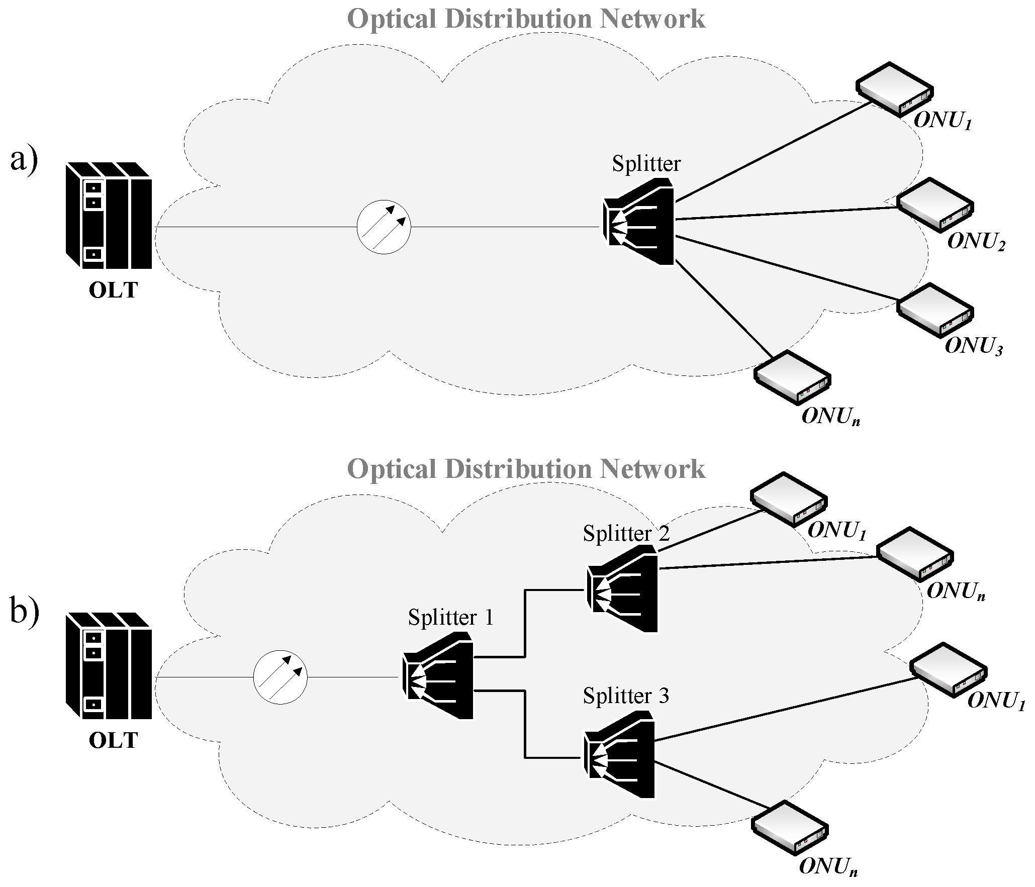
1. Introduction
2. PON Progress
- Active elements in network and fewer active devices lead to price reduction;
- No requirement for power suppliers or backup battery;
- Exigency optical-electrical-optical conversion for active devices that are not able to process data in the optical domain;
- Total bandwidth reduced due to additional active devices in network (passive technology does not require any other device).
2.1. APON
- Infrastructure and interfaces are application-independent;
- Full multiplexing/demultiplexing support;
- Effective handling of both variable and constant bit rates;
- Good support for delay-sensitive multimedia services;
- Simplified network management and operation;
- Promise of future security.
2.1.1. Historical Development of the APON Standard
2.1.2. Access Methods to Shared Media
2.1.3. Communication in APON
2.1.4. Dynamic Bandwidth Allocation
- Report without status;
- Status report itself;
- Hybrid report.
2.1.5. Deploying APON System
- 1990: British Telecom (APON);
- 1993: France Telecom (SAMPAN);
- 1993: Nippon Telegraph and Telephone;
- 1993: Siemens;
- 1994: European Commission (Broadband Access Facilities project).
- 1994: Bermuda, 100 connected entities;
- 1995: Great Britain, 2500 households joined;
- 1996: Belgium, 50 connected entities;
- 1996: France, 100 connected entities.
2.1.6. SuperPON
2.2. BPON
2.2.1. Historical Development of the BPON Standard
2.2.2. Deploying the BPON System
2.3. GPON
2.3.1. Communication in GPON
2.3.2. Dynamic Bandwidth Allocation
- Guaranteed fixed bandwidth for services sensitive to delay (VoD, VoIP);
- Guaranteed fixed bandwidth for services insensitive to delay (data transfer);
- Combination of fixed and dynamically allocated bandwidth (triple play services);
- Dynamic bandwidth allocation, the allocation is not guaranteed (best effort);
- Combination of all previously mentioned purposes.
2.3.3. Deploying the GPON System
2.4. XG-PON
2.4.1. History
2.4.2. Next-Generation PON
2.4.3. XG-PON1 and XG-PON2
- 1595–1615 nm: this range was rejected. The reason for this was the concern for the lack of specification of optical fibers and PON components for the associated wavelengths;
- 1540–1560 nm: this range was also rejected. The reason for this was incompatibility with the overlay video signal. Moreover, this range is used in most of the implemented PONs around the world;
- 1530–1540 nm: the reason for rejecting this range was the cost of ONU units’ acquisition for this particular range of wavelengths, as well as the fact that existing ONUs based on GPON technologies are unable to block this range;
- 1340–1360 nm: if this range is selected, a “coexistence” filter would be required. Nevertheless, such a filter would considerably increase the attenuation of the entire PON. For this reason, this particular range was also rejected.
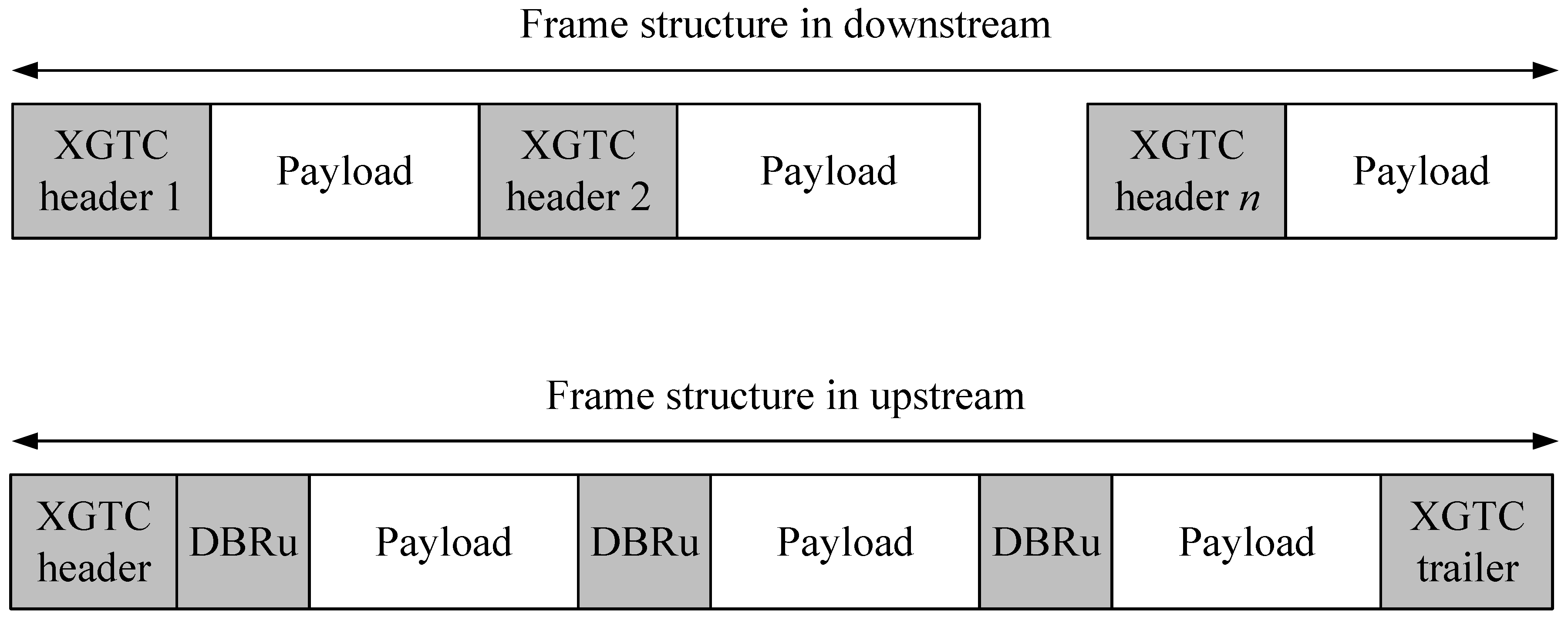
2.4.4. Communication in XG-PON
- Fixed-size part, which contains information about the length of the following parts of the header. It is ensured by header error correction (HEC);
- Bandwidth map (BWmap) is used to hold information about the allocated bandwidth for the given ONU unit;
- The last part is for dedicated transmission of PLOAM messages.
- Traffic marking through a 16-bit ID;
- Fragmentation;
- Ensuring privacy for transmitted data.
2.4.5. Deploying of XG-PON System
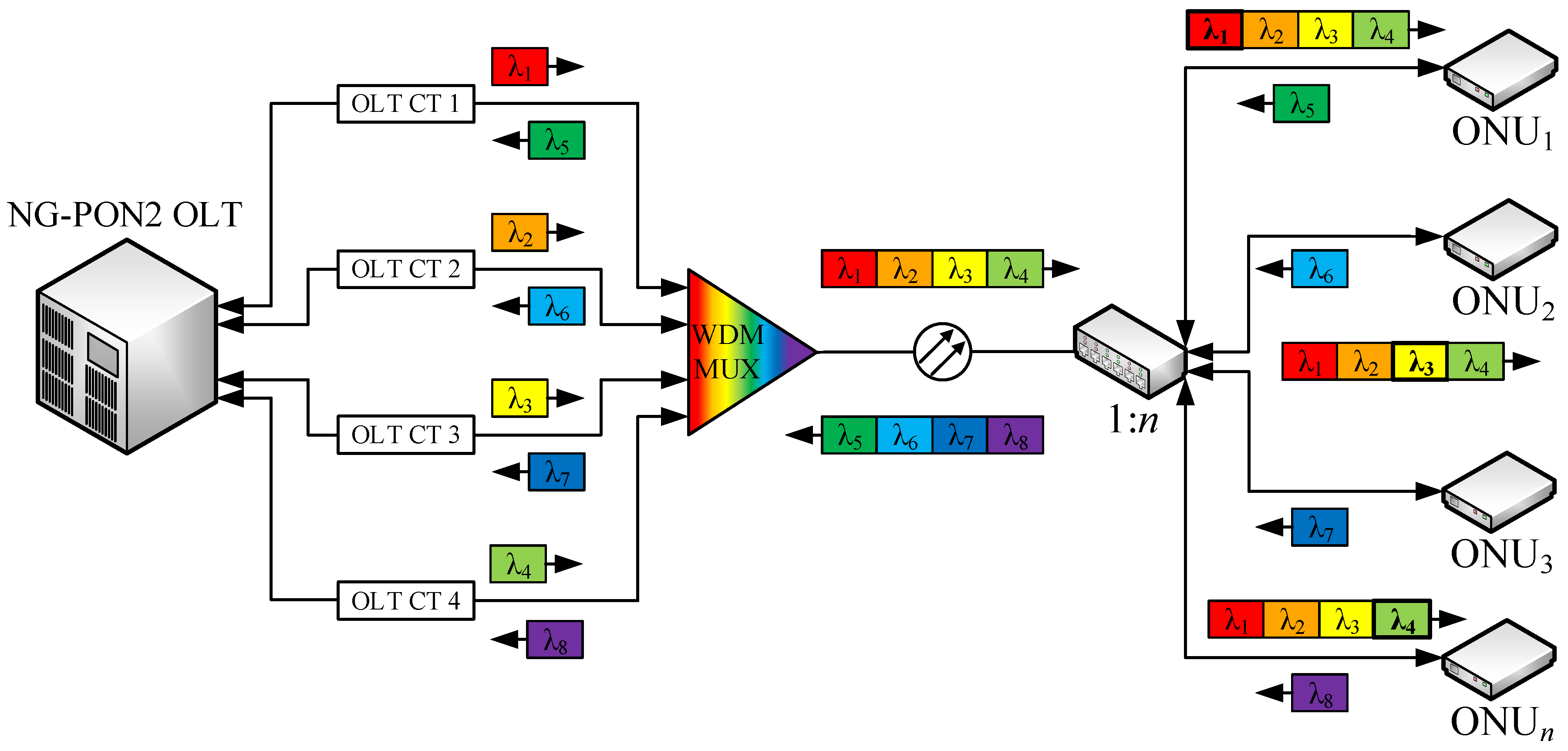
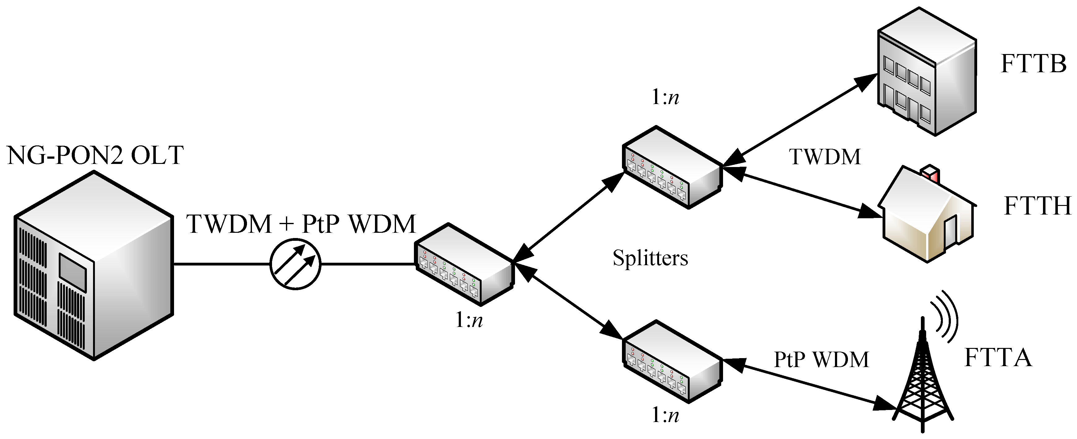
2.5. NG-PON2
2.5.1. History
- High financial efficiency;
- High capacity;
- Great reach and wide coverage;
- Effective allocation of network resources;
- Competitiveness;
- High energy efficiency.
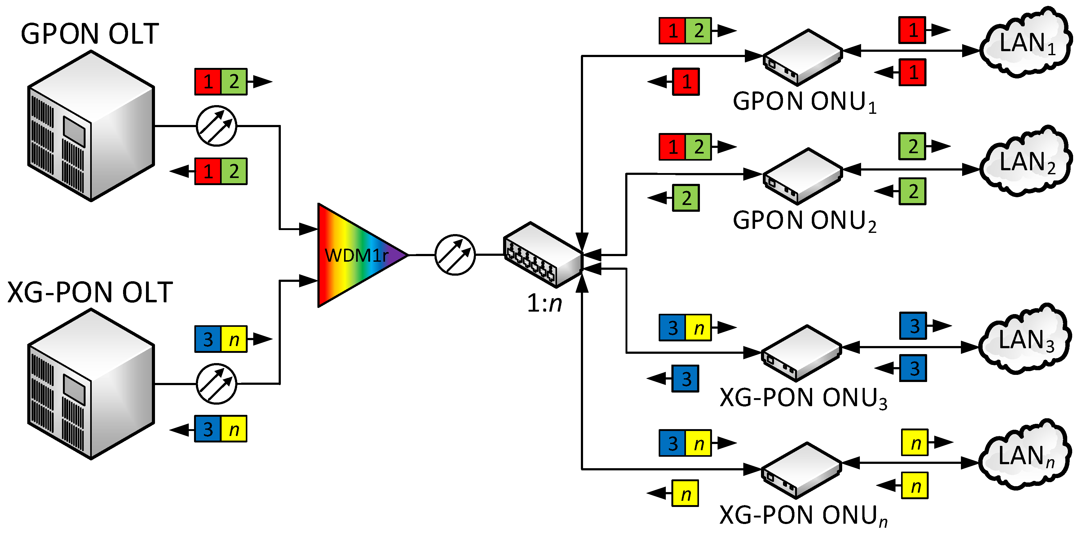
2.5.2. Coexistence
- Brownfield migration scenario;
- Greenfield migration scenario.
2.5.3. Communication
2.5.4. Deploying the NG-PON2 System
2.5.5. Future Development
3. Conclusions
Funding
Acknowledgments
Conflicts of Interest
Abbreviations
| ACTS | Advanced communication technologies and services |
| ADSL | Asymmetric digital subscriber line |
| APON | Asynchronous transfer mode passive optical network |
| ATM | Asynchronous transfer mode |
| AWG | Arrayed waveguide gratings |
| B-ISDN | Broadband integrated services digital network |
| BPON | Broadband passive optical network |
| BWmap | Bandwidth map |
| CAGR | Compound annual growth rate |
| CDM | Code division multiplexing |
| CDMA-PON | Code division multiple access passive optical network |
| DBA | Dynamic bandwidth allocation |
| DVB-T | Digital video broadcasting—terrestrial |
| EDFA | Erbium-doped fiber amplifier |
| EPON | Ethernet passive optical network |
| EU | European Union |
| FDM | Frequency-division multiplexing |
| FEC | Forward error correction |
| FSAN | Full service access network |
| FTTB | Fiber to the building |
| FTTC | Fiber to the cabinet/curb |
| FTTH | Fiber to the home |
| FTTx | Fiber to the x |
| GE | Gigabit Ethernet |
| GEM | Gigabit passive optical network encapsulation method |
| GPON | Gigabit passive optical network |
| HDTV | High-definition television |
| HEC | Header error correction |
| ICTP | Inter-channel termination protocol |
| IEEE | Institute of Electrical and Electronics Engineers |
| IoT | Internet of Things |
| IP | Internet protocol |
| IPTV | Internet protocol television |
| ISPs | Internet services providers |
| ITU | International Telecommunication Union |
| LO | Local oscillator |
| LTE | Long term evolution |
| NG | Next-generation |
| NG-PON2 | Next-generation passive optical network stage 2 |
| OAN | Optical access network |
| ODN | Optical distribution network |
| OFDM-PON | Orthogonal frequency division multiplex passive optical network |
| OLT | Optical line termination |
| ONT | Optical network termination |
| ONUs | Optical network units |
| OOK | On-off keying |
| P2MP | Point-to-multipoint |
| P2P | Point-to-point |
| PAM | Pulse-amplitude modulation |
| PCBd | Physical control block downstream |
| PLANET | Photonic local access network |
| PLOAM | Physical layer operation and administration and maintenance |
| PONs | Passive optical networks |
| POTS | Plain old telephone service |
| PSK | Phase-shift keying |
| QAM | Quadrature amplitude modulation |
| QoS | Quality of service |
| SDH | Synchronous digital hierarchy |
| SDN | Software defined network |
| SOA | Semiconductor optical amplifier |
| SONET | Synchronous optical network |
| T-CONT | Transmission container |
| T-PON | Telephony over passive optical network |
| TDM | Time division multiplexing |
| TDMA | Time division multiple access |
| TWDM | Time and wavelength division multiplexing |
| USA | United States of America |
| VNI | Visual networking index |
| VDSL | Very-high-speed digital subscriber line |
| VoD | Video on demand |
| VoIP | Voice over Internet protocol |
| WCDMA | Wideband code division multiple access |
| WDM | Wavelength division multiplex |
| WiFi | Wireless fidelity |
| WiMAX | Worldwide interoperability for microwave access |
| WWW | World wide web |
| XG-PON | Next-generation passive optical network |
| XGS-PON | Next-generation symmetrical passive optical network |
| XGTC | Next-generation passive optical network transmission convergence |
References
- Ford, G.S. Is Faster Better? Quantifying the Relationship Between Broadband Speed and Economic Growth. Telecommun. Policy 2018, 42, 766–777. [Google Scholar] [CrossRef]
- Steenbruggen, J.; Tranos, E.; Nijkamp, P. Data from Mobile Phone Operators: A Tool for Smarter Cities? Telecommun. Policy 2015, 39, 335–346. [Google Scholar] [CrossRef]
- Falch, M.; Henten, A. Dimensions of Broadband Policies and Developments. Telecommun. Policy 2018, 42, 715–725. [Google Scholar] [CrossRef]
- Hernandez, J.A.; Sanchez, R.; Martin, I.; Larrabeiti, D. Meeting The Traffic Requirements Of Residential Users In The Next Decade With Current Ftth Standards: How Much? How Long? IEEE Commun. Mag. 2019, 57, 120–125. [Google Scholar] [CrossRef]
- Vu Thang, N.; Dac Tung, V.; Duc Hoan, N. Architecture Of Integer Motion Estimation Hevc For Encoding 8K Video. In Proceedings of the 2017 International Conference on Advanced Technologies for Communications (ATC), Quy Nhon, Vietnam, 18–20 October 2017; pp. 279–284. [Google Scholar]
- Kim, Y.-H.; Huh, J.; Jeong, J. Distributed Video Transcoding System For 8K 360° Vr Tiled Streaming Service. In Proceedings of the 2018 International Conference on Information and Communication Technology Convergence (ICTC), Jeju, Korea, 17–19 October 2018; pp. 592–595. [Google Scholar]
- Cisco Annual Internet Report (2018–2023) White Paper. Available online: https://bit.ly/2X4s89S (accessed on 27 May 2020).
- Girard, A. Fttx Pon Technology and Testing; EXFO: Richardson, TX, USA, 2005. [Google Scholar]
- Forzati, M.; Mattsson, C. Socio-Economic Return of FTTH Investment in Sweden, a Prestudy. Available online: https://bit.ly/2XAp9oL (accessed on 27 May 2020).
- G.983.1: Broadband Optical Access Systems Based on Passive Optical Networks (PON). Available online: https://bit.ly/2AZscPE (accessed on 27 May 2020).
- Stern, J.R.; Ballance, J.W.; Faulkner, D.W.; Hornung, S.; Payne, D.B.; Oakley, K. Passive Optical Local Networks For Telephony Applications And Beyond. Electron. Lett. 1987, 23, 1255–1257. [Google Scholar] [CrossRef]
- Next Generation Access Networks (NGA): EUR Lex: Access to European Union Law. Available online: https://bit.ly/36zL03U (accessed on 28 May 2020).
- Google Fiber: Google Fiber | High Speed Internet Service & TV. Available online: https://fiber.google.com/ (accessed on 28 May 2020).
- AT&T: AT&T Fiber—Make High Speed Internet Even Faster. Available online: https://www.att.com/internet/fiber/ (accessed on 28 May 2020).
- Zhou, L.W.; Mas Machuca, C.; Zhao, R.; Grunert, K. Migration towards Fibre to the Home: Key Cost Factors. In Proceedings of the Asia Communications and Photonics Conference and Exhibition, Shanghai, China, 8–12 December 2010; pp. 399–400. [Google Scholar]
- Forzati, M.; Bianchi, A.; Chen, J.; Grobe, K.; Lannoo, B.; Machuca, C.M.; Point, J.-C.; Skubic, B.; Verbrugge, S.; Weis, E.; et al. Next-Generation Optical Access Seamless Evolution: Concluding Results Of The European Fp7 Project Oase. J. Opt. Commun. Netw. 2015, 7, 109–123. [Google Scholar] [CrossRef]
- Kim, K. On The Evolution of Pon-Based Ftth Solutions. Inf. Sci. 2003, 149, 21–30. [Google Scholar] [CrossRef]
- Van de Voorde, I.; Van der Plas, C. Full Service Optical Access Networks: Atm Transport On Passive Optical Networks. IEEE Commun. Mag. 1997, 35, 70–75. [Google Scholar] [CrossRef]
- Chanclou, P.; Gosselin, S.; Palacios, J.F.; Alvarez, V.L.; Zouganeli, E. Overview Of The Optical Broadband Access Evolution: A Joint Article By Operators In The Ist Network Of Excellence E-Photon/One. IEEE Commun. Mag. 2006, 44, 29–35. [Google Scholar] [CrossRef]
- Vetter, P.; Goderis, D.; Verpooten, L.; Granger, A. Systems Aspects Of Apon/Vdsl Deployment. IEEE Commun. Mag. 2000, 38, 66–72. [Google Scholar] [CrossRef]
- Ringoot, E.; Janssens, N.; Tassent, A.; Angeloupoulos, J.; Blondia, C.; Vetter, P. Demonstration Of Dynamic Medium Access Control For Apon And Superpon. In Proceedings of the GLOBECOM’01, IEEE Global Telecommunications Conference (Cat. No.01CH37270), San Antonio, TX, USA, 25–29 November 2001; pp. 1570–1574. [Google Scholar]
- James, K.A.; Fisher, S. Developments In Optical Access Networks. BT Technol. J. 2002, 20, 81–90. [Google Scholar] [CrossRef]
- Gagnaire, M.; Stojanovski, S. Stream Traffic Management Over An Atm Passive Optical Network. Comput. Netw. 2000, 32, 571–586. [Google Scholar] [CrossRef]
- Oakley, K.; Jensen, J.D.; Walkoe, W. British Telecom Tpon Application In The Us Network. In Proceedings of the IEEE Global Telecommunications Conference, 1989, and Exhibition. ’Communications Technology for the 1990s and Beyond, Dallas, TX, USA, 27–30 November 1989; pp. 1340–1345. [Google Scholar]
- Bickers, L.; Cade, I.; James, K.; James, S. Operations And Maintenance Experimental Testbed For A Business Tpon System. In Proceedings of the IEEE Global Telecommunications Conference GLOBECOM ’91: Countdown to the New Millennium. Conference Record, Phoenix, AZ, USA, 2–5 December 1991; pp. 569–571. [Google Scholar]
- Hossen, M.; Hanawa, M. Adaptive Limited Dba Algorithm For Multi-Olt Pon-Based Ftth And Wireless Sensor Networks. In Proceedings of the 2012 18th Asia-Pacific Conference on Communications (APCC), Jeju Island, Korea, 15–17 October 2012; pp. 372–377. [Google Scholar]
- Subramaniam, S. Emerging Optical Network Technologies: Architectures, Protocols and Performance; Sivalingam, K.M., Ed.; Springer: New York, NY, USA, 2005. [Google Scholar]
- Jang, J.; Park, E.K. Dynamic Resource Allocation for Quality of Service on A Pon with Home Networks. IEEE Commun. Mag. 2000, 38, 184–190. [Google Scholar] [CrossRef]
- G.984.3: Gigabit-Capable Passive Optical Networks (G-PON): Transmission Convergence Layer Specification. Available online: https://www.itu.int/rec/T-REC-G.984.3 (accessed on 28 May 2020).
- Van der Plas, G.; Smets, R.; Suard, B.; Verbiest, W. Demonstration of an Atm-Based Passive Optical Network in the Ftth Trial On Bermuda. In Proceedings of the GLOBECOM ’95, Singapore, 14–16 November 1995; pp. 988–992. [Google Scholar]
- Phillips, A.J. Reliability of Superpon Systems. In Proceedings of the Sixth IEE Conference on Telecommunications, Edinburgh, UK, 29 March–1 April 1998; pp. 219–223. [Google Scholar]
- G.983.3: A Broadband Optical Access System with Increased Service Capability by Wavelength Allocation. Available online: https://www.itu.int/rec/T-REC-G.983.3 (accessed on 28 May 2020).
- Filka, M. Optoelectronics for Telecommunications and Informatics; Optokon & Methode Electronic: Dallas, TX, USA, 2009. [Google Scholar]
- Mukherjee, B. Optical Wdm Networks; Optical Networks, from Physical Layer to Service Offerings; Springer: New York, NY, USA, 2006. [Google Scholar]
- Antoniades, N.N.; Ellinas, G.; Roudas, I. Wdm Systems and Networks: Modeling, Simulation, Design and Engineering; Springer: New York, NY, USA, 2012. [Google Scholar]
- Hood, D. Gigabit-Capable Passive Optical Networks; Wiley: Hoboken, NJ, USA, 2012. [Google Scholar]
- Lin, W.-P. Reducing Multiple Optical Carriers Interference in Broad-Band Passive Optical Networks. IEEE Photonics Technol. Lett. 1997, 9, 368–370. [Google Scholar] [CrossRef]
- Shumate, P.W. Fiber-To-The-Home: 1977–2007. J. Lightw. Technol. 2008, 26, 1093–1103. [Google Scholar] [CrossRef]
- Abrams, M.; Becker, P.C.; Fujimoto, Y.; O’Byrne, V.; Piehler, D. Fttp Deployments in the United States And Japan-Equipment Choices And Service Provider Imperatives. J. Lightw. Technol. 2005, 23, 236–246. [Google Scholar] [CrossRef]
- Gianordoli, S.; Rasztovits-Wiech, M.; Stadler, A.; Grabenhorst, R. Next Generation Pon. Elektrotechnik und Informationstechnik 2006, 123, 78–82. [Google Scholar] [CrossRef]
- G.984.1: Gigabit-Capable Passive Optical Networks (GPON): General Characteristics. Available online: https://www.itu.int/rec/T-REC-G.984.1-200803-I/en (accessed on 28 May 2020).
- G.984.2: Gigabit-Capable Passive Optical Networks (G-PON): Physical Media Dependent (PMD) Layer Specification. Available online: https://www.itu.int/rec/T-REC-G.984.2-201908-I/en (accessed on 28 May 2020).
- Cale, I.; Salihovic, A.; Ivekovic, M. Gigabit Passive Optical Network—Gpon. In Proceedings of the 2007 29th International Conference on Information Technology Interfaces, Cavtat, Croatia, 25–28 June 2007; pp. 679–684. [Google Scholar]
- Abbas, H.S.; Gregory, M.A. The Next Generation of Passive Optical Networks: A Review. J. Netw. Comput. Appl. 2016, 67, 53–74. [Google Scholar] [CrossRef]
- Skubic, B.; Chen, J.; Ahmed, J.; Wosinska, L.; Mukherjee, B. A Comparison of Dynamic Bandwidth Allocation for Epon, Gpon, and Next-Generation Tdm Pon. IEEE Commun. Mag. 2009, 47, S40–S48. [Google Scholar] [CrossRef]
- Jiang, J.; Handley, M.R.; Senior, J.M. Dynamic Bandwidth Assignment Mac Protocol for Differentiated Services over Gpon. Electron. Lett. 2006, 42, 653–655. [Google Scholar] [CrossRef]
- Qiu, X.-Z.; Ossieur, P.; Bauwelinck, J.; Yi, Y.; Verhulst, D.; Vandewege, J.; DeVos, B.; Solina, P. Development of Gpon Upstream Physical-Media-Dependent Prototypes. J. Lightw. Technol. 2004, 22, 2498–2508. [Google Scholar] [CrossRef]
- Weis, E.; Hölzl, R.; Breuer, D.; Lange, C. Gpon Ftth Trial—Lessons Learned. In Proceedings of the 2009 Asia Communications and Photonics conference and Exhibition (ACP), Shanghai, China, 2–6 November 2009; p. 76330J-1-7. [Google Scholar]
- G.987.1: 10-Gigabit-Capable Passive Optical Networks (XG-PON): General Requirements. Available online: https://www.itu.int/rec/T-REC-G.987.1-201603-I/en (accessed on 28 May 2020).
- Wong, E. Next-Generation Broadband Access Networks and Technologies. J. Lightw. Technol. 2012, 30, 597–608. [Google Scholar] [CrossRef]
- Effenberger, F.J. Industrial Trends and Roadmap of Access. J. Lightw. Technol. 2017, 35, 1142–1146. [Google Scholar] [CrossRef]
- Chen, L.; Dahlfort, S.; Hood, D. Evolution of Pon: 10G-Pon and Wdm-Pon. In Proceedings of the Asia Communications and Photonics Conference and Exhibition, Shanghai, China, 8–12 December 2010; pp. 709–711. [Google Scholar]
- Hajduczenia, M.; da Silva, H.J.A. Next Generation Pon Systems—Current Status. In Proceedings of the 2009 11th International Conference on Transparent Optical Networks, Azores, Portugal, 28 June–2 July 2009; pp. 1–8. [Google Scholar]
- Jain, S.; Effenberger, F.; Szabo, A.; Feng, Z.; Forcucci, A.; Guo, W.; Luo, Y.; Mapes, R.; Zhang, Y.; O’Byrne, V. World’s First Xg-Pon Field Trial. J. Lightw. Technol. 2011, 29, 524–528. [Google Scholar] [CrossRef]
- G.984.5: Gigabit-Capable Passive Optical Networks (G-PON): Enhancement Band. Available online: https://www.itu.int/rec/T-REC-G.984.5-201405-I/en (accessed on 28 May 2020).
- Effenberger, F.J. The Xg-Pon System: Cost Effective 10 Gb/S Access. J. Lightw. Technol. 2011, 29, 403–409. [Google Scholar] [CrossRef]
- Muciaccia, T.; Gargano, F.; Passaro, V. Passive Optical Access Networks: State of the Art and Future Evolution. Photonics 2014, 1, 323–346. [Google Scholar] [CrossRef]
- G.9807.1: 10-Gigabit-Capable Symmetric Passive Optical Network (XGS-PON). Available online: https://www.itu.int/rec/T-REC-G.9807.1/en (accessed on 2 June 2020).
- G.987.3: 10-Gigabit-Capable Passive Optical Networks (XG-PON): Transmission Convergence (TC) Layer Specification. Available online: https://www.itu.int/rec/T-REC-G.987.3/en (accessed on 2 June 2020).
- Li, C.; Guo, W.; Wang, W.; Hu, W.; Xia, M. Bandwidth Resource Sharing On The Xg-Pon Transmission Convergence Layer In A Multi-Operator Scenario. J. Opt. Commun. Netw. 2016, 8, 835–843. [Google Scholar] [CrossRef]
- Yiannopoulos, K.; Varvarigos, E.A.; Papadimitriou, G.; Gravalos, I. Burst-By-Burst Dynamic Bandwidth Allocation For Xg-Pons. IET Netw. 2016, 5, 47–55. [Google Scholar] [CrossRef]
- G.989.1: 40-Gigabit-Capable Passive Optical Networks (NG-PON2): General Requirements. Available online: https://www.itu.int/rec/T-REC-G.989.1/e (accessed on 2 June 2020).
- Chen, X.; Zhang, Z.; Hu, X. The Evolution Trends of Pon and Key Techniques for Ng-Pon. In Proceedings of the 9th International Conference on Information, Communications & Signal Processing, Tainan, Taiwan, 10–13 December 2013; pp. 1–6. [Google Scholar] [CrossRef]
- Digital Czech Republic v. 2.0—The Way to the Digital Economy. Available online: https://bit.ly/2DGiEYn (accessed on 2 June 2020).
- G.989.2: 40-Gigabit-Capable Passive Optical Networks 2 (NG-PON2): Physical Media Dependent (PMD) Layer Specification. Available online: https://www.itu.int/rec/T-REC-G.989.2-201902-I/en (accessed on 2 June 2020).
- Nesset, D. Ng-Pon2 Technology and Standards. J. Lightw. Technol. 2015, 33, 1136–1143. [Google Scholar] [CrossRef]
- Khotimsky, D.A. Ng-Pon2 Transmission Convergence Layer: A Tutorial. J. Lightw. Technol. 2016, 34, 1424–1432. [Google Scholar] [CrossRef]
- G.989.3: 40-Gigabit-Capable Passive Optical Networks (NG-PON2): Transmission Convergence Layer Specification. Available online: https://www.itu.int/rec/T-REC-G.989.3/en (accessed on 2 June 2020).
- Wey, J.S.; Nesset, D.; Valvo, M.; Grobe, K.; Roberts, H.; Luo, Y.; Smith, J. Physical Layer Aspects of Ng-Pon2 Standards-Part 1: Optical Link Design [Invited]. J. Opt. Commun. Netw. 2016, 8, 33–42. [Google Scholar] [CrossRef]
- Luo, Y.; Roberts, H.; Grobe, K.; Valvo, M.; Nesset, D.; Asaka, K.; Rohde, H.; Smith, J.; Wey, J.S.; Effenberger, F. Physical Layer Aspects Of Ng-Pon2 Standards-Part 2: System Design And Technology Feasibility [Invited]. J. Opt. Commun. Netw. 2016, 8, 43–52. [Google Scholar] [CrossRef]
- Luo, Y.; Zhou, X.; Effenberger, F.; Yan, X.; Peng, G.; Qian, Y.; Ma, Y. Time- and Wavelength-Division Multiplexed Passive Optical Network (Twdm-Pon) For Next-Generation Pon Stage 2 (Ng-Pon2). J. Lightw. Technol. 2013, 31, 587–593. [Google Scholar] [CrossRef]
- Lau, M.F.; Vetter, P.; Deppisch, B.; Farah, B.; Phlmann, W.; Duque, A.; Galaro, J.; van Veen, D.; Pfeiffer, T. System Demonstration of a Time and Wavelength-Set Division Multiplexing Pon. In Proceedings of the 39th European Conference and Exhibition on Optical Communication (ECOC 2013), Institution of Engineering and Technology, London, UK, 22–26 September 2013; pp. 564–566. [Google Scholar]
- Verizon, Calix Deploy Commercial NG-PON2. Available online: https://bit.ly/2MRO2sW (accessed on 2 June 2020).
- Nesset, D. Pon Roadmap [Invited]. J. Opt. Commun. Netw. 2017, 9, A71–A76. [Google Scholar] [CrossRef]
- Sugie, T.; Nakamura, H. Recent Advances In Access Networks And Their Components Technologies. In Proceedings of the 2015 International Conference on Microwave and Photonics (ICMAP), Dhanbad, India, 11–13 December 2015; pp. 1–2. [Google Scholar]
- Bourg, K.; Ten, S.; Whitman, R.; Jensen, J.; Diaz, V. The Evolution of Outside Plant Architectures Driven By Network Convergence And New Pon Technologies. In Proceedings of the 2017 Optical Fiber Communications Conference and Exhibition (OFC), Los Angeles, CA, USA, 19–23 March 2017; pp. 1–3. [Google Scholar]
- Lach, E.; Idler, W. Modulation formats for 100G and beyond. Opt. Fiber Technol. 2011, 17, 377–386. [Google Scholar] [CrossRef]
- Dong-Nhat, N.; Elsherif, M.A.; Malekmohammadi, A. Investigations of high-speed optical transmission systems employing Absolute Added Correlative Coding (AACC). Opt. Fiber Technol. 2016, 30, 23–31. [Google Scholar] [CrossRef]
- Houtsma, V.; van Veen, D.; Chow, H. Demonstration of Symmetrical 25 Gb/s TDM-PON With Multilevel Interleaving of Users. J. Lightw. Technol. 2016, 34, 2005–2010. [Google Scholar] [CrossRef]
- Jung, S.P.; Cho, K.Y.; Takushima, Y.; Chung, Y.C. Recent progresses in coherent WDM PON technologies. In Proceedings of the 2010 12th International Conference on Transparent Optical Networks, Munich, Germany, 27 June–1 July 2010; p. 1. [Google Scholar]
- Tabares, J.; Ghasemi, S.; Polo, V.; Prat, J. Simplified Carrier Recovery for Intradyne Optical PSK Receivers in udWDM-PON. J. Lightw. Technol. 2018, 36, 2941–2947. [Google Scholar] [CrossRef]
- Li, Z.; Dong, Y.; Wang, Y.; Lu, C. A novel PSK-manchester Modulation format in 10-gb/s passive optical network system with high tolerance to beat interference noise. IEEE Photonics Technol. Lett. 2005, 17, 1118–1120. [Google Scholar] [CrossRef]
- Xiao, Q.; Chen, Y.; Lin, S.; He, H.; Wu, X.; You, J.; Zeng, Y.; Zhou, L.; Dong, Z. DFT-Spread DMT-WDM-PON Employing LDPC-Coded Probabilistic Shaping 16 QAM. J. Lightw. Technol. 2020, 38, 714–722. [Google Scholar] [CrossRef]
- Pittala, F.; Cano, I.N.; Bluemm, C.; Schaedler, M.; Calabro, S.; Goeger, G.; Brenot, R.; Xie, C.; Shi, C.; Liu, G.N.; et al. 400-Gbit/s DP-16-QAM Transmission Over 40-km Unamplified SSMF With Low-Cost PON Lasers. IEEE Photonics Technol. Lett. 2019, 31, 1229–1232. [Google Scholar] [CrossRef]
- Lazarou, I.; Dris, S.; Bakopoulos, P.; Schrenk, B.; Avramopoulos, H. Full-Duplex 4-PAM Transmission for Capacity Upgrade in Loop-Back PONs. IEEE Photonics Technol. Lett. 2013, 25, 1125–1128. [Google Scholar] [CrossRef]
- Stamatiadis, C.; Matsumoto, R.; Yoshida, Y.; Agata, A.; Maruta, A.; Kitayama, K.-I. Full-Duplex RSOA-Based PONs Using 4-PAM With Pre-Equalization. IEEE Photonics Technol. Lett. 2015, 27, 73–76. [Google Scholar] [CrossRef]
- Wei, J.L.; Grobe, K.; Griesser, H. High speed next generation passive optical networks: Performance, cost, and power dissipation. In Proceedings of the 2016 Progress in Electromagnetic Research Symposium (PIERS), Shanghai, China, 8–11 August 2016; pp. 4856–4857. [Google Scholar]
- Sales, V.; Segarra, J.; Polo, V.; Velásquez, J.C.; Prat, J. UDWDM-PON Using Low-Cost Coherent Transceivers With Limited Tunability and Heuristic DWA. J. Opt. Commun. Netw. 2016, 8, 582–599. [Google Scholar] [CrossRef]
- Tamai, H.; Sarashina, M.; Iwamura, H.; Kashima, M.; Gupta, G.C.; Ushikubo, T.; Kamijoh, T.; Chanclou, P.; Genay, N.; Landousies, B.; et al. First Demonstration of Coexistence of Standard Gigabit TDM-PON and Code Division Multiplexed PON Architectures Toward Next Generation Access Network. J. Lightw. Technol. 2009, 27, 292–298. [Google Scholar] [CrossRef]
- Kashima, M.; Gupta, G.C.; Iwamura, H.; Tamai, H.; Watanabe, R.; Ushikubo, T.; Kamijoh, T. 42-dB loss budget hybrid DWDM-CDM-PON without optical amplifier. Electron. Lett. 2007, 43, 49–50. [Google Scholar] [CrossRef]
- Yin, H.; Richardson, D.J. Optical Code Division Multiple Access Communication Networks: Theory and Applications; Springer: Berlin/Heidelberg, Germany, 2009; p. 382. [Google Scholar]
- Shieh, W.; Djordjevic, I. OFDM for Optical Communications; Academic Press: Cambridge, MA, USA, 2009; p. 456. [Google Scholar]
- Yu, J.; Huang, M.-F.; Qian, D.; Chen, L.; Chang, G.-K. Centralized Lightwave WDM-PON Employing 16-QAM Intensity Modulated OFDM Downstream and OOK Modulated Upstream Signals. IEEE Photonics Technol. Lett. 2008, 20, 1545–1547. [Google Scholar] [CrossRef]
- Cano, I.N.; Escayola, X.; Schindler, P.C.; Santos, M.C.; Polo, V.; Leuthold, J.; Tomkos, I.; Prat, J. Experimental Demonstration of a Statistical OFDM-PON With Multiband ONUs and Elastic Bandwidth Allocation [Invited]. J. Opt. Commun. Netw. 2015, 7, A73–A79. [Google Scholar] [CrossRef]
- Yang, H.; Li, J.; Lin, B.; Wan, Y.; Guo, Y.; Zhu, L.; Li, L.; He, Y.; Chen, Z. DSP-Based Evolution From Conventional TDM-PON to TDM-OFDM-PON. J. Lightw. Technol. 2013, 31, 2735–2741. [Google Scholar] [CrossRef]
- Chen, H.-Y.; Wei, C.-C.; Lu, I.-C.; Chu, H.-H.; Chen, Y.-C.; Chen, J. High-Capacity and High-Loss-Budget OFDM Long-Reach PON Without an Optical Amplifier [Invited]. J. Opt. Commun. Netw. 2015, 7, A59–A65. [Google Scholar] [CrossRef]
- Yoshimoto, N.; Kani, J.-I.; Kim, S.-Y.; Iiyama, N.; Terada, J. DSP-based optical access approaches for enhancing NG-PON2 systems. IEEE Commun. Mag. 2013, 51, 58–64. [Google Scholar] [CrossRef]
- Birk, M.; Gerard, P.; Curto, R.; Nelson, L.; Zhou, X.; Magill, P.; Schmidt, T.J.; Malouin, C.; Zhang, B.; Ibragimov, E.; et al. Coherent 100 Gb/s PM-QPSK field trial. IEEE Commun. Mag. 2010, 48, 52–60. [Google Scholar] [CrossRef]
- Nosu, K. Advanced coherent lightwave technologies. IEEE Commun. Mag. 1988, 26, 15–21. [Google Scholar] [CrossRef]
- Semrau, D.; Xu, T.; Shevchenko, N.A.; Paskov, M.; Alvarado, A.; Killey, R.I.; Bayvel, P. Achievable information rates estimates in optically amplified transmission systems using nonlinearity compensation and probabilistic shaping. Opt. Lett. 2017, 42, 121–124. [Google Scholar] [CrossRef] [PubMed]
- Dong-Nhat, N.; Nguyen, L.; Malekmohammadi, A. Using duobinary with first- and second-order optical equalisers for extending transmission distance of optical access networks. IET Optoelectron. 2018, 12, 239–243. [Google Scholar] [CrossRef]
- Teixeira, A.; Lavery, D.; Ciaramella, E.; Schmalen, L.; Iiyama, N.; Ferreira, R.M.; Randel, S. DSP Enabled Optical Detection Techniques for PON. J. Lightw. Technol. 2020, 38, 684–695. [Google Scholar] [CrossRef]
- Cho, K.Y.; Tanaka, K.; Sano, T.; Jung, S.P.; Chang, J.H.; Takushima, Y.; Agata, A.; Horiuchi, Y.; Suzuki, M.; Chung, Y.C. Long-Reach Coherent WDM PON Employing Self-Polarization-Stabilization Technique. J. Lightw. Technol. 2011, 29, 456–462. [Google Scholar] [CrossRef]
- Suzuki, N.; Miura, H.; Matsuda, K.; Matsumoto, R.; Motoshima, K. 100 Gb/s to 1 Tb/s Based Coherent Passive Optical Network Technology. J. Lightw. Technol. 2018, 36, 1485–1491. [Google Scholar] [CrossRef]
- Matsuda, K.; Suzuki, N. Hardware-Efficient Signal Processing Technologies for Coherent PON Systems. J. Lightw. Technol. 2019, 37, 1614–1620. [Google Scholar] [CrossRef]
- Koma, R.; Fujiwara, M.; Kani, J.-I.; Suzuki, K.-I.; Otaka, A. Burst-Mode Digital Signal Processing That Pre-Calculates FIR Filter Coefficients for Digital Coherent PON Upstream. J. Opt. Commun. Netw. 2018, 10, 461–470. [Google Scholar] [CrossRef]
- Kim, S.-Y.; Kani, J.-I.; Terada, J. Performance Analysis of Phase Noise Cancellation by Asymmetric CMA for Realizing Affordable Coherent PON Transceivers. J. Lightw. Technol. 2020, 38, 2231–2241. [Google Scholar] [CrossRef]
- Zhang, J.; Guo, C.; Liu, J.; Wu, X.; Lau, A.P.T.; Lu, C.; Yu, S. Decision-Feedback Frequency-Domain Volterra Nonlinear Equalizer for IM/DD OFDM Long-Reach PON. J. Lightw. Technol. 2019, 37, 3333–3342. [Google Scholar] [CrossRef]
- Xu, T.; Liga, G.; Lavery, D.; Thomsen, B.C.; Savory, S.J.; Killey, R.I.; Bayvel, P. Equalization enhanced phase noise in Nyquist-spaced superchannel transmission systems using multi-channel digital back-propagation. Sci. Rep. 2015, 5, 1–13. [Google Scholar] [CrossRef] [PubMed]
- van Veen, D.T.; Houtsma, V.E. Proposals for Cost-Effectively Upgrading Passive Optical Networks to a 25G Line Rate. J. Lightw. Technol. 2017, 35, 1180–1187. [Google Scholar] [CrossRef]


| Bandwidth [Gb/s] | Split Ratio | Distance [km] | Attenuation [dB] |
|---|---|---|---|
| 40/40 | 1:256 | 25 | 31 |
| 40/40 | 1:1000 | 40 | 39 |
| 40/40 | 1:1024 | 50 | 43 |
| 40/40 | 1:256 | 75 | - |
| 40/40 | 1:46 | 100 | - |
| 100/100 | 1:1024 | 25 | 42 |
| 40/10 | 1:64 | 20 | 36 |
| Standard/Recommendation | APON | BPON | GPON | XG-PON | NG-PON2 |
|---|---|---|---|---|---|
| Approved | 1998 | 2001 | 2003 | 2010 | 2013 |
| ITU family | G.983 | G.983 | G.984 | G.987 | G.989 |
| Line code | NRZ (OOK) | NRZ (OOK) | NRZ (OOK) | NRZ (OOK) | NRZ (OOK) |
| Traffic mode | ATM | ATM | GEM | X-GEM | X-GEM |
| Transmission medium | G.652 | G.652 | G.652 | G.652/G.657 | G.652/G.657 |
| Wavelength range for downstream | 1480–1580 nm | 1480–1580 nm | 1480–1500 nm | 1575–1580 nm | 1596–1603 nm |
| Wavelength range for upstream | 1260–1360 nm | 1260–1360 nm | 1260–1360 nm | 1260–1280 nm | 1524–1544 nm (wide band option) 1528–1540 nm (reduced band option) 1532–1540 nm (narrow band option) |
| Transmission speed downstream | 622 Mb/s | up to 1244.16 Mb/s | up to 2488.32 Mb/s | up to 9953.28 Mb/s | up to 9953.28 Mb/s |
| Transmission speed upstream | 155 Mb/s | up to 622 Mb/s | up to 1244.16 Mb/s | up to 2488.32 Mb/s | up to 9953.28 Mb/s |
| Split ratio | up to 1:32 | up to 1:32 | up to 1:64 | up to 1:256 | over 1:256 |
© 2020 by the authors. Licensee MDPI, Basel, Switzerland. This article is an open access article distributed under the terms and conditions of the Creative Commons Attribution (CC BY) license (http://creativecommons.org/licenses/by/4.0/).
Share and Cite
Horvath, T.; Munster, P.; Oujezsky, V.; Bao, N.-H. Passive Optical Networks Progress: A Tutorial. Electronics 2020, 9, 1081. https://doi.org/10.3390/electronics9071081
Horvath T, Munster P, Oujezsky V, Bao N-H. Passive Optical Networks Progress: A Tutorial. Electronics. 2020; 9(7):1081. https://doi.org/10.3390/electronics9071081
Chicago/Turabian StyleHorvath, Tomas, Petr Munster, Vaclav Oujezsky, and Ning-Hai Bao. 2020. "Passive Optical Networks Progress: A Tutorial" Electronics 9, no. 7: 1081. https://doi.org/10.3390/electronics9071081
APA StyleHorvath, T., Munster, P., Oujezsky, V., & Bao, N.-H. (2020). Passive Optical Networks Progress: A Tutorial. Electronics, 9(7), 1081. https://doi.org/10.3390/electronics9071081