Article

Novel Efficacious Utilization of Fuzzy-Logic Controller-Based Two-Quadrant Operation of PMBLDC Motor Drive Systems for Multipass Hot-Steel Rolling Processes

by
Mohanraj Nandakumar
1,*,
Sankaran Ramalingam
1,
Subashini Nallusamy
1 and
Shriram Srinivasarangan Rangarajan
1,2,*
1
Department of EEE, SASTRA Deemed to be University, Thanjavur, Tamil Nadu 613401, India
2
Department of Electrical & Computer Engineering, Clemson University, Clemson, SC 29634, USA
*
Authors to whom correspondence should be addressed.
Electronics 2020, 9(6), 1008; https://doi.org/10.3390/electronics9061008
Submission received: 8 May 2020 / Revised: 11 June 2020 / Accepted: 13 June 2020 / Published: 16 June 2020
(This article belongs to the Special Issue Industrial Applications of Power Electronics)

Abstract

:
This study investigates the rough steel-rolling process, which requires repeated and rapid bidirectional hot-rolling operations and proposes a fuzzy-logic-controller-based brushless electric DC (BLDC) motor drive system for the same. We present a modeling of the hot-steel rough-rolling process using a set of metallurgical parameters and mechanical equations based on their operating conditions, specific features and characteristics, all obtained from actual data. The above equations and related parameters were modeled in MATLAB/Simulink schematic under variations in temperature and slab thickness corresponding using three different hot-rolled (HR) steel specimens. This led to the creation of a pair of speed and torque- profiles with alternate polarities for successive passes covering the entire rolling process for each steel specimen. A fuzzy logic controller utilized the above profiles on the motor shaft by incorporating speed and current feedback loops to attain reference speed and calculation of instantaneous stator currents of the BLDC motor with respective phase sequences, so as to satisfy the torque-profile. Simulation results showing the detailed performance of the drive system are presented. Further, experimental work on a BLD-motor-drive system is presented, along with loading arrangements and an arm controller embedded with control algorithm for the multi-loop feedback system used for the closed loop speed control. The efficacy of the new applications proposed in this study for the first time can be seen from the validation of the results from the BLDC motor with its fuzzy-based controller in terms of simulation and hardware, thereby serving to be an attractive alternative to conventional induction motor drive systems for steel rolling.

1. Introduction

The process of steel making is highly power-intensive. About eight percent of total energy consumption is required in hot-steel rolling. Steel products in the form of steel plates, welded pipes and wired products are utilized by various industries, such as automobiles, ship building and constructional areas. The first stage in hot rolling is the rough-rolling mill where steel ingots are rolled to produce products like slabs [1]. Stages use these intermediate specimens for production of plates or bars or rods and similar products. Prior to the above two phases of rolling, the incoming hot steel slab specimen must be surface-cleansed by scrubbing to remove layers of oxides.
The rolling process consists of a set of work and backup rolls driven by two identical high-power electric motors through a set of gear train arrangements. Each backup roll is driven by an individual drive system, such that the two work rolls rotate in opposite directions for forward/reverse feeding of the work piece at hand. The mechanical calculations [2] of rolling force and torque at the rollers for multipass operation involve taking into account various metallurgical properties and physical parameters of roll material, work temperature and roller dimensions. The rough-rolling process is aimed at successive reduction of thickness over multiple passes of rolling. Calculations over repeated forward-reverse rolling passes leads to the creation of profiles that define a series of operating points of the drive motors, in terms of shaft speed and developed torque.
Different from conventional DC electric motors, AC synchronous motors and induction motors, a new entrant is the permanent magnet brushless DC (PMBLDC) motor [3,4,5], which possess certain advantages like a high torque-to-current ratio, a high power-to-weight ratio as well as a quick response to load fluctuations and speed reversal. PMBLDC motors can operate over a wide range of speeds efficiently, while delivering nearly-full-load-rated torque and are amendable to precise control using feedback signals.
A significant contribution has been made [6] regarding the quick achievement of downloading an algorithm onto the controller board being used, but the output waveforms quick settlement in steady state has not achieved. One can read the study [7] concerned with proportional integral derivative (PID) self-tuning and model reference adaptive control, but it is not focused on experimental implementation. The main focus of this study [8] is incorporation of fuzzy PID for a closed-loop speed control, but it was utilized only for speed control-not on inner-current-control required for torque control. This study is focused on achieving both better torque and speed control in steady state, as well as several power electronic devices involved in hardware implementation.
In this study, the multipass rolling process of hot rough-steel-rolling milling was mathematically modeled starting with basic set of equations, characterized by draft, roller contact length, temperature dependent strength coefficient and strain-hardening exponent. The above model was integrated with a motor drive system through reduction gears and alternate control algorithms using speed and current feedback. An intelligent computing technique called fuzzy logic control was implemented for controlling the BLDC motor drive system [9,10,11,12,13]. Several controllers like conventional PI whose parameter values were selected by trial and error approach—and a tuned PI controller whose parameter values were selected by using Ziegler-Nichols approach—were also tested. Later, a comparison of all three controllers was done to ensure the quickness in reaching the steady state among the controllers. The overall drive system was simulated in the MATLAB/Simulink platform for performance evaluation. This work was carried out for multipass, bidirectional rolling of 3 different HR steel materials. It was found that the rolling operation closely follows the respective work profile. The performance of the drive system covering variables like motor shaft speed, electromagnetic torque, back-EMF and stator currents were evaluated for ten passes of hot-steel rolling over a duration of ten seconds, and the simulation results are presented. An experimental setup for speed control of the entire drive system was developed and the control algorithm for implementing the same was embedded as hex file on the arm microcontroller. The arm microcontroller calculated the speed error based on reference input profile values and actual output speed values sensed from the BLDC motor and provided necessary control action based on the developed control algorithm. Thereby, it regulated the speed of the BLDC motor.
This study is organized as follows. Section 2 describes the model of a hot-roughing steel-rolling mill. In Section 3 the profiles created for the rolling operation are discussed. The Section 4 deals with the mathematical model developed for the BLDC motor. In Section 5 the design of a fuzzy-logic controller employed for BLDC motor is introduced. In Section 6 the controller configuration with feedback design is incorporated. In Section 7 simulation schematic is dealt with. Section 8 describes experimental set up for the simulations created in simulation schematic. Finally, in Section 9 the results are discussed in the conclusion.

2. Model of A Hot-Roughing Steel-Rolling Mill

A hot-roughing steel-rolling mill is formed by integrating several mechanical components to produce the desired forces and forward movement of roll material for thickness reduction of incoming steel slabs. A typical hot-strip mill stand employs two identical BLDC motor drive systems coupled to a hot-roughing steel-rolling mill through reduction gears on either side (Figure 1). The work described in this study assumes multipass rolling, in which the hot material specimen is compressed between two work rolls, and each alternate pass is for a duration of one second—either in forward and reverse direction—over a total run of ten passes to obtain the desired reduction in thickness from an initial thickness ( t o ) to final thickness ( t f ) by the lamination force of the two parallel rolls.
A simplified schematic portraying the modeling of BLDC motor drive system incorporating speed and current feedback loops using fuzzy controller is shown in Figure 2. The essential components taking part in the rolling operation are a pair of work rolls, backup rolls and a gear train operated by a pair of BLDC motors. For simplicity, the power transmission from one BLDC motor alone is shown in Figure 2. In actual practice, another identical motor drive system is available to operate the work roller and back up roller on the opposite side of the work piece.
The electrical components of the system consist of three phased AC sources, three phase-uncontrolled bridge rectifiers, a 6-pulse inverter, a 4-pole BLDC motor and a speed error loop, along with reference torque and reference current generation modules, which are implemented by using fuzzy logic-based control algorithm [14,15,16,17,18,19,20,21,22,23,24].

2.1. Mathematical Modeling of Steel Rolling Process

Draft is a term specified for thickness reduction in steel-material rolling under specified operating conditions from hot slab to steel plates. This phenomenon—otherwise known as deformation—is governed by the following Equation (1):
d   = t o     t f = 2 R   ( 1   cos α )
where d = draft, mm, t o = initial thickness, mm and t f = final thickness, mm, R = roll radius, mm and α = bite angle in degrees.
The true strain experienced by the work piece while rolling is based on the thickness of the work material before and after rolling and is given by the Equation (2):
ε = ln ( t o t f )
During flat rolling, average flow stress Y f ¯ on the work material can be determined by the following Equation (3):
Y f ¯ = K ε n 1 + n
where K = strength coefficient, MPa and n = strain-hardening exponent.
The contact length L in mm is related to the rolling operation is defined as in Equation (4):
L   = [ R   ( t o     t f ) ] 0.5
Roll force F required for flat rolling is estimated by the following relation (5):
F   = Y f ¯ w   ×   L
where w = width of the steel slab, mm
In hot rolling, load torque required on each work roll is given by the Equation (6):
T = 0.5FL N-m
The PMBLDC motor is coupled to the steel-rolling system through an arrangement of reduction gears. The material properties and operational parameters of the rolling process are discussed in Section 2.2.

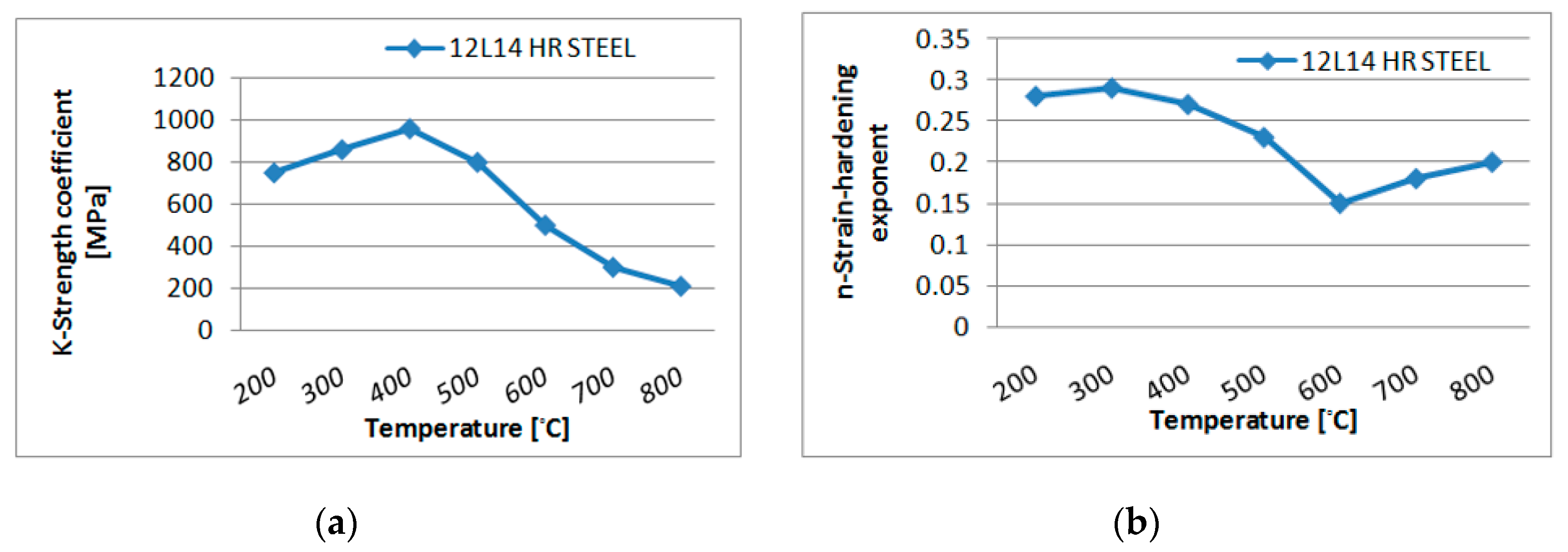
2.2. Rolling Process Parameters

Considering the low-carbon specimens of 1040 HR steel, 1080 HR steel and 12L14 HR steel, the metallurgical data and parameters were obtained from standard ASM Metals Handbook and shown in Table 1.
Figure 3, Figure 4 and Figure 5 show the variation of the strength coefficient K and the strain-hardening coefficient n with respect to temperature in °C.
The ten rolling passes carried out to reduce the overall thickness from 100 mm to 70 mm are characterized by the range of parameters in Table 2.

3. Profile of Rolling Operation

For the rapid and efficient rolling of the hot material, it is advisable to employ multiple bidirectional rolling. Here, the rolling if the work slab was carried out in the opposite direction by reversing the rotation of the work rolls. This action was repeated several times to realize successive reduction of slab thickness. Accordingly, both the drive speed and torque became alternatively positive and negative, which corresponded to two-quadrant operation of the BLDC motor.
Calculation of successive rolling force and roll torque over ten passes yielded a torque-profile covering total time duration of one second. Considering a roll radius 250 mm and width 250 mm—and assuming a typical work roller speed range of 20 RPM to 30 RPM and gear reduction ratio of 40:1—the BLDC motor shaft speed varied from 800 RPM to 1200 RPM. The complete profile showing the motor speed and torque covering the 10 passes of rolling for three different HR steel materials is given in Table 3.

4. Mathematical Model of BLDC Drive System

The ideal operation of the BLDC motor is characterized by trapezoidal waveforms of back-EMF and 120° conduction of stator-phase currents that have rectangular waveforms. Assuming balanced stator windings and constant self-inductances and mutual inductances, the equations of phase voltages take the matrix form as shown below in Equation (7):
[ V a n V b n V c n ] = [ R 0 0 0 R 0 0 0 R ] [ i a i b i c ] + [ L M 0 0 0 L M 0 0 0 L M ] d d t [ i a i b i c ] + [ e a e b e c ]
where L is self induced EMF, M is mutually-induced EMF,   e a ,   e b , e c are back emf corresponding to phase a, b, c and i a , i b ,   i c are current in phase a, b, c, respectively.
The interaction between the stator currents and the magnetic fields of the permanent magnets in the rotor gives rise to a unidirectional electromagnetic torque Te in N-m is given by the following Equation (8):
T e = e a i a + e b i b + e c i c ω
where ω corresponds to angular speed in rad/s.
The motor was fed from a 6-pulse voltage source inverter, with the gate control of the IGBT’s satisfying 120 degree conduction mode. The required stator frequency was slaved to the rotor speed by sensing the rotor position using Hall sensors, which implement the logic, sequence and timing of the gate-triggering scheme.

5. Design of Fuzzy-Logic Controller

The fuzzy-logic controller is a rule-based controller which consists of input, processing and output stages. The input—or fuzzification stage—maps sensor or other inputs to the appropriate membership functions and logic levels. The processing stage invokes appropriate if–then rules for linking the fuzzified variables. Finally, the output—or defuzzification stage—converts the processed fuzzy variables into specific, crisp variables. A triangular membership function was chosen for implementing the “max–min” inference rules. The simulation diagram of fuzzy-logic controller is shown in Figure 6, where the inputs are the speed error (e) and its derivative (Δe), while the output generated is the reference torque.
Fuzzy rule has a 7 × 7 decision table with two input variables viz, error (e) and rate of change of error (Δe) and one output variable. The look-up Table 4 presents the input and output rules defined for seven fuzzified variables (NB, NM, NS, Z, PS, PM, PB) that stand for negative big, negative medium, negative small, zero, positive small, positive medium and positive big, respectively.

6. Controller Configuration with Feedback Design

Since a steel-rolling mill operation requires particular values of speed and torque over successive passes as defined in the respective profiles, the controller must ensure the operation of the BLDC drive system at the required frequency and specific stator current. This required a feedback control configuration consisting of an outer speed-control loop and an inner current-control loop. The outer loop sensed the speed error for processing through a fuzzy controller, so as to produce a reference torque. A set of three reference-phase-current waveforms were generated by making use of the reference torque. A current-controller block used these reference currents in comparison with the actual motor-phase-current waveforms to implement an error based hysteresis control algorithm in each phase through the gate triggering of the 6-pulse IGBT inverter-feeding the BLDC motor, so that the actual phase currents follow the reference values closely. Further, the alternate polarity of speed and torque values in the respective profiles enabled the 2-quadrant operation of the BLDC motor in successive passes of the rolling operation. The controller was chosen so as to meet the above requirements of generating alternate phase sequences at the output of the inverter along with desired current values.

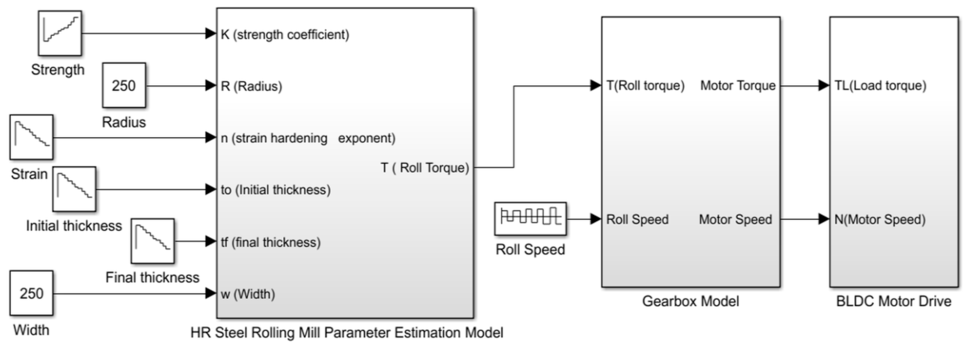
7. Simulation Schematic
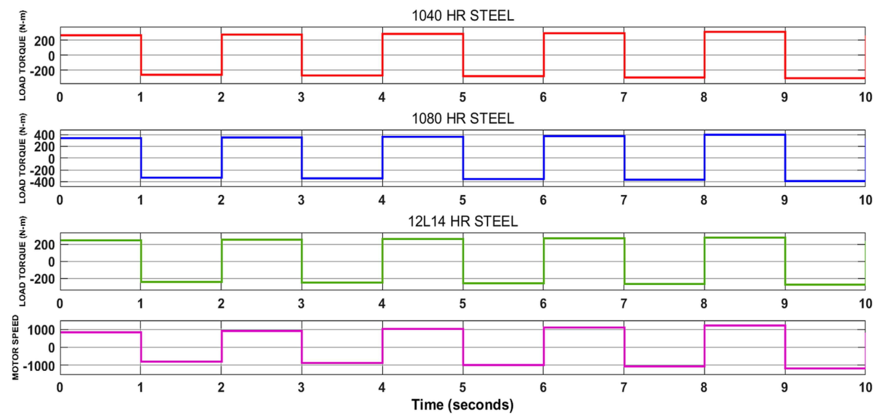
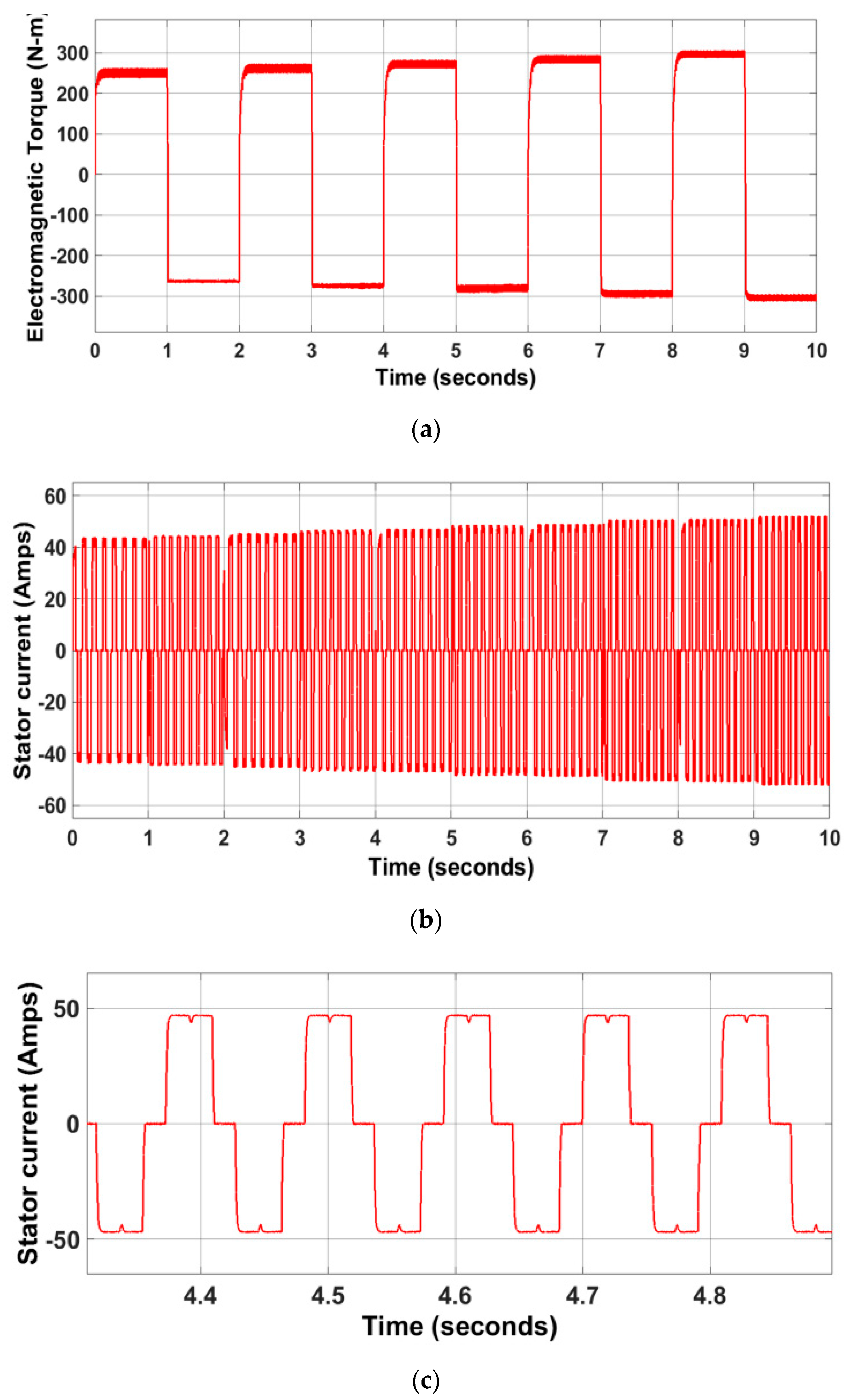
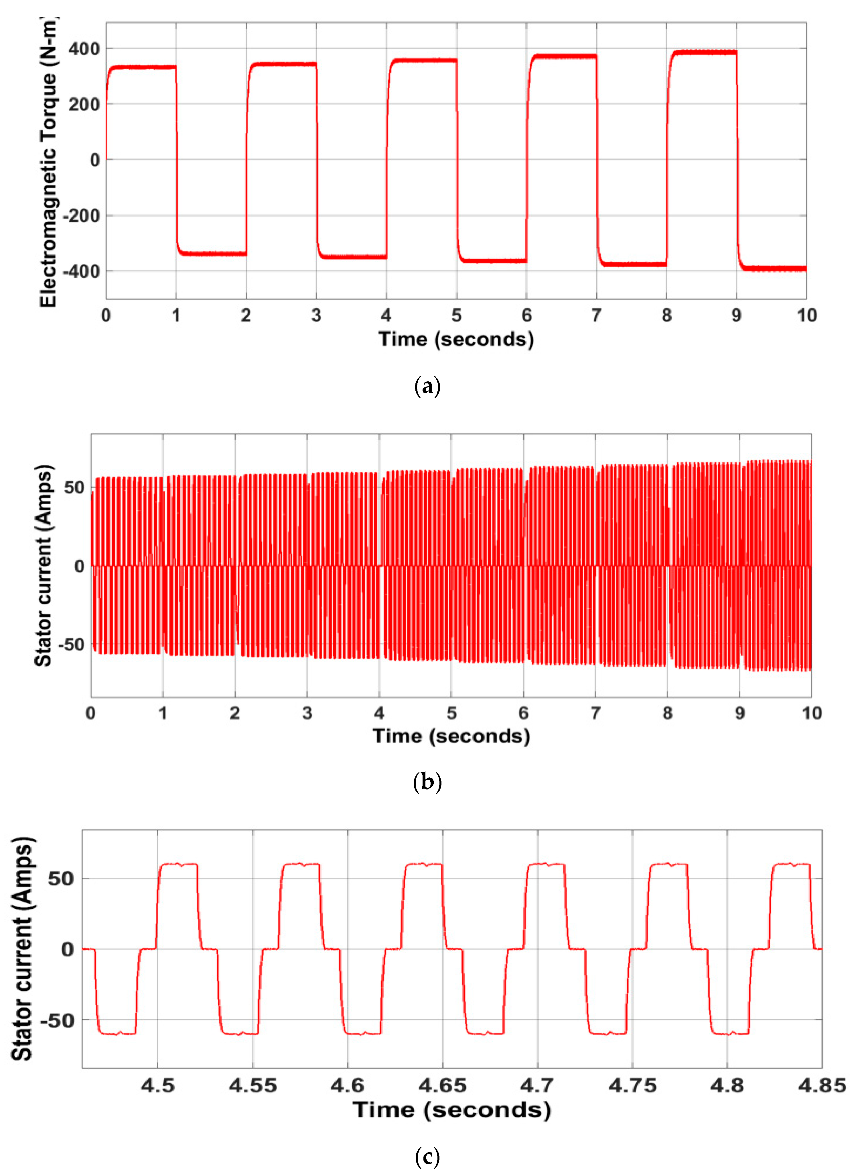
The MATLAB/Simulink software was used for modeling the overall proposed scheme for the operation of a hot-roughing steel-rolling mill integrated with BLDC motor along with gear box arrangement (Figure 7). Further, in Section 2.1 the hot-roughing steel-rolling process as modeled by Equations (1)–(6) was implemented using Simulink functional blocks and is shown in Figure 8. This schematic required a fairly large set of primary data like work roll radius, width, initial and final thickness of specimen and properties of 3 types of HR steel material and calculated the roll force and roll torque. Simulations run over 10 successive time slots of 1 s each generated the roll torque and speed profiles covering a total duration of 10 s. This profile represents the operating conditions of the multi-cyclic, forward-reverse rolling process. Figure 7 shows the overall schematic of the BLDC motor based drive system incorporating power circuit and control modules, so as to implement speed and current feedback algorithm [25,26,27,28,29]. The mechanical-load demand on the motor shaft in terms of shaft speed and torque were deduced from the profile of the rolling process by considering parameters of the gear train arrangement. This arrangement consisted of gear box modeled with a gear reduction ratio of 40:1 with gear box efficiency of 0.98. Figure 9 presents the MATLAB/Simulink model in closed-loop operation of BLDC motor.

Simulation Results

Figure 10 shows the simulation results of the profiles corresponding to the speed and shaft torque values calculated for 3 different HR steel specimens viz. 1040 HR, 1080 HR, 12L14 HR. The profile values indicate the geared-down values of roll torque and the corresponding speed of the BLDC motors.
The operation of the entire drive system to meet the speed and torque-profiles was simulated covering a total simulation history of ten seconds. The forward-reverse operation indicated in the profiles requires running of the motor in Quadrant I and Quadrant III alternatively in successive passes. The results show the variation of back-EMF, rotor speed, stator current and electromagnetic torque.
The expanded view of the simulation results of two passes for forward-reverse rolling is shown in Figure 11 depicting 2-quadrant operation of the BLDC drive system. It was seen that the rapid reversal of speed and torque as required in the rolling operation was achieved by the action of the fuzzy logic-based controller in changing the phase sequence of the inverter output. An expanded view of the transition from clockwise to the counter-clockwise rotation of the motor shaft along with the corresponding back-EMF transition is shown in Figure 11. As can be seen in the graph, the response of the drive system for bidirectional steel-rolling was fast. Figure 12 depicts the overall performance of the drive system covering five forward-reverse cycles totaling ten passed of rolling over the duration of 10 s. As can be seen in the graph, the response of the drive system for bidirectional steel rolling was fast.
The stator back-EMF waveform spanning ten seconds is shown in Figure 13; for each motor speed, the corresponding change in the back-EMF waveform can also be observed. The expanded view of back-EMF is shown in Figure 14 to indicate that the back-EMF of the BLDC motor was trapezoidal.
Figure 15, Figure 16 and Figure 17 presents the overall performance of the drive system spanning 5 forward-reverse cycles totaling 10 passes of rolling over a duration of 10 s for 3 different HR steels viz. 1040 HR, 1080 HR and 12L14 HR steels. This clearly indicates a series of stepping up of all variables over successive cycles, as the rolling process progresses indicating the 2-quadrant operation of the BLDC drive system. It is seen that the rapid reversal of speed and torque as required in the rolling operation was achieved by the action of the fuzzy logic-based controller in changing the phase sequence of the inverter output. The applied-load torque alternated every second and was bidirectional in shape, which was termed as the reference torque. The developed electromagnetic torque followed the reference torque continuously. Figure 15, Figure 16 and Figure 17 displays the variation and expanded views of transition of shaft torque and stator current in Phase A. Table 5 shows the ratings and parameters of the BLDC motor used in this study.
Several controllers were employed for checking the performance of the developed system. Its ability to track the reference speed could be observed from the expanded view (Figure 18a,b). The uniqueness of the fuzzy-logic controller performance was superior in terms of steady-state tracking, lesser overshoot and undershoots rather than the other two controllers employed. The overall system provided better performance in achieving the profile values rather than motor drive system using neural network compensation.

8. Experimental Setup

The block diagram consisted of a BLDC motor with loading arrangements, an IGBT-based intelligent power module (IPM) and arm processor development board—along with speed sensors and interfaces required for the closed-loop operation of the drive system (Figure 19). Here, three-phase power from the AC mains was supplied to the diode bridge rectifier, which was converted into DC supply and fed to the 3-phase inverter supplying power to the BLDC motor. The actual speed of the motor was sensed and compared with the set or reference speed and accordingly; a control algorithm was employed for the generation of reference torque. The reference torque responsible for the production of three-phase reference current was compared with actual motor current and hysteresis control algorithm was employed for the calculation of gate signals to trigger the controlled switches of the three-phase inverter at various timing instants. The computation performed from sensing to the gate signal production at various instants, the control algorithm was developed and embedded into the arm microcontroller. Based on this action, the arm microcontroller provided the triggering signals at different instants which were interfaced through gate drivers to the controlled devices essential for running the BLDC motor. The BLDC motor drive set up was interfaced with CPU for monitoring the actual and reference speed and displayed the speed waveforms through a graphical user interface (GUI). This facility allowed monitoring of the actual speed of the BLDC motor and reference speed in the Simulink scope window. The experimental set up of the entire drive system is shown in Figure 20.
The online monitoring of the actual motor speed based on the set speed adjustment displayed in GUI was captured and shown in Figure 21. The set or reference speed indicated in red color spans over a range of 800 RPM to 1300 RPM in steps of 100 RPM. The actual motor speed indicated in blue color follows the set speed, even though we changed the speed value at various instants of time. The control algorithm embedded in the arm microcontroller was much efficient to adopt changes in following the set speed.

9. Conclusions

The work described in this study commences with the mathematical modeling of hot rough-steel-rolling mill taking into account the metallurgical and mechanical aspects of the process for three different specimens of steel. A pair of profiles for the variation of roll speed and roll torque covering multipass forward–reverse rolling was generated in MATLAB/Simulink using the above model. The overall Simulink schematic also included the BLDC motor model and fuzzy logic-based controller model. The profile calculations obtained from steel rolling process were utilized as command inputs by the controller, which was configured with an outer speed and an inner current feedback loop. Performance of the whole system was evaluated by simulating the overall schematic and the resulted covering a set of electrical and mechanical variables are presented. The results confirm that the range of speed and torque as required over successive forward–reverse passes in the rolling operation were successfully met by the drive system. The results indicate satisfying rapid reversal of rolling speed and the corresponding roll torque over successive passes suggested an energy-efficient solution. It could be well witnessed that the fuzzy-based controller for BLDC motor could definitely play a vital game changing role as an alternate solution to induction motor drive for steel rolling.
It could be clearly concluded from the validation of hardware and simulation results that the novel application of a BLDC motor with a fuzzy logic-based controller was a highly effective approach. The efficacy of novel contribution proposed in this study for the first time could be witnessed from the validation of the resulted pertaining to BLDC motor with its fuzzy-based controller thereby serving to be an attractive alternative to conventional induction motor-drive systems for steel rolling applications. It could be well witnessed that the proposed fuzzy-based controller responds rapidly within a time period of 0.0001 s, compared to conventional PI and tuned PI that takes more than 0.003 s. The superiority in the performance in terms of faster response gives it a major edge as a part of the proposed application.
In contrast to conventional induction motor drive, the most quantifiable finding of this study is that the novel approach of employing fuzzy-based BLDC motor was far superior in terms of performance and a highly energy-efficient approach. This study will serve as a reference for all researchers and engineers working in this domain to effectively employ this methodology in steel rolling mill applications.

Author Contributions

M.N. performed the work under the guidance and direction of S.R., S.N. and S.S.R. All authors analyzed the data and contributed towards the paper. M.N. wrote the paper and executed the experiments under the guidance, supervision and suggestions from S.R., S.N. and S.S.R. All authors have read and agreed to the published version of the manuscript.

Funding

This research received no external funding.

Acknowledgments

Authors would like to thank the management of SASTRA Deemed University and the R& D lab at Power electronics and drives laboratory of SEEE at SASTRA University for providing necessary facilities to carry out the research.

Conflicts of Interest

The authors declare no conflict of interest.

References

  1. Lee, D.; Moon, C.; Moon, S.C.; Park, H. Development of healing control technology for reducing breakout in thin slab casters. Control Eng. Pract. 2009, 17, 3–13. [Google Scholar] [CrossRef]
  2. Yamada, F.; Sekiguchi, K.; Tsugeno, M.; Anbe, Y.; Andoh, Y.; Forse, C.; Guernier, M.; Coleman, T. Hot Strip Mill Mathematical models and Set Up Calculation. Ind. Appl. 1991, 27, 131–139. [Google Scholar] [CrossRef]
  3. Bose, B. Power Electronics and Motor Drives Recent Progress and Perspective. IEEE Trans. Ind. Electron. 2008, 56, 581–588. [Google Scholar] [CrossRef]
  4. Xu, F.P.; Li, T.C.; Tang, P.H. A low cost drive strategy for BLDC motor with low torque ripples. In Proceedings of the IEEE Conference on Industrial Electronics and Applications, Singapore, 3–5 June 2008. [Google Scholar]
  5. Lianbing, L.; Hui, J.; LiQiang, Z.; Hexu, S. Study on Torque Ripple Attenuation for BLDCM Based on Vector Control Method. In Proceedings of the 2009 Second International Conference on Intelligent Networks and Intelligent Systems, Tianjin, China, 1–3 November 2009. [Google Scholar]
  6. Matlab, Version 7.1. 2005. Available online: http://www.mathworks.com (accessed on 1 February 2012).
  7. Potnuru, D.; Ch, S. Design and implementation methodology for rapid control prototyping of closed loop speed control for BLDC motor. J. Electr. Syst. Inf. Technol. 2018, 5, 99–111. [Google Scholar] [CrossRef]
  8. El-Samahy, A.A.; Shamseldin, M.A. Brushless DC motor tracking control using self-tuning fuzzy PID control and model reference adaptive control. Ain Shams Eng. J. 2018, 9, 341–352. [Google Scholar] [CrossRef] [Green Version]
  9. Ravell, D.A.M.; Maia, M.M.; Diez, F.J. Modeling and control of unmanned aerial/underwater vehicles using hybrid control. Control Eng. Pract. 2018, 76, 112–122. [Google Scholar] [CrossRef]
  10. Pillay, P.; Krishnan, R. Modeling, simulation, and analysis of permanent- magnet motor drives, part II: The brushless dc motor drive. IEEE Trans. Ind. Appl 1989, IA-25, 274–279. [Google Scholar] [CrossRef]
  11. Kim, I.; Nakazawa, N.; Kim, S.; Park, C.; Yu, C. Compensation of torque ripple in high performance BLDC motor drives. Control Eng. Pract. 2010, 18, 1166–1172. [Google Scholar] [CrossRef] [Green Version]
  12. Mahfouf, M.; Yang, Y.Y.; Gama, M.A.; Linkens, D.A. Roll Speed and Roll Gap Control with Neural Network Compensation. ISIJ Int. 2005, 45, 841–850. [Google Scholar] [CrossRef] [Green Version]
  13. Niapour, S.M.; Tabarraie, M.; Feyzi, M. A new robust speed-sensorless control strategy for high-performance brushless DC motor drives with reduced torque ripple. Control Eng. Pract. 2014, 24, 42–54. [Google Scholar] [CrossRef]
  14. Mazaheri, A.; Radan, A. Performance evaluation of nonlinear Kalman filtering techniques in low speed brushless DC motors driven sensor-less positioning systems. Control Eng. Pract. 2017, 60, 148–156. [Google Scholar] [CrossRef]
  15. Lu, H.; Zhang, L.; Qu, W. A New Torque Control Method for Torque Ripple Minimization of BLDC Motors With Un-Ideal Back EMF. IEEE Trans. Power Electron. 2008, 23, 950–958. [Google Scholar] [CrossRef]
  16. Shi, T.; Guo, Y.; Song, P.; Xia, C. A New Approach of Minimizing Commutation Torque Ripple for Brushless DC Motor Based on DC–DC Converter. IEEE Trans. Ind. Electron. 2009, 57, 3483–3490. [Google Scholar] [CrossRef]
  17. Salah, W.A.; Ishak, D.; Hammadi, K. PWM Switching Strategy for Torque Ripple Minimization in BLDC Motor. J. Electr. Eng. 2011, 62, 141–146. [Google Scholar] [CrossRef] [Green Version]
  18. Sathyan, A.; Milivojevic, N.; Lee, Y.J.; Krishnamurthy, M.; Emadi, A. An FPGA-Based Novel Digital PWM Control Scheme for BLDC Motor Drives. IEEE Trans. Ind. Electron. 2009, 56, 3040–3049. [Google Scholar] [CrossRef]
  19. Zhao, J.; Wang, W.; Liu, Q.; Wang, Z.; Shi, P. A two-stage scheduling method for hot rolling and its application. Control Eng. Pract. 2009, 17, 629–641. [Google Scholar] [CrossRef]
  20. Ma, L.; Dong, J.; Peng, K.; Zhang, K. A novel data-based quality-related fault diagnosis scheme for fault detection and root cause diagnosis with application to hot strip mill process. Control Eng. Pract. 2017, 67, 43–51. [Google Scholar] [CrossRef]
  21. Steinboeck, A.; Wild, D.; Kugi, A. Nonlinear model predictive control of a continuous slab reheating furnace. Control Eng. Pract. 2013, 21, 495–508. [Google Scholar] [CrossRef]
  22. Lotter, U.; Schmitz, H.P.; Zhang, L. Application of the Metallurgically Oriented Simulation System “TKS-StripCam” to Predict the Properties of Hot Strip Steels from the Rolling Conditions. Adv. Eng. Mater. 2002, 4, 207–213. [Google Scholar] [CrossRef]
  23. Ko, J.S. Robust position control of BLDC motors using Integral-Proportional-Plus Fuzzy logic controller. IEEE Trans. IE 1994, 41, 308–315. [Google Scholar]
  24. Li, W. Design of a hybrid fuzzy logic proportional plus conventional integral-derivative controller. IEEE Trans. Fuzzy Syst. 1998, 6, 449–463. [Google Scholar] [CrossRef] [Green Version]
  25. ASM Metals Handbook, Forming and Forging. ASM Int. 1996, 14, 351–355.
  26. Mikell, P. Groover Fundamentals of Modern Manufacturing. In Materials, Processes and Systems, 4th ed.; John Wiley & Sons: Hoboken, NJ, USA, 2010; pp. 395–403. [Google Scholar]
  27. AISI/SAE Standard (American Iron and Steel Institute/Society of Automotive Engineers). SAE 2014, J403, 1010.
  28. AISI/SAE Standard (American Iron and Steel Institute/Society of Automotive Engineers). SAE 2014, J403.
  29. Varshney, A.; Gupta, D.; Dwivedi, B. Speed response of brushless DC motor using fuzzy PID controller under varying load condition. J. Electr. Syst. Inf. Technol. 2017, 4, 310–321. [Google Scholar] [CrossRef]
Figure 1. Schematic of two identical brushless electric DC (BLDC) motor drive systems coupled to steel rolling mill through reduction gears.
Electronics 09 01008 g001
Figure 2. Schematic of steel rolling mill model and BLDC motor drive system.
Electronics 09 01008 g002
Figure 3. 1040 HR steel characteristics (a) K at different temperatures; (b) n at different temperatures.
Electronics 09 01008 g003
Figure 4. 1080 HR steel characteristics (a) K at different temperatures; (b) n at different temperatures.
Electronics 09 01008 g004
Figure 5. 12L14 HR steel characteristics (a) K at different temperatures; (b) n at different temperatures.
Electronics 09 01008 g005
Figure 6. Fuzzy logic controller in MATLAB/Simulink.
Electronics 09 01008 g006
Figure 7. MATLAB/Simulink model of BLDC motor-drive system coupled with rolling process.
Electronics 09 01008 g007
Figure 8. MATLAB/Simulink model of steel rolling process.
Electronics 09 01008 g008
Figure 9. MATLAB/Simulink model in closed-loop operation of BLDC motor.
Electronics 09 01008 g009
Figure 10. Speed and load torque demand at the work roll for 3 different HR steel.
Electronics 09 01008 g010
Figure 11. Expanded view of first two passes for forward-reverse rolling.
Electronics 09 01008 g011
Figure 12. Actual speed of the BLDC motor for ten seconds.
Electronics 09 01008 g012
Figure 13. Stator back-EMF of BLDC motor for ten seconds.
Electronics 09 01008 g013
Figure 14. Expanded view of the stator back-EMF of the BLDC motor.
Electronics 09 01008 g014
Figure 15. (a) Electromagnetic torque developed by a motor using the parameters of 1040 HR steel; (b) stator current in Phase A of a motor using the parameters of 1040 HR steel; (c) expanded stator current waveform in Phase A of motor corresponding to 1040 HR steel.
Electronics 09 01008 g015
Figure 16. (a) Electromagnetic torque developed by a motor using the parameters of 1040 HR; (b) stator current in Phase A of a motor using the parameters of 1080 HR steel; (c) expanded stator current waveform in Phase A of motor corresponding to 1080 HR steel.
Electronics 09 01008 g016
Figure 17. (a) Electromagnetic torque developed by a motor using the parameters of 12L14 HR steel; (b) stator current in Phase A of a motor using the parameters of 12L14 HR steel; (c) expanded waveform of stator current in Phase A of motor corresponding to 12L14 HR steel.
Electronics 09 01008 g017
Figure 18. (a) Comparison of speeds for various controllers; (b) expanded view for various controllers.
Electronics 09 01008 g018
Figure 19. Block diagram of real-time BLDC motor drive system.
Electronics 09 01008 g019
Figure 20. Experimental set up of BLDC motor drive system.
Electronics 09 01008 g020
Figure 21. Online monitoring of set speed and the actual speed of motor through a graphical user interface (GUI).
Electronics 09 01008 g021
Table 1. Properties of three different hot-rolled (HR) steel materials.
Properties1040
HR Steel
1080
HR Steel
12L14
HR Steel
Tensile strength (MPa)620772540
Yield strength (MPa)415425415
Elastic modulus (GPa)190–210205190–210
Poisson ratio0.27–0.300.290.27–0.30
Vickers hardness211241170
Density (gr/cm3)7.8457.7–8.037.87
Table 2. Rolling parameters at 10 passes for 3 different HR steel materials.
PassTemperature °C1040 HR1080 HR12L14 HR
K, MPanK, MPanK, MPan
18153450.253600.212300.18
28103460.2583640.21022310.179
38053480.2563690.21042320.1792
48003490.2553720.21062330.1788
57953500.2533760.21082340.1784
67903510.2523800.21102350.1780
77853520.2503840.21122360.1776
87803540.2483880.21142370.1772
97753550.2473920.21162380.1768
107703580.2463960.21182390.1764
Table 3. Speed and torque-profile values for 10 passes of 3 different HR steel materials.
Time
Duration
(s)
Reduced Thickness
(cm)
Roller
Speed
(RPM)
Motor
Speed
(RPM)
Load Torque for 3 Different HR Steel Materials
1040 HR
(N-m)
1080 HR
(N-m)
12l14 HR
(N-m)
19.720800258.89334.97243.68
19.4−20−800−263.98−340.60−246.53
19.122.5900269.97346.37249.45
18.8−22.5−900−274.19−352.28−252.43
18.5251000279.69358.33255.50
18.2−25−1000−284.18−364.55−258.64
17.927.51100289.99370.93261.87
17.6−27.5−1100−296.81−377.51−265.20
17.3301200301.79384.29268.62
17.0−30−1200−309.16−391.29−272.16
Table 4. Rule Table for fuzzy logic controller.
ΔeNBNMNSZPSPMPB
e
NBNBNBNBNMNSNSZ
NMNBNMNMNMNSZPS
NSNBNMNSNSZPSPM
ZNBNMNSZPSPMPB
PSNMNSZPSPSPMPB
PMNSZPSPMPMPMPB
PBZPSPSPMPMPBPB
Table 5. BLDC motor parameters.
Motor Mating62 HP
Voltage500 V
Rated speed1500 RPM
Phase resistance0.2 Ω
Phase inductance
Number of pole pairs
Back EMF
8.5 mH
2
Trapezoidal

